Gigabyte GA-8I945GMF-RH: Chapter 2 BIOS Setup
Chapter 2 BIOS Setup: Gigabyte GA-8I945GMF-RH

English
Chapter 2 BIOS Setup
BIOS (Basic Input and Output System) includes a CMOS SETUP utility which allows user to configure
required settings or to activate certain system features.
The CMOS SETUP saves the configuration in the CMOS SRAM of the motherboard.
When the power is turned off, the battery on the motherboard supplies the necessary power to the CMOS
SRAM.
When the power is turned on, pushing the <Del> button during the BIOS POST (Power-On Self Test) will
take you to the CMOS SETUP screen. You can enter the BIOS setup screen by pressing "Ctrl + F1".
When setting up BIOS for the first time, it is recommended that you save the current BIOS to a disk in the
event that BIOS needs to be reset to its original settings. If you wish to upgrade to a new BIOS, either
Gigabyte's Q-Flash or @BIOS utility can be used.
Q-Flash allows the user to quickly and easily update or backup BIOS without entering the operating system.
@BIOS is a Windows-based utility that does not require users to boot to DOS before upgrading BIOS but
directly download and update BIOS from the Internet.
CONTROL KEYS
< >< >< >< > Move to select item
<Enter> Select Item
<Esc> Main Menu - Quit and not save changes into CMOS Status Page Setup Menu
and Option Page Setup Menu - Exit current page and return to Main Menu
<Page Up> Increase the numeric value or make changes
<Page Down> Decrease the numeric value or make changes
<F1> General help, only for Status Page Setup Menu and Option Page Setup Menu
<F2> Item Help
<F5> Restore the previous CMOS value from CMOS, only for Option Page Setup Menu
<F6> Load the file-safe default CMOS value from BIOS default table
<F7> Load the Optimized Defaults
<F8> Q-Flash utility
<F9> System Information
<F10> Save all the CMOS changes, only for Main Menu
Main Menu
The on-line description of the highlighted setup function is displayed at the bottom of the screen.
Status Page Setup Menu / Option Page Setup Menu
Press F1 to pop up a small help window that describes the appropriate keys to use and the possible selec-
tions for the highlighted item. To exit the Help Window press <Esc>.
BIOS Setup- 29 -

The Main Menu (For example: BIOS Ver. : F2)
Once you enter Award BIOS CMOS Setup Utility, the Main Menu (as figure below) will appear on the
screen. Use arrow keys to select among the items and press <Enter> to accept or enter the sub-menu.
English
CMOS Setup Utility-Copyright (C) 1984-2005 Award Software
` Standard CMOS Features
Load Fail-Safe Defaults
` Advanced BIOS Features
Load Optimized Defaults
` Integrated Peripherals
Set Supervisor Password
` Power Management Setup
Set User Password
` PnP/PCI Configurations
Save & Exit Setup
` PC Health Status
Exit Without Saving
` Frequency/Voltage Control
ESC: Quit KLJI: Select Item
F8: Q-Flash F10: Save & Exit Setup
Time, Date, Hard Disk Type...
If you can't find the setting you want, please press "Ctrl+F1" to search the advanced option
hidden.
Please Load Optimized Defaults in the BIOS when somehow the system works not stable as
usual. This action makes the system reset to the default for stability.
Standard CMOS Features
This setup page includes all the items in standard compatible BIOS.
Advanced BIOS Features
This setup page includes all the items of Award special enhanced features.
Integrated Peripherals
This setup page includes all onboard peripherals.
Power Management Setup
This setup page includes all the items of Green function features.
PnP/PCI Configuration
This setup page includes all the configurations of PCI & PnP ISA resources.
PC Health Status
This setup page is the System auto detect Temperature, voltage, fan, speed.
Frequency / Voltage Control
This setup page is control CPU clock and frequency ratio.
Load Fail-Safe Defaults
Fail-Safe Defaults indicates the value of the system parameters which the system would be in safe
configuration.
Load Optimized Defaults
Optimized Defaults indicates the value of the system parameters which the system would be in best
performance configuration.
Set Supervisor Password
Change, set, or disable password. It allows you to limit access to the system and Setup, or just to Setup.
GA-8I945GMF-RH Motherboard - 30 -

Set User Password
English
Change, set, or disable password. It allows you to limit access to the system.
Save & Exit Setup
Save CMOS value settings to CMOS and exit setup.
Exit Without Saving
Abandon all CMOS value changes and exit setup.
BIOS Setup- 31 -
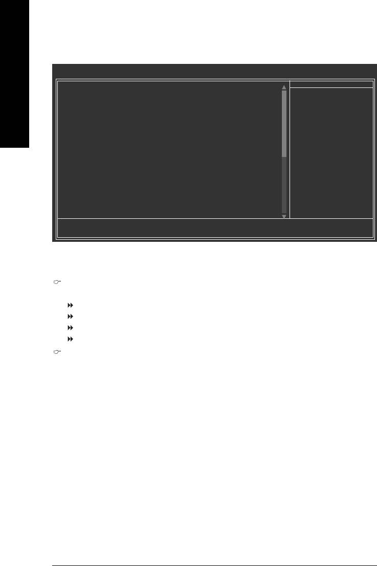
2-1 Standard CMOS Features
CMOS Setup Utility-Copyright (C) 1984-2005 Award Software
Standard CMOS Features
Date (mm:dd:yy) Mon, Mar 28 2005
Item Help
English
Time (hh:mm:ss) 22:31:24
Menu Level`
` IDE Channel 0 Master [None]
Change the day, month,
` IDE Channel 0 Slave [None]
year
<Week>
Drive A [1.44M, 3.5"]
Sun. to Sat.
Drive B [None]
Floppy 3 Mode Suport [Disabled]
<Month>
Jan. to Dec.
Holt On [All, But Keyboard]
<Day>
Base Memory 640K
1 to 31 (or maximum
Extended Memory 127M
allowed in the month)
Total Memory 128M
<Year>
1999 to 2098
KLJI: Move Enter: Select +/-/PU/PD: Value F10: Save ESC: Exit F1: General Help
F5: Previous Values F6: Fail-Save Default F7: Optimized Defaults
Date
The date format is <week>, <month>, <day>, <year>.
Week The week, from Sun to Sat, determined by the BIOS and is display only
Month The month, Jan. Through Dec.
Day The day, from 1 to 31 (or the maximum allowed in the month)
Year The year, from 1999 through 2098
Time
The times format in <hour> <minute> <second>. The time is calculated base on the 24-hour
military-time clock. For example, 1 p.m. is 13:00:00.
GA-8I945GMF-RH Motherboard - 32 -

English
IDE Channel 0 Master, Slave
IDE HDD Auto-Detection Press "Enter" to select this option for automatic device detection.
IDE Channel 0 Master(Slave) IDE Device Setup. You can use one of three methods:
Auto Allows BIOS to automatically detect IDE devices during POST(default)
None Select this if no IDE devices are used and the system will skip the automatic
detection step and allow for faster system start up.
Manual User can manually input the correct settings
Access Mode Use this to set the access mode for the hard drive. The four options are:
CHS/LBA/Large/Auto(default:Auto)
Hard drive information should be labeled on the outside drive casing. Enter the appropriate option
based on this information.
Cylinder Number of cylinders
Head Number of heads
Precomp Write precomp
Landing Zone Landing zone
Sector Number of sectors
If a hard disk has not been installed, select NONE and press <Enter>.
Drive A / Drive B
The category identifies the types of floppy disk drive A or drive B that has been installed in the computer.
None No floppy drive installed
360K, 5.25" 5.25 inch PC-type standard drive; 360K byte capacity.
1.2M, 5.25" 5.25 inch AT-type high-density drive; 1.2M byte capacity
(3.5 inch when 3 Mode is Enabled).
720K, 3.5" 3.5 inch double-sided drive; 720K byte capacity
1.44M, 3.5" 3.5 inch double-sided drive; 1.44M byte capacity.
2.88M, 3.5" 3.5 inch double-sided drive; 2.88M byte capacity.
Floppy 3 Mode Support (for Japan Area)
Disabled Normal Floppy Drive. (Default value)
Drive A Drive A is 3 mode Floppy Drive.
Drive B Drive B is 3 mode Floppy Drive.
Both Drive A & B are 3 mode Floppy Drives.
Halt on
The category determines whether the computer will stop if an error is detected during power up.
No Errors The system boot will not stop for any error that may be detected and you
will be prompted.
All Errors Whenever the BIOS detects a non-fatal error the system will be stopped.
All, But Keyboard The system boot will not stop for a keyboard error; it will stop for all other
errors. (Default value)
All, But Diskette The system boot will not stop for a disk error; it will stop for all other errors.
All, But Disk/Key The system boot will not stop for a keyboard or disk error; it will stop for all
other errors.
BIOS Setup- 33 -

Memory
The category is display-only which is determined by POST (Power On Self Test) of the BIOS.
Base Memory
English
The POST of the BIOS will determine the amount of base (or conventional) memory installed
in the system.
The value of the base memory is typically 512K for systems with 512K memory installed on
the motherboard, or 640K for systems with 640K or more memory installed on the motherboard.
Extended Memory
The BIOS determines how much extended memory is present during the POST.
This is the amount of memory located above 1 MB in the CPU's memory address map.
GA-8I945GMF-RH Motherboard - 34 -
English
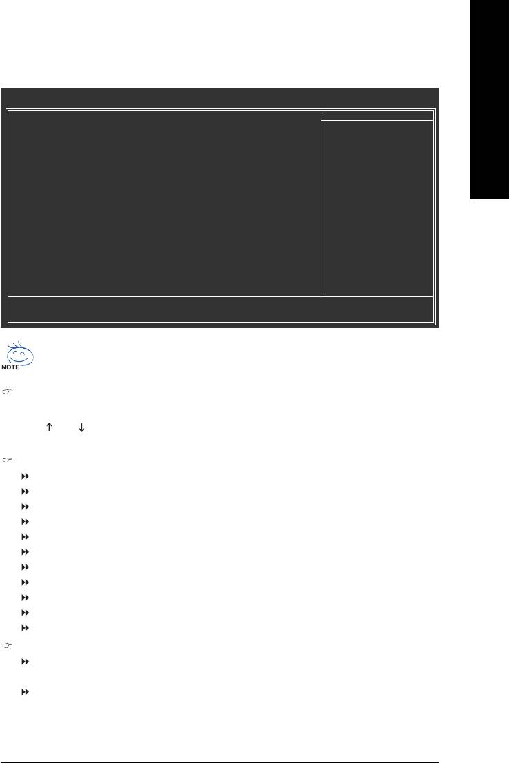
2-2 Advanced BIOS Features
CMOS Setup Utility-Copyright (C) 1984-2005 Award Software
Advanced BIOS Features
` Hard Disk Boot Priority [Press Enter]
Item Help
First Boot Device [Floppy]
Menu Level`
Second Boot Device [Hard Disk]
Third Boot Device [CDROM]
Select Hard Disk Boot
Password Check [Setup]
Device Priority
# CPU Hyper-Threading [Enabled]
Limit CPUID Max. to 3 [Disabled]
(Note)
No-Execute Memory Protect
[Enabled]
(Note)
CPU Enhanced Halt (C1E)
[Enabled]
(Note)
CPU Thermal Monitor 2(TM2)
[Enabled]
(Note)
CPU EIST Function
[Enabled]
On-Chip Frame Buffer Size [8MB]
KLJI: Move Enter: Select +/-/PU/PD: Value F10: Save ESC: Exit F1: General Help
F5: Previous Values F6: Fail-Save Default F7: Optimized Defaults
®
®
" # " System will detect automatically and show up when you install the Intel
Pentium
4
processor with HT Technology.
Hard Disk Boot Priority
Select boot sequence for onboard(or add-on cards) SCSI, RAID, etc.
Use < > or < > to select a device, then press<+> to move it up, or <-> to move it down the list. Press
<ESC> to exit this menu.
First / Second / Third Boot Device
Floppy Select your boot device priority by Floppy.
LS120 Select your boot device priority by LS120.
Hard Disk Select your boot device priority by Hard Disk.
CDROM Select your boot device priority by CDROM.
ZIP Select your boot device priority by ZIP.
USB-FDD Select your boot device priority by USB-FDD.
USB-ZIP Select your boot device priority by USB-ZIP.
USB-CDROM Select your boot device priority by USB-CDROM.
USB-HDD Select your boot device priority by USB-HDD.
LAN Select your boot device priority by LAN.
Disabled Disabled this function.
Password Check
Setup The system will boot but will not access to Setup page if the correct
password is not entered at the prompt. (Default value)
System The system will not boot and will not access to Setup page if the correct
password is not entered at the prompt.
(Note) This item will show up when you install a processor which supports this function.
BIOS Setup- 35 -

CPU Hyper-Threading
Enabled Enables CPU Hyper Threading Feature. Please note that this feature is only working
for operating system with multi processors mode supported. (Default value)
Disabled Disables CPU Hyper Threading.
English
Limit CPUID Max. to 3
Enabled Limit CPUID Maximum value to 3 when use older OS like NT4.
Disabled Disables CPUID Limit for windows XP.(Default value)
(Note)
No-Execute Memory Protect
Enabled Enables No-Execute Memory Protect function. (Default value)
Disabled Disables No-Execute Memory Protect function.
(Note)
CPU Enhanced Halt (C1E)
Enabled Enables CPU Enhanced Halt (C1E) function. (Default value)
Disabled Disables CPU Enhanced Halt (C1E) function.
(Note)
CPU Thermal Monitor 2 (TM2)
Enabled Enable CPU Thermal Monitor 2 (TM2) function. (Default value)
Disabled Disable CPU Thermal Monitor 2 (TM2) function.
(Note)
CPU EIST Function
Enabled Enable CPU EIST function. (Default value)
Disabled Disable EIST function.
On-Chip Frame Buffer Size
1MB Set On-chip frame buffer size to 1MB.
8MB Set On-chip frame buffer size to 8MB. (Default value)
(Note) This item will show up when you install a processor which supports this function.
GA-8I945GMF-RH Motherboard - 36 -

English
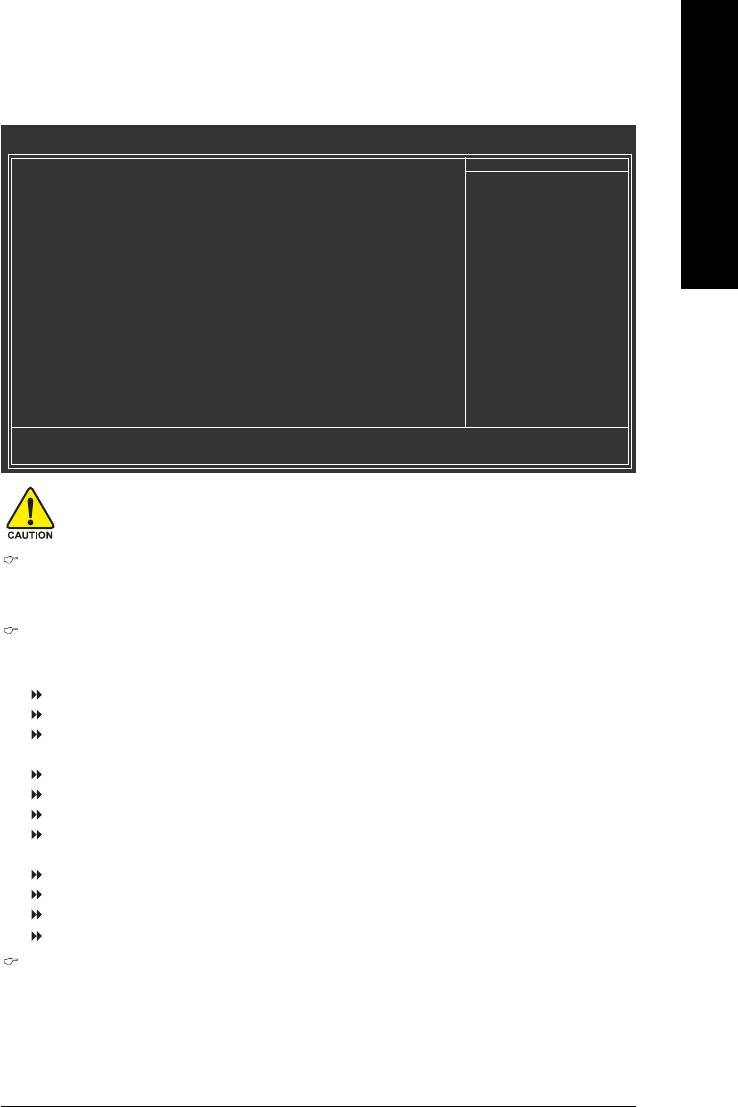
2-3 Integrated Peripherals
CMOS Setup Utility-Copyright (C) 1984-2004 Award Software
Integrated Peripherals
On-Chip Primary PCI IDE [Enabled]
Item Help
On-Chip Secondary PCI IDE [Enabled]
Menu Level`
On-Chip SATA Mode [Auto]
x PATA IDE Set to Ch.0 Master/Slave
SATA Port 0/2 Set to Ch.2 Master/Slave
SATA Port 1/3 Set to Ch.3 Master/Slave
USB Controller [Enabled]
USB 2.0 Controller [Enabled]
USB Keyboard Support [Disabled]
USB Mouse Support [Disabled]
Azalia Codec [Auto]
Onboard H/W 1394 [Enabled]
Onboard H/W LAN [Enabled]
Onboard LAN Boot ROM [Disabled]
Onboard Serial Port 1 [3F8/IRQ4]
G-Keyless Port [Enabled]
Onboard Parallel Port [378/IRQ7]
Parallel Port Mode [SPP]
x ECP Mode Use DMA 3
KLJI: Move Enter: Select +/-/PU/PD: Value F10: Save ESC: Exit F1: General Help
F5: Previous Values F6: Fail-Save Default F7: Optimized Defaults
On-Chip Primary PCI IDE
Enabled Enable onboard 1st channel IDE port. (Default value)
Disabled Disable onboard 1st channel IDE port.
On-Chip Secondary PCI IDE
Enabled Enable onboard 2nd channel IDE port. (Default value)
Disabled Disable onboard 2nd channel IDE port.
On-Chip SATA Mode
Disabled Disable this function.
Auto BIOS will auto detect. (Default value)
Combined Set On-Chip SATA mode to Combined, you can use up to 4 HDDs on
the motherboard; 2 for SATA and the other for PATA IDE.
Enhanced Set On-Chip SATA mode to Enhanced, the motherboard allows up to 6
HDDs to use.
Non-Combined Set On-Chip SATA mode to Non-Combined, SATA will be simulated to
PATA mode.
PATA IDE Set to
Ch.1 Master/Slave Set PATA IDE to Ch. 1 Master/Slave. (Default value)
Ch.0 Master/Slave Set PATA IDE to Ch. 0 Master/Slave.
SATA Port 0/2 Set to
This value will auto make by the setting "On-Chip SATA Mode" and "PATA IDE Set to".
If PATA IDE were set to Ch. 1 Master/Slave, this function will auto set to Ch. 0 Master/Slave.
SATA Port 1/3 Set to
This value will auto make by the setting "On-Chip SATA Mode" and "PATA IDE Set to".
If PATA IDE were set to Ch. 0 Master/Slave, this function will auto set to Ch. 1 Master/Slave.
USB Controller
Enabled Enable USB Controller. (Default value)
Disabled Disable USB Controller.
BIOS Setup- 37 -

USB 2.0 Controller
Disable this function if you are not using onboard USB 2.0 feature.
Enabled Enable USB 2.0 Controller. (Default value)
Disabled Disable USB 2.0 Controller.
English
USB Keyboard Support
Enabled Enable USB Keyboard Support.
Disabled Disable USB Keyboard Support. (Default value)
USB Mouse Support
Enabled Enable USB Mouse Support.
Disabled Disable USB Mouse Support. (Default value)
Azalia Codec
Auto Auto detect Azalia audio function. (Default value)
Disabled Disable Azalia audio function.
Onboard H/W 1394
Enabled Enable onboard IEEE 1394 function.(Default value)
Disabled Disable this function.
Onboard H/W LAN
Enabled Enable Onboard H/W LAN function. (Default value)
Disabled Disable this function.
Onboard LAN Boot ROM
This function decide whether to invoke the boot ROM of the onboard LAN chip.
Enabled Enable this function.
Disabled Disable this function. (Default value)
Onboard Serial Port 1
Auto BIOS will automatically setup the port 1 address.
3F8/IRQ4 Enable onboard Serial port 1 and address is 3F8/IRQ4. (Default value)
2F8/IRQ3 Enable onboard Serial port 1 and address is 2F8/IRQ3.
3E8/IRQ4 Enable onboard Serial port 1 and address is 3E8/IRQ4.
2E8/IRQ3 Enable onboard Serial port 1 and address is 2E8/IRQ3.
Disabled Disable onboard Serial port 1.
G-Keyless Port
Enabled Enable G-Keyless port function. (Default value)
Disabled Disable this function.
Onboard Parallel port
Disabled Disable onboard LPT port.
378/IRQ7 Enable onboard LPT port and address is 378/IRQ7. (Default value)
278/IRQ5 Enable onboard LPT port and address is 278/IRQ5.
3BC/IRQ7 Enable onboard LPT port and address is 3BC/IRQ7.
GA-8I945GMF-RH Motherboard - 38 -

English
Parallel Port Mode
SPP Using Parallel port as Standard Parallel Port. (Default value)
EPP Using Parallel port as Enhanced Parallel Port.
ECP Using Parallel port as Extended Capabilities Port.
ECP+EPP Using Parallel port as ECP & EPP mode.
ECP Mode Use DMA
3 Set ECP Mode Use DMA to 3. (Default value)
1 Set ECP Mode Use DMA to 1.
BIOS Setup- 39 -

2-4 Power Management Setup
CMOS Setup Utility-Copyright (C) 1984-2005 Award Software
Power Management Setup
ACPI Suspend Type [S1(POS)]
Item Help
English
Soft-Off by PWR-BTTN [Instant-off]
Menu Level`
PME Event Wake Up [Enabled]
Power On by Ring [Enabled]
Resume by Alarm [Disabled]
x Date (of Month) Alarm Everyday
x Time (hh:mm:ss) Alarm 0 : 0 : 0
Power On By Mouse [Disabled]
Power On By Keyboard [Disabled]
x KB Power ON Password Enter
AC Back Function [Soft-Off]
KLJI: Move Enter: Select +/-/PU/PD: Value F10: Save ESC: Exit F1: General Help
F5: Previous Values F6: Fail-Save Default F7: Optimized Defaults
ACPI Suspend Type
S1(POS) Set ACPI suspend type to S1/POS(Power On Suspend). (Default value)
S3(STR) Set ACPI suspend type to S3/STR(Suspend To RAM).
Soft-off by PWR-BTTN
Instant-off Press power button then Power off instantly. (Default value)
Delay 4 Sec. Press power button 4 sec. to Power off. Enter suspend if button is pressed
less than 4 sec.
PME Event Wake Up
Disabled Disable this function.
Enabled Enable PME Event Wake up. (Default value)
Power On by Ring
Disabled Disable Power on by Ring function.
Enabled Enable Power on by Ring function. (Default value)
Resume by Alarm
You can set "Resume by Alarm" item to enabled and key in Data/time to power on system.
Disabled Disable this function. (Default value)
Enabled Enable alarm function to POWER ON system.
If RTC Alarm Lead To Power On is Enabled.
Date (of Month) Alarm : Everyday, 1~31
Time (hh: mm: ss) Alarm : (0~23) : (0~59) : (0~59)
Power On By Mouse
Disabled Disable this function. (Default value)
Double Click Double click on PS/2 mouse left button to power on the system.
GA-8I945GMF-RH Motherboard - 40 -

English
Power On By Keyboard
Password Enter from 1 to 5 characters to set the Keyboard Power On Password.
Disabled Disabled this function. (Default value)
Keyboard 98 If your keyboard have "POWER Key" button, you can press the key to
power on the system.
KB Power ON Password
When "Power On by Keyboard" set at Password, you can set the password here.
Enter Input password (from 1 to 5 characters) and press Enter to set the Keyboard
Power On password.
AC Back Function
Soft-Off When AC-power back to the system, the system will be in "Off" state.
(Default value)
Full-On When AC-power back to the system, the system always in "On" state.
Memory When AC-power back to the system, the system will return to the Last state
before AC-power off.
BIOS Setup- 41 -

2-5 PnP/PCI Configurations
CMOS Setup Utility-Copyright (C) 1984-2005 Award Software
PnP/PCI Configurations
English
PCI 1 IRQ Assignment [Auto]
Item Help
PCI 2 IRQ Assignment [Auto]
Menu Level`
KLJI: Move Enter: Select +/-/PU/PD: Value F10: Save ESC: Exit F1: General Help
F5: Previous Values F6: Fail-Save Default F7: Optimized Defaults
PCI 1 IRQ Assignment
Auto Auto assign IRQ to PCI 1. (Default value)
3,4,5,7,9,10,11,12,14,15 Set IRQ 3,4,5,7,9,10,11,12,14,15 to PCI 1.
PCI 2 IRQ Assignment
Auto Auto assign IRQ to PCI 2. (Default value)
3,4,5,7,9,10,11,12,14,15 Set IRQ 3,4,5,7,9,10,11,12,14,15 to PCI 2.
GA-8I945GMF-RH Motherboard - 42 -

English
2-6 PC Health Status
CMOS Setup Utility-Copyright (C) 1984-2005 Award Software
PC Health Status
Reset Case Open Status [Disabled]
Item Help
Case Opened Yes
Menu Level`
Vcore OK
DDRV OK
+3.3V OK
+12V OK
o
Current System Temperature 30
C
o
Current CPU Temperature 38
C
Current CPU FAN Speed 4687 RPM
Current SYSTEM FAN Speed 0 RPM
System Warning Temperature [Disabled]
CPU Warning Temperature [Disabled]
CPU FAN Fail Warning [Disabled]
SYSTEM FAN Fail Warning [Disabled]
CPU Smart FAN Control [Enabled]
CPU Smart FAN Mode [Auto]
System Smart FAN Control [Enabled]
KLJI: Move Enter: Select +/-/PU/PD: Value F10: Save ESC: Exit F1: General Help
F5: Previous Values F6: Fail-Save Default F7: Optimized Defaults
Reset Case Open Status
Disabled Don't reset case open status. (Default value)
Enabled Clear case open status at next boot.
Case Opened
If the case is closed, "Case Opened" will show "No".
If the case have been opened, "Case Opened" will show "Yes".
If you want to reset "Case Opened" value, set "Reset Case Open Status" to "Enabled" and save
CMOS, your computer will restart.
Current Voltage(V) Vcore / DDRV / +3.3V / +12V
Detect system's voltage status automatically.
Current System/CPU Temperature
Detect System/CPU temperature automatically.
Current CPU/SYSTEM FAN Speed (RPM)
Detect CPU/SYSTEM Fan speed status automatically.
CPU/System Warning Temperature
o
o
o
o
60
C / 140
F Monitor CPU/System temperature at 60
C / 140
F.
o
o
o
o
70
C / 158
F Monitor CPU/System temperature at 70
C / 158
F.
o
o
o
o
80
C / 176
F Monitor CPU/System temperature at 80
C / 176
F.
o
o
o
o
90
C / 194
F Monitor CPU/System temperature at 90
C / 194
F.
Disabled Disable this function. (Default value)
CPU/SYSEM FAN Fail Warning
Disabled Fan warning function disable. (Default value)
Enabled Fan warning function enable.
BIOS Setup- 43 -

CPU Smart FAN Control
Disabled Disable this function.
Enabled When this function is enabled, CPU fan will run at different speed depending on
CPU temperature. Users can adjust the fan speed with Easy Tune based on
English
their requirements. (Default Value)
CPU Smart FAN Mode
This option is available only when CPU Smart FAN Control is enabled.
Auto BIOS autodetects the type of CPU fan you installed and sets the optimal CPU
Smart FAN control mode for it. (Default Value)
Voltage Set to Voltage when you use a CPU fan with a 3-pin fan power cable.
PWM Set to PWM when you use a CPU fan with a 4-pin fan power cable.
Note: In fact, the Voltage option can be used for CPU fans with 3-pin or 4-pin power cables.
However, some 4-pin CPU fan power cables are not designed following Intel 4-Wire fans PWM
control specifications. With such CPU fans, selecting PWM will not effectively reduce the fan
speed.
System Smart FAN Control
Disabled Disable this function.
Enabled When this function is enabled, System fan will run at different speed depending
on System temperature. (Default Value)
GA-8I945GMF-RH Motherboard - 44 -
English
2-7 Frequency/Voltage Control
CMOS Setup Utility-Copyright (C) 1984-2005 Award Software
Frequency/Voltage Control
CPU Clock Ratio [16X]
Item Help
System Memory Multiplier [Auto]
Menu Level`
Memory Frequency (Mhz) 533
KLJI: Move Enter: Select +/-/PU/PD: Value F10: Save ESC: Exit F1: General Help
F5: Previous Values F6: Fail-Save Default F7: Optimized Defaults
Incorrect using these features may cause your system broken. For power end-user use
only.
(Note)
CPU Clock Ratio
This setup option will automatically assign by CPU detection.
The option will display "Locked" and read only if the CPU ratio is not changeable.
System Memory Multiplier
Wrong frequency may make system can't boot, clear CMOS to overcome wrong frequency issue.
for FSB(Front Side Bus) frequency=533MHz,
3 Memory Frequency = Host clock X 3.
4 Memory Frequency = Host clock X 4.
Auto Set Memory frequency by DRAM SPD data. (Default value)
for FSB(Front Side Bus) frequency=800MHz,
2.0 Memory Frequency = Host clock X 2.0.
2.66 Memory Frequency = Host clock X 2.66.
3.33 Memory Frequency = Host clock X 3.33.
Auto Set Memory frequency by DRAM SPD data. (Default value)
for FSB(Front Side Bus) frequency=1066MHz,
1.5 Memory Frequency = Host clock X 1.5.
2.0 Memory Frequency = Host clock X 2.0.
2.5 Memory Frequency = Host clock X 2.5.
Auto Set Memory frequency by DRAM SPD data. (Default value)
Memory Frequency (Mhz)
The values depend on "System Memory Multiplier" item.
(Note) This item will show up when you install a processor which supports this function.
BIOS Setup- 45 -

2-8 Load Fail-Safe Defaults
CMOS Setup Utility-Copyright (C) 1984-2005 Award Software
` Standard CMOS Features
Load Fail-Safe Defaults
English
` Advanced BIOS Features
Load Optimized Defaults
` Integrated Peripherals
Set Supervisor Password
` Power Management Setup
Set User Password
` PnP/PCI Configurations
Load Fail-Safe Defaults (Y/N)? N
Save & Exit Setup
` PC Health Status
Exit Without Saving
` Frequency/Voltage Control
ESC: Quit KLJI: Select Item
F8: Q-Flash F10: Save & Exit Setup
Load Fail-Safe Defaults
Fail-Safe defaults contain the most appropriate values of the system parameters that allow minimum system
performance.
2-9 Load Optimized Defaults
CMOS Setup Utility-Copyright (C) 1984-2005 Award Software
` Standard CMOS Features
Load Fail-Safe Defaults
` Advanced BIOS Features
Load Optimized Defaults
` Integrated Peripherals
Set Supervisor Password
` Power Management Setup
Set User Password
` PnP/PCI Configurations
Load Optimized Defaults (Y/N)? N
Save & Exit Setup
` PC Health Status
Exit Without Saving
` Frequency/Voltage Control
ESC: Quit KLJI: Select Item
F8: Q-Flash F10: Save & Exit Setup
Load Optimized Defaults
Selecting this field loads the factory defaults for BIOS and Chipset Features which the system automatically
detects.
GA-8I945GMF-RH Motherboard - 46 -

English
2-10 Set Supervisor/User Password
CMOS Setup Utility-Copyright (C) 1984-2005 Award Software
` Standard CMOS Features
Load Fail-Safe Defaults
` Advanced BIOS Features
Load Optimized Defaults
` Integrated Peripherals
Set Supervisor Password
` Power Management Setup
Set User Password
` PnP/PCI Configurations
Enter Password:
Save & Exit Setup
` PC Health Status
Exit Without Saving
` Frequency/Voltage Control
ESC: Quit KLJI: Select Item
F8: Q-Flash F10: Save & Exit Setup
Change/Set/Disable Password
Selecting this field loads the factory defaults for BIOS and Chipset Features which the system automatically
detects.
When you select this function, the following message will appear at the center of the screen to assist you in
creating a password.
Type the password, up to eight characters, and press <Enter>. You will be asked to confirm the password.
Type the password again and press <Enter>. You may also press <Esc> to abort the selection and not enter
a password.
To disable password, just press <Enter> when you are prompted to enter password. A message
"PASSWORD DISABLED" will appear to confirm the password being disabled. Once the password is disabled,
the system will boot and you can enter Setup freely.
The BIOS Setup program allows you to specify two separate passwords:
SUPERVISOR PASSWORD and a USER PASSWORD. When disabled, anyone may access all BIOS Setup
program function. When enabled, the Supervisor password is required for entering the BIOS Setup program
and having full configuration fields, the User password is required to access only basic items.
If you select "System" at "Password Check" in Advance BIOS Features Menu, you will be prompted for the
password every time the system is rebooted or any time you try to enter Setup Menu.
If you select "Setup" at "Password Check" in Advance BIOS Features Menu, you will be prompted only when
you try to enter Setup.
BIOS Setup- 47 -

2-11 Save & Exit Setup
CMOS Setup Utility-Copyright (C) 1984-2005 Award Software
` Standard CMOS Features
Load Fail-Safe Defaults
English
` Advanced BIOS Features
Load Optimized Defaults
` Integrated Peripherals
Set Supervisor Password
` Power Management Setup
Set User Password
` PnP/PCI Configurations
Save & Exit Setup
` PC Health Status
Save to CMOS and EXIT (Y/N)? Y
Exit Without Saving
` Frequency/Voltage Control
ESC: Quit KLJI: Select Item
F8: Q-Flash F10: Save & Exit Setup
Save & Exit Setup
Type "Y" will quit the Setup Utility and save the user setup value to RTC CMOS.
Type "N" will return to Setup Utility.
2-12 Exit Without Saving
CMOS Setup Utility-Copyright (C) 1984-2005 Award Software
` Standard CMOS Features
Load Fail-Safe Defaults
` Advanced BIOS Features
Load Optimized Defaults
` Integrated Peripherals
Set Supervisor Password
` Power Management Setup
Set User Password
` PnP/PCI Configurations
Quit Without Saving (Y/N)? N
Save & Exit Setup
` PC Health Status
Exit Without Saving
` Frequency/Voltage Control
ESC: Quit KLJI: Select Item
F8: Q-Flash F10: Save & Exit Setup
Abandon all Data
Type "Y" will quit the Setup Utility without saving to RTC CMOS.
Type "N" will return to Setup Utility.
GA-8I945GMF-RH Motherboard - 48 -

English
BIOS Setup- 49 -

English
GA-8I945GMF-RH Motherboard - 50 -


