Gigabyte GA-8I915ME-C: Chapter 1 Hardware Installation
Chapter 1 Hardware Installation: Gigabyte GA-8I915ME-C

English
Chapter 1 Hardware Installation
1-1 Considerations Prior to Installation
Preparing Your Computer
The motherboard contains numerous delicate electronic circuits and components which can
become damaged as a result of electrostatic discharge (ESD). Thus, prior to installation, please
follow the instructions below:
1. Please turn off the computer and unplug its power cord.
2. When handling the motherboard, avoid touching any metal leads or connectors.
3. It is best to wear an electrostatic discharge (ESD) cuff when handling electronic components
(CPU, RAM).
4. Prior to installing the electronic components, please have these items on top of an antistatic pad or
within a electrostatic shielding container.
5. Please verify that the power supply is switched off before unplugging the power supply connector
from the motherboard.
Installation Notices
1. Prior to installation, please do not remove the stickers on the motherboard. These stickers are required
for warranty validation.
2. Prior to the installation of the motherboard or any hardware, please first carefully read the information
in the provided manual.
3. Before using the product, please verify that all cables and power connectors are connected.
4. To prevent damage to the motherboard, please do not allow screws to come in contact with the
motherboard circuit or its components.
5. Please make sure there are no leftover screws or metal components placed on the motherboard or
within the computer casing.
6. Please do not place the computer system on an uneven surface.
7. Turning on the computer power during the installation process can lead to damage to system
components as well as physical harm to the user.
8. If you are uncertain about any installation steps or have a problem related to the use of the product,
please consult a certified computer technician.
Instances of Non-Warranty
1. Damage due to natural disaster, accident or human cause.
2. Damage as a result of violating the conditions recommended in the user manual.
3. Damage due to improper installation.
4. Damage due to use of uncertified components.
5. Damage due to use exceeding the permitted parameters.
6. Product determined to be an unofficial Gigabyte product.
Hardware Installation- 9 -
1-2 Feature Summary
Motherboard GA-8I915ME Series motherboard
-GA-8I915ME-GV / GA-8I915ME-GL / GA-8I915ME-C / GA-8I915ME-G
English
®
®
CPU Supports the latest Intel
Pentium
4 LGA775 CPU
Supports 800 / 533MHz FSB
L2 cache varies with CPU
®
Chipset Northbridge: Intel
915GV /915GL /910GL /915G Express chipset
®
Southbridge: Intel
ICH6
Supported on the Win 2000/XP operating systems
(Note 1)
Memory 2 DDR DIMM memory slots (supports up to 4GB memory)
Supports dual channel DDR400/333 DIMM
Supports 2.5V DDR DIMM
(Note 2)
Slots 1 PCI Express x 16 slot
(Note 3)
1 G.E.A.R. slot
2 PCI slots
IDE Connections 1 IDE connection (UDMA 33/ATA 66/ATA 100), allows connection of 2 IDE
devices
Supported on the Win 2000/XP operating systems
FDD Connections 1 FDD connection, allows connection of 2 FDD devices
Onboard SATA 2 Serial ATA connections
Supported on the Win 2000/XP operating systems
Peripherals 1 parallel port supporting Normal/EPP/ECP mode
1 VGA port, onboard COM1/COM2 connection
8 USB 2.0/1.1 ports (rear x 4, front x 4 via cable)
1 front audio connector
1 PS/2 keyboard port
1 PS/2 mouse port
Onboard LAN Onboard RTL8100C chip (10/100 Mbit)
Onboard RTL8110S chip (10/100/1000 Mbit)
1 RJ 45 port
Supported on the Win 2000/XP operating systems
Onboard Audio Realtek ALC655 CODEC
Supports Line In ; Line Out ; MIC In
Supports 2 / 4 / 6 channel audio
SPDIF In / Out connection
CD In / AUX In connection
Supports Jack-Sensing function
Supported on the Win 2000/XP operating systems
I/O Control IT8712F
Only for GA-8I915ME-GV.
Only for GA-8I915ME-GL.
Only for GA-8I915ME-C.
Only for GA-8I915ME-G.
GA-8I915ME Series Motherboard - 10 -

Hardware Monitor System voltage detection
English
CPU temperature detection
CPU / System fan speed detection
CPU warning temperature
CPU / System fan failure warning
CPU smart fan control
BIOS Use of licensed AWARD BIOS
Supports Q-Flash
Additional Features Supports @BIOS
Supports EasyTune 5 (only supports Hardware Monitor function)
Overclocking Over Clock via BIOS (DDR)
Form Factor Micro ATX form factor; 24.4 cm x 23.6 cm
(Note 1) Due to standard PC architecture, a certain amount of memory is reserved for system usage
and therefore the actual memory size is less than the stated amount.
For example, 4 GB of memory size will instead be shown as 3.xxGB memory during system
startup.
GA-8I915ME-C(910GL chipset) only supports up to 2GB memory.
(Note 2) GA-8I915ME-GV / GA-8I915ME-GL / GA-8I915ME-C supports transfer up to PCI Express
x4 mode.
GA-8I915ME-G supports transfer up to PCI Express x16 mode.
(Note 3) Please refer to the “Graphics Card Support List” for G.E.A.R slot on page 17 ~ page 19.
G.E.A.R supporting transfer up to 33MHz and compatible with AGP 8X slot.
Hardware Installation- 11 -
1-3 Installation of the CPU and Heatsink
Before installing the CPU, please comply with the following conditions:
1. Please make sure that the motherboard supports the CPU.
English
2. Please take note of the one indented corner of the CPU. If you install the CPU in the wrong
direction, the CPU will not insert properly. If this occurs, please change the insert direction
of the CPU.
3. Please add an even layer of heat sink paste between the CPU and heatsink.
4. Please make sure the heatsink is installed on the CPU prior to system use, otherwise
overheating and permanent damage of the CPU may occur.
5. Please set the CPU host frequency in accordance with the processor specifications. It is not
recommended that the system bus frequency be set beyond hardware specifications since it
does not meet the required standards for the peripherals. If you wish to set the frequency
beyond the proper specifications, please do so according to your hardware specifications
including the CPU, graphics card, memory, hard drive, etc.
HT functionality requirement content :
Enabling the functionality of Hyper-Threading Technology for your computer system re-
quires all of the following platform components:
®
- CPU: An Intel
Pentium 4 Processor with HT Technology
®
- Chipset: An Intel
Chipset that supports HT Technology
- BIOS: A BIOS that supports HT Technology and has it enabled
- OS: An operation system that has optimizations for HT Technology
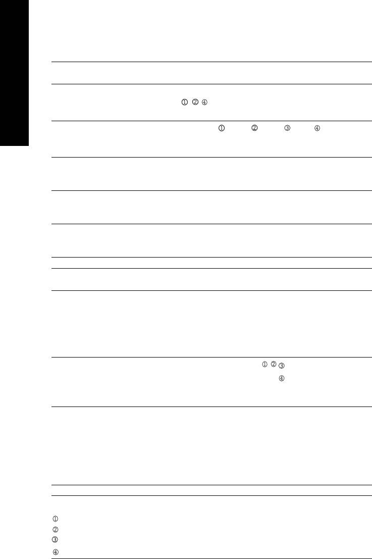
1-3-1 Installation of the CPU
Fig. 1
Fig. 2
Metal Lever
Gently lift the metal
Remove the plastic
lever located on the
covering on the CPU
CPU socket to the
socket.
upright position.
Fig. 3
Fig. 4
Notice the small gold
Once the CPU is
colored triangle
properly inserted,
located on the edge of
please replace the
the CPU socket.
load plate and
Align the
push the metal lever
indented corner of the
back into its original
CPU with the triangle and gently insert the CPU
position.
into position. (Grasping the CPU firmly between
your thumb and forefinger, carefully place it into
the socket in a straight and downwards motion.
Avoid twisting or bending motions that might cause
damage to the CPU during installation.)
GA-8I915ME Series Motherboard - 12 -
English
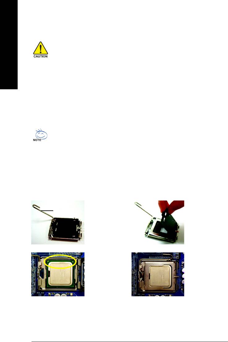
1-3-2 Installation of the Heatsink
Male Push Pin
The top of Female Push Pin
Female Push Pin
Fig.1
Fig. 2
Please apply an even layer of heatsink paste on
(Turning the push pin along the direction of arrow
the surface of the installed CPU.
is to remove the heatsink, on the contrary, is to
install.)Please note the direction of arrow sign on
the male push pin doesn't face inwards before
installation. (This instruction is only for Intel boxed
fan)
Fig. 3
Fig. 4
Place the heatsink atop the CPU and make sure
Please make sure the Male and Female push pin
the push pins aim to the pin hole on the
are joined closely. (for detailed installation
motherboard.Pressing down the push pins
instructions, please refer to the heatsink installation
diagonally.
section of the user manual)
Fig. 5
Fig. 6
Please check the back of motherboard after
Finally, please attach the power connector of the
installing. If the push pin is inserted as the picture,
heatsink to the CPU fan header located on the
the installation is complete.
motherboard.
The heatsink may adhere to the CPU as a result of hardening of the heatsink paste.To prevent
such an occurrence, it is suggested that either thermal tape rather than heat sink paste be used
for heat dissipation or using extreme care when removing the heatsink.
Hardware Installation- 13 -
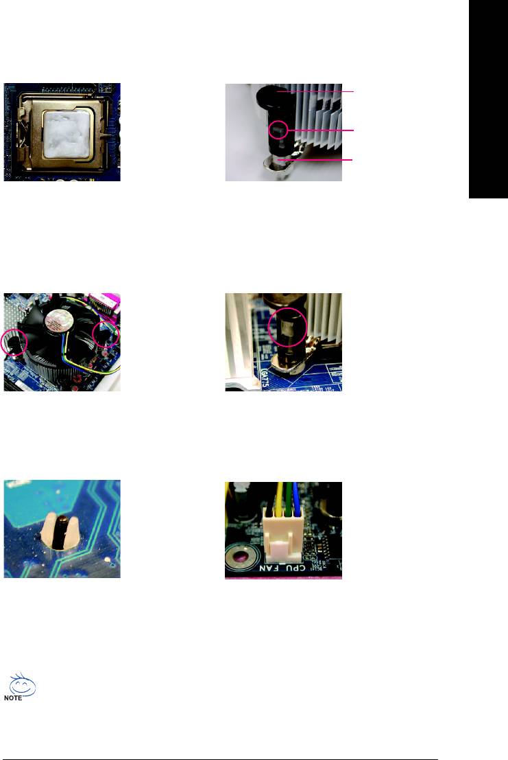
1-4 Installation of Memory
Before installing the memory modules, please comply with the following conditions:
1. Please make sure that the memory used is supported by the motherboard. It is
English
recommended that memory of similar capacity, specifications and brand be used.
2. Before installing or removing memory modules, please make sure that the computer
power is switched off to prevent hardware damage.
3. Memory modules have a foolproof insertion design. A memory module can be installed
in only one direction. If you are unable to insert the module, please switch the direction.
The motherboard supports DDR memory modules, whereby BIOS will automatically detect memory
capacity and specifications. Memory modules are designed so that they can be inserted only in one
direction. The memory capacity used can differ with each slot.
Notch
DDR
1. The DIMM slot has a notch, so the DIMM
memory module can only fit in one direction.
2. Insert the DIMM memory module vertically
into the DIMM slot. Then push it down.
3. Close the plastic clip at both edges of the DIMM
slots to lock the DIMM module.
Reverse the installation steps when you wish
to remove the DIMM module.
GA-8I915ME Series Motherboard - 14 -

Dual Channel DDR
English
GA-8I915ME-GV/GA-8I915ME-GL/GA-8I915ME-C/GA-8I915ME-G supports the Dual Channel
Technology. After operating the Dual Channel Technology, the bandwidth of Memory Bus will add
double.
GA-8I915ME-GV/GA-8I915ME-GL/GA-8I915ME-C/GA-8I915ME-G includes 2 DIMM sockets, and each
Channel has two DIMM sockets as following:
Channel A : DIMM1
Channel B : DIMM2
If you want to operate the Dual Channel Technology, please note the following explanations due
to the limitation of Intel chipset specifications.
1. If one DDR memory modules are installed: The Dual Channel Technolog cannot operate when
one DDR memory modules are installed.
2. If two DDR memory modules are installed, please use memory of the same storage capacity
in order to use dual channel memory and for BIOS to detect all the DDR memory modules.
We'll strongly recommend our user to slot two DDR memory modules into the DIMMs with the same
color in order for Dual Channel Technology to work.
Hardware Installation- 15 -
1-5 Installation of Expansion Cards
You can install your expansion card by following the steps outlined below:
1. Read the related expansion card's instruction document before install the expansion card into the
English
computer.
2. Remove your computer's chassis cover, screws and slot bracket from the computer.
3. Press the expansion card firmly into expansion slot in motherboard.
4. Be sure the metal contacts on the card are indeed seated in the slot.
5. Replace the screw to secure the slot bracket of the expansion card.
6. Replace your computer's chassis cover.
7. Power on the computer, if necessary, setup BIOS utility of expansion card from BIOS.
8. Install related driver from the operating system.
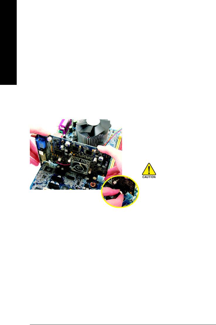
Installing a PCI Express x 16/G.E.A.R. expansion card:
Please carefully pull out the small white-
drawable bar at the end of the
PCI Express x 16/G.E.A.R. slot when
you try to install/Uninstall the VGA card.
Please align the VGA card to the onboard
PCI Express x 16/G.E.A.R. slot and press
firmly down on the slot .Make sure your
VGA card is locked by the small white-
drawable bar.
GA-8I915ME Series Motherboard - 16 -

English
1-5-1 What is G.E.A.R.?
The revolutionary and innovative G.E.A.R. (GIGABYTE Enhance AGP Riser) interface provides an
additional interface for traditional AGP Graphics card on Intel chipset based PCI Express solution
motherboard. It supports most of the AGP Graphics card available in the market from AGP 4X to AGP
8X graphics card.
Note:
1. Please remove the sticker on the G.E.A.R. slot before inserting your AGP graphics card.
2. G.E.A.R. interface is designed to provide a temporary AGP solution before the mass availability of
PCI Express graphics card. It is suggested to use PCI Express X 16 interface graphics card to avoid
the damage of your AGP graphics card.
3. G.E.A.R. interface is created through PCI interface signal and voltage switching to AGP interface,
due to this technical specification difference, it might cause AGP graphics card life-span shortens.
4. Please view the graphics cards support list currently validated by GIGABYTE enginneers. For more
updated information, please logon to GIGABYTE website at http://www.gigabyte.com.tw
1-5-2 Graphics Card Support List
(The items below are all supported under the Windows XP operating system. When using an
add-on graphics card, please first delete the onboard graphics driver before installing the driver
for the add-on graphics card.)
Figure 1-1. 4X AGP Card
Graphics Chip Maker Model Name
Nvidia Gigabyte GA-620
Gigabyte GA-622
Gigabyte GA-660 Plus
Gigabyte GA-GF2560
Gigabyte GA-GF2000
Gigabyte GA-GF1280
Gigabyte GV-GF2010D
Gigabyte GA-GF3000D
Gigabyte GV-GF1280-32E
Gigabyte GV-GF1280T-32P
Gigabyte G V-GF3200TF
Gigabyte G V-GF3500TF-GH
ELSA Gladiac Ultra
ELSA Gladiac 517
ELSA Gladiac 517vivo
ELSA Gladiac 525 A128
Leadtek W inFast A170 T H
Leadtek W inFast A250 TO
Leadtek W inFast A250 Ultra
To be continued...
Hardware Installation- 17 -
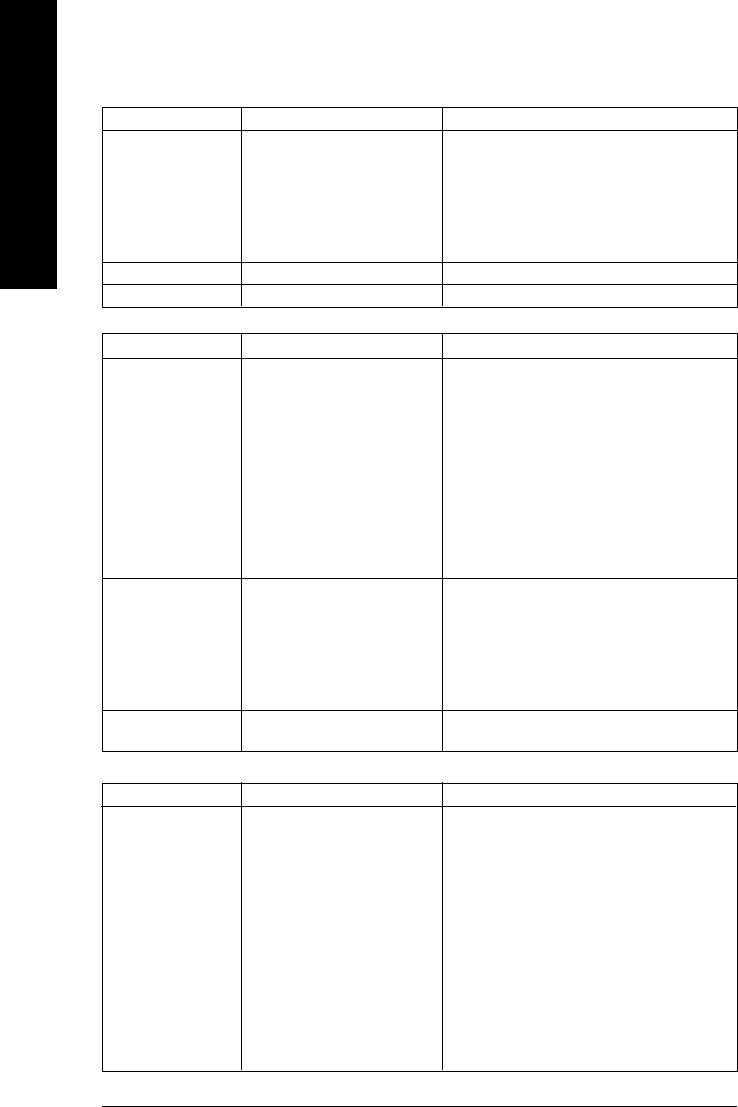
Figure 1-2. 4X AGP Card
Graphics Chip Maker Model Name
ATi Gigabyte GV-AR64DL-T-SI
Gigabyte GV-AR64S-H
English
Gigabyte GV-AP64D
Gigabyte GV-AP64DH
Gigabyte GV-AP128DG-H
Gigabyte GV-AF128D-GH
SiS Prolink SiS315 64MB
Savage ASUS V3500
Figure 2. 8X AGP Card
Graphics Chip Maker Model Name
Nvidia Gigabyte GV-N57L128D
Gigabyte G V-N59X128D
ASUS V9180TD
ASUS V9480-TVD
ASUS V9520
MSI MX440-VTD8X MS-8888
MSI Ti4600-TD-8X
Leadtek W inFast A280LE T D
Leadtek W inFast A310 T D
Albatron NVIDIA 5950
ATi Gigabyte GV-R9700 Pro
Gigabyte GV-R9700
Gigabyte GV-R9500
Gigabyte GV-R9200C3
Gigabyte G V-R98P128D
Gigabyte G V-R92P128VH
SiS Triplex Xabre Pro
Power Color Xabre 600 Pro
Figure 3. PCI Express x16 Card
Graphics Chip Maker Model Name
Nvidia Gigabyte GV-NX53128D
Gigabyte GV-NX57128D
Gigabyte GV-NX59128D
Gigabyte GV-NX62128D
Gigabyte GV-NX66256D
Gigabyte GV-NX66T128VP
Gigabyte G V-NX66T128D
Gigabyte G V-NX68T256DH
Gigabyte G V-NX55128DP
Gigabyte G V-NX68U256D
Gigabyte G V-NX62TC256D
ASUS EN6600/TD/128
To be continued...
GA-8I915ME Series Motherboard - 18 -

Figure 3. PCI Express x16 Card
English
Graphics Chip Maker Model Name
ATi Gigabyte GV-RX30S128D
Gigabyte GV-RX60P128D
Gigabyte GV-RX60X128V
Gigabyte GV-RX70128D
Gigabyte GV-RX70P128D
Gigabyte GV-RX80T256V
Gigabyte G V-RX80L256V
Gigabyte G V-RX80256D
ASUS AX800XT
ASUS AX700PRO
MSI RX600 XT-TD128
Hardware Installation- 19 -
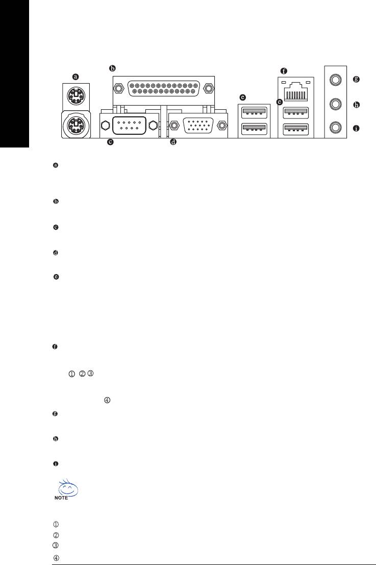
1-6 I/O Back Panel Introduction
English
PS/2 Keyboard and PS/2 Mouse Connector
To install a PS/2 port keyboard and mouse, plug the mouse to the upper port (green) and the
keyboard o the lower port (purple).
Parallel Port
The parallel port allows connection of a printer, scanner and other peripheral devices.
COM 1 (Serial Port)
Connects to serial-based mouse or data processing devices.
VGA Port
Monitor can be connected to VGA port.
USB port
Before you connect your device(s) into USB connector(s), please make sure your device(s) such
as USB keyboard, mouse, scanner, zip, speaker...etc. have a standard USB interface.
Also make sure your OS supports USB controller. If your OS does not support USB controller,
please contact OS vendor for possible patch or driver upgrade. For more information please
contact your OS or device(s) vendors.
LAN Port
The provided Internet connection is fast Ethernet, providing data transfer speeds of 10/100Mbps.
The provided Internet connection is Gigabit Ethernet, providing data transfer speeds of 10/100/
1000Mbps.
Line In
Devices like CD-ROM, walkman etc. can be connected to Line In jack.
Line Out
Connect the stereo speakers, earphone or front surround speakers to this connector.
MIC In
Microphone can be connected to MIC In jack.
You can use audio software to configure 2-/4-/6- channel audio functioning.
Only for GA-8I915ME-GV.
Only for GA-8I915ME-GL.
Only for GA-8I915ME-C.
Only for GA-8I915ME-G.
GA-8I915ME Series Motherboard - 20 -
English
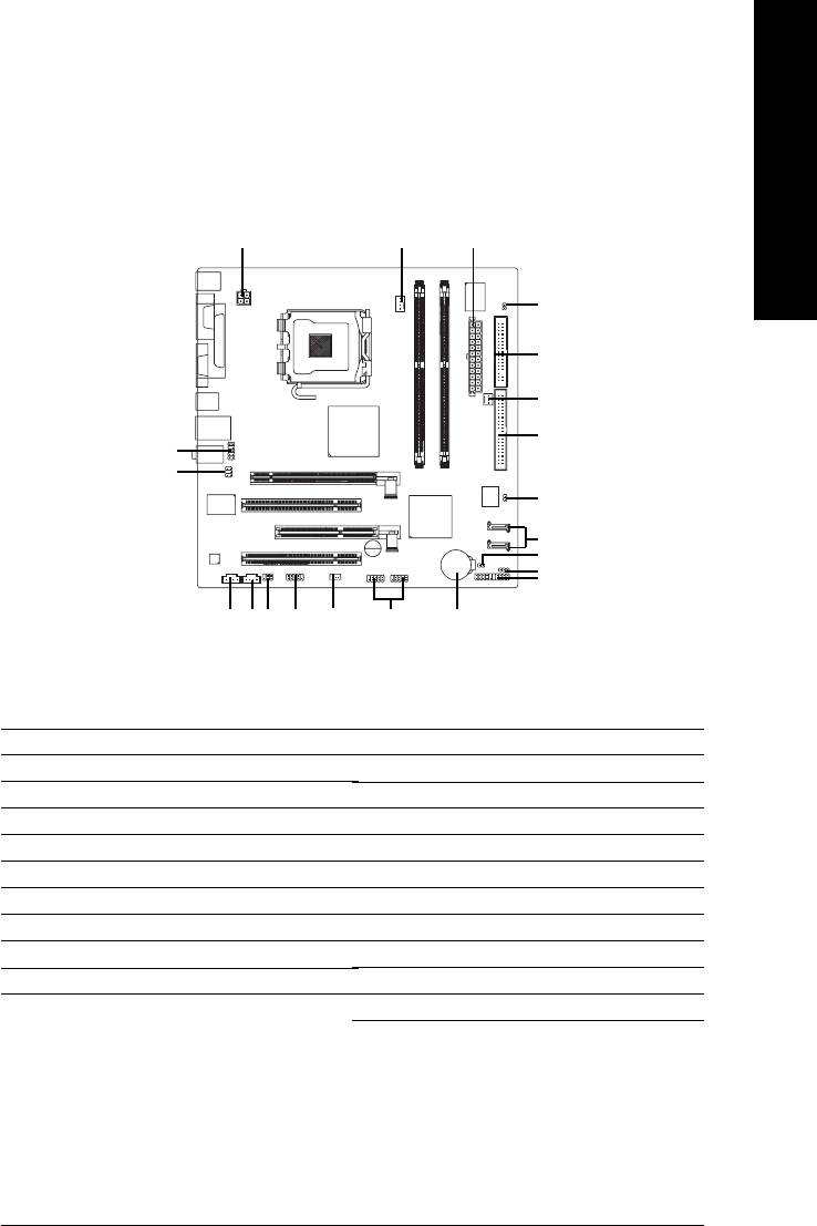
1-7 Connectors Introduction
13
2
18
5
4
6
11
16
20
7
19
10
8
12 15
13
17
9
14
21
1) ATX_12V
11) F_AUDIO
2) ATX (Power Connector)
12) CD_IN
3) CPU_FAN
13) AUX_IN
4) SYS_FAN
14) F_USB1 / F_USB2
5) FDD
15) COM2
6) IDE
16) SUR_CEN
7) SATA0 / SATA2
17) SPIDF_IO
8) F_PANEL
18) CI
9) WOL
19) CLR_CMOS
10) PWR_LED
20) BIOS_WP
21) BAT
Hardware Installation- 21 -
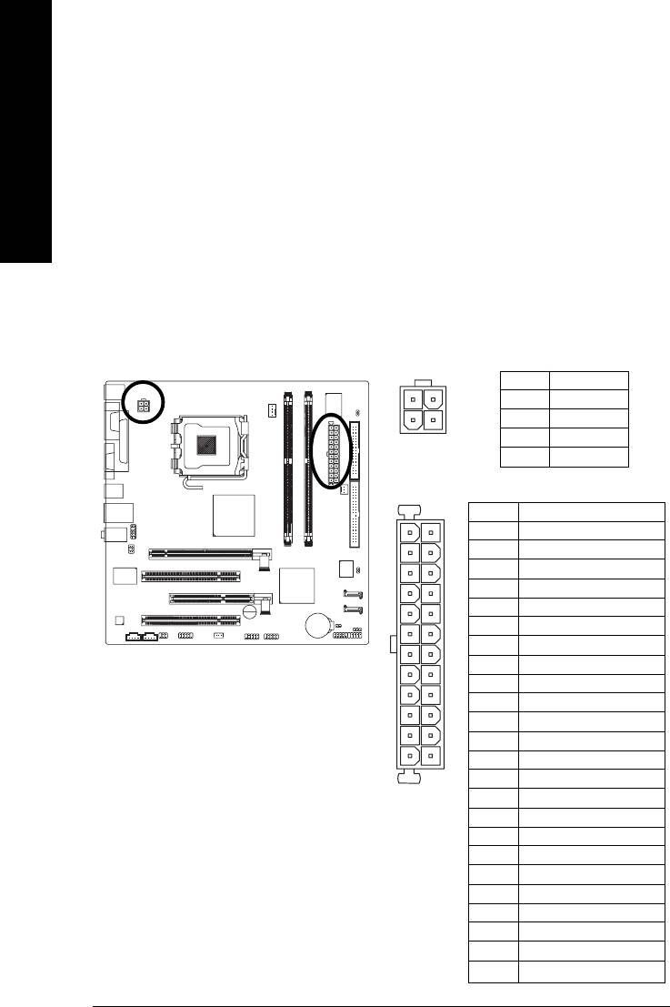
1/2) ATX_12V/ATX (Power Connector)
With the use of the power connector, the power supply can supply enough stable power to all the
components on the motherboard. Before connecting the power connector, please make sure that all
components and devices are properly installed. Align the power connector with its proper location on
English
the motherboard and connect tightly.
The ATX_12V power connector mainly supplies power to the CPU. If the ATX_12V power
connector is not connected, the system will not start.
Caution!
Please use a power supply that is able to handle the system voltage requirements. It is
recommended that a power supply that can withstand high power consumption be used (300W or
greater). If a power supply is used that does not provide the required power, the result can lead to an
unstable system or a system that is unable to start.
If you use a 24-pin ATX power supply, please remove the small cover on the power connector
on the motherboard before plugging in the power cord ; Otherwise, please do not remove it.
Pin No. Definition
3
4
1 GND
1
2
2 GND
3 +12V
4 +12V
Pin No. Definition
13
1
1 3.3V
2 3.3V
3 GND
4 +5V
5 GND
6 +5V
7 GND
8 Power Good
9 5V SB(stand by +5V)
10 +12V
11 +12V
12 3.3V(Only for 24pins ATX)
24
12
13 3.3V
14 -12V
15 GND
16 PS_ON(soft On/Off)
17 GND
18 GND
19 GND
20 -5V
21 +5V
22 +5V
23 +5V
24 GND
GA-8I915ME Series Motherboard - 22 -
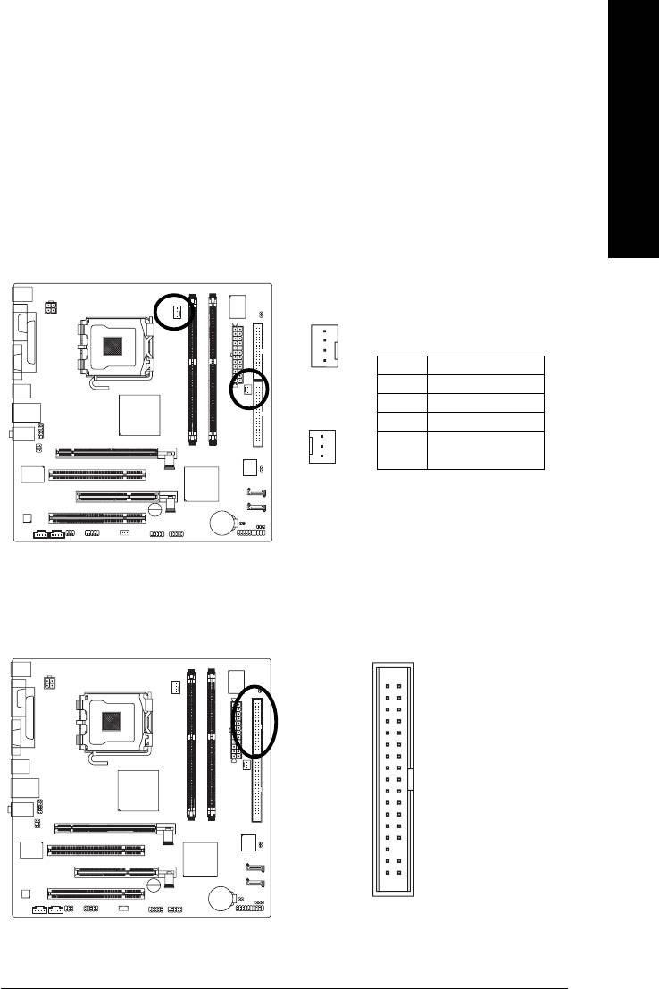
3/4) CPU_FAN / SYS_FAN (Cooler Fan Power Connector)
English
The cooler fan power connector supplies a +12V power voltage via a 3-pin/4-pin (only for
CPU_FAN) power connector and possesses a foolproof connection design.
Most coolers are designed with color-coded power connector wires. A red power connector
wireindicates a positive connection and requires a +12V power voltage. The black connector
wire is the ground wire (GND).
Please remember to connect the power to the cooler to prevent system overheating and
failure.
Caution!
Please remember to connect the power to the CPU fan to prevent CPU overheating and failure.
1
Pin No. Definition
1 GND
CPU_FAN
2 +12V
3 Sense
1
4 Speed Control
(Only for CPU_FAN)
SYS_FAN
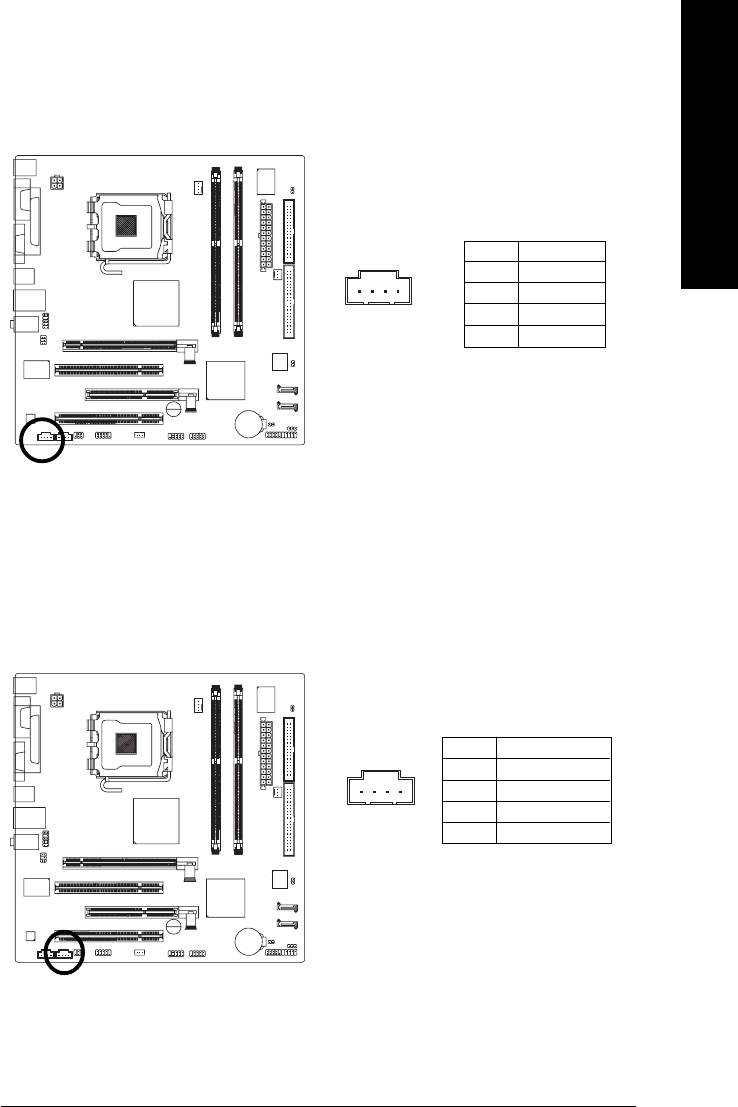
5) FDD (Floppy Connector)
The FDD connector is used to connect the FDD cable while the other end of the cable connects to the
FDD drive. The types of FDD drives supported are: 360KB, 720KB, 1.2MB, 1.44MB and 2.88MB.
Please connect the red power connector wire to the pin1 position.
34
33
2
1
Hardware Installation- 23 -
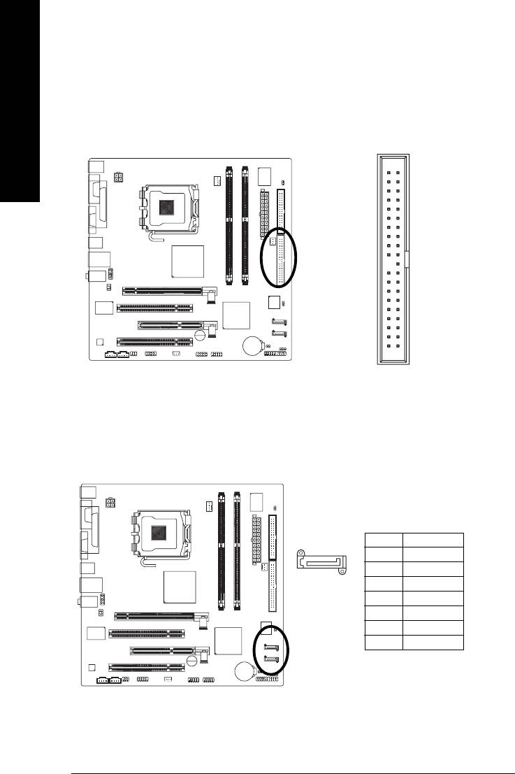
6) IDE (IDE Connector)
An IDE device connects to the computer via an IDE connector. One IDE connector can connect to one
IDE cable, and the single IDE cable can then connect to two IDE devices (hard drive or optical drive). If
you wish to connect two IDE devices, please set the jumper on one IDE device as Master and the other
English
as Slave (for information on settings, please refer to the instructions located on the IDE device).
3940
2
1
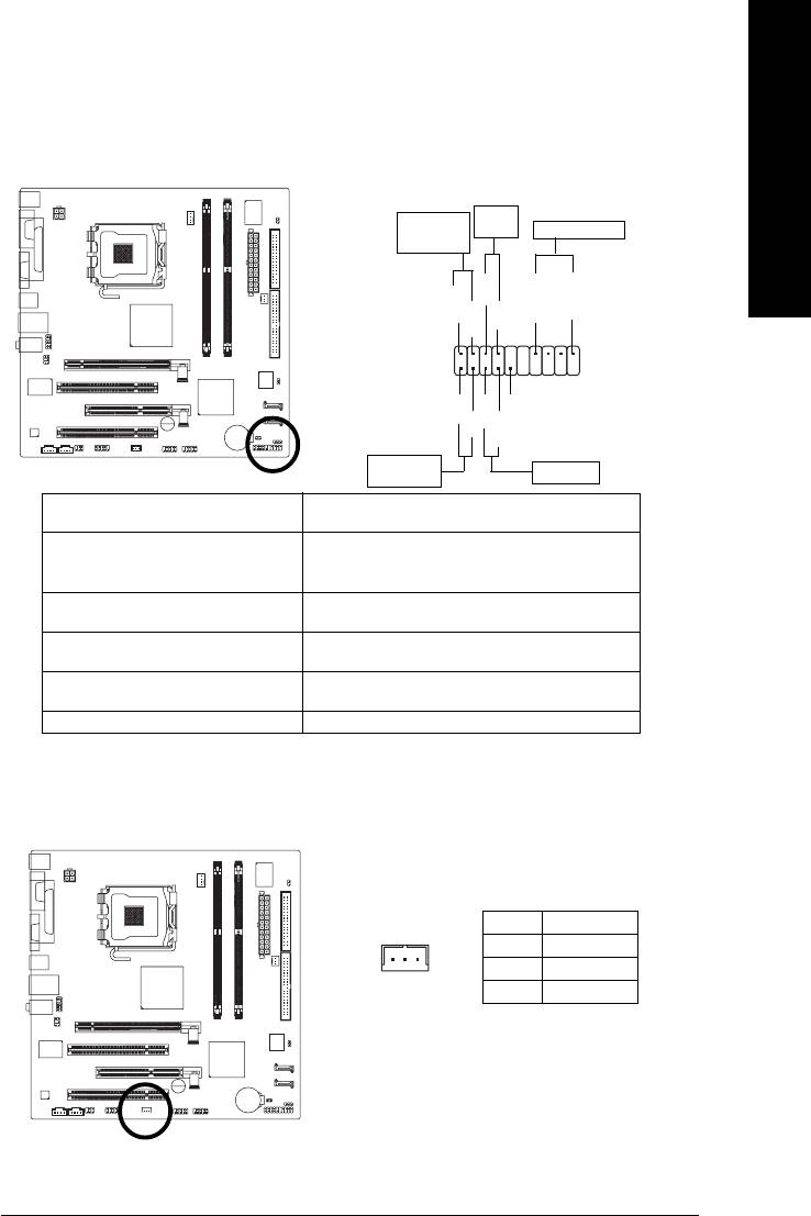
7) SATA0/SATA2 (Serial ATA Connector, Controlled by ICH6)
Serial ATA can provide up to 150MB/s transfer rate. Please refer to the BIOS setting for the
Serial ATA and install the proper driver in order to work properly.
Pin No. Definition
1 GND
1
7
2 TXP
3 TXN
4 GND
5 RXN
6 RXP
7 GND
GA-8I915ME Series Motherboard - 24 -
8) F_PANEL (Front Panel Jumper)
English
Please connect the power LED, PC speaker, reset switch and power switch etc of your chassis
front panel to the F_PANEL connector according to the pin assignment below.
Power
Message LED/
Switch
Power/
Speaker Connector
Sleep LED
PW+
SPEAK+
SPEAK-
MSG+
MSG-
PW-
2
20
1
19
HD+
RES-
NC
HD-
RES+
IDE Hard Disk
Reset Switch
Active LED
HD (IDE Hard Disk Active LED) Pin 1: LED anode(+)
Pin 2: LED cathode(-)
SPEAK (Speaker Connector) Pin 1: Power
Pin 2- Pin 3: NC
Pin 4: Data(-)
RES (Reset Switch) Open: Normal
Close: Reset Hardware System
PW (Power Switch) Open: Normal
Close: Power On/Off
MSG(Message LED/Power/Sleep LED) Pin 1: LED anode(+)
Pin 2: LED cathode(-)
NC NC
9) WOL (Wake On LAN)
Pin No. Definition
1 +5V SB
1
2 GND
3 Signal
Hardware Installation- 25 -
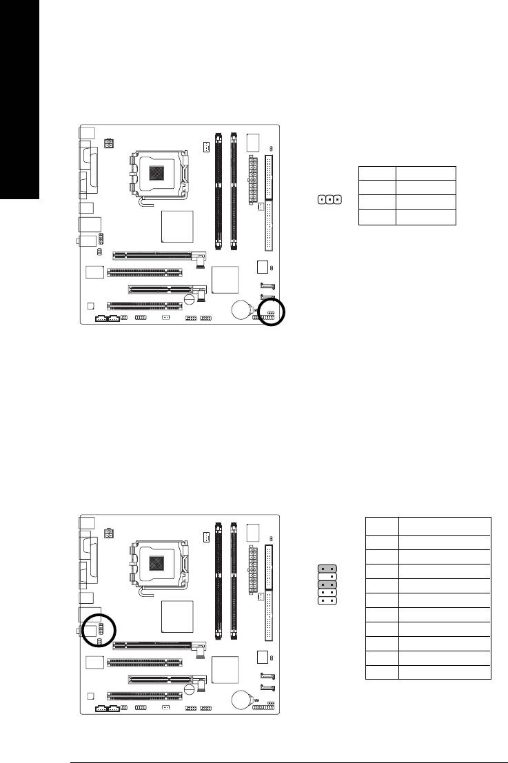
10) PWR_LED
PWR_LED is connect with the system power indicator to indicate whether the system is on/off. It
will blink when the system enters suspend mode.
English
Pin No. Definition
1 MPD+
1
2 MPD-
3 MPD-
11) F_AUDIO (Front Audio Connector)
Please make sure the pin assignments on the cable are the same as the pin assignments of the
F_AUDIO connector on the motherboard. To find out if the chassis you are buying support front
audio panel connector, please contact your dealer. If you want to use "Front Audio" connector, you
must remove the jumpers on pin 5-6, 9-10.
Pin No. Definition
1 MIC
2 GND
910
3 MIC_BIAS
4 POWER
12
5 FrontAudio(R)
6 Rear Audio (R)/ Return R
7NC
8 No Pin
9 FrontAudio (L)
10 Rear Audio (L)/ Return L
GA-8I915ME Series Motherboard - 26 -
12) CD_IN (CD IN)
English
Connect CD-ROM or DVD-ROM audio out to the connector.
Pin No. Definition
1 CD-L
1
2 GND
3 GND
4 CD -R
13) AUX_IN (AUX In Connector)
Connect other device (such as PCI TV Tuner audio out) to the connector.
Pin No. Definition
1 AUX-L
1
2 GND
3 GND
4 AUX-R
Hardware Installation- 27 -
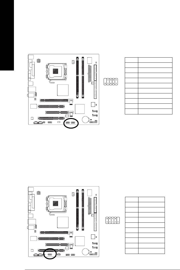
14) F_ USB1 / F_USB2 (Front USB Connector)
Be careful with the polarity of the front USB connector. Check the pin assignment carefully while
you connect the front USB cable, incorrect connection between the cable and connector will make
the device unable to work or even damage it. For optional front USB cable, please contact your
English
local dealer.
Pin No. Definition
1 Power
2 Power
9
1
3 USB DX-
4 USB Dy-
5 USB DX+
10
2
6 USB Dy+
7 GND
8 GND
9 No Pin
10 NC
15) COM2 (Serial Port Connector)
Be careful with the polarity of the COM connector. Check the pin assignment carefully while you
connect the COM cable, incorrect connection between the cable and connector will make the
device unable to work or even damage it. For optional COM cable, please contact your local
dealer.
Pin No. Definition
1 NDCD B-
2 NSIN B
2
10
3 NSOUT B
4 NDTR B-
5 GND
19
6 NDSR B-
7 NRTS B-
8 NCTS B-
9 NRI B-
10 No Pin
GA-8I915ME Series Motherboard - 28 -
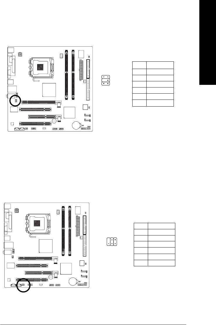
16) SUR_CEN
English
Please contact your nearest dealer for optional SUR_CEN cable.
Pin No. Definition
1 SUR OUTL
65
2 SUR OUTR
2
1
3 GND
4 No Pin
5 CENTER_OUT
6 BASS_OUT
17) SPDIF_IO (SPDIF In/ Out)
The SPDIF output is capable of providing digital audio to external speakers or compressed AC3
data to an external Dolby Digital Decoder. Use this feature only when your stereo system has
digital input function. Use SPDIF IN feature only when your device has digital output function.
Be careful with the polarity of the SPDIF_IO connector. Check the pin assignment carefully while
you connect the SPDIF_IO cable. Incorrect connection between the cable and connector will
make the device unable to work or even damage it. For optional SPDIF_IO cable, please contact
your local dealer.
Pin No. Definition
1 Power
2
6
2 No Pin
3 SPDIF
1
5
4 SPDIFI
5 GND
6 GND
Hardware Installation- 29 -
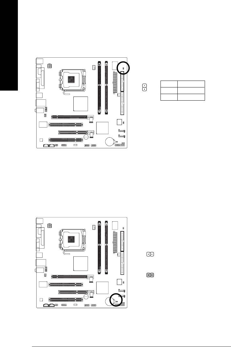
18) CI (Chassis Intrusion, Case Open)
This 2-pin connector allows your system to detect if the chassis cover is removed. You can check
the "Case Opened" status in BIOS Setup.
English
Pin No. Definition
1
1 Signal
2 GND
19) CLR_CMOS (Clear CMOS)
You may clear the CMOS data to its default values by this jumper. To clear CMOS, temporarily
short 1-2 pin. Default doesn't include the "Shunter" to prevent from improper use this jumper.
Open: Normal
1
1
Short :Clear CMOS
GA-8I915ME Series Motherboard - 30 -
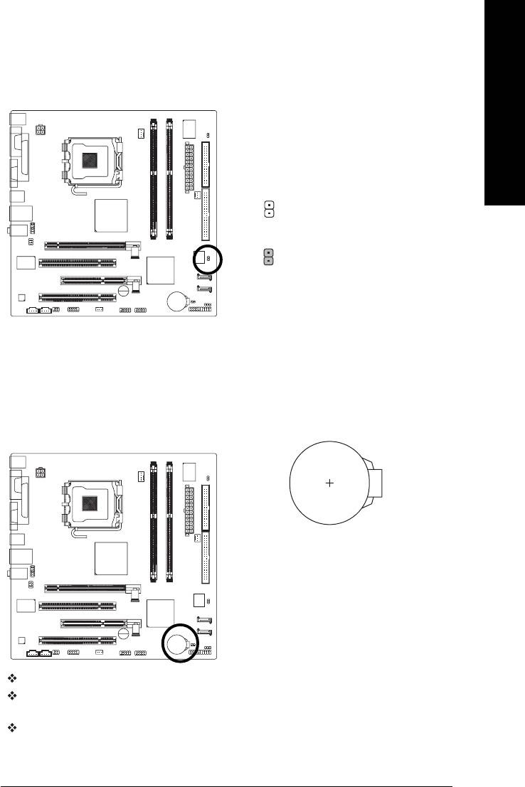
20) BIOS_WP (BIOS Write Protect)
English
1
Open: Normal
1
Short :Write Protect
21) BAT(Battery)
If you want to erase CMOS...
1.Turn OFF the computer and unplug the power cord.
2. Take out the battery gently and put it aside for about 10
minutes (Or you can use a metal object to connect the
positive and negative pins in the battery holder to make
them short for one minute).
3.Re-install the battery.
4.Plug the power cord and turn ON the computer.
Danger of explosion if battery is incorrectly replaced.
Replace only with the same or equivalent type
recommended by the manufacturer.
Dispose of used batteries according to the manufacturer's
instructions.
Hardware Installation- 31 -

English
GA-8I915ME Series Motherboard - 32 -
Оглавление
- GA-8I915ME Series Motherboard Layout
- Block Diagram
- Chapter 1 Hardware Installation
- Chapter 2 BIOS Setup
- Chapter 3 Install Drivers
- Chapter 4 Appendix


