Gigabyte GA-8I865PE-TW: Chapter 2 Hardware Installation Process
Chapter 2 Hardware Installation Process: Gigabyte GA-8I865PE-TW
English
Chapter 2 Hardware Installation Process
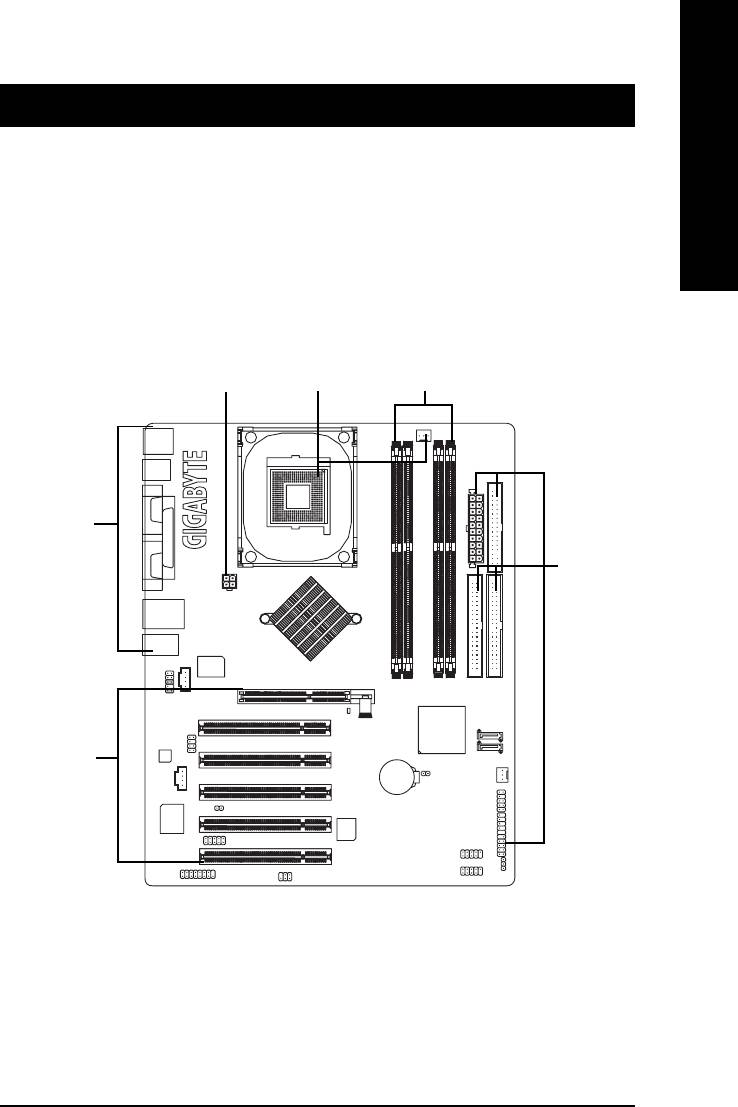
To set up your computer, you must complete the following steps:
Step 1- Install the Central Processing Unit (CPU)
Step 2- Install memory modules
Step 3- Install expansion cards
Step 4- Install I/O Peripherals Cables
Step 4
Step 1
Step 2
Step 4
Step 4
Step 3
Congratulations you have accomplished the hardware installation!
Turn on the power supply or connect the power cable to the power outlet. Continue with
the BIOS/software installation.
- 9 - Hardware Installation Process
Step 1: Install the Central Processing Unit (CPU)
Before installing the processor, adhere to the following warning:
1. Please make sure that the motherboard supports the CPU.
2. Please take note of the one indented corner of the CPU. If you install the CPU in the wrong
English
direction, the CPU will not insert properly. If this occurs, please change the insert direction of
the CPU.
3. Please add an even layer of heat sink paste between the CPU and heatsink.
4. Please make sure the heatsink is installed on the CPU prior to system use, otherwise
overheating and permanent damage of the CPU may occur.
5. Please set the CPU host frequency in accordance with the processor specifications. It is not
recommended that the system bus frequency be set beyond hardware specifications since
it does not meet the required standards for the peripherals. If you wish to set the frequency
beyond the proper specifications, please do so according to your hardware specifications
including the CPU, graphics card, memory, hard drive, etc.
HT functionality requirement content :
Enabling the functionality of Hyper-Threading Technology for your computer system requires all
of the following platform components:
®
®
- CPU: An Intel
Pentium
4 Processor with HT Technology
®
- Chipset: An Intel
Chipset that supports HT Technology
- BIOS: A BIOS that supports HT Technology and has it enabled
- OS: An operation system that has optimizations for HT Technology
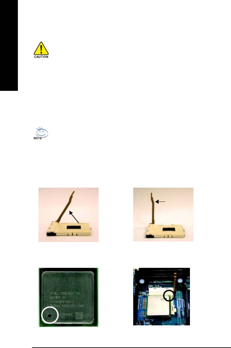
Step 1-1: CPU Installation
Socket
Angling the
Actuation
0
rod to 65
Lever
1. Angling the rod to 65-degree maybe feel a
2. Pull the rod to the 90-degree directly.
kind of tight, and then continue pull the rod
to 90-degree when "click" noise is heard.
Pin1 indicator
Pin1 indicator
4. Locate Pin 1 in the socket and look for a (golden)
3. CPU Top View
cut edge on the CPU upper corner. Then insert
the CPU into the socket.
- 10 -GA-8I865PE-TW Motherboard
English
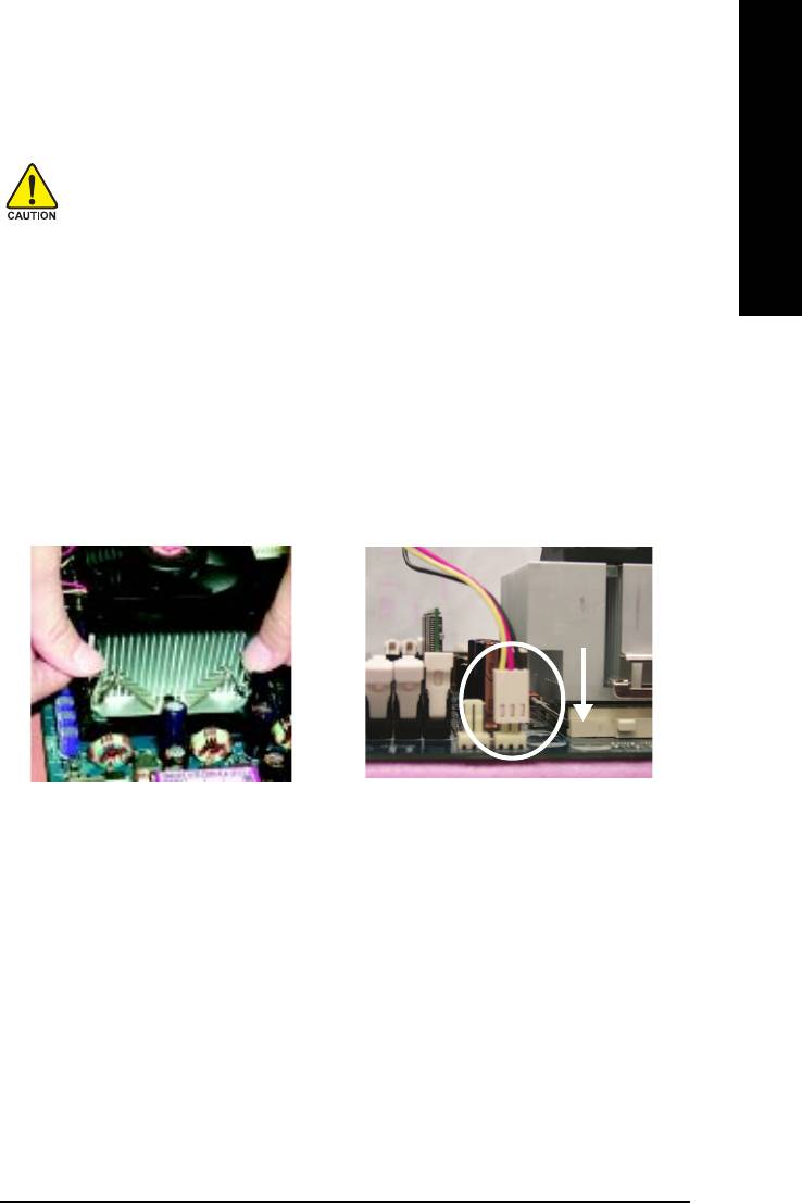
Step 1-2 : CPU Cooling Fan Installation
Before installing the CPU cooling fan, adhere to the following warning:
1. Please use Intel approved cooling fan.
2. We recommend you to apply the thermal tape to provide better heat conduction
between your CPU and cooling fan.
(The CPU cooling fan might stick to the CPU due to the hardening of the thermal
paste. During this condition if you try to remove the cooling fan, you might pull the
processor out of the CPU socket alone with the cooling fan, and might damage the
processor. To avoid this from happening, we suggest you to either use thermal tape
instead of thermal paste, or remove the cooling fan with extreme caution.)
3. Make sure the CPU fan power cable is plugged in to the CPU fan connector, this
completes the installation.
Please refer to CPU cooling fan user's manual for more detail installation procedure.
2. Make sure the CPU fan is plugged to the
1. Fasten the cooling fan supporting-base
CPU fan connector, than install completely.
onto the CPU socket on the motherboard.
- 11 - Hardware Installation Process
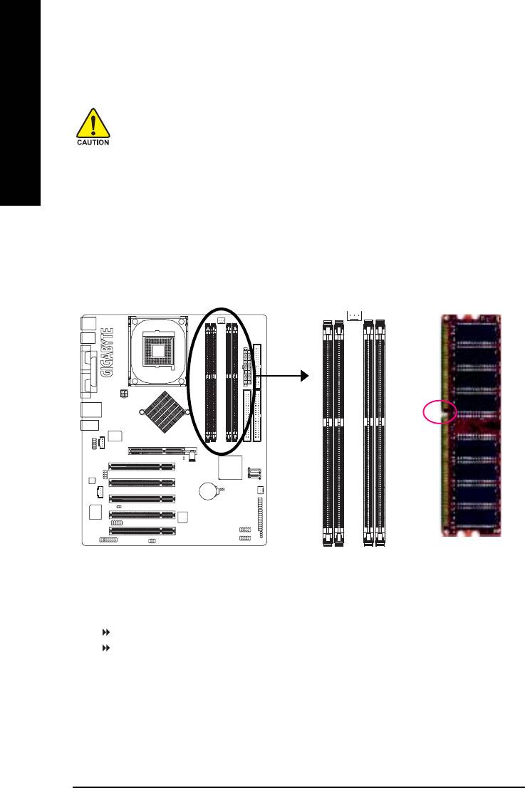
Step 2: Install memory modules
Before installing the memory modules, please comply with the following conditions:
1. Please make sure that the memory used is supported by the motherboard. It is
English
recommended that memory of similar capacity, specifications and brand be used.
2. Before installing or removing memory modules, please make sure that the computer
power is switched off to prevent hardware damage.
3. Memory modules have a foolproof insertion design. A memory module can be in-
stalled in only one direction. If you are unable to insert the module, please switch
the direction.
The motherboard supports DDR memory modules, whereby BIOS will automatically detect memory
capacity and specifications. Memory modules are designed so that they can be inserted only in
one direction. The memory capacity used can differ with each slot.
Notch
DDR
GA-8I865PE-TW supports the Dual Channel Technology. After operating the Dual Channel Technology,
the bandwidth of Memory Bus will add double up to 6.4GB/s.
GA-8I865PE-TW includes 4 DIMM sockets, and each Channel has two DIMM sockets as following:
Channel A : DDR 1, DDR 2
Channel B : DDR 3, DDR 4
If you want to operate the Dual Channel Technology, please note the following explanations due to the
®
limitation of Intel
chipset specifications.
1. Only one DDR memory module is installed: The Dual Channel Technology can't operate when only
one DDR memory module is installed.
2. Two DDR memory modules are installed (the same memory size and type): The Dual Channel
Technology will operate when two memory modules are inserted individually into Channel A and B. If
you install two memory modules in the same channel, the Dual Channel Technology will not operate.
- 12 -GA-8I865PE-TW Motherboard
English
3. Three DDR memory modules are installed: Please note that The Dual Channel Technology will not
operate when three DDR memory modules are installed; part of them will not be detected.
4. Four DDR memory modules are installed: If you install four memory modules at the same time, the
Dual Channel Technology will operate only when those modules have the same memory size and
type.
We'll strongly recommend our user to slot two DDR memory modules into the DIMMs with the
same color in order for Dual Channel Technology to work.
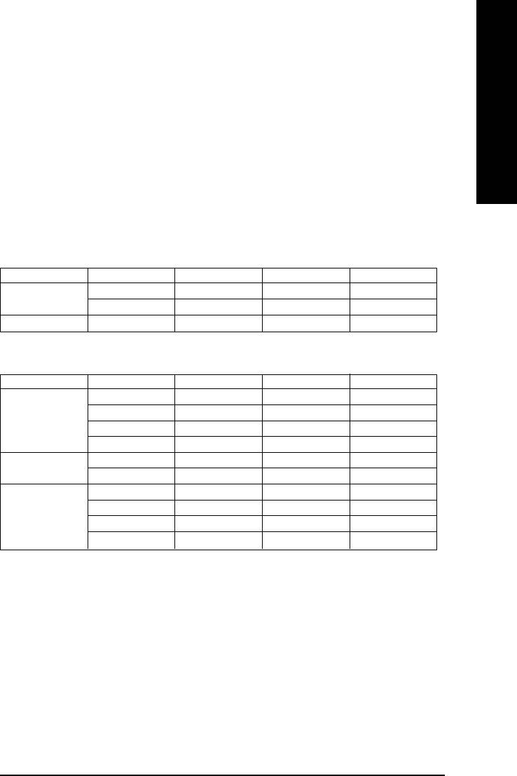
The following tables include all memory-installed combination types:
(Please note that those types not in the tables will not boot up.)
z Figure 1: Dual Channel Technology (DS: Double Side, SS: Single Side)
DDR 1 DDR 2 DDR 3 DDR 4
2 memory modules
DS/SS X DS/SS X
X DS/SS X DS/SS
4 memory modules
DS/SS DS/SS DS/SS DS/SS
z Figure 2: Don't operate Dual Channel Technology (DS: Double Side, SS: Single Side)
DDR 1 DDR 2 DDR 3 DDR 4
1 memory module
DS/SS X X X
X DS/SS X X
X X DS/SS X
X X X DS/SS
2 memory modules
DS/SS DS/SS X X
X X DS/SS DS/SS
3 memory modules
DS/SS DS/SS DS/SS X
DS/SS DS/SS X DS/SS
DS/SS X DS/SS DS/SS
X DS/SS DS/SS DS/SS
- 13 - Hardware Installation Process
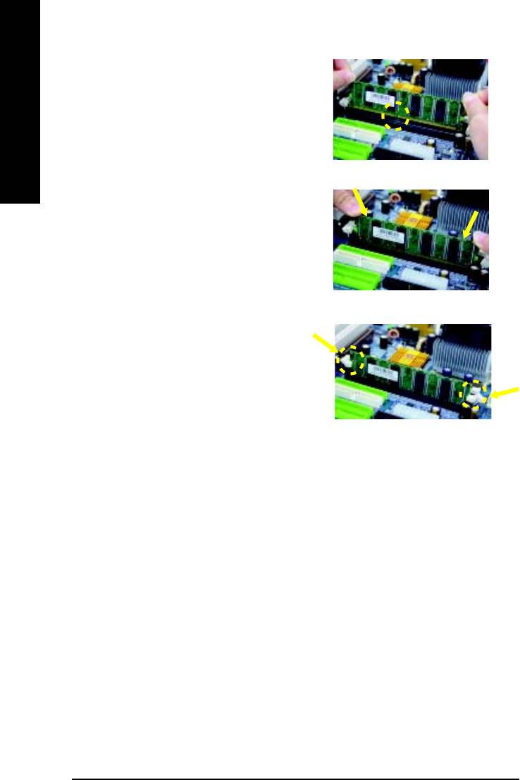
1. The DIMM slot has a notch, so the DIMM
memory module can only fit in one direction.
English
2. Insert the DIMM memory module vertically into
the DIMM slot. Then push it down.
3. Close the plastic clip at both edges of the DIMM
slots to lock the DIMM module.
Reverse the installation steps when you wish
to remove the DIMM module.
DDR Introduction
Established on the existing SDRAM infrastructure, DDR (Double Data Rate) memory is a high
performance and cost-effective solution that allows easy adoption for memory vendors, OEMs,
and system integrators.
DDR memory is a great evolutionary solution for the PC industry that builds on the existing
SDRAM architecture, yet make the awesome advances in solving the system performance
bottleneck by doubling the memory bandwidth. Nowadays, with the highest bandwidth of 3.2GB/
s of DDR400 memory and complete line of DDR400/333/266/200 memory solutions, DDR memory
is the best choice for building high performance and low latency DRAM subsystem that are
suitable for servers, workstations, and full range of desktop PCs.
- 14 -GA-8I865PE-TW Motherboard
English
Step 3: Install expansion cards
1. Read the related expansion card's instruction document before install the expansion card into
the computer.
2. Remove your computer's chassis cover, necessary screws and slot bracket from the computer.
3. Press the expansion card firmly into expansion slot in motherboard.
4. Be sure the metal contacts on the card are indeed seated in the slot.
5. Replace the screw to secure the slot bracket of the expansion card.
6. Replace your computer's chassis cover.
7. Power on the computer, if necessary, setup BIOS utility of expansion card from BIOS.
8. Install related driver from the operating system.
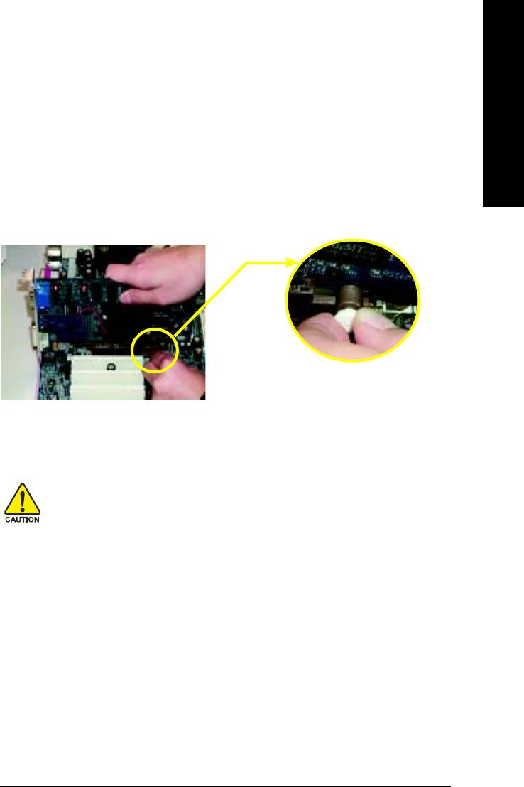
Please carefully pull out the small white- drawable bar
at the end of the AGP slot when you try to install/
Uninstall the AGP card. Please align the AGP card to
AGP Card
the onboard AGP slot and press firmly down on the slot
.Make sure your AGP card is locked by the small white-
drawable bar.
When an AGP 2x (3.3V) card is installed the 2X_DET will light up, indicating a non-supported
graphics card is inserted. Informing users that system might not boot up normally due to AGP 2x
(3.3V) is not supported by the chipset.
- 15 - Hardware Installation Process
Step 4: Install I/O Peripherals Cables
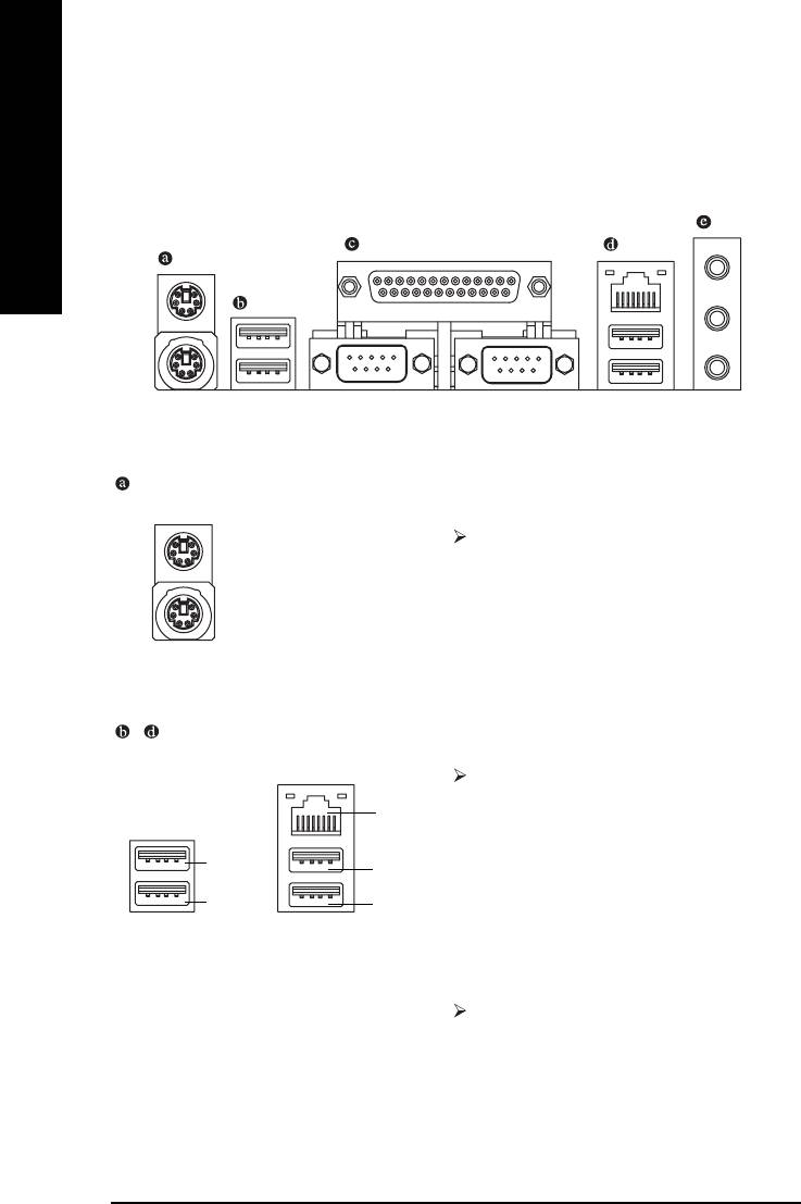
Step 4-1: I/O Back Panel Introduction
English
PS/2 Keyboard and PS/2 Mouse Connector
PS/2 Mouse Connector
To install a PS/2 port keyboard and mouse, plug
(6 pin Female)
the mouse to the upper port (green) and the key-
board to the lower port (purple).
PS/2 Keyboard Connector
(6 pin Female)
/ USB/LAN Connector
Before you connect your device(s) into USB
connector(s), please make sure your device(s) such
LAN
as USB keyboard, mouse, scanner, zip, speaker...
etc. have a standard USB interface. Also make sure
USB 3
USB 4
your OS supports USB controller. If your OS does
USB 2
USB 5
not support USB controller, please contact OS
vendor for possible patch or driver upgrade. For
more information please contact your OS or device(s)
vendors.
The provided Internet connection is Gigabit
Ethernet, providing data transfer speeds of 10/100/
1000Mbps.
- 16 -GA-8I865PE-TW Motherboard
English
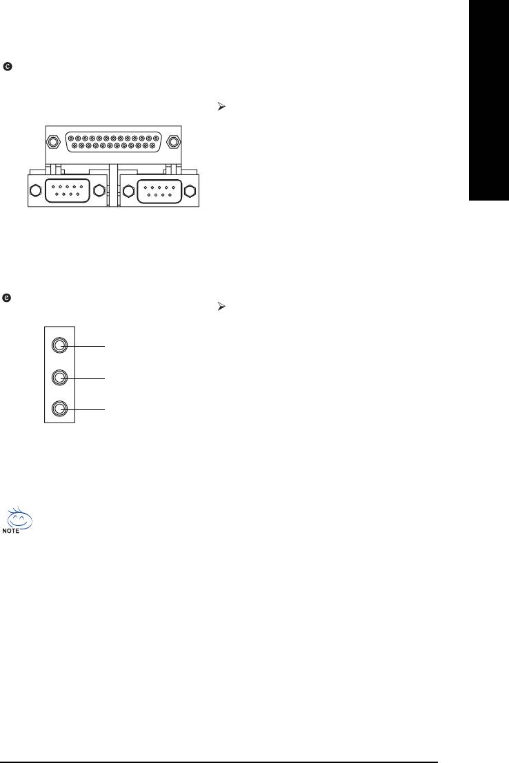
Parallel Port, Serial Ports (COMA / COMB)
Parallel Port
According to your motherboard, please see the
(25 pin Female)
following descriptions for the devices. The parallel
port allows connection of a printer, scanner and
other peripheral devices. Mouse and modem etc.
can be connected to Serial ports.
COMA
COMB
Serial Port (9 pin Male)
Audio Connectors
After install onboard audio driver, you may
connect speaker to Line Out jack, microphone to
MIC In jack. Devices like CD-ROM, walkman etc.
Line In
can be connected to Line In jack.
Please note:
Line Out
You can use audio software to configure 2-/4-/6-/
8-channel audio functioning. If you wish to use 8
MIC In
channel audio, a SUR_CEN cable is required
(select desired setup) along with proper software
configuration. Please contact your nearest dealer
for purchase of a SUR_CEN cable.
If you want the detailed information for 2-/4-/6-/8-channel audio setup
installation, please refer to page 61.
- 17 - Hardware Installation Process
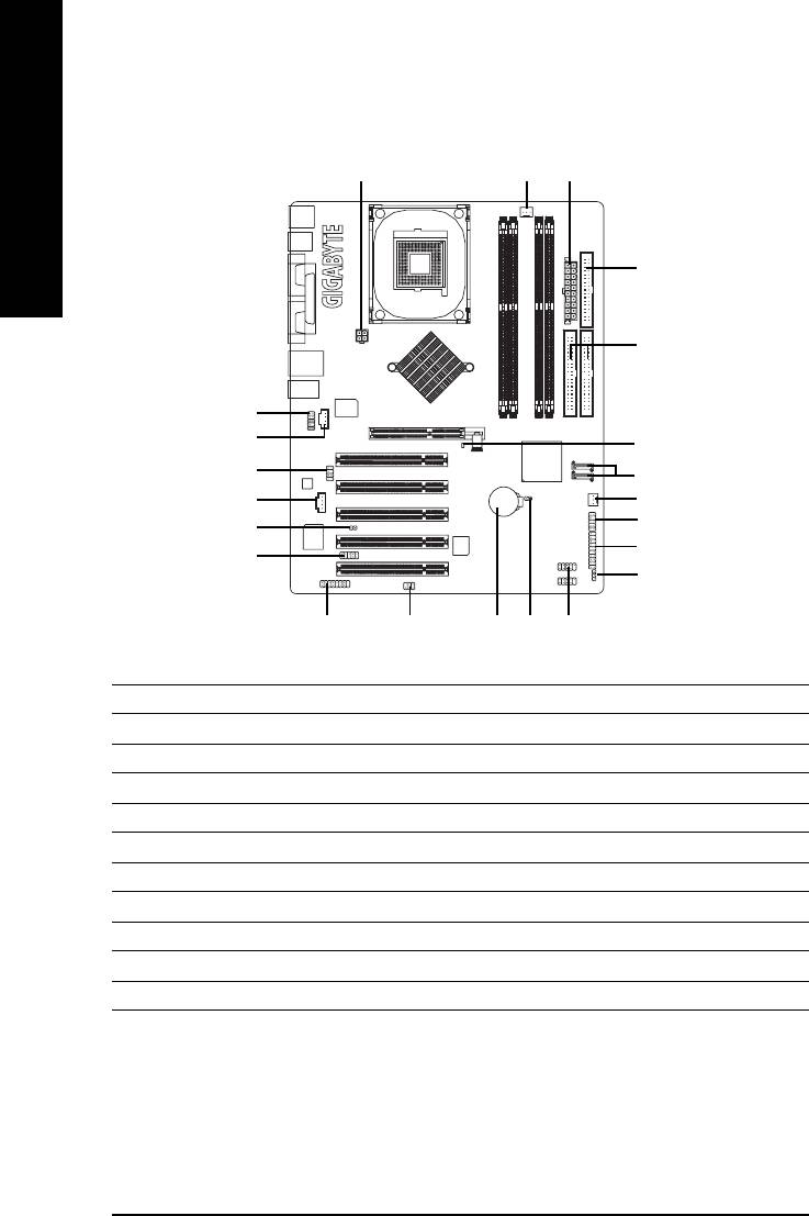
Step 4-2: Connectors & Jumper Setting Introduction
1
3
2
English
5
6
12
14
8
13
7
15
4
20
21
10
17
9
19
16
11
22
18
1) ATX_12V
12) F_AUDIO
2) ATX (Power Connector)
13) SUR_CEN
3) CPU_FAN
14) CD_IN
4) SYS_FAN
15) AUX_IN
5) FDD
16) SPDIF_IO
6) IDE1 / IDE2
17) IR_CIR
7) SATA0 / SATA1
18) F_USB1 / F_USB2
8) 2X_DET
19) GAME
9) PWR_LED
20) INFO_LINK
10) F_PANEL
21) CI
11) BAT
22) CLR_CMOS
- 18 -GA-8I865PE-TW Motherboard
English
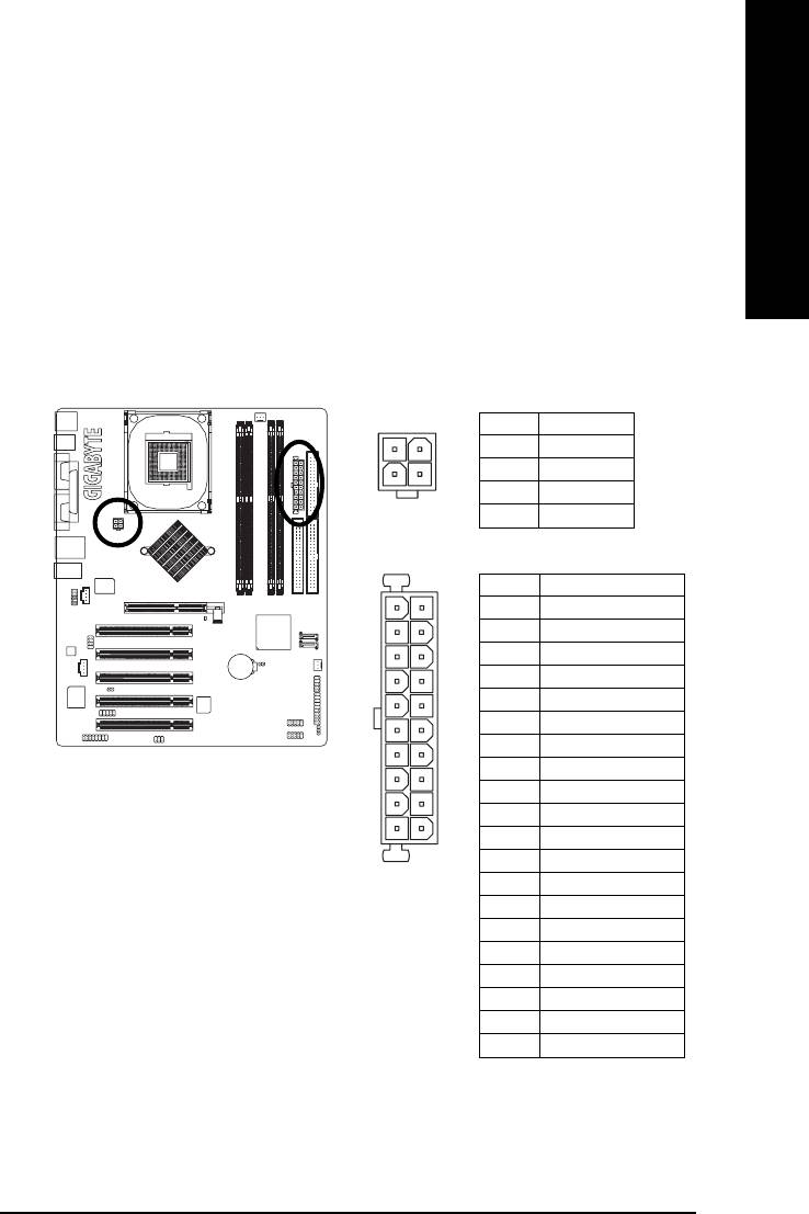
1/2) ATX_12V/ATX (Power Connector)
With the use of the power connector, the power supply can supply enough stable power to all the
components on the motherboard. Before connecting the power connector, please make sure that all
components and devices are properly installed. Align the power connector with its proper location on
the motherboard and connect tightly.
The ATX_12V power connector mainly supplies power to the CPU. If the ATX_12V power connector
is not connected, the system will not start.
Caution!
Please use a power supply that is able to handle the system voltage requirements. It is
recommended that a power supply that can withstand high power consumption be used (300W or
greater). If a power supply is used that does not provide the required power, the result can lead to an
unstable system or a system that is unable to start.
Pin No. Definition
2
1
1 GND
2 GND
4
3
3 +12V
4 +12V
Pin No. Definition
11
1
1 3.3V
2 3.3V
3 GND
4 VCC
5 GND
6 VCC
7 GND
8 Power Good
9 5V SB(stand by +5V)
10 +12V
20
10
11 3.3V
12 -12V
13 GND
14 PS_ON(softOn/Off)
15 GND
16 GND
17 GND
18 -5V
19 VCC
20 VCC
- 19 - Hardware Installation Process
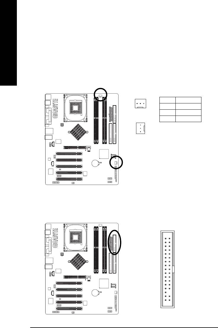
3/4) CPU_FAN / SYS_FAN (Cooler Fan Power Connector)
The cooler fan power connector supplies a +12V power voltage via a 3-pin power connector and
possesses a ful-proof connection design.
Most coolers are designed with color-coded power connector wires. A red power connector wire
English
indicates a positive connection and requires a +12V power voltage. The black connector wire is the
ground wire (GND).
Please remember to connect the power to the cooler to prevent system overheating and failure.
Caution!
Please remember to connect the power to the CPU fan to prevent CPU overheating and failure.
Pin No. Definition
1
1 GND
CPU_FAN
2 +12V
3 Sense
1
SYS_FAN
5) FDD (FDD Connector)
The FDD connector is used to connect the FDD cable while the other end of the cable connects to the
FDD drive. The types of FDD drives supported are: 360KB, 720KB, 1.2MB, 1.44MB and 2.88MB.
Please connect the red power connector wire to the pin1 position.
34
33
2
1
- 20 -GA-8I865PE-TW Motherboard
English
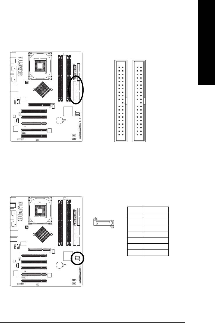
6) IDE1/ IDE2 (IDE1/IDE2 Connector)
Please connect first hard disk to IDE1 and connect CDROM to IDE2. The red stripe of the ribbon cable
must be the same side with the Pin1.
40
39
2
1
IDE1IDE2
7) SATA0/SATA1 (Serial ATA Connector)
You can connect the Serial ATA device to this connector.
Pin No. Definition
1 GND
7
2 TXP
1
3 TXN
4 GND
5 RXN
6 RXP
7 GND
- 21 - Hardware Installation Process
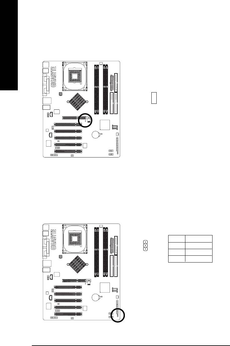
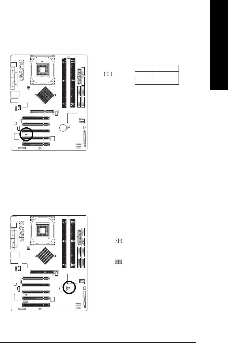
8) 2X_DET
When an AGP 2X (3.3V) card is installed the 2X_DET will light up, indicating a nonsupported graphics
card is inserted. Informing users that system might not boot up normally due to AGP 2X (3.3V) is not
supported by the chipset.
English
-
+
9) PWR_LED
PWR_LED is connect with the system power indicator to indicate whether the system is on/off. It will
blink when the system enters suspend mode. If you use dual color LED, power LED will turn to another
color.
Pin No. Definition
1 MPD+
2 MPD-
1
3 MPD-
- 22 -GA-8I865PE-TW Motherboard
English
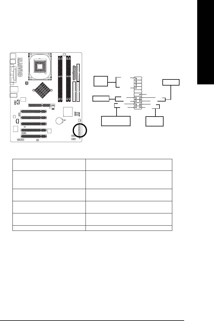
10) F_PANEL (2x10 pins connector)
Please connect the power LED, PC peaker, reset switch and power switch etc. of your chassis front panel
to the F_PANEL connector according to the pin assignment below.
20
19
SPEAK-
Speaker
Reset Switch
Connector
SPEAK+
NC
PW-
Power Switch
RES+
PW+
RES-
MSG-
HD-
MSG+
HD+
2
1
Message LED/Power/
IDE Hard Disk
Sleep LED
Active LED
HD (IDE Hard Disk Active LED) Pin 1: LED anode(+)
(Blue) Pin 2: LED cathode(-)
SPEAK (Speaker Connector) Pin 1: VCC(+)
(Amber) Pin 2- Pin 3: NC
Pin 4: Data(-)
RES (Reset Switch) Open: Normal Operation
(Green) Close: Reset Hardware System
PW (Power Switch) Open: Normal Operation
(Red) Close: Power On/Off
MSG (Message LED/ Power/ Sleep LED) Pin 1: LED anode(+)
(Yellow) Pin 2: LED cathode(-)
NC ( Purple) NC
- 23 - Hardware Installation Process
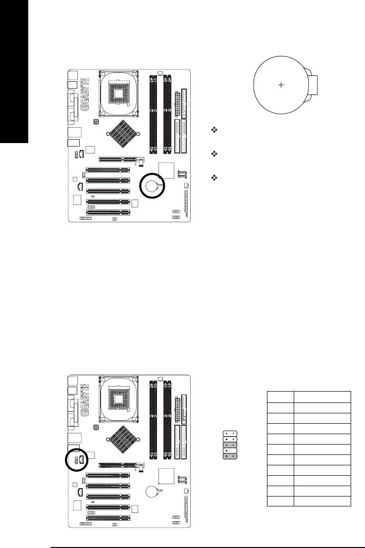
11) BAT (Battery)
English
Danger of explosion if battery is incorrectly
replaced.
Replace only with the same or equivalent type
recommended by the manufacturer.
Dispose of used batteries according to the
manufacturer's instructions.
If you want to erase CMOS...
1. Please turn off the computer and unplug the
power.
2. Remove the battery, wait for 30 second.
3. Re-install the battery.
4. Plug the power cord and turn on the computer.
12) F_AUDIO (Front Audio Connector)
If you want to use Front Audio connector, you must remove 5-6, 9-10 Jumper. In order to utilize the
front audio header, your chassis must have front audio connector. Also please make sure the pin
assigment on the cable is the same as the pin assigment on the MB header. To find out if the chassis
you are buying support front audio connector, please contact your dealer.Please note, you can have
the alternative of using front audio connector or of using rear audio connector to play sound.
Pin No. Definition
1 MIC
2 GND
12
3 MIC_BIAS
4 Power
5 Front Audio (R)
6 Rear Audio (R)
109
7 Reserved
8 No Pin
9 Front Audio (L)
10 Rear Audio (L)
- 24 -GA-8I865PE-TW Motherboard
English
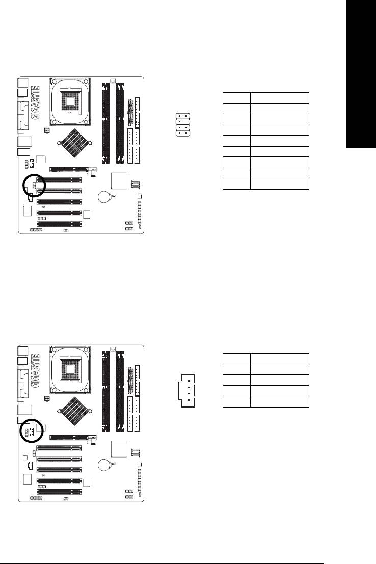
13) SUR_CEN (Surround Center Connector)
Please contact your nearest dealer for optional SUR_CEN cable.
Pin No. Definition
1
2
1 SUR OUTL
2 SUR OUTR
3 GND
78
4 No Pin
5 CENTER_OUT
6 BASS_OUT
7 AUX_L
8 AUX_R
14) CD_IN (CD In Connector)
Connect CD-ROM or DVD-ROM audio out to the connector.
Pin No. Definition
1
1 CD-L
2 GND
3 GND
4 CD-R
- 25 - Hardware Installation Process
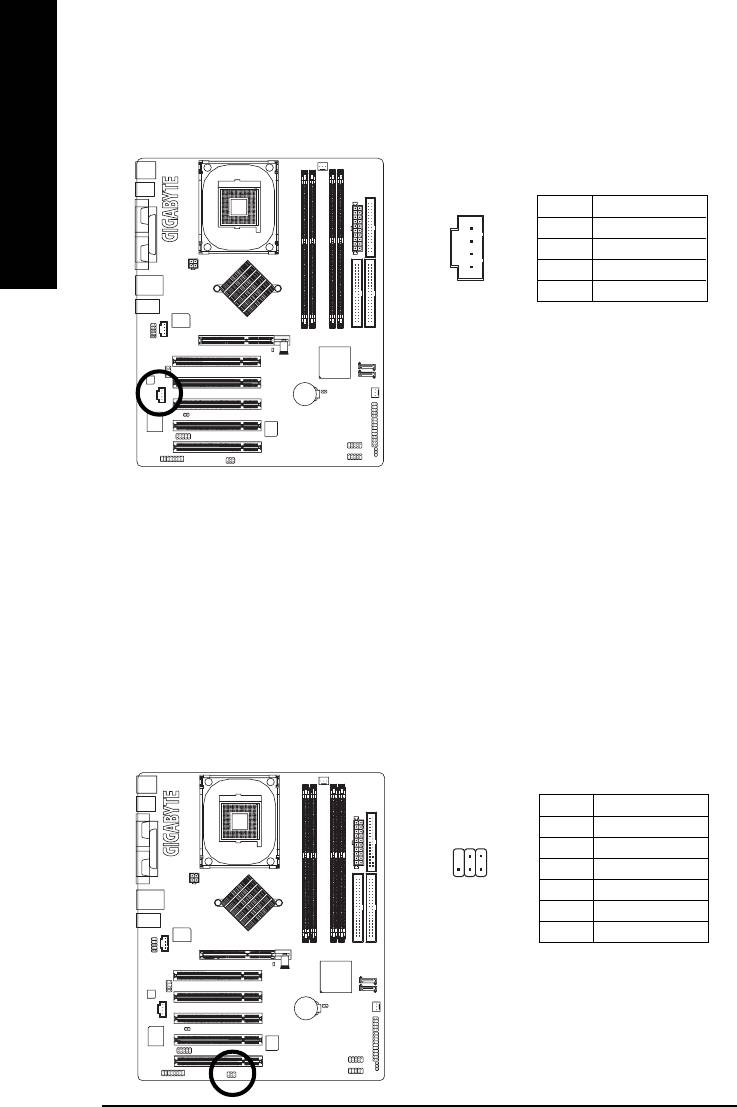
15) AUX_IN (AUX In Connector)
Connect other device (such as PCI TV Tunner audio out) to the connector.
English
1
Pin No. Definition
1 AUX-L
2 GND
3 GND
4 AUX-R
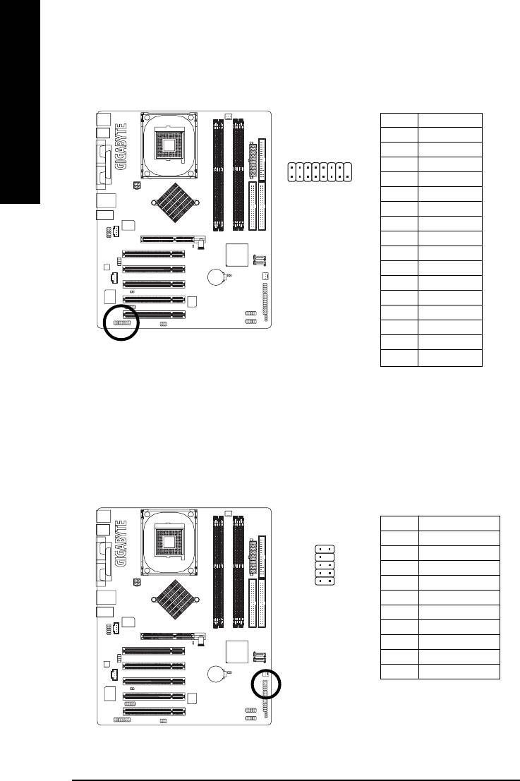
16) SPDIF_IO (SPDIF In/Out Connector)
The SPDIF output is capable of providing digital audio to external speakers or compressed AC3 data to
an external Dolby Digital Decoder. Use this feature only when your stereo system has digital input/
output function. Be careful with the polarity of the SPDIF_IO connector. Check the pin assignment
carefully while you connect the SPDIF cable, incorrect connection between the cable and connector
will make the device unable to work or even damage it. For optional SPDIF cable, please contact your
local dealer.
Pin No. Definition
1 VCC
62
2 No Pin
3 SPDIF
1
5
4 SPDIFI
5 GND
6 GND
- 26 -GA-8I865PE-TW Motherboard
English
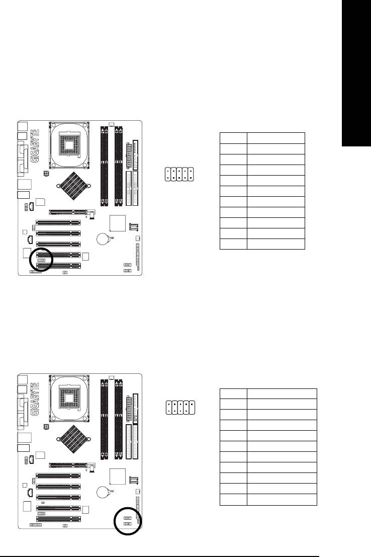
17) IR_CIR
To enable the IR/CIR function on the board, you are required to purchase an option IR/CIR module. To
use IR function only, please connect IR module to Pin1 to Pin5. Be careful with the polarity of the IR/
CIR connector. Check the pin assignment carefully while you connect the IR/CIR cable, incorrect
connection between the cable and connector will make the device unable to work or even damage it.
For optional IR/CIR cable, please contact your local dealer.
Pin No. Definition
1 VCC
2NC
6
10
3 IRRX
1
5
4 GND
5IRTX
6NC
7 CIRRX
8 +5VSB
9 CIRTX
10 NC
18) F_ USB1 / F_USB2 (Front USB Connector)
Be careful with the polarity of the front USB connector. Check the pin assignment carefully while you
connect the front USB cable, incorrect connection between the cable and connector will make the
device unable to work or even damage it. For optional front USB cable, please contact your local
dealer.
Pin No. Definition
2
10
1 Power
2 Power
1
9
3 USB0 DX-/USB6 DX-
4 USB1 Dy-/USB7 Dy-
5 USB0 DX+/USB6 DX+
6 USB1 Dy+/USB7 Dy+
7 GND
8 GND
9 No Pin
10 NC
- 27 - Hardware Installation Process
19) GAME (GAME Connector)
This connector supports joystick, MIDI keyboard and other relate audio devices.
Pin No. Definition
English
1 VCC
2 GRX1_R
2
16
3 GND
4 GPSA2
1
15
5 VCC
6 GPX2_R
7 GPY2_R
8 MSI_R
9 GPSA1
10 GND
11 GPY1_R
12 VCC
13 GPSB1
14 MSO_R
15 GPSB2
16 No Pin
20) INFO_LINK
This connector allows you to connect some external devices to provide you extra function. Check the
pin assignment while you connect the external device cable. Please contact your nearest dealer for
optional external device cable.
Pin No. Definition
10
9
1 SMBCLK
2 VCC
3 SMBDATA
4 GPIO
2
1
5 GND
6 GND
7 No Pin
8NC
9 +12V
10 +12V
- 28 -GA-8I865PE-TW Motherboard
English
21) CI (Chassis Intrusion, Case Open)
This 2-pin connector allows your system to enable or disable the "case open" item in BIOS if the
system case begin remove.
Pin No. Definition
1
1 Signal
2 GND
22) CLR_CMOS (Clear CMOS)
You may clear the CMOS data to its default values by this jumper. To clear CMOS, temporarily short
1-2 pin. Default doesn't include the "Shunter" to prevent from improper use this jumper.
1
Open: Normal
1
Close: Clear CMOS
- 29 - Hardware Installation Process

English
- 30 -GA-8I865PE-TW Motherboard


