Gigabyte GA-8I845G: Chapter 2 BIOS Setup
Chapter 2 BIOS Setup: Gigabyte GA-8I845G

English
Chapter 2 BIOS Setup
BIOS (Basic Input and Output System) includes a CMOS SETUP utility which allows user to configure
required settings or to activate certain system features.
The CMOS SETUP saves the configuration in the CMOS SRAM of the motherboard.
When the power is turned off, the battery on the motherboard supplies the necessary power to the CMOS
SRAM.
When the power is turned on, pushing the <Del> button during the BIOS POST (Power-On Self Test) will
take you to the CMOS SETUP screen. You can enter the BIOS setup screen by pressing "Ctrl + F1".
When setting up BIOS for the first time, it is recommended that you save the current BIOS to a disk in the
event that BIOS needs to be reset to its original settings. If you wish to upgrade to a new BIOS, either
Gigabyte's Q-Flash or @BIOS utility can be used.
Q-Flash allows the user to quickly and easily update or backup BIOS without entering the operating system.
@BIOS is a Windows-based utility that does not require users to boot to DOS before upgrading BIOS but
directly download and update BIOS from the Internet.
CONTROL KEYS
< >< >< >< > Move to select item
<Enter> Select Item
<Esc> Main Menu - Quit and not save changes into CMOS Status Page Setup Menu
and Option Page Setup Menu - Exit current page and return to Main Menu
<Page Up> Increase the numeric value or make changes
<Page Down> Decrease the numeric value or make changes
<F1> General help, only for Status Page Setup Menu and Option Page Setup Menu
<F2> Item Help
<F5> Restore the previous CMOS value from CMOS, only for Option Page Setup Menu
<F6> Load the file-safe default CMOS value from BIOS default table
<F7> Load the Optimized Defaults
<F8> Q-Flash utility
<F9> System Information
<F10> Save all the CMOS changes, only for Main Menu
Main Menu
The on-line description of the highlighted setup function is displayed at the bottom of the screen.
Status Page Setup Menu / Option Page Setup Menu
Press F1 to pop up a small help window that describes the appropriate keys to use and the possible selec-
tions for the highlighted item. To exit the Help Window press <Esc>.
BIOS Setup- 27 -
The BIOS Setup menus described in this chapter are for reference only and may differ from the
exact settings for your motherboard.
English
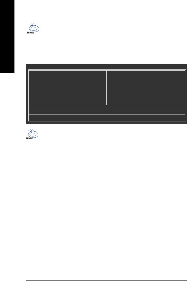
The Main Menu (Example BIOS Version: F1a)
Once you enter Award BIOS CMOS Setup Utility, the Main Menu (as figure below) will appear on the
screen. Use arrow keys to select among the items and press <Enter> to accept or enter the sub-menu.
CMOS Setup Utility-Copyright (C) 1984-2005 A ward Software
` Standard CMOS Features
Top Performance
` Advanced BIOS Features
Load Fail-Safe Defaults
` Integrated Peripherals
Load Optimized Defaults
` Power Management Setup
Set Supervisor Password
` PnP/PCI Configurations
Set User Password
` PC Health Status
Save & Exit Setup
` Frequency/Voltage Control
Exit Without Saving
Esc: Quit KLJI: Select Item
F8: Q-Flash F10: Save & Exit Setup
T ime, Date, Hard Disk T ype...
If you can't find the setting you want, please press "Ctrl+F1" to access hidden advanced
options.
Standard CMOS Features
This setup page includes all the items in standard compatible BIOS.
Advanced BIOS Features
This setup page includes all the items of Award special enhanced features.
Integrated Peripherals
This setup page includes all onboard peripherals.
Power Management Setup
This setup page includes all the items of Green function features.
PnP/PCI Configuration
This setup page includes all the configurations of PCI & PnP ISA resources.
PC Health Status
This setup page includes information about the system autodetected temperature, voltage, fan,
speed.
Frequency/Voltage Control
This setup page is to control CPU clock and frequency ratio.
Top Performance
If you wish to maximize the performance of your system, enable Top Performance.
GA-8I845G(-C) Motherboard - 28 -

English
Load Fail-Safe Defaults
Fail-Safe Defaults indicate the value of the system parameters with which the system would be
in safe configuration.
Load Optimized Defaults
Optimized Defaults indicate the value of the system parameters with which the system would be
in best performance configuration.
Set Supervisor Password
Change, set, or disable password. It allows you to limit access to the system and Setup, or just to Setup.
Set User Password
Change, set, or disable password. It allows you to limit access to the system.
Save & Exit Setup
Save CMOS value settings to CMOS and exit setup.
Exit Without Saving
Abandon all CMOS value changes and exit setup.
BIOS Setup- 29 -

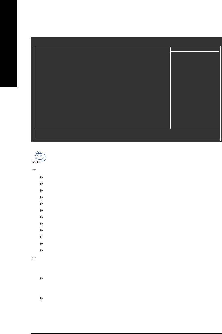
2-1 Standard CMOS Features
CMOS Setup Utility-Copyright (C) 1984-2005 A ward Software
Standard CMOS Features
Date (mm:dd:yy) Fri, Jun 3 2005
Item Help
English
Time (hh:mm:ss) 22:31:24
Menu Level `
` IDE Primary Master [None]
Change the day, month,
` IDE Primary Slave [None]
year
` IDE Secondary Master [None]
` IDE Secondary Slave [None]
< Week>
Sun. to Sat.
Drive A [1.44M, 3.5"]
Drive B [None]
<Month>
Floppy 3 Mode Support [Disabled]
Jan. to Dec.
Halt On [All, But Keyboard]
<Day>
1 to 31 (or maximum
Base Memory 640K
allowed in the month)
Extended Memory 127M
Total Memory 128M
< Y ear>
1999 to 2098
KLJI: Move Enter: Select +/-/PU/PD: V alue F10: Save ESC: Exit F1: General Help
F5: Previous V alues F6: Fail-Safe Defaults F7: Optimized Defaults
Date
The date format is <week>, <month>, <day>, <year>.
Week The week, from Sun to Sat, determined by the BIOS and is displayed only.
Month The month, Jan. through Dec.
Day The day, from 1 to 31 (or the maximum allowed in the month).
Year The year, from 1999 through 2098.
Time
The times format in <hour> <minute> <second>. The time is calculated based on the 24-hour
military-time clock. For example, 1 p.m. is 13:00:00.
IDE Primary Master, Slave /IDE Secondary Master, Slave
IDE HDD Auto-Detection Press "Enter" to select this option for automatic device detection.
IDE Primary/Secondary Master(Slave) setup You can use one of the three methods below:
Auto Allows BIOS to automatically detect IDE devices during POST(default)
None Select this if no IDE devices are used and the system will skip the automatic
detection step and allow for faster system start up.
Manual User can manually input the correct settings
Access Mode Use this to set the access mode for the hard drive. The four options are:
CHS/LBA/Large/Auto (Default:Auto)
Capacity Capacity of currently installed hard disk.
Hard drive information should be labeled on the outside drive casing.
Enter the appropriate option based on this information.
Cylinder Number of cylinders
Head Number of heads
Precomp Write precomp
Landing Zone Landing zone
Sector Number of sectors
GA-8I845G(-C) Motherboard - 30 -

English
Drive A / Drive B
The category identifies the types of floppy disk drive A or drive B that has been installed in
the computer.
None No floppy drive installed
360K, 5.25" 5.25 inch PC-type standard drive; 360K byte capacity.
1.2M, 5.25" 5.25 inch AT-type high-density drive; 1.2M byte capacity
(3.5 inch when 3 Mode is Enabled).
720K, 3.5" 3.5 inch double-sided drive; 720K byte capacity
1.44M, 3.5" 3.5 inch double-sided drive; 1.44M byte capacity. (Default value)
2.88M, 3.5" 3.5 inch double-sided drive; 2.88M byte capacity.
Floppy 3 Mode Support (for Japan Area)
Disabled Normal Floppy Drive. (Default value)
Drive A Drive A is 3 mode Floppy Drive.
Drive B Drive B is 3 mode Floppy Drive.
Both Drive A & B are 3 mode Floppy Drives.
Halt on
The category determines whether the computer will stop if an error is detected during power up.
No Errors The system boot will not stop for any error that may be detected and you
will be prompted.
All Errors Whenever the BIOS detects a non-fatal error the system will be stopped.
All, But Keyboard The system boot will not stop for a keyboard error; it will stop for all other
errors. (Default value)
All, But Diskette The system boot will not stop for a disk error; it will stop for all other errors.
All, But Disk/Key The system boot will not stop for a keyboard or disk error; it will stop for all
other errors.
Memory
The category is display-only and is determined by POST (Power On Self Test) of the BIOS.
Base Memory
The POST of the BIOS will determine the amount of base (or conventional) memory installed
in the system.
The value of the base memory is typically 512K for systems with 512K memory installed on
the motherboard, or 640K for systems with 640K or more memory installed on the motherboard.
Extended Memory
The BIOS determines how much extended memory is present during the POST.
This is the amount of memory located above 1 MB in the CPU's memory address map.
Total Memory
This item displays the memory size that used.
BIOS Setup- 31 -
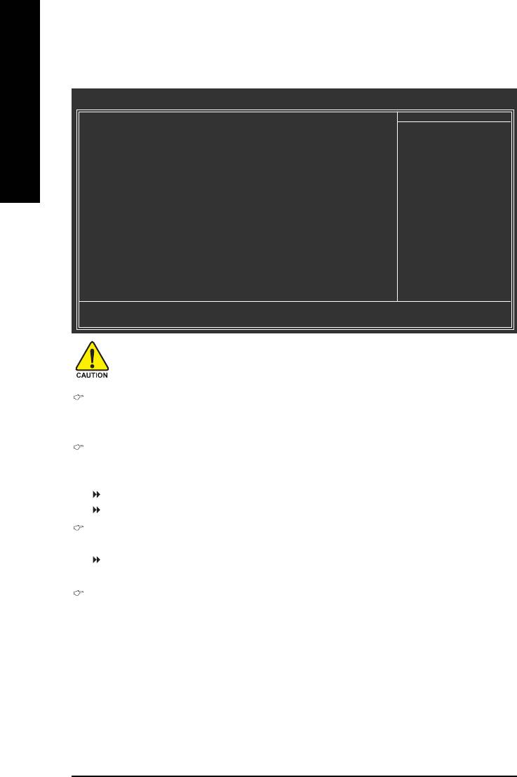
2-2 Advanced BIOS Features
CMOS Setup Utility-Copyright (C) 1984-2005 A ward Software
Advanced BIOS Features
` First Boot Device [Floppy]
Item Help
English
Second Boot Device [HDD-0]
Menu Level `
Third Boot Device [CDROM]
Boot Up Floppy Seek [Disabled]
Select Boot Device
Password Check [Setup]
Priority
#
CPU Hyper-Threading
[Enabled]
Init Display First [Onboard/AGP]
[Floppy]
Graphics Aperture Size [128MB]
Boot from floppy
Graphics Share Memory [8MB]
[LS120]
Boot from LS120
[HDD-0]
Boot from First HDD
[HDD-1]
Boot from second HDD
KLJI: Move Enter: Select +/-/PU/PD: V alue F10: Save ESC: Exit F1: General Help
F5: Previous V alues F6: Fail-Safe Defaults F7: Optimized Defaults
®
"#" This option is available only when the processor you install supports Intel
Hyper-
Threading Technology.
First / Second / Third Boot Device
Floppy Select your boot device priority by Floppy.
LS120 Select your boot device priority by LS120.
HDD-0~3 Select your boot device priority by Hard Disk.
SCSI Select your boot device priority by SCSI.
CDROM Select your boot device priority by CDROM.
ZIP Select your boot device priority by ZIP.
USB-FDD Select your boot device priority by USB-FDD.
USB-ZIP Select your boot device priority by USB-ZIP.
USB-CDROM Select your boot device priority by USB-CDROM.
USB-HDD Select your boot device priority by USB-HDD.
LAN Select your boot device priority by LAN.
Disabled Select your boot device priority by Disabled.
Boot Up Floppy Seek
During POST, BIOS will determine the floppy disk drive installed is 40 or 80 tracks. 360K
type is 40 tracks 720K, 1.2M and 1.44M are all 80 tracks.
Disabled BIOS will not search for the type of floppy disk drive by track number. Note
that there will not be any warning message if the drive installed is 360K.
(Default value)
Enabled BIOS searches for floppy disk drive to determine if it is 40 or 80 tracks. Note
that BIOS can not tell from 720K, 1.2M or 1.44M drive type as they are all 80
tracks
GA-8I845G(-C) Motherboard - 32 -

English
Password Check
Setup The system will boot but will not access to Setup page if the correct
password is not entered at the prompt. (Default value)
System The system will not boot and will not access to Setup page if the correct
password is not entered at the prompt.
If you want to cancel the setting of password, please just press ENTER to make [SETUP] empty.
CPU Hyper-Threading
®
This option appears only when the processor you install supports Intel
Hyper-Threading Technology.
Enabled Enable CPU Hyper-Threading feature. Please note that this feature is only
working for operating system with multiprocessors mode supported.
(Default value)
Disabled Disable CPU Hyper-Threading.
Init Display First
Select the first initiation of the monitor display from onboard/AGP or PCI VGA card.
PCI Set Init Display First to PCI VGA card.
Onboard/AGP Set Init Display First to onboard/AGP VGA card.(Default value)
Graphics Aperture Size
This option is available only when you use the onboard VGA function.
128MB Set Graphics Aperture Size to 128MB. (Default value)
Disabled Disable this function.
Graphics Share Memory
This option is available only when you use the onboard VGA function.
8MB Set Graphics Share Memory to 8MB. (Default value)
1MB Set Graphics Share Memory to 1MB.
BIOS Setup- 33 -

2-3 Integrated Peripherals
CMOS Setup Utility-Copyright (C) 1984-2005 A ward Software
Integrated Peripherals
On-Chip Primary PCI IDE [Enabled]
Item Help
English
On-Chip Secondary PCI IDE [Enabled]
Menu Level `
IDE1 Conductor Cable [Auto]
IDE2 Conductor Cable [Auto]
If a hard disk
USB Controller [Enabled]
controller card is
USB Keyboard Support [Disabled]
used, set at Disabled
USB Mouse Support [Disabled]
AC97 Audio [Auto]
[Enabled]
(
)
Onboard H/W LAN
*
[Enabled]
Enable onboard IDE
Onboard Serial Port 1 [3F8/IRQ4]
PORT
Onboard Serial Port 2 [2F8/IRQ3]
Onboard Parallel Port [378/IRQ7]
[Disabled]
Parallel Port Mode [SPP]
Disable onboard IDE
x ECP Mode Use DMA 3
PORT
Game Port Address [201]
Midi Port Address [Disabled]
x Midi Port IRQ 10
KLJI: Move Enter: Select +/-/PU/PD: V alue F10: Save ESC: Exit F1: General Help
F5: Previous V alues F6: Fail-Safe Defaults F7: Optimized Defaults
On-Chip Primary PCI IDE
Enabled Enable onboard 1st channel IDE port. (Default value)
Disabled Disable onboard 1st channel IDE port.
On-Chip Secondary PCI IDE
Enabled Enable onboard 2nd channel IDE port. (Default value)
Disabled Disable onboard 2nd channel IDE port.
IDE1 Conductor Cable
Auto BIOS autodetects IDE1 conductor cable .(Default Value)
ATA66/100 Set IDE1 Conductor Cable to ATA66/100 (please make sure your IDE
device and cable are compatible with ATA66/100).
ATA33 Set IDE1 Conductor Cable to ATA33. (Please make sure your IDE
device and cable are compatible with ATA33)
IDE2 Conductor Cable
Auto BIOS autodetects IDE2 conductor cable. (Default Value)
ATA66/100 Set IDE2 Conductor Cable to ATA66/100(please make sure your IDE
device and cable are compatible with ATA66/100)
ATA33 Set IDE2 Conductor Cable to ATA33. (Please make sure your IDE
device and cable are compatible with ATA33)
USB Controller
Enabled Enable USB Controller. (Default value)
Disabled Disable USB Controller.
USB Keyboard Support
Enabled Enable USB Keyboard Support.
Disabled Disable USB Keyboard Support. (Default value)
(
)
*
Only for GA-8I845G.
GA-8I845G(-C) Motherboard - 34 -

English
USB Mouse Support
Enabled Enable USB Mouse Support.
Disabled Disable USB Mouse Support. (Default value)
AC97 Audio
Auto Auto detect AC97 audio function. (Default value)
Disabled Disable AC97 audio function.
(
)
Onboard H/W LAN
*
Enabled Enable Onboard H/W LAN function. (Default value)
Disabled Disable this function.
Onboard Serial Port 1
Auto BIOS will automatically setup the Serial port 1 address.
3F8/IRQ4 Enable onboard Serial port 1 and address is 3F8/IRQ4. (Default value)
2F8/IRQ3 Enable onboard Serial port 1 and address is 2F8/IRQ3.
3E8/IRQ4 Enable onboard Serial port 1 and address is 3E8/IRQ4.
2E8/IRQ3 Enable onboard Serial port 1 and address is 2E8/IRQ3.
Disabled Disable onboard Serial port 1.
Onboard Serial Port 2
Auto BIOS will automatically setup the Serial port 2 address.
3F8/IRQ4 Enable onboard Serial port 2 and address is 3F8/IRQ4.
2F8/IRQ3 Enable onboard Serial port 2 and address is 2F8/IRQ3. (Default value)
3E8/IRQ4 Enable onboard Serial port 2 and address is 3E8/IRQ4.
2E8/IRQ3 Enable onboard Serial port 2 and address is 2E8/IRQ3.
Disabled Disable onboard Serial port 2.
Onboard Parallel Port
Disabled Disable onboard LPT port.
378/IRQ7 Enable onboard LPT port and address is 378/IRQ7. (Default value)
278/IRQ5 Enable onboard LPT port and address is 278/IRQ5.
3BC/IRQ7 Enable onboard LPT port and address is 3BC/IRQ7.
Parallel Port Mode
SPP Use Parallel port as Standard Parallel Port. (Default value)
EPP Use Parallel port as Enhanced Parallel Port.
ECP Use Parallel port as Extended Capabilities Port.
ECP+EPP Use Parallel port as ECP & EPP mode.
ECP Mode Use DMA
This option is available only when Parallel Port Mode is set to ECP or ECP+EPP.
3 Set ECP Mode Use DMA to 3. (Default value)
1 Set ECP Mode Use DMA to 1.
Game Port Address
Disabled Disable this function
201 Enable this function and set gameport address to 201. (Default value)
209 Enable this function and set gameport address to 209.
(
)
*
Only for GA-8I845G.
BIOS Setup- 35 -

Midi Port Address
Disabled Disable this function. (Default value)
330 Enable this function and set midiport address to 330.
300 Enable this function and set midiport address to 300.
English
Midi Port IRQ
This option is available when the Midi Port Address is not set to "Disabled."
5 Set midiport IRQ to 5.
10 Set midiport IRQ to 10. (Default value)
2-4 Power Management Setup
CMOS Setup Utility-Copyright (C) 1984-2005 A ward Software
Power Management Setup
ACPI Suspend Type [S1(POS)]
Item Help
Power LED in S1 state [Blinking]
Menu Level `
Soft-Off by PWR-BTTN [Instant-Off]
PME Event W ake Up [Enabled]
[S1]
ModemRingOn [Enabled]
Set suspend type to
Resume by Alarm [Disabled]
Power On Suspend under
x Date (of Month) Alarm Everyday
ACPI OS
x Time (hh:mm:ss) Alarm 0 : 0 : 0
Power On By Mouse [Disabled]
[S3]
Power On By Keyboard [Disabled]
Set suspend type to
x KB Power ON Password Enter
Suspend to RAM under
AC BACK Function [Soft-Off]
ACPI OS
KLJI: Move Enter: Select +/-/PU/PD: V alue F10: Save ESC: Exit F1: General Help
F5: Previous V alues F6: Fail-Safe Defaults F7: Optimized Defaults
ACPI Suspend Type
S1(POS) Set ACPI suspend type to S1/POS(Power On Suspend). (Default value)
S3(STR) Set ACPI suspend type to S3/STR(Suspend To RAM).
Power LED in S1 State
Blinking The Power LED will be blinking during S1 state. (Default value)
Dual/Off The Power LED will be turned off or change color.
Soft-Off by PWR-BTTN
Instant-off Press power button then Power off instantly. (Default value)
Delay 4 Sec. Press power button 4 sec. to Power off. Enter suspend if button is pressed
less than 4 sec.
PME Event Wake Up
Disabled Disable this function.
Enabled Enable PME Event Wake up. (Default value)
GA-8I845G(-C) Motherboard - 36 -

English
ModemRingOn
Disabled Disable the ModemRingOn function.
Enabled Enable the ModemRingOn function. (Default value)
Resume by Alarm
You can set "Resume by Alarm" item to enabled and key in date/time to power on system.
Disabled Disable this function. (Default value)
Enabled Enable alarm function to turn on system.
If Resume by Alarm is Enabled:
Date (of Month) Alarm : Everyday, 1~31
Time (hh: mm: ss) Alarm : (0~23) : (0~59) : (0~59)
Power On By Mouse
Disabled Disable this function. (Default value)
Double Click Double-click PS/2 mouse left button to power on the system.
Power On By Keyboard
Password Enter from 1 to 5 characters to set the Keyboard Power On Password.
Disabled Disabled this function. (Default value)
Keyboard 98 If your keyboard have "POWER Key" button, you can press the key to
power on the system.
KB Power ON Password
When "Power On by Keyboard" is set at Password, you can set the password here.
Enter Input password (from 1 to 5 characters) and press Enter to set the Keyboard
Power On password.
AC BACK Function
Soft-Off When AC-power comes back to the system, the system will be in the off
state. (Default value)
Full-On When AC-power comes back to the system, the system always stay in the
on state.
Memory When AC-power comes back to the system, the system will return to the
last state before AC-power off.
BIOS Setup- 37 -

2-5 PnP/PCI Configurations
CMOS Setup Utility-Copyright (C) 1984-2005 A ward Software
PnP/PCI Configurations
English
PCI1/5 IRQ Assignment [Auto]
Item Help
PCI2 IRQ Assignment [Auto]
Menu Level `
PCI3 IRQ Assignment [Auto]
PCI4 IRQ Assignment [Auto]
Device(s) using this
INT:
USB1.1 Host Cntrlr
-Bus 0 Dev29 Func 2
KLJI: Move Enter: Select +/-/PU/PD: V alue F10: Save ESC: Exit F1: General Help
F5: Previous V alues F6: Fail-Safe Defaults F7: Optimized Defaults
PCI1/5 IRQ Assignment
Auto Auto assign IRQ to PCI 1/5. (Default value)
3,4,5,7,9,10,11,12,14,15 Set IRQ 3,4,5,7,9,10,11,12,14,15 to PCI 1/5.
PCI2 IRQ Assignment
Auto Auto assign IRQ to PCI 2. (Default value)
3,4,5,7,9,10,11,12,14,15 Set IRQ 3,4,5,7,9,10,11,12,14,15 to PCI 2.
PCI3 IRQ Assignment
Auto Auto assign IRQ to PCI 3. (Default value)
3,4,5,7,9,10,11,12,14,15 Set IRQ 3,4,5,7,9,10,11,12,14,15 to PCI 3.
PCI4 IRQ Assignment
Auto Auto assign IRQ to PCI 4. (Default value)
3,4,5,7,9,10,11,12,14,15 Set IRQ 3,4,5,7,9,10,11,12,14,15 to PCI 4.
GA-8I845G(-C) Motherboard - 38 -

English
2-6 PC Health Status
CMOS Setup Utility-Copyright (C) 1984-2005 A ward Software
PC Health Status
Reset Case Open Status [Disabled]
Item Help
Case Opened Y es
Menu Level `
Vcore O K
DDR25V O K
[Disabled]
+3.3V O K
Don’t reset case
+12V O K
open status
o
Current CPU Temperature 33
C
Current CPU FAN Speed 4687 RPM
[Enabled]
Current SYSTEM FAN Speed 0 RPM
Clear case open status
CPU W arning T emperature [Disabled]
and set to be Disabled
CPU FAN Fail W arning [Disabled]
at next boot
SYSTEM FAN Fail W arning [Disabled]
KLJI: Move Enter: Select +/-/PU/PD: V alue F10: Save ESC: Exit F1: General Help
F5: Previous V alues F6: Fail-Safe Defaults F7: Optimized Defaults
Reset Case Open Status
Disabled Don't reset the Case Open status. (Default value)
Eabled Clear the Case Open status at next boot.
Case Opened
If the case is closed, Case Opened will show "No."
If the case has been opened, Case Opened will show "Yes".
If you want to reset the Case Opened value, enable Reset Case Open Status and save to
CMOS, and your computer will restart.
Current Voltage(V) Vcore / DDR25V / +3.3V / +12V
Detect system's voltage status automatically.
Current CPU Temperature
Detect CPU temperature automatically.
Current CPU/SYSTEM FAN Speed (RPM)
Detect CPU/system fan speed status automatically.
CPU Warning Temperature
o
o
o
o
60
C / 140
F Monitor CPU temperature at 60
C / 140
F.
o
o
o
o
70
C / 158
F Monitor CPU temperature at 70
C / 158
F.
o
o
o
o
80
C / 176
F Monitor CPU temperature at 80
C / 176
F.
o
o
o
o
90
C / 194
F Monitor CPU temperature at 90
C / 194
F.
Disabled Disable this function. (Default value)
CPU/SYSTEM FAN Fail Warning
Disabled Disable fan fail warning function . (Default value)
Enabled Enable fan fail warning function.
BIOS Setup- 39 -
2-7 Frequency/Voltage Control
CMOS Setup Utility-Copyright (C) 1984-2005 A ward Software
Frequency/Voltage Control
CPU Clock Ratio [15X]
Item Help
English
CPU Host Clock Control [Disabled]
Menu Level `
x CPU Host Frequency (Mhz) 100
x Fixed PCI/AGP Frequency 33/66
Set CPU Ratio if CPU
Host/DRAM Clock ratio Auto
Ratio is unclocked
Memory Frequency (Mhz) 266
PCI/AGP Frequency (Mhz) 33/66
KLJI: Move Enter: Select +/-/PU/PD: V alue F10: Save ESC: Exit F1: General Help
F5: Previous V alues F6: Fail-Safe Defaults F7: Optimized Defaults
Incorrect using these features may cause your system broken. For power end-user use only.
CPU Clock Ratio
This setup option will be automatically assigned by CPU detection.
The option will display "Locked" and read only if the CPU ratio is not changeable.
CPU Host Clock Control
Please note that if your system is overclocked and cannot restart, please wait 20 secs.
for automatic system restart or clear the CMOS setup data and perform a safe restart.
Disabled Disable CPU Host Clock Control. (Default value)
Enabled Enable CPU Host Clock Control.
CPU Host Frequency (Mhz)
This item will be available when "CPU Host Clock Control" is set to Enabled.
100MHz ~ 355MHz Set CPU Host Clock from 100MHz to 355MHz.
Inappropriate using it may cause your system corrupted. For power End-User use only!
Fixed PCI/AGP Frequency
You can choose those modes to adjust PCI/AGP frequency. (Select PCI/AGP frequency
asynchronous with CPU frequency).
GA-8I845G(-C) Motherboard - 40 -

English
Host/DRAM Clock ratio
For FSB (Front Side Bus) frequency=400MHz,
2.0 Memory Frequency = Host clock X 2.0.
2.66 Memory Frequency = Host clock X 2.66.
Auto Set Memory frequency by DRAM SPD data. (Default value)
For FSB (Front Side Bus) frequency=533MHz,
2.0 Memory Frequency = Host clock X 2.0.
2.5 Memory Frequency = Host clock X 2.5.
Auto Set Memory frequency by DRAM SPD data. (Default value)
Memory Frequency (Mhz)
The values depend on CPU Host Frequency (Mhz) and Host/DRAM Clock ratio setting.
PCI/AGP Frequency (Mhz)
The values depend on Fixed PCI/AGP Frequency.
2-8 Top Performance
CMOS Setup Utility-Copyright (C) 1984-2005 A ward Software
` Standard CMOS Features
Top Performance
` Advanced BIOS Features
Load Fail-Safe Defaults
Top Performance
` Integrated Peripherals
Load Optimized Defaults
` Power Management Setup
Disabled.........................[]
Set Supervisor Password
` PnP/PCI Configurations
Enabled..........................[ ]
Set User Password
` PC Health Status
Save & Exit Setup
` Frequency/Voltage Control
Exit Without Saving
Esc: Quit KLJI: Select Item
KL: Move ENTER: Accept
F8: Q-Flash F10: Save & Exit Setup
ESC: Abort
System will be set in best performance configuration..
If you wish to maximize the performance of your system, enable "Top Performance."
Disabled Disable this function. (Default Value)
Enabled Enable Top Performance function.
"Top Performance" will increase H/W working speed. Different system configuration (both H/W
component and OS) will effect the result. For example, the same H/W configuration might not run
properly with Windows XP, but works smoothly with Windows NT. Therefore, if your system is not
perform enough, the reliability or stability problem will appear sometimes, and we will recommend you
disabling the option to avoid the problem as mentioned above.
BIOS Setup- 41 -

2-9 Load Fail-Safe Defaults
CMOS Setup Utility-Copyright (C) 1984-2005 A ward Software
` Standard CMOS Features
Top Performance
English
` Advanced BIOS Features
Load Fail-Safe Defaults
` Integrated Peripherals
Load Optimized Defaults
` Power Management Setup
Set Supervisor Password
` PnP/PCI Configurations
Load Fail-Safe Defaults (Y/N)? N
Set User Password
` PC Health Status
Save & Exit Setup
` Frequency/Voltage Control
Exit Without Saving
Esc: Quit KLJI: Select Item
F8: Q-Flash F10: Save & Exit Setup
Load Fail-Safe Defaults
Fail-Safe defaults contain the most appropriate values of the system parameters that allow minimum system
performance.
2-10 Load Optimized Defaults
CMOS Setup Utility-Copyright (C) 1984-2005 A ward Software
` Standard CMOS Features
Top Performance
` Advanced BIOS Features
Load Fail-Safe Defaults
` Integrated Peripherals
Load Optimized Defaults
` Power Management Setup
Set Supervisor Password
` PnP/PCI Configurations
Load Optimized Defaults (Y/N)? N
Set User Password
` PC Health Status
Save & Exit Setup
` Frequency/Voltage Control
Exit Without Saving
Esc: Quit KLJI: Select Item
F8: Q-Flash F10: Save & Exit Setup
Load Optimized Defaults
Selecting this field loads the factory defaults for BIOS and Chipset Features which the system automatically
detects.
GA-8I845G(-C) Motherboard - 42 -

English
2-11 Set Supervisor/User Password
CMOS Setup Utility-Copyright (C) 1984-2005 A ward Software
` Standard CMOS Features
Top Performance
` Advanced BIOS Features
Load Fail-Safe Defaults
` Integrated Peripherals
Load Optimized Defaults
` Power Management Setup
Set Supervisor Password
` PnP/PCI Configurations
Set User Password
` PC Health Status
Enter Password:
Save & Exit Setup
` Frequency/Voltage Control
Exit Without Saving
Esc: Quit KLJI: Select Item
F8: Q-Flash F10: Save & Exit Setup
Change/Set/Disable Password
When you select this function, the following message will appear at the center of the screen to assist
you in creating a password.
Type the password, up to eight characters, and press <Enter>. You will be asked to confirm the password.
Type the password again and press <Enter>. You may also press <Esc> to abort the selection and not enter
a password.
To disable password, just press <Enter> when you are prompted to enter password. A message
"PASSWORD DISABLED" will appear to confirm the password being disabled. Once the password is disabled,
the system will boot and you can enter Setup freely.
The BIOS Setup program allows you to specify two separate passwords:
SUPERVISOR PASSWORD and a USER PASSWORD. When disabled, anyone may access all BIOS Setup
program function. When enabled, the Supervisor password is required for entering the BIOS Setup program
and having full configuration fields, the User password is required to access only basic items.
If you select "System" at "Password Check" in Advance BIOS Features Menu, you will be prompted for the
password every time the system is rebooted or any time you try to enter Setup Menu.
If you select "Setup" at "Password Check" in Advance BIOS Features Menu, you will be prompted only when
you try to enter Setup.
BIOS Setup- 43 -

2-12 Save & Exit Setup
CMOS Setup Utility-Copyright (C) 1984-2005 A ward Software
` Standard CMOS Features
Top Performance
English
` Advanced BIOS Features
Load Fail-Safe Defaults
` Integrated Peripherals
Load Optimized Defaults
` Power Management Setup
Set Supervisor Password
Save to CMOS and EXIT (Y/N)? Y
` PnP/PCI Configurations
Set User Password
` PC Health Status
Save & Exit Setup
` Frequency/Voltage Control
Exit Without Saving
Esc: Quit KLJI: Select Item
F8: Q-Flash F10: Save & Exit Setup
Save Data to CMOS
Type "Y" will quit the Setup Utility and save the user setup value to RTC CMOS.
Type "N" will return to Setup Utility.
2-13 Exit Without Saving
CMOS Setup Utility-Copyright (C) 1984-2005 A ward Software
` Standard CMOS Features
Top Performance
` Advanced BIOS Features
Load Fail-Safe Defaults
` Integrated Peripherals
Load Optimized Defaults
Quit Without Saving (Y/N)? N
` Power Management Setup
Set Supervisor Password
` PnP/PCI Configurations
Set User Password
` PC Health Status
Save & Exit Setup
` Frequency/Voltage Control
Exit Without Saving
Esc: Quit KLJI: Select Item
F8: Q-Flash F10: Save & Exit Setup
Abandon all Data
Type "Y" will quit the Setup Utility without saving to RTC CMOS.
Type "N" will return to Setup Utility.
GA-8I845G(-C) Motherboard - 44 -

English
BIOS Setup- 45 -

English
GA-8I845G(-C) Motherboard - 46 -


