ASRock h61mv-itx: Chapter 2: Installation
Chapter 2: Installation: ASRock h61mv-itx
Chapter 2: Installation
This is a Mini-ITX form factor motherboard. Before you install the motherboard,
study the conguration of your chassis to ensure that the motherboard ts into it.
Make sure to unplug the power cord before installing or removing the
motherboard. Failure to do so may cause physical injuries to you and
damages to motherboard components.
2.1 Screw Holes
Place screws into the holes indicated by circles to secure the motherboard to the
chassis.
Do not over-tighten the screws! Doing so may damage the motherboard.
2.2 Pre-installation Precautions
Take note of the following precautions before you install motherboard components
or change any motherboard settings.
1. Unplug the power cord from the wall socket before touching any component.
2. To avoid damaging the motherboard components due to static electricity,
NEVER place your motherboard directly on the carpet or the like. Also
remember to use a grounded wrist strap or touch a safety grounded object
before you handle components.
3. Hold components by the edges and do not touch the ICs.
4. Whenever you uninstall any component, place it on a grounded antistatic pad or
in the bag that comes with the component.
Before you install or remove any component, ensure that the power is
switched off or the power cord is detached from the power supply.
Failure to do so may cause severe damage to the motherboard, peripherals,
and/or components.
16
2.3 CPU Installation
For the installation of Intel 1155-Pin CPU,
please follow the steps below.
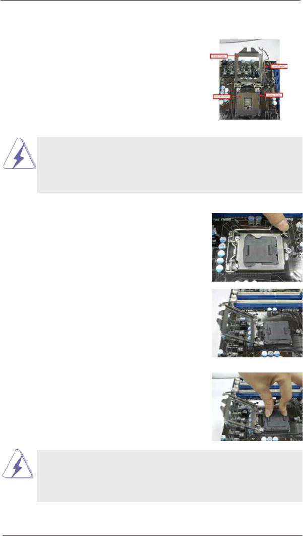
1155-Pin Socket Overview
Before you insert the 1155-Pin CPU into the socket, please check if the
CPU surface is unclean or if there is any bent pin on the socket. Do not
force to insert the CPU into the socket if above situation is found. Other-
wise, the CPU will be seriously damaged.
Step 1. Open the socket:
Step 1-1. Disengaging the lever by depressing
down and out on the hook to clear
retention tab.
Step 1-2. Rotate the load lever to fully open po-
sition at approximately 135 degrees.
Step 1-3. Rotate the load plate to fully open po-
sition at approximately 100 degrees.
Step 2. Remove PnP Cap (Pick and Place Cap).
1. It is recommended to use the cap tab to handle and avoid kicking
off the PnP cap.
2. This cap must be placed if returning the motherboard for after
service.
17
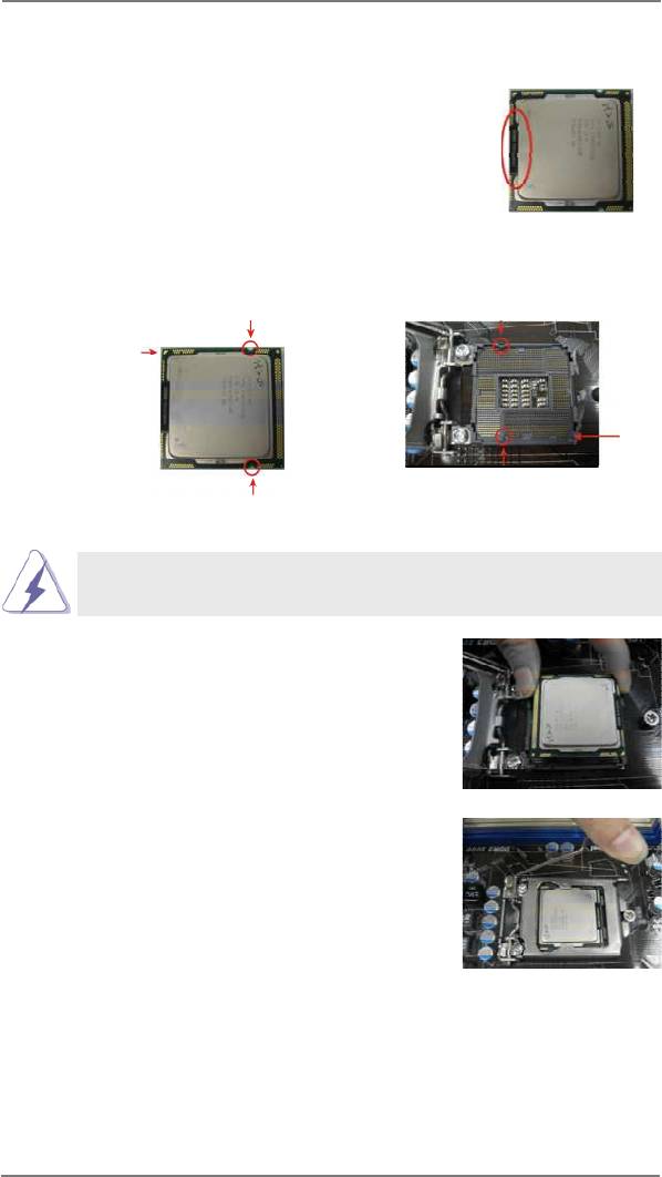
Step 3. Insert the 1155-Pin CPU:
Step 3-1. Hold the CPU by the edge where is
black line
marked with black line.
Step 3-2. Orient the CPU with IHS (Integrated
Heat Sink) up. Locate Pin1 and the
two orientation key notches.
orientation key notch
alignment key
Pin1
Pin1
alignment key
orientation key notch
1155-Pin Socket
1155-Pin CPU
For proper inserting, please ensure to match the two orientation key
notches of the CPU with the two alignment keys of the socket.
Step 3-3. Carefully place the CPU into the
socket by using a purely vertical mo-
tion.
Step 3-4. Verify that the CPU is within the sock-
et and properly mated to the orient
keys.
Step 4. Close the socket:
Step 4-1. Rotate the load plate onto the IHS.
Step 4-2. While pressing down lightly on load
plate, engage the load lever.
18
2.4 Installation of CPU Fan and Heatsink
This motherboard is equipped with 1155-Pin socket that supports Intel 1155-Pin
CPU. Please adopt the type of heatsink and cooling fan compliant with Intel 1155-
Pin CPU to dissipate heat. Before you installed the heatsink, you need to spray
thermal interface material between the CPU and the heatsink to improve heat dis-
sipation. Ensure that the CPU and the heatsink are securely fastened and in good
contact with each other. Then connect the CPU fan to the CPU_FAN connector
(CPU_FAN1, see page 14, No. 18).
For proper installation, please kindly refer to the instruction manuals of your
CPU fan and heatsink.
Below is an example to illustrate the installation of the heatsink for 1155-Pin CPU.
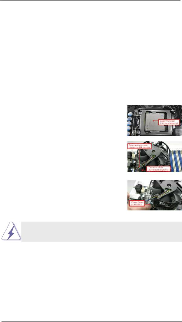
Step 1. Apply thermal interface material onto center of
IHS on the socket surface.
1155-Pin Socket
Step 2. Place the heatsink onto the socket. Ensure
fan cables are oriented on side closest to the
CPU fan connector on the motherboard (CPU_
FAN1, see page 14, No. 18).
Step 3. Align fasteners with the motherboard through-
holes.
Step 4. Rotate the fastener clockwise, then press
down on fastener caps with thumb to install
and lock. Repeat with remaining fasteners.
If you press down the fasteners without rotating them clockwise, the
heatsink cannot be secured on the motherboard.
Step 5. Connect fan header with the CPU fan connector on the motherboard.
Step 6. Secure excess cable with tie-wrap to ensure cable does not interfere with
fan operation or contact other components.
19
2.5 Installation of Memory Modules (DIMM)
This motherboard provides two 240-pin DDR3 (Double Data Rate 3) DIMM slots,
and supports Dual Channel Memory Technology. For dual channel configuration,
you always need to install two identical (the same brand, speed, size and chip-
type) memory modules in the DDR3 DIMM slots to activate Dual Channel Memory
Technology. Otherwise, it will operate at single channel mode.
1. It is not allowed to install a DDR or DDR2 memory module into
DDR3 slot;otherwise, this motherboard and DIMM may be
damaged.
2. If you install only one memory module or two non-identical
memory modules, it is unable to activate the Dual Channel
Memory Technology.
3. Some DDR3 1GB double-sided DIMMs with 16 chips may not
work on this motherboard. It is not recommended to install them
on this motherboard.
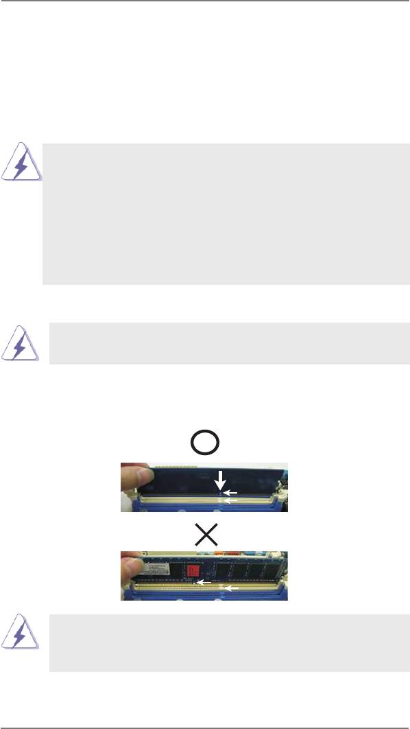
Installing a DIMM
Please make sure to disconnect power supply before adding or
removing DIMMs or the system components.
Step 1. Unlock a DIMM slot by pressing the retaining clips outward.
Step 2. Align a DIMM on the slot such that the notch on the DIMM matches the
break on the slot.
notch
break
notch
break
The DIMM only ts in one correct orientation. It will cause permanent
damage to the motherboard and the DIMM if you force the DIMM into
the slot at incorrect orientation.
Step 3. Firmly insert the DIMM into the slot until the retaining clips at both ends
fully snap back in place and the DIMM is properly seated.
20

2.6 Expansion Slot (PCI Express Slot)
There is 1 PCI Express slot on this motherboard.
PCIE slots:
PCIE1 (PCIE 3.0 x16 slot) is used for PCI Express x16 lane width
graphics cards.
Only PCIE1 slot supports Gen 3 speed. To run the PCI Express in Gen
3 speed, please install an Ivy Bridge CPU. If you install a Sandy Bridge
CPU, the PCI Express will run only at PCI Express Gen 2 speed.
Installing an expansion card
Step 1. Before installing the expansion card, please make sure that the power
supply is switched off or the power cord is unplugged. Please read the
documentation of the expansion card and make necessary hardware
settings for the card before you start the installation.
Step 2. Remove the system unit cover (if your motherboard is already installed
in a chassis).
Step 3. Remove the bracket facing the slot that you intend to use. Keep the
screws for later use.
Step 4. Align the card connector with the slot and press rmly until the card is
completely seated on the slot.
Step 5. Fasten the card to the chassis with screws.
Step 6. Replace the system cover.
21
2.7 Dual Monitor and Surround Display Features
Dual Monitor Feature
This motherboard supports dual monitor feature. With the internal VGA output sup-
port (D-Sub and HDMI), you can easily enjoy the benets of dual monitor feature
without installing any add-on VGA card to this motherboard. This motherboard also
provides independent display controllers for D-Sub and HDMI to support dual VGA
output so that D-sub and HDMI can drive same or different display contents.
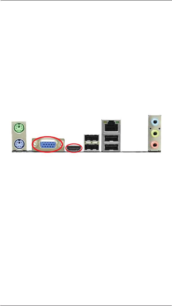
To enable dual monitor feature, please follow the below steps:
1. Connect D-Sub monitor cable to D-Sub port on the I/O panel, or connect HDMI
monitor cable to HDMI port on the I/O panel.
D-Sub port
HDMI port
2. If you have installed onboard VGA driver from our support CD to your system
already, you can freely enjoy the benets of dual monitor function after your
system boots. If you haven’t installed onboard VGA driver yet, please install
onboard VGA driver from our support CD to your system and restart your
computer.
22

Surround Display Feature
This motherboard supports surround display upgrade. With the internal VGA output
support (D-Sub and HDMI) and external add-on PCI Express VGA cards, you can
easily enjoy the benets of surround display feature.
Please refer to the following steps to set up a surround display environment:
1. Install the PCI Express VGA card on PCIE1 slot. Please refer to page 21 for
proper expansion card installation procedures for details.
2. Connect D-Sub monitor cable to D-Sub port on the I/O panel, or connect HDMI
monitor cable to HDMI port on the I/O panel. Then connect other monitor cables
to the corresponding connectors of the add-on PCI Express VGA card on PCIE1
slot.
3. Boot your system. Press <F2> or <Del> to enter UEFI setup. Enter “Share
Memory” option to adjust the memory capability to [32MB], [64MB], [128MB],
[256MB] or [512MB] to enable the function of D-sub. Please make sure that
the value you select is less than the total capability of the system memory. If you
do not adjust the UEFI setup, the default value of “Share Memory”, [Auto], will
disable D-Sub function when the add-on VGA card is inserted to this
motherboard.
4. Install the onboard VGA driver and the add-on PCI Express VGA card driver to
your system. If you have installed the drivers already, there is no need to install
them again.
5. Set up a multi-monitor display.
®
For Windows
XP / XP 64-bit OS:
Right click the desktop, choose “Properties”, and select the “Settings” tab
so that you can adjust the parameters of the multi-monitor according to
the steps below.
A. Click the “Identify” button to display a large number on each monitor.
B. Right-click the display icon in the Display Properties dialog that you
wish to be your primary monitor, and then select “Primary”. When
you use multiple monitors with your card, one monitor will always be
Primary, and all additional monitors will be designated as Secondary.
C. Select the display icon identied by the number 2.
D. Click “Extend my Windows desktop onto this monitor”.
E. Right-click the display icon and select “Attached”, if necessary.
F. Set the “Screen Resolution” and “Color Quality” as appropriate for the
second monitor. Click “Apply” or “OK” to apply these new values.
G. Repeat steps C through E for the diaplay icon identied by the number
one, two, three and four.
23

®
TM
TM
For Windows
8 / 8 64-bit / 7 / 7 64-bit / Vista
/ Vista
64-bit OS:
Right click the desktop, choose “Personalize”, and select the “Display
Settings” tab so that you can adjust the parameters of the multi-monitor
according to the steps below.
A. Click the number ”2” icon.
B. Click the items “This is my main monitor” and “Extend the desktop onto
this monitor”.
C. Click “OK” to save your change.
D. Repeat steps A through C for the display icon identied by the number
three and four.
6. Use Surround Display. Click and drag the display icons to positions representing
the physical setup of your monitors that you would like to use. The placement
of display icons determines how you move items from one monitor to another.
HDCP Function
HDCP function is supported on this motherboard. To use HDCP
function with this motherboard, you need to adopt the monitor
that supports HDCP function as well. Therefore, you can enjoy
the superior display quality with high-denition HDCP
encryption contents. Please refer to below instruction for more
details about HDCP function.
What is HDCP?
HDCP stands for High-Bandwidth Digital Content Protection,
®
a specication developed by Intel
for protecting digital
entertainment content that uses the DVI interface. HDCP is a
copy protection scheme to eliminate the possibility of
intercepting digital data midstream between the video source,
or transmitter - such as a computer, DVD player or set-top box -
and the digital display, or receiver - such as a monitor, television
or projector. In other words, HDCP specication is designed to
protect the integrity of content as it is being transmitted.
Products compatible with the HDCP scheme such as DVD
players, satellite and cable HDTV set-top-boxes, as well as few
entertainment PCs requires a secure connection to a compliant
display. Due to the increase in manufacturers employing HDCP
in their equipment, it is highly recommended that the HDTV or
LCD monitor you purchase is compatible.
24
2.8 ASRock Smart Remote Installation Guide
ASRock Smart Remote is only used for ASRock motherboard with CIR header.
Please refer to below procedures for the quick installation and usage of ASRock
Smart Remote.
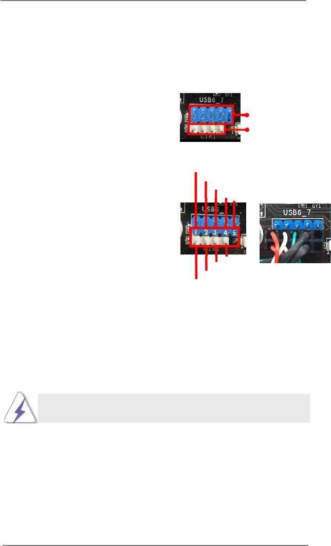
Step1. Find the CIR header located next
to the USB 2.0 header on ASRock
USB 2.0 header (9-pin, blue)
motherboard.
CIR header (4-pin, white)
USB_PWR
P-
Step2. Connect the front USB cable to the
P+
USB 2.0 header (as below, pin 1-5)
GND
DUMMY
and the CIR header. Please make
sure the wire assignments and the
pin assignments are matched
correctly.
GND
IRTX
IRRX
ATX+5VSB
Step3. Install Multi-Angle CIR Receiver to the front USB port.
Step4. Boot up your system. Press <F2> or <Del> to enter BIOS Setup Utility.
Make sure the option "CIR Controller" is setting at [Enabled].
(Advanced -> Super IO Conguration -> CIR Controller -> [Enabled])
If you cannot nd this option, please shut down your system and install
Multi-Angle CIR Receiver to the other front USB port then try again.
Step5. Enter Windows. Execute ASRock support CD and install CIR Driver. (It is
listed at the bottom of driver list.)
25
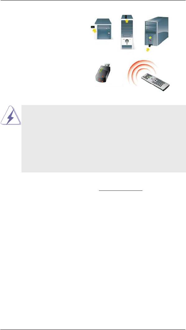
3 CIR sensors in different angles
1. Only one of the front USB port can support CIR function. When
the CIR function is enabled, the other port will remain USB
function.
2. Multi-Angle CIR Receiver is used for front USB only. Please do
not use the rear USB bracket to connect it on the rear panel.
Multi-Angle CIR Receiver can receive the multi-direction infrared
signals (top, down and front), which is compatible with most of
the chassis on the market.
3. The Multi-Angle CIR Receiver does not support Hot-Plug
function. Please install it before you boot the system.
* ASRock Smart Remote is only supported by some of ASRock motherboards. Please refer to
ASRock website for the motherboard support list: http://www.asrock.com
26
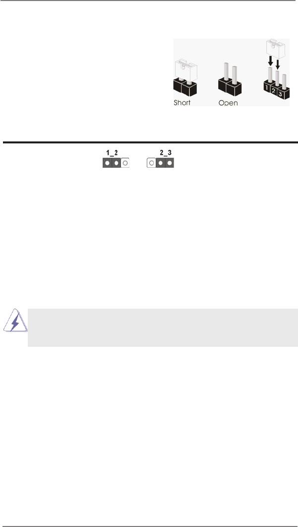
2.9 Jumpers Setup
The illustration shows how jumpers are
setup. When the jumper cap is placed on
pins, the jumper is “Short”. If no jumper cap
is placed on pins, the jumper is “Open”. The
illustration shows a 3-pin jumper whose
pin1 and pin2 are “Short” when jumper cap
is placed on these 2 pins.
Jumper Setting Description
Clear CMOS Jumper
(CLRCMOS1)
(see p.14, No. 1)
Clear CMOSDefault
Note: CLRCMOS1 allows you to clear the data in CMOS. To clear and reset the
system parameters to default setup, please turn off the computer and unplug
the power cord from the power supply. After waiting for 15 seconds, use a
jumper cap to short pin2 and pin3 on CLRCMOS1 for 5 seconds. However,
please do not clear the CMOS right after you update the BIOS. If you need
to clear the CMOS when you just nish updating the BIOS, you must boot up
the system rst, and then shut it down before you do the clear-CMOS action.
Please be noted that the password, date, time and user default prole will be
cleared only if the CMOS battery is removed.
If you clear the CMOS, the case open may be detected. Please adjust
the BIOS option “Clear Status” to clear the record of previous chassis
intrusion status.
27
2.10 Onboard Headers and Connectors
Onboard headers and connectors are NOT jumpers. Do NOT place
jumper caps over these headers and connectors. Placing jumper caps
over the headers and connectors will cause permanent damage of the
motherboard!
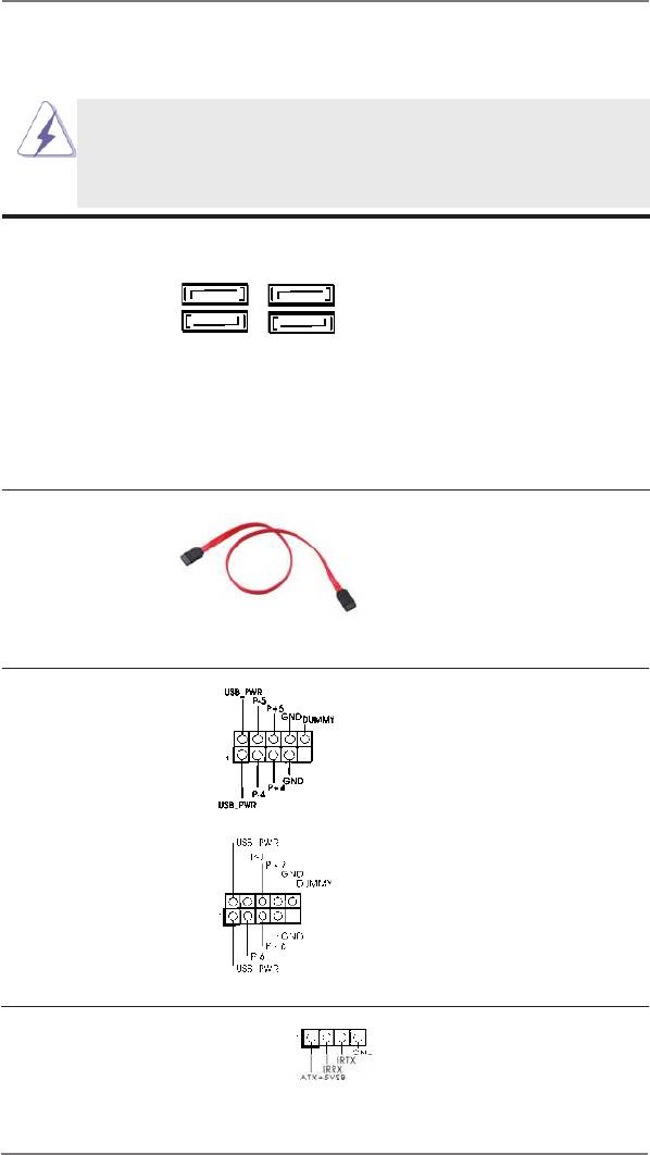
Serial ATA2 Connectors These four Serial ATA2
(SATA_0 (PORT 0):
(SATA2) connectors support
SATA_0 (PORT 0) SATA_2 (PORT 4)
see p.14, No. 4)
SATA data cables for internal
(SATA_1 (PORT 1):
storage devices. The current
see p.14, No. 3)
SATA2 interface allows up to
SATA_1 (PORT 1) SATA_3 (PORT 5)
(SATA_2 (PORT 4):
3.0 Gb/s data transfer rate.
see p.14, No. 5)
(SATA_3 (PORT 5):
see p.14, No. 6)
Serial ATA (SATA) Either end of the SATA data
Data Cable cable can be connected to the
(Optional)
SATA / SATA2 hard disk or the
SATA2 connector on this
motherboard.
USB 2.0 Headers Besides four default USB 2.0
(9-pin USB4_5)
ports on the I/O panel, there
(see p.14 No. 7)
are two USB 2.0 headers on
this motherboard. Each
USB 2.0 header can support
two USB 2.0 ports.
(9-pin USB6_7)
(see p.14 No. 8)
Consumer Infrared Module Header This header can be used to
(4-pin CIR1)
connect the remote
(see p.14 No. 9)
controller receiver.
28
Front Panel Audio Header This is an interface for front
GND
P RESENCE#
(9-pin HD_AUDIO1)
M IC_RET
panel audio cable that allows
OUT_RET
(see p.14 No. 17)
convenient connection and
control of audio devices.
1
O UT2_L
J _SENSE
O UT2_R
M IC2_R
M IC2_L
1. High Denition Audio supports Jack Sensing, but the panel wire on
the chassis must support HDA to function correctly. Please follow the
instruction in our manual and chassis manual to install your system.
2. If you use AC’97 audio panel, please install it to the front panel audio
header as below:
A. Connect Mic_IN (MIC) to MIC2_L.
B. Connect Audio_R (RIN) to OUT2_R and Audio_L (LIN) to OUT2_L.
C. Connect Ground (GND) to Ground (GND).
D. MIC_RET and OUT_RET are for HD audio panel only. You don’t
need to connect them for AC’97 audio panel.
E. To activate the front mic.
®
For Windows
XP / XP 64-bit OS:
Select “Mixer”. Select “Recorder”. Then click “FrontMic”.
®
TM
TM
For Windows
8 / 8 64-bit / 7 / 7 64-bit / Vista
/ Vista
64-bit OS:
Go to the "FrontMic" Tab in the Realtek Control panel. Adjust
“Recording Volume”.
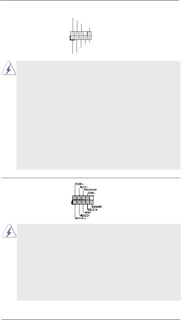
System Panel Header This header accommodates
(9-pin PANEL1)
several system front panel
(see p.14 No. 13)
functions.
Connect the power switch, reset switch and system status indicator on the
chassis to this header according to the pin assignments below. Note the
positive and negative pins before connecting the cables.
PWRBTN (Power Switch):
Connect to the power switch on the chassis front panel. You may congure
the way to turn off your system using the power switch.
RESET (Reset Switch):
Connect to the reset switch on the chassis front panel. Press the reset
switch to restart the computer if the computer freezes and fails to perform a
normal restart.
29
PLED (System Power LED):
Connect to the power status indicator on the chassis front panel. The LED
is on when the system is operating. The LED keeps blinking when the sys-
tem is in S1 sleep state. The LED is off when the system is in S3/S4 sleep
state or powered off (S5).
HDLED (Hard Drive Activity LED):
Connect to the hard drive activity LED on the chassis front panel. The LED
is on when the hard drive is reading or writing data.
The front panel design may differ by chassis. A front panel module mainly
consists of power switch, reset switch, power LED, hard drive activity LED,
speaker and etc. When connecting your chassis front panel module to this
header, make sure the wire assignments and the pin assign-ments are
matched correctly.
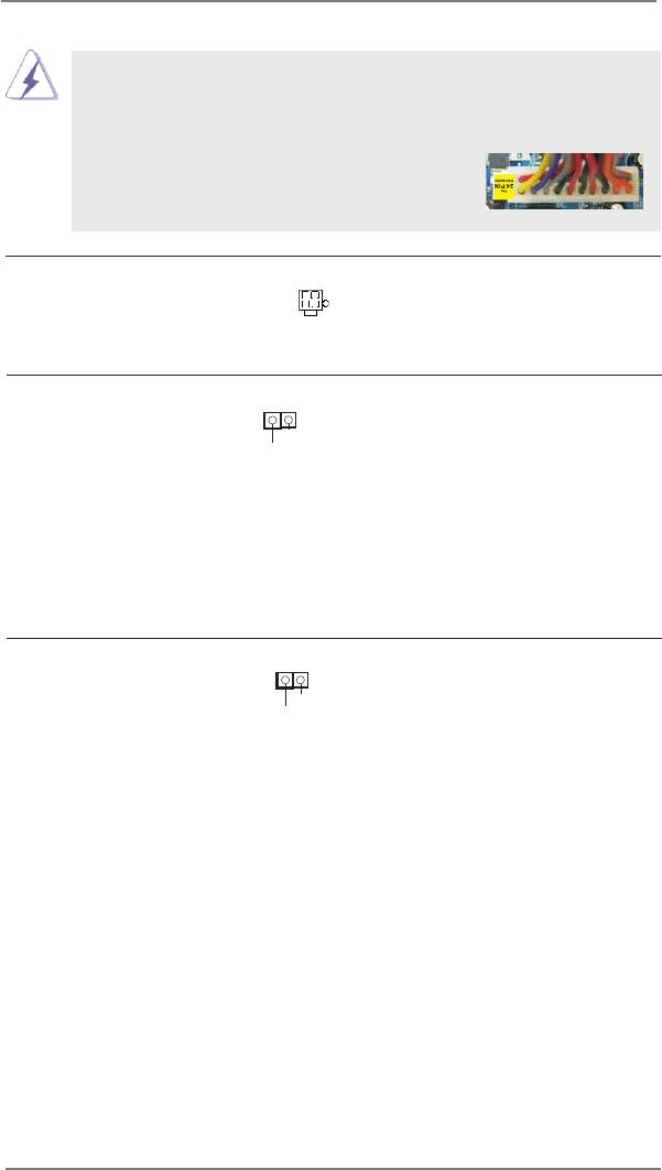
Chassis Fan Connector Please connect the fan cables
(3-pin CHA_FAN1)
to the fan connectors and
(see p.14 No. 2)
match the black wire to the
ground pin.
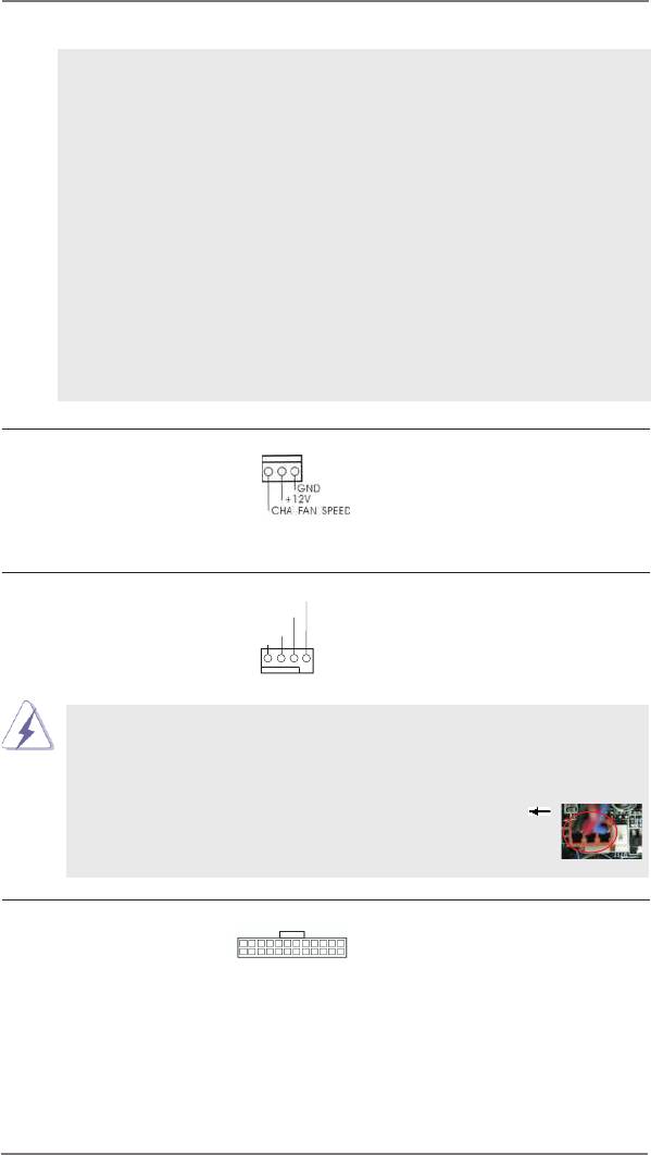
CPU Fan Connectors Please connect the CPU fan
FAN_SPEED_CONTROL
CPU_FAN_SPEED
(4-pin CPU_FAN1)
cable to the connector and
+ 12V
GND
(see p.14 No. 18)
match the black wire to the
ground pin.
1 2 3 4
Though this motherboard provides 4-Pin CPU fan (Quiet Fan) support, the 3-Pin
CPU fan still can work successfully even without the fan speed control function.
If you plan to connect the 3-Pin CPU fan to the CPU fan connector on this
motherboard, please connect it to Pin 1-3.
Pin 1-3 Connected
3-Pin Fan Installation
ATX Power Connector Please connect an ATX power
24 13
(24-pin ATXPWR1)
supply to this connector.
(see p.14 No. 10)
12 1
30
Though this motherboard provides 24-pin ATX power connector, it can still work if
you adopt a traditional 20-pin ATX power supply. To use the 20-pin ATX power
supply, please plug your power supply along with Pin 1 and Pin 13.
24 13
20-Pin ATX Power Supply Installation
12 1
ATX 12V Power Connector Please connect an ATX 12V
(4-pin ATX12V1)
power supply to this connector.
(see p.14 No. 19)
HDMI_SPDIF Header HDMI_SPDIF header, providing
(2-pin HDMI_SPDIF1)
SPDIF audio output to HDMI
1
GND
(
see p.14 No. 16)
VGA card, allows the system to
SPDIFOUT
connect HDMI Digital TV/
projector/LCD devices. Please
connect the HDMI_SPDIF
connector of HDMI VGA card to
this header.
Chassis Intrusion Header This motherboard supports
1
(2-pin CI1)
CASE OPEN detection feature
GND
(see p.14, No. 11)
that detects if the chassis cover
Signal
has been removed. This feature
requires a chassis with chassis
intrusion detection design.
31
2.11 Serial ATA (SATA) / Serial ATA2 (SATA2) Hard Disks
Installation
®
This motherboard adopts Intel
H61 chipset that supports Serial ATA (SATA) / Serial
ATA2 (SATA2) hard disks. You may install SATA / SATA2 hard disks on this mother-
board for internal storage devices. This section will guide you to install the SATA /
SATA2 hard disks.
STEP 1: Install the SATA / SATA2 hard disks into the drive bays of your chassis.
STEP 2: Connect the SATA power cable to the SATA / SATA2 hard disk.
STEP 3: Connect one end of the SATA data cable to the motherboard’s SATA2 con-
nector.
STEP 4: Connect the other end of the SATA data cable to the SATA / SATA2 hard
disk.
2.12 Hot Plug Function for SATA / SATA2 HDDs
This motherboard supports Hot Plug function for SATA / SATA2 in AHCI mode.
®
Intel
H61 chipset provides hardware support for Advanced Host controller Interface
(AHCI), a new programming interface for SATA host controllers developed thru a
joint industry effort.
NOTE
What is Hot Plug Function?
If the SATA / SATA2 HDDs are NOT set for RAID conguration, it is called “Hot
Plug” for the action to insert and remove the SATA / SATA2 HDDs while the
system is still power-on and in working condition.
However, please note that it cannot perform Hot Plug if the OS has been
installed into the SATA / SATA2 HDD.
32
2.13 SATA / SATA2 HDD Hot Plug Feature and Operation Guide
This motherboard supports Hot Plug feature for SATA / SATA2 HDD in AHCI mode.
Please read below operation guide of Hot Plug feature carefully. Before you process
the SATA / SATA2 HDD Hot Plug, please check below cable accessories from the
motherboard gift box pack.
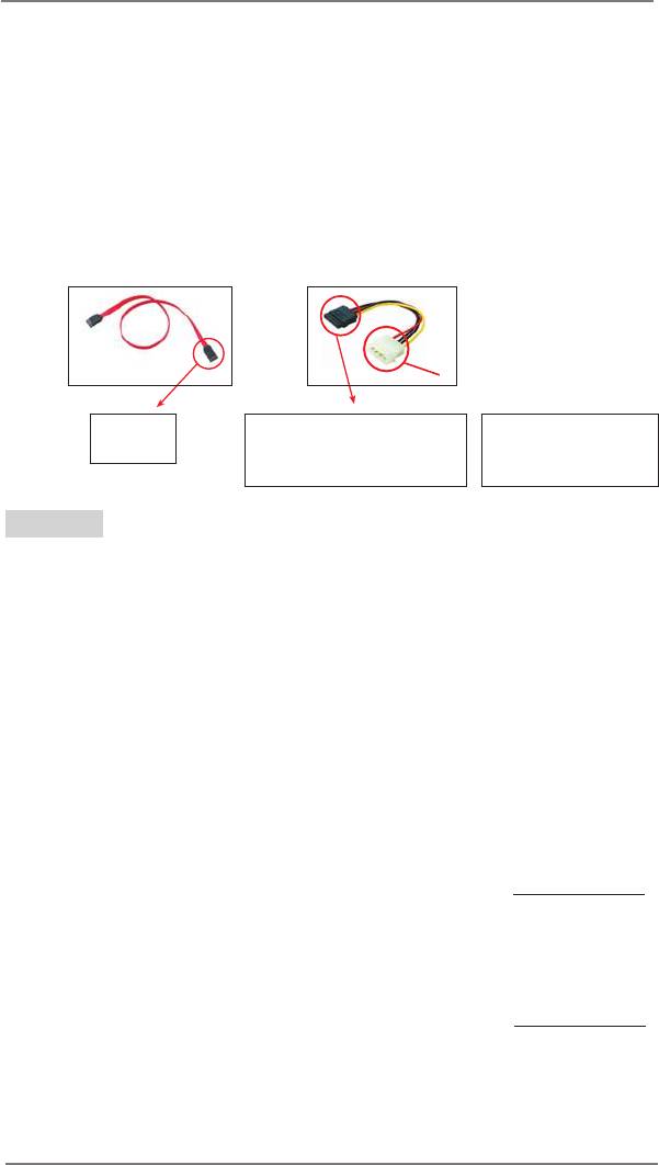
A. 7-pin SATA data cable
B. SATA power cable with SATA 15-pin power connector interface
A. SATA data cable (Red) B. SATA power cable
SATA 7-pin
The SATA 15-pin power
1x4-pin conventional
connector
connector (Black) connect
power connector (White)
to SATA / SATA2 HDD
connect to power supply
Caution
1. Without SATA 15-pin power connector interface, the SATA / SATA2 Hot Plug
cannot be processed.
2. Even some SATA / SATA2 HDDs provide both SATA 15-pin power connector and
IDE 1x4-pin conventional power connector interfaces, the IDE 1x4-pin
conventional power connector interface is denitely not able to support Hot Plug
and will cause the HDD damage and data loss.
Points of attention, before you process the Hot Plug:
1. Below operation procedure is designed only for our motherboard, which supports
SATA / SATA2 HDD Hot Plug.
* The SATA / SATA2 Hot Plug feature might not be supported by the chipset
because of its limitation, the SATA / SATA2 Hot Plug support information of our
motherboard is indicated in the product spec on our website: www.asrock.com
2. Make sure your SATA / SATA2 HDD can support Hot Plug function from your
dealer or HDD user manual. The SATA / SATA2 HDD, which cannot support Hot
Plug function, will be damaged under the Hot Plug operation.
3. Please make sure the SATA / SATA2 driver is installed into system properly. The
latest SATA / SATA2 driver is available on our support website: www.asrock.com
4. Make sure to use the SATA power cable & data cable, which are from our
motherboard package.
5. Please follow below instructions step by step to reduce the risk of HDD crash
or data loss.
33
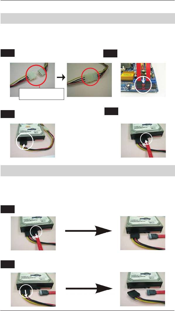
How to Hot Plug a SATA / SATA2 HDD:
Points of attention, before you process the Hot Plug:
Please do follow below instruction sequence to process the Hot Plug, improper
procedure will cause the SATA / SATA2 HDD damage and data loss.
Step 1
Please connect SATA power cable 1x4-pin end
Step 2
Connect SATA data cable to
(White) to the power supply 1x4-pin cable.
the motherboard’s SATA2 connector.
SATA power cable 1x4-pin
power connector (White)
Step 4
Step 3
Connect SATA 15-pin power cable connector
Connect SATA data cable to
(Black) end to SATA / SATA2 HDD.
the SATA / SATA2 HDD.
How to Hot Unplug a SATA / SATA2 HDD:
Points of attention, before you process the Hot Unplug:
Please do follow below instruction sequence to process the Hot Unplug, improper
procedure will cause the SATA / SATA2 HDD damage and data loss.
Step 1
Unplug SATA data cable from SATA / SATA2 HDD side.
Step 2
Unplug SATA 15-pin power cable connector (Black) from SATA / SATA2 HDD side.
34

2.14 Driver Installation Guide
To install the drivers to your system, please insert the support CD to your optical
drive rst. Then, the drivers compatible to your system can be auto-detected and
listed on the support CD driver page. Please follow the order from up to bottom side
to install those required drivers. Therefore, the drivers you install can work properly.
®
TM
2.15 Installing Windows
8 / 8 64-bit / 7 / 7 64-bit / Vista
/
TM
Vista
64-bit / XP / XP 64-bit Without RAID Functions
®
TM
TM
If you want to install Windows
8 / 8 64-bit / 7 / 7 64-bit / Vista
/ Vista
64-bit / XP
/ XP 64-bit OS on your SATA / SATA2 HDDs without RAID functions, please follow
below procedures according to the OS you install.
®
2.15.1 Installing Windows
XP / XP 64-bit Without RAID
Functions
®
If you want to install Windows
XP / XP 64-bit OS on your SATA / SATA2 HDDs
without RAID functions, please follow below steps.
Using SATA / SATA2 HDDs with NCQ function
STEP 1: Set Up UEFI.
A. Enter UEFI SETUP UTILITY Advanced screen Storage Conguration.
B. Set the option “SATA Mode Selection” to [AHCI].
STEP 2: Make a SATA / SATA2 driver diskette. (Please use an USB oppy or a
oppy disk.)
A. Insert the Support CD into your optical drive to boot your system.
B. During POST at the beginning of system boot-up, press <F11> key, and then a
window for boot devices selection appears. Please select CD-ROM as the boot
device.
C. When you see the message on the screen, “Do you want to generate Serial
ATA driver diskette [YN]?”, press <Y>.
D. Then you will see these messages,
Please insert a diskette into the oppy drive.
WARNING! Formatting the oppy diskette will
lose ALL data in it!
Start to format and copy les [YN]?
Please insert a oppy diskette into the oppy drive, and press <Y>.
E. The system will start to format the oppy diskette and copy SATA / SATA2 drivers
into the oppy diskette.
35
®
STEP 3: Install Windows
XP / XP 64-bit OS on your system.
®
After making a SATA / SATA2 driver diskette, you can start to install Windows
XP
®
/ XP 64-bit on your system. At the beginning of Windows
setup, press F6 to install
a third-party AHCI driver. When prompted, insert the SATA / SATA2 driver diskette
®
containing the Intel
AHCI driver. After reading the oppy disk, the driver will be pre-
sented. Select the driver to install according to the mode you choose and the OS
you install.
Using SATA / SATA2 HDDs without NCQ function
STEP 1: Set up UEFI.
A. Enter UEFI SETUP UTILITY Advanced screen Storage Conguration.
B. Set the option “SATA Mode Selection” to [IDE].
®
STEP 2: Install Windows
XP / XP 64-bit OS on your system.
®
TM
2.15.2 Installing Windows
8 / 8 64-bit / 7 / 7 64-bit / Vista
/
TM
Vista
64-bit Without RAID Functions
®
TM
TM
If you want to install Windows
8 / 8 64-bit / 7 / 7 64-bit / Vista
/ Vista
64-bit OS
on your SATA / SATA2 HDDs without RAID functions, please follow below steps.
Using SATA / SATA2 HDDs with NCQ function
STEP 1: Set Up UEFI.
A. Enter UEFI SETUP UTILITY Advanced screen Storage Conguration.
B. Set the option “SATA Mode Selection” to [AHCI].
®
TM
TM
STEP 2: Install Windows
8 / 8 64-bit / 7 / 7 64-bit / Vista
/ Vista
64-bit OS on
your system.
Using SATA / SATA2 HDDs without NCQ function
STEP 1: Set up UEFI.
A. Enter UEFI SETUP UTILITY Advanced screen Storage Conguration.
B. Set the option “SATA Mode Selection” to [IDE].
®
TM
TM
STEP 2: Install Windows
8 / 8 64-bit / 7 / 7 64-bit / Vista
/ Vista
64-bit OS on
your system.
36

2.16 ASRock XFast 555
ASRock’s unique XFast 555 Technology includes three tools that allow users to
experience huge performance boosts. There is XFast RAM for 5 times better system
speed, XFast LAN for 5 times faster LAN speed and XFast USB for 5 times faster
USB speed.
37

2.16.1 ASRock XFast RAM
ASRock XFast RAM is a new function that is included in ASRock Extreme Tuning
Utility (AXTU). It fully utilizes the memory space that cannot be used under Win-
®
dows
32-bit OS. ASRock XFast RAM shortens the loading time of previously visited
websites, making web surng faster than ever. And it also boosts the speed of
Adobe Photoshop 5 times faster. Another advantage of ASRock XFast RAM is that
it reduces the frequency of accessing your SSDs or HDDs in order to extend their
lifespan.
38
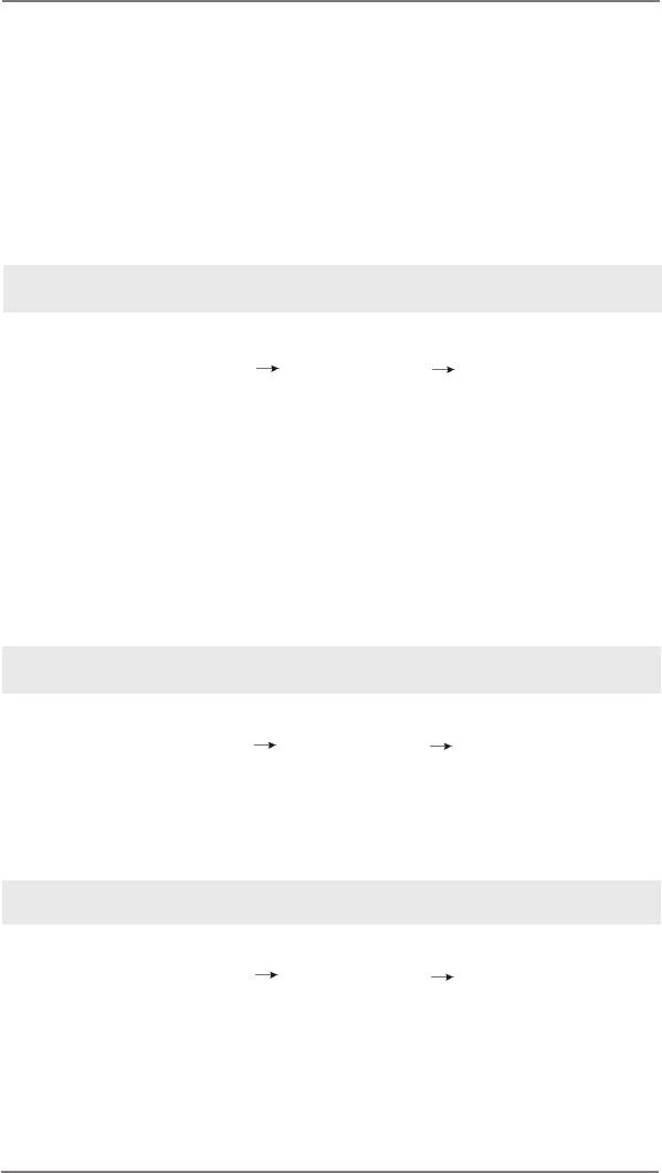
XFast RAM Settings
You may nd the XFast RAM setup page in the left panel of ASRock Extreme Tun-
ing utility.
First select the desired drive and disk size to create a virtual drive.
®
To access more than 4GB of RAM in Windows
32-bit OS, please leave PAE mode
set to ON.
In the options section, users may enable and assign the size of a partition for Ready
Boost if they’re using a 32-bit OS. We suggest setting the size of Ready Boost one
to three times larger than your RAM for optimized performance.
Normally, when the memory being used by all the existing processes exceeds the
available RAM, the operating system moves pages (4-KB pieces) of one or more
virtual address spaces to the computer’s hard disk. By enabling Memory Pagele,
the system puts the pages into the virtual drive instead of the hard disk drive to ac-
celerate performance speed.
39

Lastly, select the les that are supposed to go in the virtual drive to speed up the
system’s performance. Such as temporary les created by computer programs when
they cannot allocate enough memory for its tasks. Or internet cache les including
html, images, Cascading Style Sheets and
JavaScript scripts from IE, Firefox and Google Chrome.
Click Backup XFast RAM if you wish to make a backup. Then click on the APPLY
button to activate XFast RAM. Click on STOP if you wish to deactivate XFastRAM.
The virtual disk will appear once you restart the system.
40

2.16.2 ASRock XFast LAN
ASRock XFast LAN provides several special features for faster internet access. For
example, LAN Application Prioritization allows you to congure your application’s pri-
ority ideally or add new programs to the priority list. Trafc Shaping helps you watch
Youtube HD videos and download les simultaneously without hiccups. And in the
status window there’s Real-Time Analysis of Your Data so you can easily recognize
the data streams you are transferring currently.
41
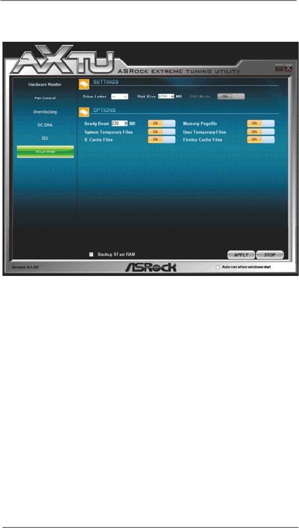
ASRock XFast LAN UI Overview
The default status window
Low Latency Mode switch
arrow down = currently
Open slot
on (if needed)
conguration
arrow up = always on
Download activity display
dialog
no arrow = off
Open Current
TX shaping
Connections window
indicator
Ping time in ms
Show/hide slot
Number of TCP/
activation area
UDP/TCP+UDP
Variance of
connections
ping time
Download CPS rate
Upload CPS rateGraphs Transfer rate
in % for slots 1-10
Upload activity display
Right click for more options
42

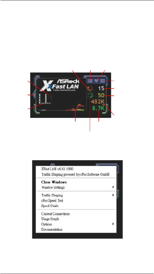
Close Windows
Hides the status window. Can also be done by double clicking on the status
window. Reopen by right clicking on the XFast LAN icon on the
bottom right and selecting Open windows.
Window settings
Users may congure the skin and effects of the user interface. Make the
keyboard LEDs display Trafc Shaping information. Or display the XFast
LAN status window on a Logitech gamer keyboard instead of Windows
desktop.
Trafc Shaping
Trafc Shaping is used to optimize or guarantee performance, improve
latency, and/or increase usable bandwidth for some kinds of packets by
delaying other kinds of packets that meet certain criteria. In other words, it
increases the speed while keeping the overall ping time low.
cFos Speed Test
Quickly test the upload and download speed of your Internet connection.
Speed Guide
This guide can either help you get the maximum out of your connection or
solve problems with speed, ping time or connections.
Current Connection
Shows the details of current internet connections.
Usage Graph
Displays the Usage Graph.
Options
Congure settings such as program prioritization, language and update the
program.
Documentation
Opens detailed help for XFast LAN in a browser.
43
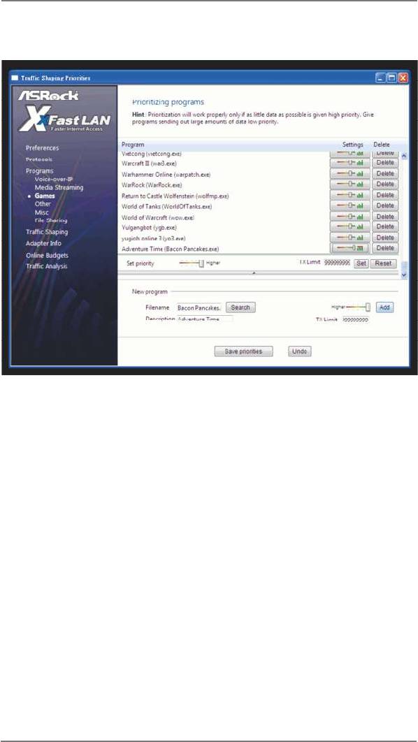
Adding a new application and changing its priority
Click search and choose a new program you wish to add. You can also type in a
short description for the program.
Set the priority for the program and TX Limit then click Add to conrm.
Hit the switch button to change congurations or Delete to remove the application
from the priority list.
44

2.16.3 ASRock XFast USB
Not only does ASRock XFast USB boost up the performance of USB 2.0 storage
devices, but also USB 3.0 devices. Users may experience up to ve times faster
USB data transfer speed!
45
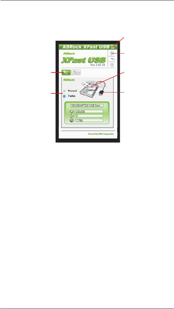
ASRock XFast USB UI Overview
Hide the XFast USB
window
Select your language
Select a connected USB
Click to activate/
storage device
deactivate Turbo mode
Select Normal mode or
Click to safely remove
Turbo mode
the USB hard drive
Plug in your USB storage device and XFast USB automatically sets it to Turbo
mode!
46


