ASRock h61mv-itx: instruction
Class: Computer equipment, hardware, accessories
Type: Motherboard
Manual for ASRock h61mv-itx
1
ASRock H61MV-ITX Motherboard
English
Copyright Notice:
No part of this installation guide may be reproduced, transcribed, transmitted, or trans-
lated in any language, in any form or by any means, except duplication of documentation
by the purchaser for backup purpose, without written consent of ASRock Inc.
Products and corporate names appearing in this guide may or may not be registered
trademarks or copyrights of their respective companies, and are used only for identi
fi
ca-
tion or explanation and to the owners’ bene
fi
t, without intent to infringe.
Disclaimer:
Speci
fi
cations and information contained in this guide are furnished for informational use
only and subject to change without notice, and should not be constructed as a commit-
ment by ASRock. ASRock assumes no responsibility for any errors or omissions that may
appear in this guide.
With respect to the contents of this guide, ASRock does not provide warranty of any kind,
either expressed or implied, including but not limited to the implied warranties or condi-
tions of merchantability or
fi
tness for a particular purpose. In no event shall ASRock, its
directors, of
fi
cers, employees, or agents be liable for any indirect, special, incidental, or
consequential damages (including damages for loss of pro
fi
ts, loss of business, loss of
data, interruption of business and the like), even if ASRock has been advised of the pos-
sibility of such damages arising from any defect or error in the guide or product.
This device complies with Part 15 of the FCC Rules. Operation is subject to the following
two conditions:
(1) this device may not cause harmful interference, and
(2) this device must accept any interference received, including interference that
may cause undesired operation.
CALIFORNIA, USA ONLY
The Lithium battery adopted on this motherboard contains Perchlorate, a toxic substance
controlled in Perchlorate Best Management Practices (BMP) regulations passed by the
California Legislature. When you discard the Lithium battery in California, USA, please
follow the related regulations in advance.
“Perchlorate Material-special handling may apply, see
www.dtsc.ca.gov/hazardouswaste/perchlorate”
ASRock Website: http://www.asrock.com
Published November 2012
Copyright
©
2012 ASRock INC. All rights reserved.
2
ASRock H61MV-ITX Motherboard
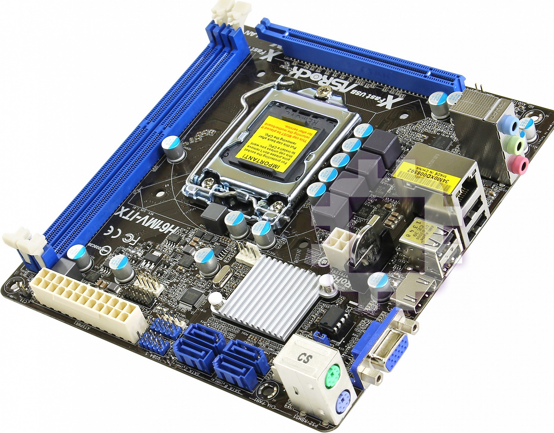
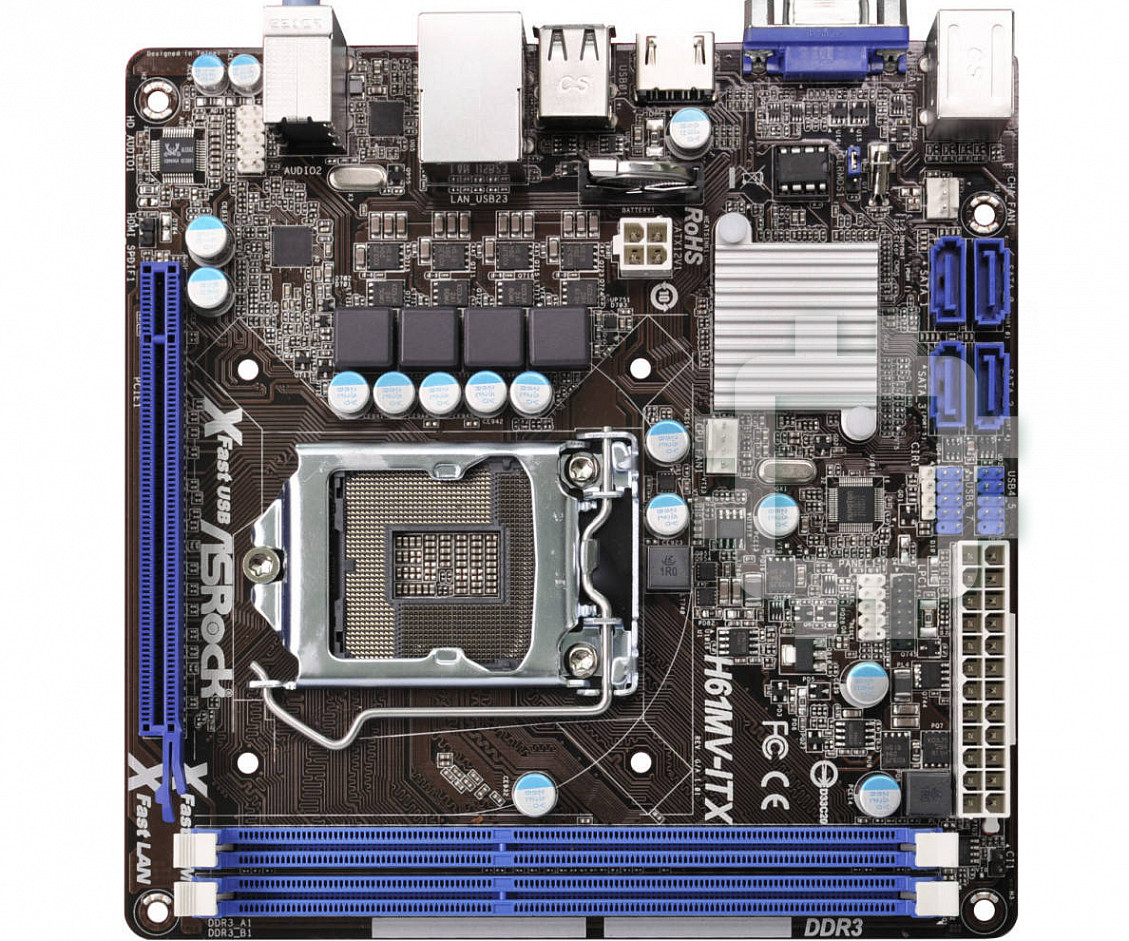
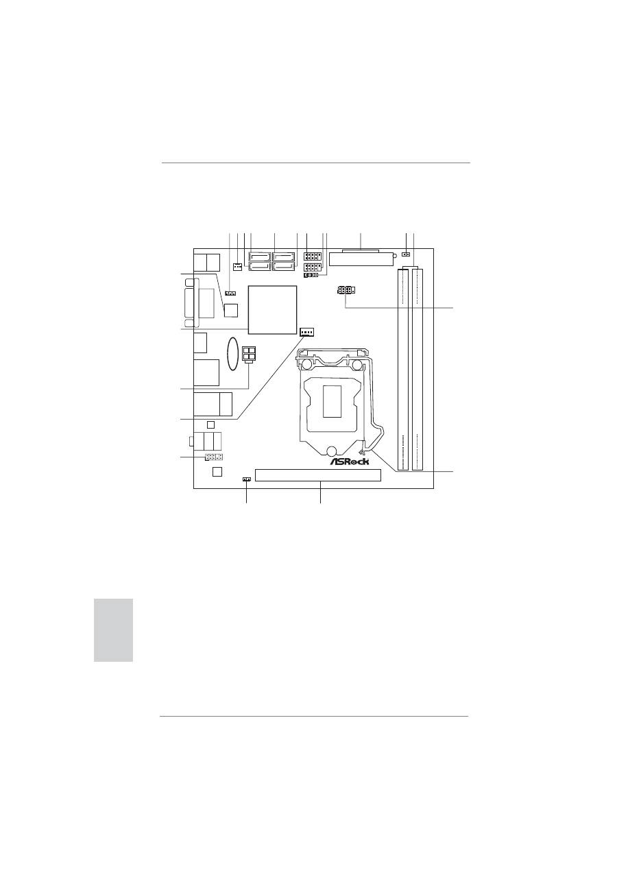
Motherboard Layout
English
1
Clear CMOS Jumper (CLRCMOS1)
12
2 x 240-pin DDR3 DIMM Slots
2
Chassis Fan Connector (CHA_FAN1)
(Dual Channel: DDR3_A1, DDR3_B1)
3
SATA2 Connector (SATA_1 (PORT 1))
13
System Panel Header (PANEL1)
4
SATA2 Connector (SATA_0 (PORT 0))
14
1155-Pin CPU Socket
5
SATA2 Connector (SATA_2 (PORT 4))
15
PCI Express 3.0 x16 Slot (PCIE1)
6
SATA2 Connector (SATA_3 (PORT 5))
16
HDMI_SPDIF Header (HDMI_SPDIF1)
7
USB 2.0 Header (USB4_5)
17
Front Panel Audio Header (HD_AUDIO1)
8
USB 2.0 Header (USB6_7)
18
CPU Fan Connector (CPU_FAN1)
9
Consumer Infrared Module Header (CIR1)
19
ATX 12V Power Connector (ATX12V1)
10
ATX 12V Power Connector (ATX12V1)
20
Intel H61 Chipset
11
Chassis Intrusion Header (CI1)
21
32Mb SPI Flash
DDR3_A1
(64
b
it,
2
40-pin
module)
DDR3_B1
(64
b
it,
2
40-pin
module)
Intel
H61
H61MV-ITX
PCIE1
AUDIO
CODEC
32Mb
BIOS
ATXPWR1
ATX12V1
USB4_5
1
1
USB6_7
HDLED RESET
PLED PWRBTN
PANEL1
CLRCMOS1
1
1
CIR1
1
CHA_FAN1
CPU_FAN1
1
HD_AUDIO1
T
op:
LINE
IN
Center:
FRONT
Bottom:
MIC
IN
Top:
RJ-45
USB 2.0
T: USB2
B: USB3
VGA1
HDMI1
1
2 3 4
5
6
11 12
10
7
8 9
14
13
15
16
17
18
SATA_1 (PORT 1)
USB 2.0
T: USB0
B: USB1
SATA_0 (PORT 0)
SATA_2 (PORT 4)
X
Fast USB
DDR3
19
RoHS
PS2
Keyboard
PS2
Mouse
SATA_3 (PORT 5)
CMOS
Battery
X
Fast RAM
X
Fast LAN
LAN
1
HDMI_SPDIF1
21
1
CI1
20
3
ASRock H61MV-ITX Motherboard
English
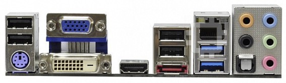
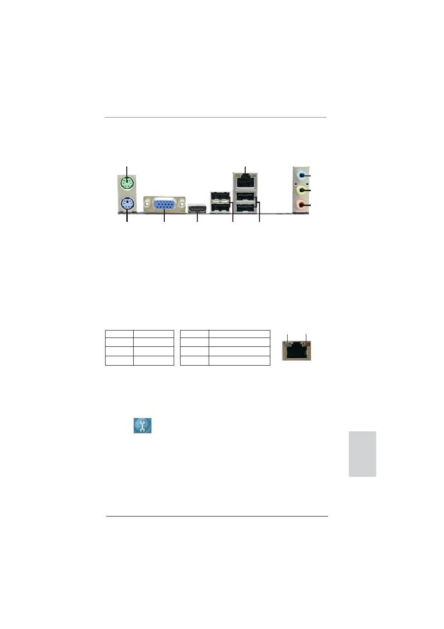
I/O Panel
* There are two LED next to the LAN port. Please refer to the table below for the LAN port LED
indications.
LAN Port LED Indications
Activity/Link LED
SPEED LED
Status Description Status Description
Off No Link Off 10Mbps connection
Blinking Data Activity Orange 100Mbps connection
On Link
Green 1Gbps connection
ACT/LINK
LED
SPEED
LED
LAN Port
1
PS/2 Mouse Port (Green)
6
USB 2.0 Ports (USB23)
* 2
LAN RJ-45 Port
7
USB 2.0 Ports (USB01)
3
Line In (Light Blue)
8
HDMI Port
** 4
Front Speaker (Lime)
9
D-Sub Port
5
Microphone (Pink)
10 PS/2 Keyboard Port (Purple)
1
2
5
3
6
7
8
9
4
10
** To enable Multi-Streaming function, you need to connect a front panel audio cable to the front
panel audio header. Please refer to below steps for the software setting of Multi-Streaming.
For Windows
®
XP:
After restarting your computer, you will
fi
nd “Mixer” tool on your system. Please select “Mixer
ToolBox” , click “Enable playback multi-streaming”, and click “ok”. Choose “2CH” or
“4CH” and then you are allowed to select “Realtek HDA Primary output” to use Rear Speaker
and Front Speaker, or select “Realtek HDA Audio 2nd output” to use front panel audio. Then
reboot your system.
For Windows
®
8 / 7 / Vista
TM
:
After restarting your computer, please double-click “Realtek HD Audio Manager” on the
system tray. Set “Speaker Con
fi
guration” to “Quadraphonic” or “Stereo”. Click “Device
advanced settings”, choose “Make front and rear output devices playbacks two different audio
streams simultaneously”, and click “ok”. Then reboot your system.
Table of contents
- Motherboard Layout
- I/O Panel
- 1. Introduction
- 2. BIOS Information


