ASRock 990FX EXTREME4: instruction
Class: Computer equipment, hardware, accessories
Type: Motherboard
Manual for ASRock 990FX EXTREME4
1
ASRock 990FX Extreme4 Motherboard
English
Copyright Notice:
No part of this installation guide may be reproduced, transcribed, transmitted, or trans-
lated in any language, in any form or by any means, except duplication of documentation
by the purchaser for backup purpose, without written consent of ASRock Inc.
Products and corporate names appearing in this guide may or may not be registered
trademarks or copyrights of their respective companies, and are used only for identifi ca-
tion or explanation and to the owners’ benefi t, without intent to infringe.
Disclaimer:
Specifi cations and information contained in this guide are furnished for informational use
only and subject to change without notice, and should not be constructed as a commit-
ment by ASRock. ASRock assumes no responsibility for any errors or omissions that may
appear in this guide.
With respect to the contents of this guide, ASRock does not provide warranty of any kind,
either expressed or implied, including but not limited to the implied warranties or condi-
tions of merchantability or fi tness for a particular purpose. In no event shall ASRock, its
directors, offi cers, employees, or agents be liable for any indirect, special, incidental, or
consequential damages (including damages for loss of profi ts, loss of business, loss of
data, interruption of business and the like), even if ASRock has been advised of the pos-
sibility of such damages arising from any defect or error in the guide or product.
This device complies with Part 15 of the FCC Rules. Operation is subject to the following
two conditions:
(1) this device may not cause harmful interference, and
(2) this device must accept any interference received, including interference that
may cause undesired operation.
CALIFORNIA, USA ONLY
The Lithium battery adopted on this motherboard contains Perchlorate, a toxic substance
controlled in Perchlorate Best Management Practices (BMP) regulations passed by the
California Legislature. When you discard the Lithium battery in California, USA, please
follow the related regulations in advance.
“Perchlorate Material-special handling may apply, see
www.dtsc.ca.gov/hazardouswaste/perchlorate”
ASRock Website: http://www.asrock.com
Published July 2013
Copyright
©
2013 ASRock INC. All rights reserved.
2
ASRock 990FX Extreme4 Motherboard
English
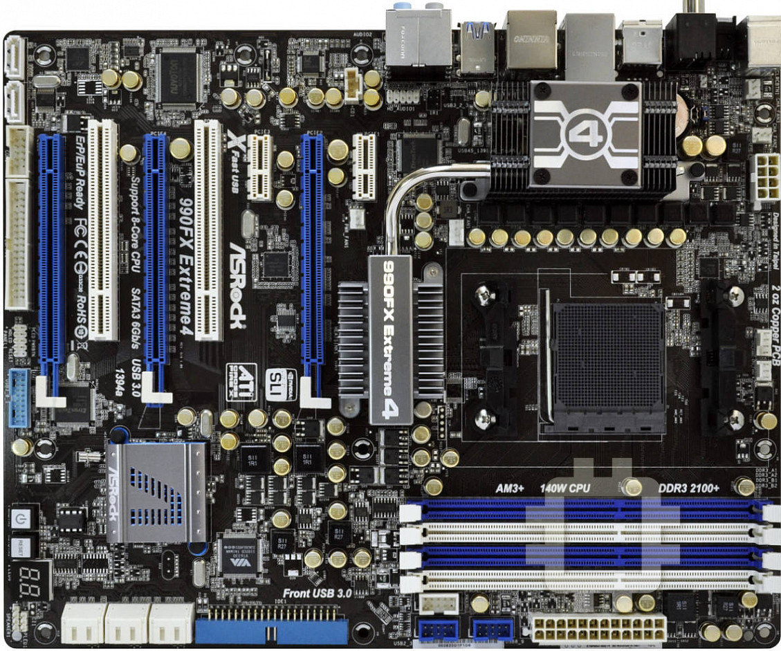
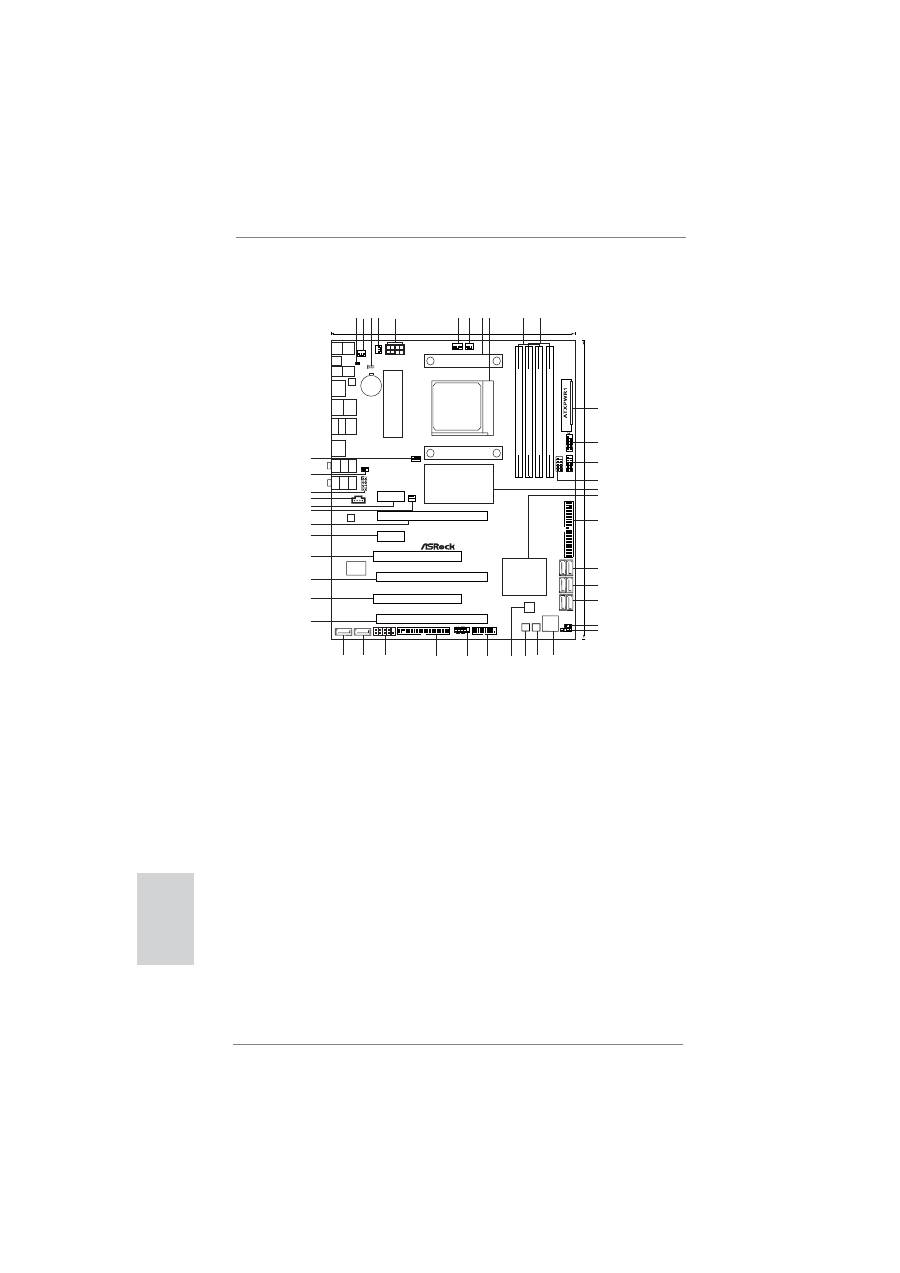
Motherboard Layout
24.4cm (9.6-in)
SOCKET
AM3b
AMD
990FX
Chipset
DDR3_A1
(64
bit,
240-pin
module)
DDR3_A2
(64
bit,
240-pin
module)
DDR3_B1
(64
bit,
240-pin
module)
DDR3_B2
(64
bit,
240-pin
module)
ATX12V1
CPU_FAN2
CPU_FAN1
CHA_FAN2
CHA_FAN3
CLRCMOS1
1
1
USB8_9
1
USB2_3
1
FRONT_1394
1
IDE1
SA
T
A3_5_6
SA
T
A3_3_4
SA
T
A3_1_2
1
PLED1
SPEAKER1
1
Dr.
Debug
PWRBTN1
RSTBTN1
USB3_0_1
HDLED RESET
PLED PWRBTN
1
PANEL 1
FLOPPY1
COM1
1
SATA3_7
SATA3_8
PCIE5
PCI2
PCIE4
PCIE1
PCIE2
PCIE3
PCI1
PWR_FAN1
CD1
HD_AUDIO1
1
CHA_FAN1
IR1
CMOS
BATTERY
LAN
PHY
PS2
Keyboard
Coaxial
SPDIF
Optical
SPDIF
Clr
CMOS
PS2
Mouse
USB
2.0
T:
U
S
B
0
B:
USB1
RJ-45
LAN
USB
2.0
T:
U
S
B
6
B:
USB7
USB
2.0
T:
U
S
B
4
B:
USB5
eSA
TA3
IEEE
1394
USB
3.0
T:
U
S
B
2
B:
USB3
T
op:
SIDE
SPK
Center:
REAR
SPK
Bottom:
CTR
BASS
T
op:
LINE
IN
Center:
FRONT
Bottom:
M
IC I
N
AUDIO
CODEC
32Mb
BIOS
Super
I/O
30.5cm
(12.0-in)
DDR3
1866
HT3.0
Phenom
II
AM3+
FSB2.6GHz
Dual
Channel
140W
CPU
Designed in Taipei
990FX Extreme4
Support 8-Core CPU
PCI Express 2.0
SATA3 6Gb/s
ErP/EuP
Ready
Front USB 3.0
RoHS
1394a
USB 3.0
1
HDMI_SPDIF1
AMD
SB950
Chipset
14
1 2 3 4
5
6 7
8 9
11
12
13
16
15
17
18
19
20
21
22
23
24
24
25
25
26
26
27
28
29
30
31
32
33
34
35
36
37
38
39
40
41
42
43
44
10
45
1
HDMI_SPDIF Header (HDMI_SPDIF1, White)
23
Chassis Speaker Header
2
Chassis Fan Connector (CHA_FAN3)
(SPEAKER 1, White)
3
Clear CMOS Jumper (CLRCMOS1)
24
Dr. Debug (LED)
4
Chassis Fan Connector (CHA_FAN2)
25
Reset Switch (RSTBTN)
5
ATX 12V Power Connector (ATX12V1)
26
Power Switch (PWRBTN)
6
CPU Fan Connector (CPU_FAN1)
27
SPI Flash Memory (32Mb)
7
CPU Fan Connector (CPU_FAN2)
28
USB 3.0 Header (USB3_0_1, Light Blue)
8
CPU Heatsink Retention Module
29
System Panel Header (PANEL1, White)
9
AM3+ CPU Socket
30
Floppy Connector (FLOPPY1)
10
2 x 240-pin DDR3 DIMM Slots
31
Serial Port Connector (COM1)
(Dual Channel B: DDR3_A1, DDR3_B1; Blue)
32
SATA3 Connector (SATA3_7, White)
11
2 x 240-pin DDR3 DIMM Slots
33
SATA3 Connector (SATA3_8, White)
(Dual Channel B: DDR3_A2, DDR3_B2; White) 34
PCI Express 2.0 x16 Slot (PCIE5; Blue)
12
ATX Power Connector (ATXPWR1)
35
PCI Slot (PCI2)
13
USB 2.0 Header (USB8_9, Blue)
36
PCI Express 2.0 x16 Slot (PCIE4; Blue)
14
USB 2.0 Header (USB2_3, Blue)
37
PCI Slot (PCI1)
15
Front Panel IEEE 1394 Header
38
PCI Express 2.0 x1 Slot (PCIE3; White)
(FRONT_1394, White)
39
PCI Express 2.0 x16 Slot (PCIE2; Blue)
16
Northbridge Controller
40
Power Fan Connector (PWR_FAN1)
17
Southbridge Controller
41
PCI Express 2.0 x1 Slot (PCIE1; White)
18
Primary IDE Connector (IDE1, Blue)
42
Internal Audio Connector: CD1 (White)
19
SATA3 Connector (SATA3_5_6, White)
43
Front Panel Audio Header
20
SATA3 Connector (SATA3_3_4, White)
(HD_AUDIO1, White)
21
SATA3 Connector (SATA3_1_2, White)
44
Infrared Module Header (IR1)
22
Power LED Header (PLED1)
45
Chassis Fan Connector (CHA_FAN1)
3
ASRock 990FX Extreme4 Motherboard
English
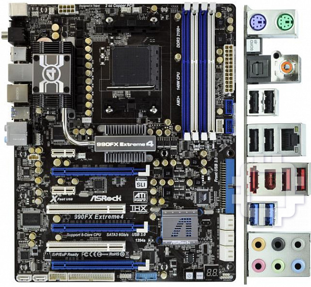
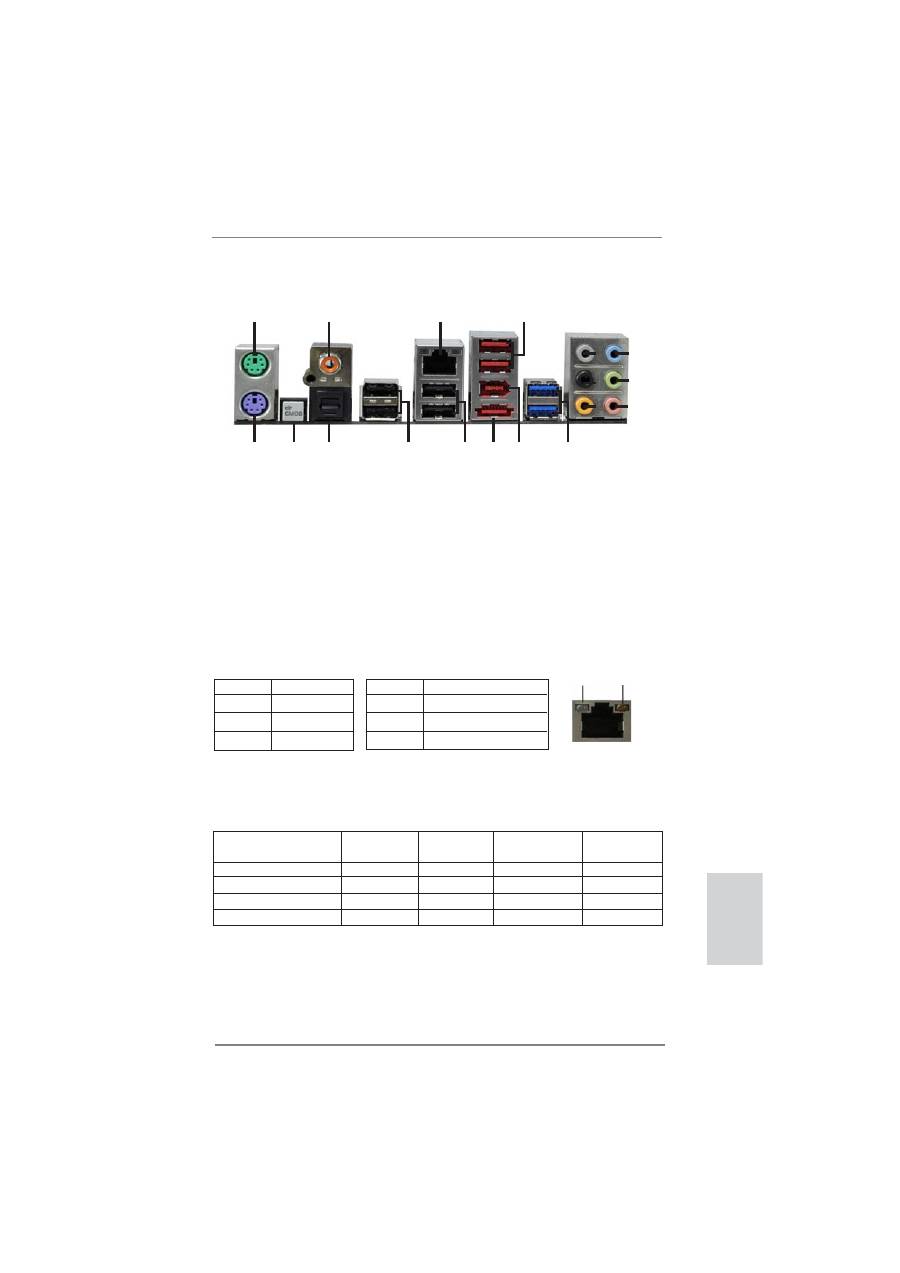
I/O Panel
**
If you use 2-channel speaker, please connect the speaker’s plug into “Front Speaker Jack”.
See the table below for connection details in accordance with the type of speaker you use.
TABLE for Audio Output Connection
Audio Output Channels Front Speaker Rear Speaker
Central / Bass
Side Speaker
(No. 9)
(No. 6)
(No. 7)
(No. 5)
2
V
-- -- --
4 V
V
--
--
6
V
V V --
8
V
V V V
LAN Port
ACT/LINK
LED
SPEED
LED
* There are two LED next to the LAN port. Please refer to the table below for the LAN port LED
indications.
LAN Port LED Indications
Activity/Link LED
SPEED LED
Status Description Status Description
Off No Link Off 10Mbps connection
Blinking Data Activity Orange 100Mbps connection
On Link
Green 1Gbps connection
1
2
4
3
5
6
7
8
9
10
11
12
13
14
15
16
17
18
1
PS/2 Mouse Port (Green)
10 Microphone (Pink)
2
Coaxial SPDIF Out Port
11 USB 3.0 Ports (USB23)
*3
LAN RJ-45 Port
12 IEEE 1394 Port (IEEE 1394)
4
USB 2.0 Ports (USB45) ***13 eSATA3 Connector
5
Side Speaker (Gray)
14 USB 2.0 Ports (USB67)
6
Rear Speaker (Black)
15 USB 2.0 Ports (USB01)
7
Central / Bass (Orange)
16 Optical SPDIF Out Port
8
Line In (Light Blue)
17 Clear CMOS Switch (CLRCBTN)
**9
Front Speaker (Lime)
18 PS/2 Keyboard Port (Purple)

4
ASRock 990FX Extreme4 Motherboard
To enable Multi-Streaming function, you need to connect a front panel audio cable to the front
panel audio header. After restarting your computer, you will
fi
nd “Mixer” tool on your system.
Please select “Mixer ToolBox” , click “Enable playback multi-streaming”, and click “ok”.
Choose “2CH”, “4CH”, “6CH”, or “8CH” and then you are allowed to select “Realtek HDA Pri-
mary output” to use Rear Speaker, Central/Bass, and Front Speaker, or select “Realtek HDA
Audio 2nd output” to use front panel audio.
*** eSATA3 connector supports SATA Gen3 in cable 1M.
English
Table of contents
- Motherboard Layout
- I/O Panel
- 1. Introduction
- 2. Installation
- 3. BIOS Information
- 1. Einführung
- 2. Installation
- 3. BIOS-Information
- 1. Introduction
- 2. Installation
- 3. Informations sur le BIOS
- 1. Introduzione
- 2. Installazione
- 3. Informazioni sul BIOS
- 1. Introducción
- 2. Instalación
- 3. BIOS Información
- 1. Введение
- 2. Установка
- 3.
- 1. Giri ş
- 2. Takma
- 3. BIOS Bilgileri
- 1. 제품소개
- 2. 설치하기
- 3. 시스템 바이오스 정보
- 1. 主板簡介
- 2. 主板安裝
- 3. BIOS 信息
- 1. 主機板簡介
- 2. 主機板安裝
- Installing OS on a HDD Larger Than 2TB


