ASRock Z87 Extreme9__ac: instruction
Class: Computer equipment, hardware, accessories
Type: Motherboard
Manual for ASRock Z87 Extreme9__ac
Version 1.2
Published July 2013
Copyright©2013 ASRock INC. All rights reserved.
Copyright Notice:
No part of this documentation may be reproduced, transcribed, transmitted, or
translated in any language, in any form or by any means, except duplication of
documentation by the purchaser for backup purpose, without written consent of
ASRock Inc.
Products and corporate names appearing in this documentation may or may not
be registered trademarks or copyrights of their respective companies, and are used
only for identication or explanation and to the owners’ benet, without intent to
infringe.
Disclaimer:
Specications and information contained in this documentation are furnished for
informational use only and subject to change without notice, and should not be
constructed as a commitment by ASRock. ASRock assumes no responsibility for
any errors or omissions that may appear in this documentation.
With respect to the contents of this documentation, ASRock does not provide
warranty of any kind, either expressed or implied, including but not limited to
the implied warranties or conditions of merchantability or tness for a particular
purpose.
In no event shall ASRock, its directors, ocers, employees, or agents be liable for
any indirect, special, incidental, or consequential damages (including damages for
loss of prots, loss of business, loss of data, interruption of business and the like),
even if ASRock has been advised of the possibility of such damages arising from any
defect or error in the documentation or product.
is device complies with Part 15 of the FCC Rules. Operation is subject to the following
two conditions:
(1) this device may not cause harmful interference, and
(2) this device must accept any interference received, including interference that
may cause undesired operation.
CALIFORNIA, USA ONLY
e Lithium battery adopted on this motherboard contains Perchlorate, a toxic substance
controlled in Perchlorate Best Management Practices (BMP) regulations passed by the
California Legislature. When you discard the Lithium battery in California, USA, please
follow the related regulations in advance.
“Perchlorate Material-special handling may apply, see www.dtsc.ca.gov/hazardouswaste/
perchlorate”
ASRock Website: http://www.asrock.com
e terms HDMI™ and HDMI High-Denition Multimedia Interface, and the HDMI
logo are trademarks or registered trademarks of HDMI Licensing LLC in the United
States and other countries.
Manufactured under license under U.S. Patent Nos: 5,956,674; 5,974,380; 6,487,535;
7,003,467 & other U.S. and worldwide patents issued & pending. DTS, the Symbol, &
DTS and the Symbol together is a registered trademark & DTS Connect, DTS Interactive,
DTS Neo:PC are trademarks of DTS, Inc. Product includes soware.
© DTS, Inc., All Rights Reserved.
Z87 Extreme9/ac
CMOS
Battery
English
PB 1
1
2
3
48
5
6
7
Keyboard
/Mouse
B: USB1
T: USB0
USB 2.0
PS2
CHA_FAN3
CPU_FAN1
CPU_FAN2
PWR_FAN1
ATX 12V1
ATX 12V2
LAN
RJ-45
RJ-45
LAN2
LAN1
LAN
HDMI1
DP_1
eSATA1
USB 3.0
T: USB0
B: USB1
TB2
USB 3.0
T: USB2
B: USB3
TB1
9
USB 3.0
T: USB4
CLRCBTN1
B: USB5
ATXPWR1
DDR3_A1 (6 4 bit, 240-pin module)
DDR3_A2 (6 4 bit, 240-pin module)
DDR3_B1 (6 4 bit, 240-pin module)
DDR3_B2 (6 4 bit, 240-pin module)
SPD IF
Opt ical
Bot tom:
REA R SPK
Cen ter:
Central/Bass
Top:
10
MIC I N
Bot tom:
FRO NT
Cen ter:
LIN E IN
Top:
11
CHA_FAN2
USB 3_6_7
USB 3_8_9
33
1
1
PCIE1
RoHS
12
PCIE2
SATA3 _A1 _A2
Purity
TM
Sound
13
SATA3 _A3 _A4
PCIE3
14
SATA3 _0_ 1
Z87 Extreme9/ac
Super
I/O
Intel
15
SATA3 _2_ 3
PCIE4
Z87
16
SATA3 _4_ 5
Dr.
BIOS_B_LED
Debug
64Mb
PCIE5
BIOS
BIOS_B
Module
BIOS_A_LED
64Mb
MINI _PCIE 1
CHA_FAN1
BIOS
WiFi-802.11ac
BIOS_A
BIOS _SEL1
AB
17
PCIE6
CLRCMOS1
PLED1
SPEAKER1
1
1
1
18
USB8
SLI/XFIRE_PWR1
IR1
USB2_3
USB4_5
USB6_7
PLED PWRBTN
HD_AUDIO1
COM1
Vertical
Reset
1
Type AUSB
Power
1
1
1
1
HDLED RESET
1
1
PANEL1
27303132
2629
24
23
222528
21
20
19
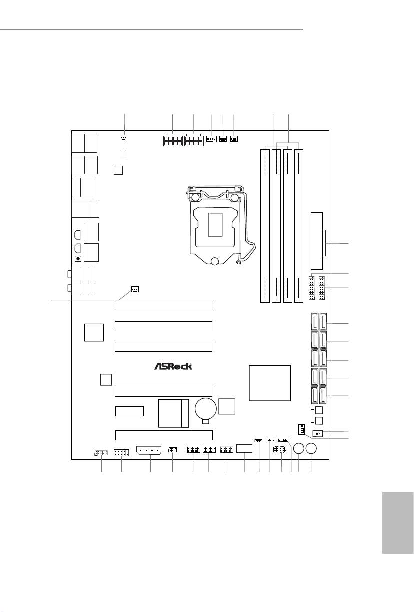
Motherboard Layout
Z87 Extreme9/ac
No. Description
1 Chassis Fan Connector (CHA_FAN3)
2 ATX 12V Power Connector (ATX12V1)
3 ATX 12V Power Connector (ATX12V2)
4 CPU Fan Connector (CPU_FAN1)
5 CPU Fan Connector (CPU_FAN2)
6 Power Fan Connector (PWR_FAN1)
7 2 x 240-pin DDR3 DIMM Slots (DDR3_A1, DDR3_B1)
8 2 x 240-pin DDR3 DIMM Slots (DDR3_A2, DDR3_B2)
9 ATX Power Connector (ATXPWR1)
10 USB 3.0 Header (USB3_6_7) (ASMedia Hub)
11 USB 3.0 Header (USB3_8_9) (ASMedia Hub)
12 SATA3 Connectors (SATA3_A1_A2)
13 SATA3 Connectors (SATA3_A3_A4)
14 SATA3 Connectors (SATA3_0_1)
15 SATA3 Connectors (SATA3_2_3)
16 SATA3 Connectors (SATA3_4_5)
17 BIOS Selection Switch (BIOS_SEL1)
18 Chassis Fan Connector (CHA_FAN1)
19 Power Switch (PWRBTN1)
20 Reset Switch (RSTBTN1)
21 Chassis Speaker Header (SPEAKER1)
22 System Panel Header (PANEL1)
23 Power LED Header (PLED1)
24 Clear CMOS Jumper (CLRCMOS1)
25 Vertical Type A USB 2.0 (USB8)
26 USB 2.0 Header (USB_6_7)
27 USB 2.0 Header (USB4_5)
28 USB 2.0 Header (USB2_3)
29 Infrared Module Header (IR1)
30 SLI/XFIRE Power Connector (SLI/XFIRE_PWR1)
English
31 COM Port Header (COM1)
32 Front Panel Audio Header (HD_AUDIO1)
33 Chassis Fan Connector (CHA_FAN2)
2 3
Z87 Extreme9/ac
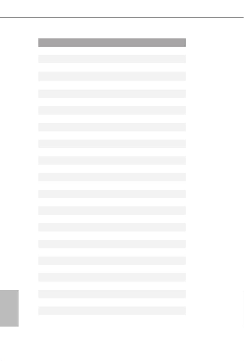
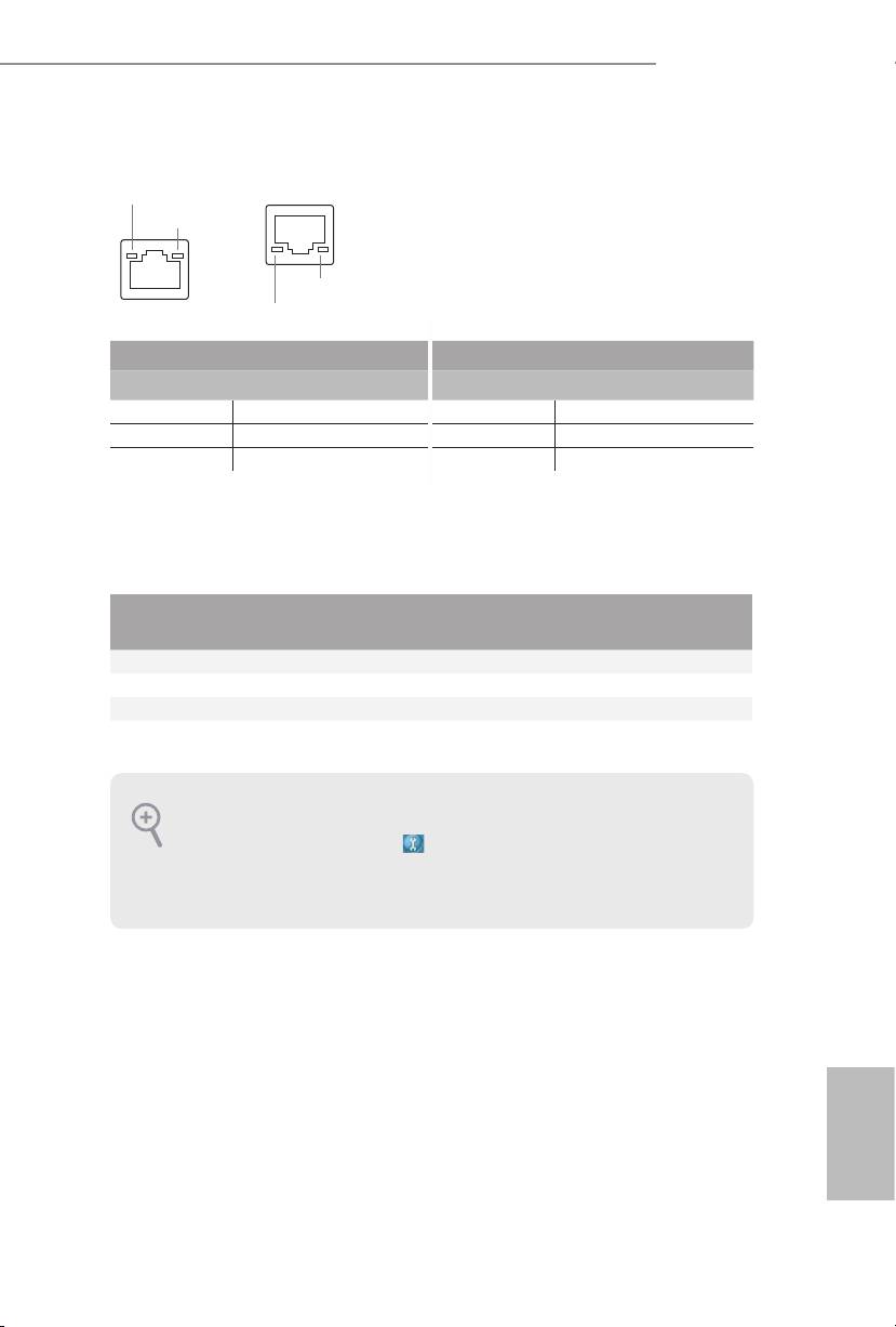
* ere are two LEDs on each LAN port. Please refer to the table below for the LAN port LED indications.
ACT/LINK LED
LAN Port
SPEED LED
SPEED LED
LAN Port
ACT/LINK LED
Activity / Link LED Speed LED
Status Description Status Description
O No Link O 10Mbps connection
Blinking Data Activity Orange 100Mbps connection
On Link Green 1Gbps connection
** If you use a 2-channel speaker, please connect the speaker’s plug into “Front Speaker Jack”. See the table below
for connection details in accordance with the type of speaker you use.
Audio Output
Front Speaker
Rear Speaker
Central / Bass
Line In
Channels
(No. 10)
(No. 8)
(No. 7)
(No. 9)
2 V -- -- --
4 V V -- --
6 V V V --
8 V V V V
To enable Multi-Streaming, you need to connect a front panel audio cable to the front
panel audio header. Aer restarting your computer, you will nd the “Mixer” tool on your
system. Please select “Mixer ToolBox” , click “Enable playback multi-streaming”, and
click “ok”. Choose “2CH”, “4CH”, “6CH”, or “8CH” and then you are allowed to select
“Realtek HDA Primary output” to use the Rear Speaker, Central/Bass, and Front Speaker,
or select “Realtek HDA Audio 2nd output” to use the front panel audio.
*** e eSATA connector supports SATA with cables within 1 meters.
English
2 3
Z87 Extreme9/ac
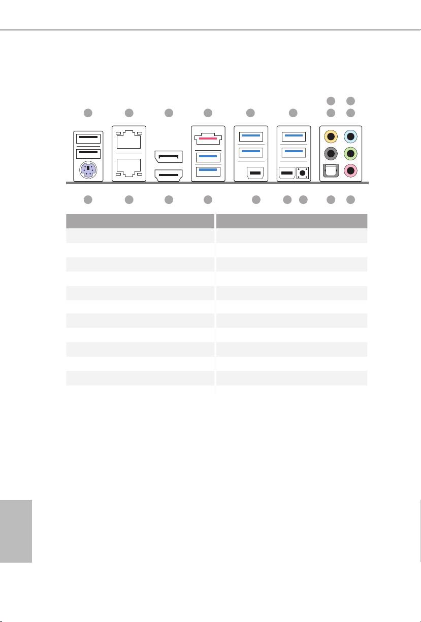
I/O Panel
Chapter 1 Introduction
ank you for purchasing ASRock Z87 Extreme9/ac motherboard, a reliable
7
9
motherboard produced under ASRock’s consistently stringent quality control.
1 2 3 85 64
10
It delivers excellent performance with robust design conforming to ASRock’s
commitment to quality and endurance.
11121315 1416171819
No. Description No. Description
1 USB 2.0 Ports (USB01) 11 Microphone (Pink)
2 LAN RJ-45 Port (Intel® I211AT)* 12 Optical SPDIF Out Port
3 Display Port Input (HDMI_DP_1) 13 Clear CMOS Button
1.1 Package Contents
4 eSATA Connector*** 14 underbolt Port (TBT1)
•
ASRock Z87 Extreme9/ac Motherboard (ATX Form Factor)
5 USB 3.0 Ports (USB3_23) 15 underbolt Port (TBT2)
•
ASRock Z87 Extreme9/ac Quick Installation Guide
(ASMedia Hub) 16 USB 3.0 Ports (USB3_01)
•
ASRock Z87 Extreme9/ac Support CD
6 USB 3.0 Ports (USB3_45) (ASMedia Hub)
•
10 x Serial ATA (SATA) Data Cables (Optional)
7 Central / Bass (Orange) 17 HDMI Port
•
1 x I/O Panel Shield
8 Rear Speaker (Black) 18 LAN RJ-45 Port (Intel® I217V)*
•
2 x ASRock SLI_Bridge Cards
9 Line In (Light Blue) 19 PS/2 Mouse/Keyboard Port
•
1 x ASRock SLI_Bridge_3S Card
•
1 x ASRock 3-Way SLI Bridge Card
10 Front Speaker (Lime)**
•
1 x ASRock Wi-SD Box
•
12 Screws (for Wi-SD Box)
•
1 x USB 3.0 Cable
English
4 5
