ASRock Z77 Extreme9 – страница 2
Инструкция к Материнской Плате ASRock Z77 Extreme9
21
ASRock Z77 Extreme9 Motherboard
English
Installing a DIMM
Please make sure to disconnect power supply before adding or
removing DIMMs or the system components.
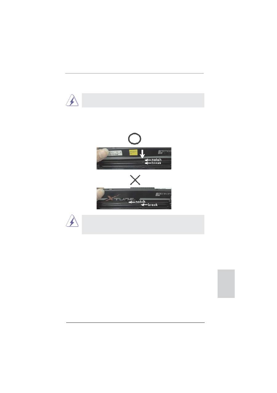
Step 1. Unlock a DIMM slot by pressing the retaining clips outward.
Step 2. Align a DIMM on the slot such that the notch on the DIMM matches the
break on the slot.
The DIMM only
fi
ts in one correct orientation. It will cause permanent
damage to the motherboard and the DIMM if you force the DIMM into
the slot at incorrect orientation.
Step 3. Firmly insert the DIMM into the slot until the retaining clips at both ends
fully snap back in place and the DIMM is properly seated.

22
ASRock Z77 Extreme9 Motherboard
English
2.6 Expansion Slots (PCI Express Slots)
There are 7 PCI Express slots and 1 mini-PCI Express slot on this motherboard.
PCIE slots:
PCIE1 / PCIE5 (PCIE 3.0 x16 slot) is used for PCI Express x16 lane
width graphics cards, or to install PCI Express graphics cards to support
CrossFireX
TM
or SLI
TM
function.
PCIE3 / PCIE7 (PCIE 3.0 x16 slot) is used for PCI Express x8 lane
width graphics cards, or to install PCI Express graphics cards to support
CrossFireX
TM
or SLI
TM
function.
PCIE2 (PCIE 3.0 x16 slot) is used for PCI Express x16 lane width
graphics cards.
PCIE4 (PCIE 2.0 x16 slot) is used for PCI Express x4 lane width graph-
ics cards or ASRock Game Blaster.
PCIE6 (PCIE 2.0 x1 slot) is used for a PCI Express x1 lane width card,
such as a Gigabit LAN card, SATA2 card, etc.
MINI_PCIE1 (mini-PCIE slot) is used for WiFi + BT module.
PCIE Slot Con
fi
gurations
PCIE1 PCIE2 PCIE3 PCIE5 PCIE7
Single Graphics Card
N/A
x16 N/A N/A N/A
Two Graphics Cards in
x16 N/A N/A x16 N/A
CrossFireX
TM
or SLI
TM
Mode
Three Graphics Cards in
x8 N/A x8 x16 N/A
3-Way CrossFireX
TM
or
3-Way SLI
TM
Mode
Four Graphics Cards in
x8 N/A x8 x8 x8
4-Way CrossFireX
TM
or
4-Way SLI
TM
Mode

23
ASRock Z77 Extreme9 Motherboard
English
Installing an expansion card
Step 1.
Before installing an expansion card, please make sure that the power
supply is switched off or the power cord is unplugged. Please read the
documentation of the expansion card and make necessary hardware
settings for the card before you start the installation.
Step 2.
Remove the system unit cover (if your motherboard is already installed
in a chassis).
Step 3.
Remove the bracket facing the slot that you intend to use. Keep the
screws for later use.
Step 4.
Align the card connector with the slot and press
fi
rmly until the card is
completely seated on the slot.
Step 5.
Fasten the card to the chassis with screws.
Step 6.
Replace the system cover.
1. In single VGA card mode, it is recommended to install a PCI Express
x16 graphics card in the PCIE2 slot.
2. PCIE1, PCIE3, PCIE5 and PCIE7 slots will be disabled if PCIE2 slot
is occupied.
3. In CrossFireX
TM
mode or SLI
TM
mode, please install the PCI Express
x16 graphics cards in PCIE1 and PCIE5 slots. Both these two slots
will work at x16 bandwidth.
4. In 3-Way CrossFireX
TM
or 3-Way SLI
TM
mode, please install the PCI
Express x16 graphics cards in PCIE1, PCIE3 and PCIE5 slots. PCIE1
and PCIE3 will work at x8 bandwidth, while PCIE5 works at x16
bandwidth.
5. In 4-Way CrossFireX
TM
or 4-Way SLI
TM
mode, please install the PCI
Express x16 graphics cards in PCIE1, PCIE3, PCIE5 and PCIE7
slots. All these four slots will work at x8 bandwidth.
6. Please connect a chassis fan to the motherboard’s chassis fan
connector (CHA_FAN1, CHA_FAN2 or CHA_FAN3) when using
multiple graphics cards for better thermal environment.
7.
Only
PCIE1, PCIE2, PCIE3, PCIE5, PCIE6 and PCIE7 slots
support
Gen 3 speed. To run the PCI Express in Gen 3 speed, please install
an Ivy Bridge CPU. If you install a Sandy Bridge CPU, the PCI
Express will run only at PCI Express Gen 2 speed.
24
ASRock Z77 Extreme9 Motherboard
English
2.7 SLI
TM
, 3-Way SLI
TM
, 4-Way SLI
TM
and Quad SLI
TM
Operation
Guide
This motherboard supports NVIDIA
®
SLI
TM
, 3-Way SLI
TM
, 4-Way SLI
TM
and Quad
SLI
TM
(Scalable Link Interface) technology that allows you to install up to four
identical PCI Express x16 graphics cards. Currently, NVIDIA
®
SLI
TM
technology
supports Windows
®
XP / XP 64-bit / Vista
TM
/ Vista
TM
64-bit / 7 / 7 64-bit OS. NVIDIA
®
3-Way SLI
TM
, 4-Way SLI
TM
and Quad SLI
TM
technology supports Windows
®
Vista
TM
/
Vista
TM
64-bit / 7 / 7 64-bit OS only. Please follow the installation procedures in this
section.
2.7.1 Graphics Card Setup
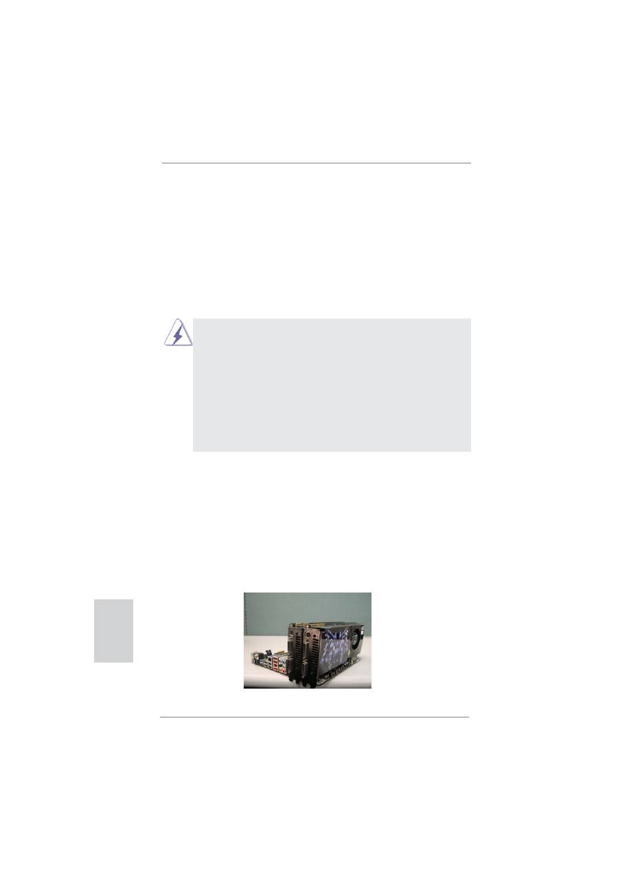
2.7.1.1 Installing Two SLI
TM
-Ready Graphics Cards
Step 1. Install identical SLI
TM
-ready graphics cards that are NVIDIA
®
certi
fi
ed be-
cause different types of graphics cards will not work together properly. (Even
the GPU chips version shall be the same.) Insert one graphics card into
PCIE1 slot and the other graphics card to PCIE5 slot. Make sure that the
cards are properly seated on the slots.
Requirements
1. For SLI
TM
technology, you should have two identical SLI
TM
-ready graphics
cards that are NVIDIA
®
certi
fi
ed. For 3-Way SLI
TM
technology you should
have three, whereas for 4-Way SLI
TM
technology you should have four. For
Quad SLI
TM
technology, you should have two identical Quad SLI
TM
-ready
graphics cards that are NVIDIA
®
certi
fi
ed.
2. Make sure that your graphics card driver supports NVIDIA
®
SLI
TM
technology.
Download the driver from NVIDIA website (www.nvidia.com).
3. Make sure that your power supply unit (PSU) can provide at least the
minimum power required by your system. It is recommended to use NVIDIA
®
certi
fi
ed PSU. Please refer to NVIDIA
®
website for details.
25
ASRock Z77 Extreme9 Motherboard
English
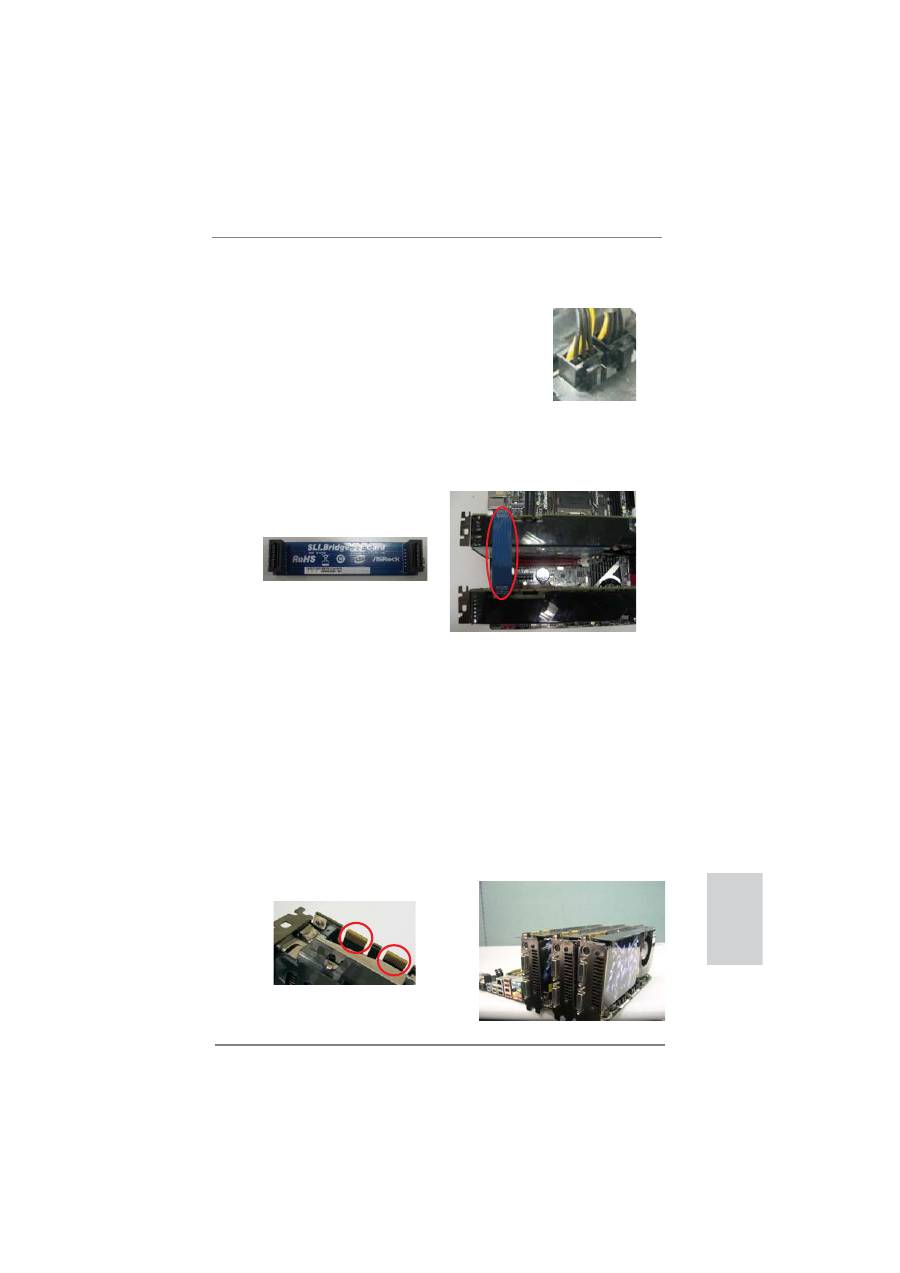
Step4. Connect a VGA cable or a DVI cable to the monitor connector or the DVI
connector of the graphics card that is inserted to PCIE1 slot.
Step3. Align and insert the ASRock SLI_Bridge_3S Card to the gold
fi
ngers on
each graphics card. Make sure the ASRock SLI_Bridge_3S Card is
fi
rmly
in place.
ASRock SLI_Bridge_3S Card
Step2. If required, connect the auxiliary power source to the PCI Express graph-
ics cards.
2.7.1.2 Installing Three SLI
TM
-Ready Graphics Cards
Step 1. Install identical 3-Way SLI
TM
-ready graphics cards that are NVIDIA
®
certi-
fi
ed because different types of graphics cards will not work together prop-
erly. (Even the GPU chips version shall be the same.) Each graphics card
should have two gold
fi
ngers for the 3-Way SLI Bridge connector. Insert
one graphics card into PCIE1 slot, another graphics card to PCIE3 slot,
and the other graphics card to PCIE5 slot. Make sure that the cards are
properly seated on the slots.
Two Gold
fi
ngers
26
ASRock Z77 Extreme9 Motherboard
English
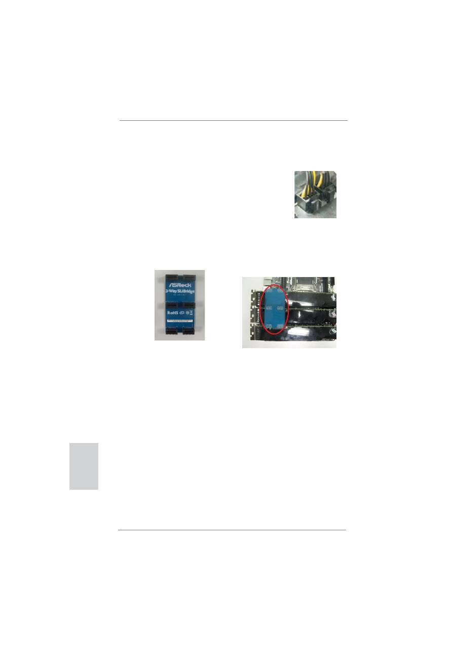
Step4. Connect a VGA cable or a DVI cable to the monitor connector or the DVI
connector of the graphics card that is inserted to PCIE1 slot.
Step3. Align and insert the ASRock 3-Way SLI Bridge Card to the goldfingers
on each graphics card. Make sure the ASRock 3-Way SLI Bridge Card is
fi
rmly in place.
ASRock 3-Way SLI Bridge Card
Step2. Connect the auxiliary power source to the PCI Express graphics card.
Please make sure that both power connectors on the PCI Express graph-
ics card are connected. Repeat this step on the three graphics cards.

27
ASRock Z77 Extreme9 Motherboard
English
2.7.1.3 Installing Four SLI
TM
-Ready Graphics Cards
Step 1. Install identical 4-Way SLI
TM
-ready graphics cards that are NVIDIA
®
certi-
fi
ed because different types of graphics cards will not work together prop-
erly. (Even the GPU chips version shall be the same.) Each graphics card
should have two gold
fi
ngers for the ASRock SLI Bridge Card connectors.
Insert one graphics card into the PCIE1 slot, another graphics card into the
PCIE3 slot, the third graphics card into the PCIE5 slot and the last graph-
ics card into the PCIE7 slot. Make sure that the cards are properly seated
on the slots.
Step2. Connect the auxiliary power source to the PCI Express graphics card.
Please make sure that both power connectors on the PCI Express graph-
ics card are connected. Repeat this step on the other graphics cards.
Step4. Connect a VGA cable or a DVI cable to the monitor connector or the DVI
connector of the graphics card that is inserted to PCIE1 slot.
Two Gold
fi
ngers
Step3. Align and insert an ASRock SLI Bridge Card to the gold
fi
ngers of the
fi
rst
and second graphics card. Install the second ASRock SLI Bridge Card to
the gold
fi
ngers of the third and fourth graphics card. Connect the second
and the fourth graphics card with the ASRock SLI_Bridge_3S Card. Make
sure the ASRock SLI Bridge Cards are
fi
rmly in place.
2 ASRock SLI_Bridge Cards
and an ASRock SLI_Bridge_3S Card
28
ASRock Z77 Extreme9 Motherboard
English
2.7.2 Driver Installation and Setup
Install the graphics card drivers to your system. After that, you can enable the Multi-
Graphics Processing Unit (GPU) feature in the NVIDIA
®
nView system tray utility.
Please follow the below procedures to enable the multi-GPU feature.
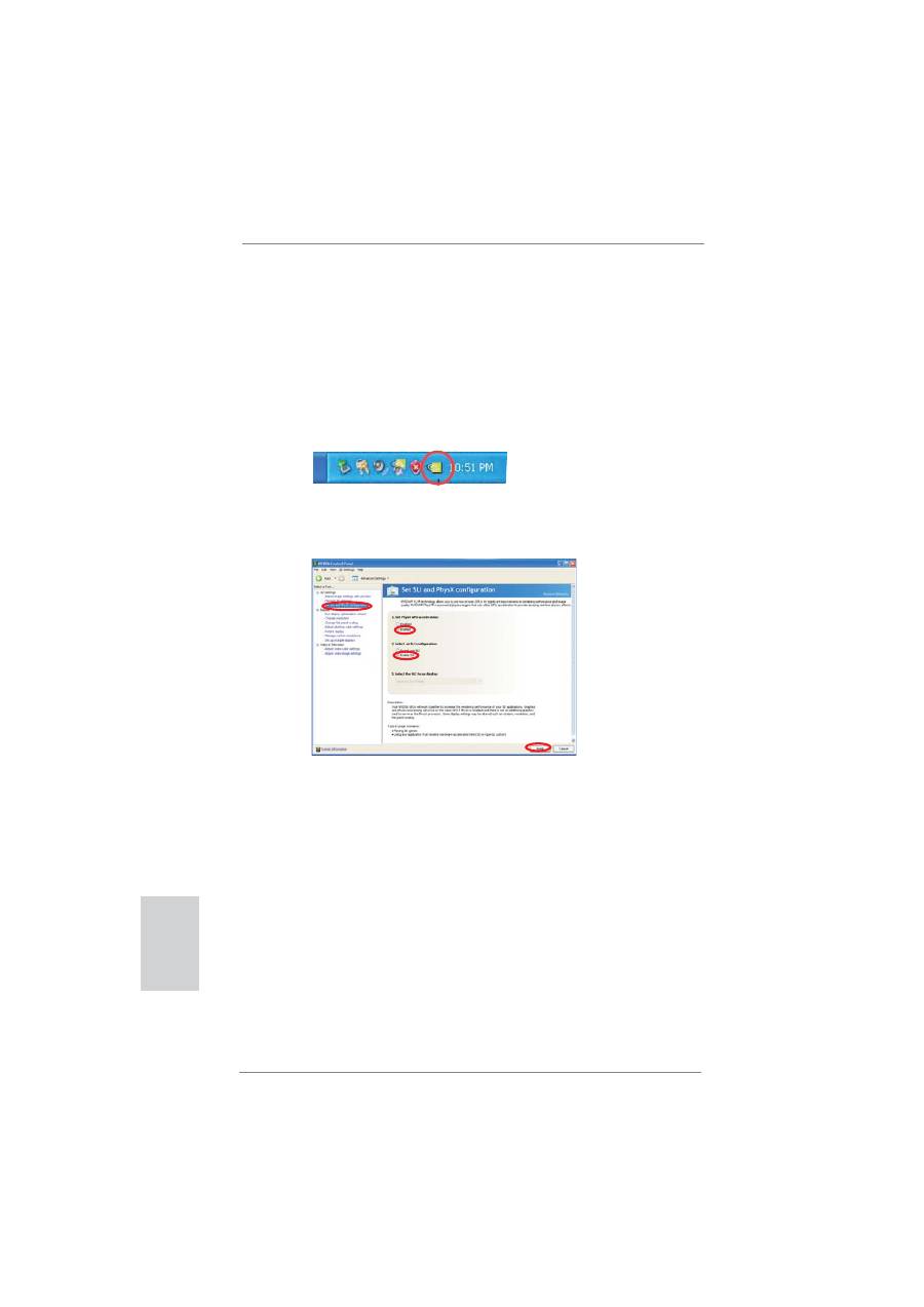
For Windows
®
XP / XP 64-bit OS:
(For
SLI
TM
mode only)
A.
Double-click
NVIDIA Settings icon
on your Windows
®
taskbar.
B. From the pop-up menu, select
Set SLI and PhysX con
fi
guration
. In
Set PhysX GPU acceleration
item, please select
Enabled
. In
Select
an SLI con
fi
guration
item, please select
Enable SLI
. And click
Apply
.
C. Reboot your system.
D. You can freely enjoy the bene
fi
t of SLI
TM
feature.
29
ASRock Z77 Extreme9 Motherboard
English
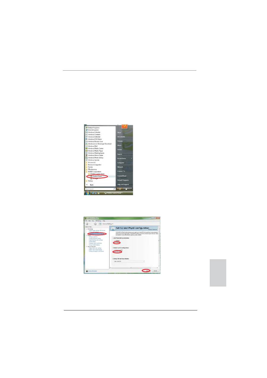
For
Windows
®
Vista
TM
/ Vista
TM
64-bit / 7 / 7 64-bit OS:
(For
SLI
TM
and Quad SLI
TM
mode)
A. Click the
Start
icon on your Windows taskbar.
B. From the pop-up menu, select
All Programs
, and then click
NVIDIA
Corporation
.
C.
Select
NVIDIA Control Panel
tab.
D.
Select
Control Panel
tab.
E. From the pop-up menu, select
Set SLI and PhysX con
fi
guration
. In
Set PhysX GPU acceleration
item, please select
Enabled
. In
Select
an SLI con
fi
guration
item, please select
Enable SLI
. And click
Apply
.
F. Reboot your system.
G. You can freely enjoy the bene
fi
t of SLI
TM
or Quad SLI
TM
feature.
30
ASRock Z77 Extreme9 Motherboard
English
* SLI
TM
appearing here is a registered trademark of NVIDIA
®
Technologies Inc., and is used
only for identi
fi
cation or explanation and to the owners’ bene
fi
t, without intent to infringe.
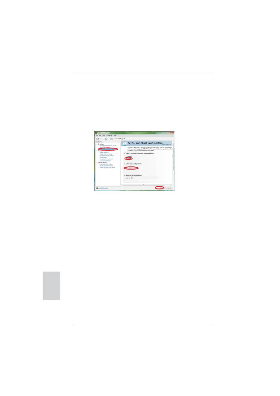
For
Windows
®
Vista
TM
/ Vista
TM
64-bit / 7 / 7 64-bit OS:
(For 3-Way SLI
TM
or 4-Way SLI
TM
mode)
A. Follow step A to D on page 28.
B. From the pop-up menu, select
Set SLI and PhysX con
fi
guration
. In
Select a hardware acceleration setting for PhysX
item, please
select
Enabled
. In
Select an SLI con
fi
guration
item, please select
Enable 3-way SLI
or
Enable 4-way SLI
. And click
Apply
.
C. Reboot your system.
D. You can freely enjoy the bene
fi
ts of 3-Way SLI
TM
or 4-Way SLI
TM
.
31
ASRock Z77 Extreme9 Motherboard
English
2.8 CrossFireX
TM
, 3-Way CrossFireX
TM
, 4-Way CrossFireX
TM
and
Quad CrossFireX
TM
Operation Guide
This motherboard supports CrossFireX
TM
, 3-way CrossFireX
TM
, 4-way CrossFireX
TM
and Quad CrossFireX
TM
. CrossFireX
TM
technology offers the most advantageous
means available of combining multiple high performance Graphics Processing
Units (GPU) in a single PC. Combining a range of different operating modes with
intelligent software design and an innovative interconnect mechanism, CrossFireX
TM
enables the highest possible level of performance and image quality in any 3D
application. Currently CrossFireX
TM
is supported with Windows
®
XP / Vista
TM
/ 7 OS.
3-way CrossFireX
TM
, 4-way CrossFireX
TM
and Quad CrossFireX
TM
are supported
with Windows
®
Vista
TM
/ 7 OS only. Please check AMD’s website for CrossFireX
TM
driver updates.
2.8.1 Graphics Card Setup
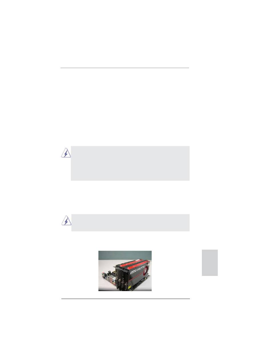
2.8.1.1 Installing Two CrossFireX
TM
-Ready Graphics Cards
Step 1. Insert one Radeon graphics card into PCIE1 slot and the other Radeon
graphics card to PCIE5 slot. Make sure that the cards are properly seated
on the slots.
Different CrossFireX
TM
cards may require different methods to enable CrossFireX
TM
feature. For other CrossFireX
TM
cards that AMD has released or will release in the
future, please refer to AMD graphics card manuals for detailed installation guide.
1. If a customer incorrectly con
fi
gures their system they will not see the performance
bene
fi
ts of CrossFireX
TM
. All three CrossFireX
TM
components, a CrossFireX
TM
Ready graphics card, a CrossFireX
TM
Ready motherboard and a CrossFireX
TM
Edition co-processor graphics card, must be installed correctly to bene
fi
t from the
CrossFireX
TM
multi-GPU platform.
2. If you pair a 12-pipe CrossFireX
TM
Edition card with a 16-pipe card, both cards
will operate as 12-pipe cards while in CrossFireX
TM
mode.
32
ASRock Z77 Extreme9 Motherboard
English
Step 3. Connect the DVI monitor cable to the DVI connector on the Radeon graph-
ics card on PCIE1 slot. (You may use the DVI to D-Sub adapter to convert
the DVI connector to D-Sub interface, and then connect the D-Sub monitor
cable to the DVI to D-Sub adapter.)
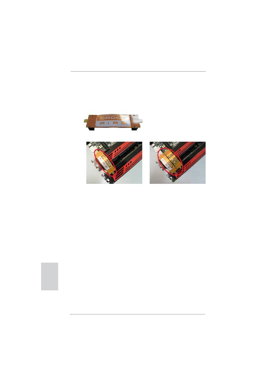
Step 2. Connect two Radeon graphics cards by installing a CrossFire Bridge on
the CrossFire Bridge Interconnects on the top of the Radeon graphics
cards. (The CrossFire Bridge is provided with the graphics card you pur-
chase, not bundled with this motherboard. Please refer to your graphics
card vendor for details.)
CrossFire Bridge
or
33
ASRock Z77 Extreme9 Motherboard
English
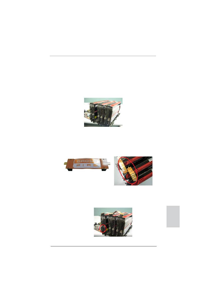
2.8.1.2 Installing Three CrossFireX
TM
-Ready Graphics Cards
Step 1. Install identical 3-Way CrossFireX
TM
-ready graphics cards that are AMD
®
certi
fi
ed because different types of graphics cards will not work together
properly. (Even the GPU chips version shall be the same.) Insert one
graphics card into PCIE1 slot, another graphics card to PCIE3 slot, and
the other graphics card to PCIE5 slot. Make sure that the cards are prop-
erly seated on the slots.
Step 2. Use one CrossFire
TM
Bridge to connect the Radeon graphics cards on
PCIE1 and PCIE3 slots, and use the other CrossFire
TM
Bridge to connect
the Radeon graphics cards on PCIE3 and PCIE5 slots. (The CrossFire
TM
Bridge is provided with the graphics card you purchase, not bundled with
this motherboard. Please refer to your graphics card vendor for details.)
Step 3. Connect the DVI monitor cable to the DVI connector on the Radeon graph-
ics card on PCIE1 slot. (You may use the DVI to D-Sub adapter to convert
the DVI connector to D-Sub interface, and then connect the D-Sub monitor
cable to the DVI to D-Sub adapter.)
CrossFire
TM
Bridge
34
ASRock Z77 Extreme9 Motherboard
English
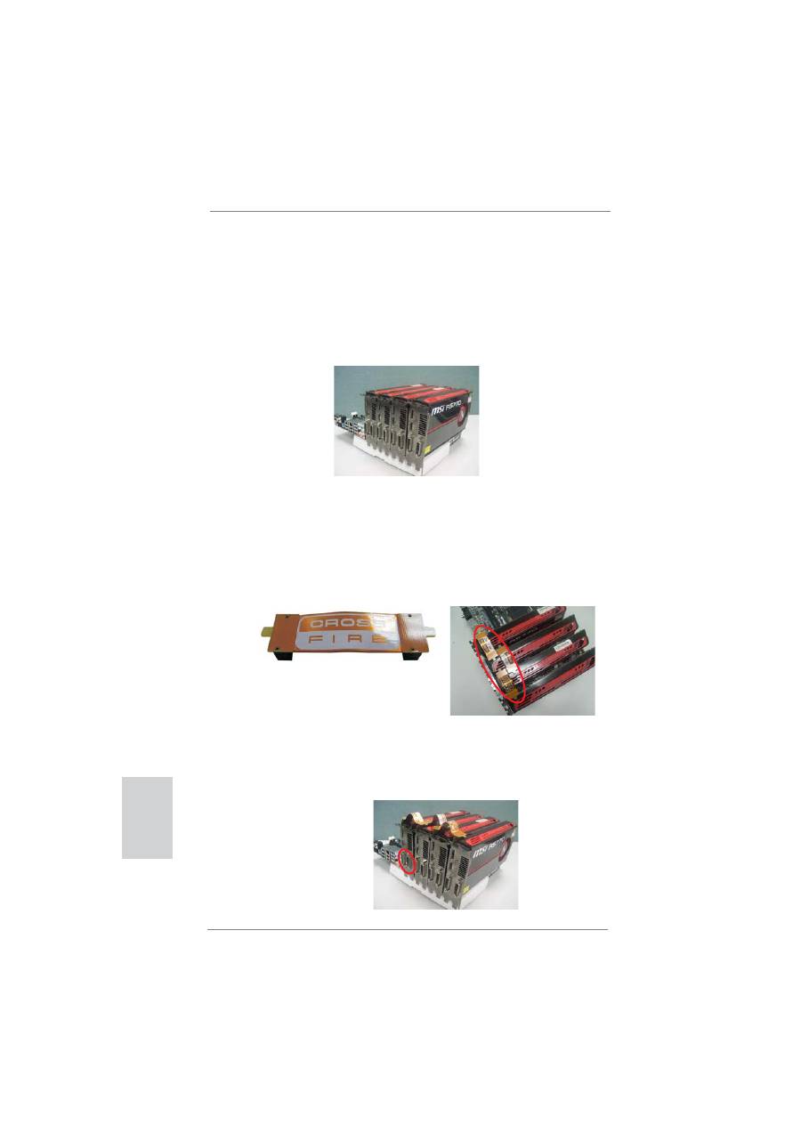
2.8.1.3 Installing Four CrossFireX
TM
-Ready Graphics Cards
Step 1. Install identical 4-Way CrossFireX
TM
-ready graphics cards that are AMD
®
certi
fi
ed because different types of graphics cards will not work together
properly. (Even the GPU chips version shall be the same.) Insert one
graphics card into PCIE1 slot, another graphics card into PCIE3 slot, the
third graphics card into PCIE5 slot and the last graphics card into PCIE7
slot. Make sure that the cards are properly seated on the slots.
Step 2. Use one CrossFire
TM
Bridge to connect the Radeon graphics cards on
PCIE1 and PCIE3 slots, another CrossFire
TM
Bridge to connect the Rad-
eon graphics cards on PCIE3 and PCIE5 slots, and use the third Cross-
Fire
TM
Bridge to connect the Radeon graphics cards on PCIE5 and PCIE7
slots. (The CrossFire
TM
Bridge is provided with the graphics card you pur-
chase, not bundled with this motherboard. Please refer to your graphics
card vendor for details.)
CrossFire
TM
Bridge
Step 3. Connect the DVI monitor cable to the DVI connector on the Radeon graph-
ics card on PCIE1 slot. (You may use the DVI to D-Sub adapter to convert
the DVI connector to D-Sub interface, and then connect the D-Sub monitor
cable to the DVI to D-Sub adapter.)

35
ASRock Z77 Extreme9 Motherboard
English
The Catalyst Uninstaller is an optional download. We recommend using this
utility to uninstall any previously installed Catalyst drivers prior to installation.
Please check AMD website for ATI
TM
driver updates.
Step 3. Install the required drivers to your system.
For Windows
®
XP OS:
A. AMD recommends Windows
®
XP Service Pack 2 or higher to be
installed (If you have Windows
®
XP Service Pack 2 or higher installed
in your system, there is no need to download it again):
http://www.microsoft.com/windowsxp/sp2/default.mspx
B. You must have Microsoft .NET Framework installed prior to
downloading and installing the CATALYST Control Center. Please
check Microsoft website for details.
For
Windows
®
7 / Vista
TM
OS:
Install the CATALYST Control Center. Please check AMD website for de-
tails.
Step 4. Restart your computer.
Step 5. Install the VGA card drivers to your system, and restart your computer.
Then you will
fi
nd “ATI Catalyst Control Center” on your Windows
®
taskbar.
ATI Catalyst Control Center
2.8.2 Driver Installation and Setup
Step 1. Power on your computer and boot into OS.
Step 2. Remove the AMD driver if you have any VGA driver installed in your
system.

36
ASRock Z77 Extreme9 Motherboard
English
Although you have selected the option “Enable CrossFire
TM
”, the CrossFireX
TM
function may not work actually. Your computer will automatically reboot. After
restarting your computer, please con
fi
rm whether the option “Enable
CrossFire
TM
” in “ATI Catalyst Control Center” is selected or not; if not, please
select it again, and then you are able to enjoy the bene
fi
t of CrossFireX
TM
feature.
Step 7. You can freely enjoy the benefit of CrossFireX
TM
, 3-Way CrossFireX
TM
,
4-Way CrossFireX
TM
or Quad CrossFireX
TM
feature.
* CrossFireX
TM
appearing here is a registered trademark of AMD Technologies Inc., and is
used only for identi
fi
cation or explanation and to the owners’ bene
fi
t, without intent to infringe.
* For further information of AMD CrossFireX
TM
technology, please check AMD website for
updates and details.
Step 6. Double-click “ATI Catalyst Control Center”. Click “View”, select “CrossFi-
reX
TM
”, and then check the item “Enable CrossFireX
TM
”. Select “2 GPUs”
and click “Apply” (if you install two Radeon graphics cards). Select “3
GPUs” and click “OK” (if you install three Radeon graphics cards). Select “4
GPUs” and click “OK” (if you install four Radeon graphics cards).
37
ASRock Z77 Extreme9 Motherboard
English
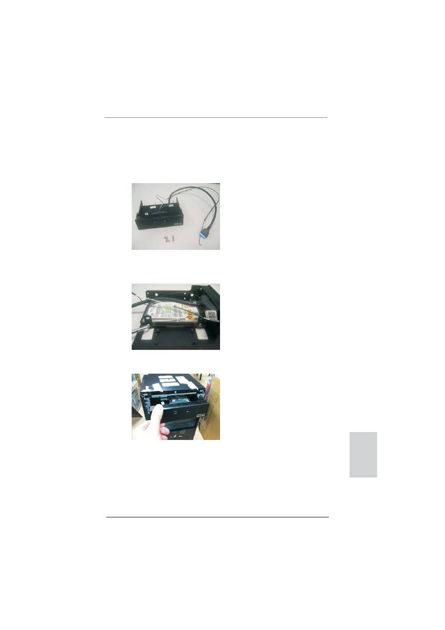
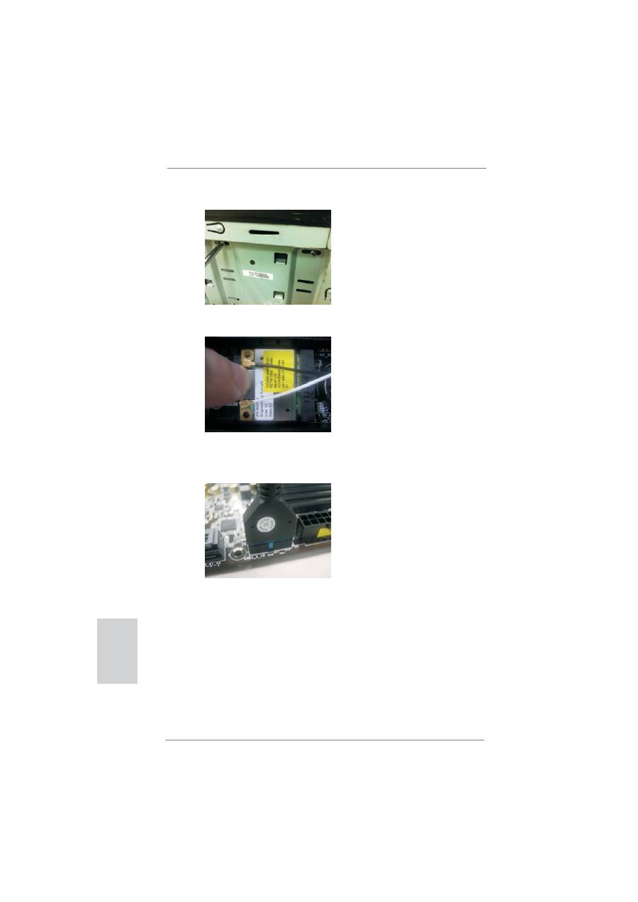
2.9 WiFi + BT Module and ASRock Wi-SB Box Installation Guide
This motherboard is bundled with one WiFi + BT module and one ASRock Wi-SB
Box. Please follow below procedures to properly install them.
Step 1. Prepare the bundled ASRock Wi-SB Box and screws.
Step 2. If you have 2.5” HDD/SSDs, you may insert up to two and secure them in
ASRock Wi-SB Box with screws.
Step 3. Install ASRock Wi-SB Box into the drive bay of the chassis.
38
ASRock Z77 Extreme9 Motherboard
English
Step 4. Screw ASRock Wi-SB Box to the drive bay with screws.
Step 5. Attach the cords to the WiFi + BT module on your motherboard.
Step 6. Plug the Front USB 3.0 cable into the USB 3.0 header (USB3_9_10 or
USB3_11_12) on the motherboard.
39
ASRock Z77 Extreme9 Motherboard
English
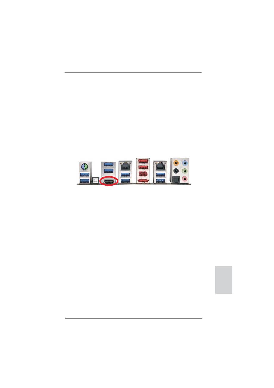
2.10 Surround Display Feature
This motherboard supports surround display upgrade. With the internal HDMI output
support and external add-on PCI Express VGA cards, you can easily enjoy the ben-
e
fi
ts of surround display feature.
Please refer to the following steps to set up a surround display environment:
1. Install the PCI Express VGA cards on PCIE1, PCIE2, PCIE3, PCIE4, PCIE5 and
PCIE7 slots. Please refer to page 22 for proper expansion card installation
procedures.
2. Connect a HDMI monitor cable to the HDMI port on the I/O panel. Then connect
other monitor cables to the corresponding connectors of the add-on PCI Express
VGA cards on PCIE1, PCIE2, PCIE3, PCIE4, PCIE5 and PCIE7 slots.
3. Boot your system. Press <F2> or <Del> to enter UEFI setup. Enter “Share
Memory” option to adjust the memory capability to [32MB], [64MB], [128MB],
[256MB] or [512MB] to enable the function of HDMI. Please make sure that the
value you select is less than the total capability of the system memory. If you do
not adjust the UEFI setup, the default value of “Share Memory”, [Auto], will
disable HDMI function when an add-on VGA card is inserted to this motherboard.
4. Install the onboard VGA driver and the add-on PCI Express VGA card driver to
your system. If you have installed the drivers already, there is no need to install
them again.
5. Set up a multi-monitor display.
For Windows
®
XP / XP 64-bit OS:
Right click on desktop, choose “Properties”, and select the “Settings” tab
so that you can adjust the parameters of the multi-monitors according to
the steps below.
A. Click the “Identify” button to display a large number on each monitor.
B. Right-click the display icon in the Display Properties dialog that you
wish to be your primary monitor, and then select “Primary”. When
you use multiple monitors with your card, one monitor will always be
Primary, and all additional monitors will be designated as Secondary.
HDMI port

40
ASRock Z77 Extreme9 Motherboard
C. Select the display icon identi
fi
ed by the number 2.
D. Click “Extend my Windows desktop onto this monitor”.
E. Right-click the display icon and select “Attached”, if necessary.
F. Set the appropriate “Screen Resolution” and “Color Quality” for the
second monitor. Click “Apply” or “OK” to apply these new values.
G. Repeat steps C through E for the display icon identi
fi
ed by the
numbers three to thirteen.
For Windows
®
7 / 7 64-bit / Vista
TM
/ Vista
TM
64-bit OS:
Right click the desktop, choose “Personalize”, and select the “Display
Settings” tab so that you can adjust the parameters of the multi-monitors
according to the steps below.
A. Click the number ”2” icon.
B. Click the items “This is my main monitor” and “Extend the desktop onto
this monitor”.
C. Click “OK” to save your change.
D. Repeat steps A through C for the display icons identi
fi
ed by the number
three to thirteen.
6. Use Surround Display. Click and drag the display icons to positions representing
the physical setup of your monitors that you would like to use. The placement of
display icons determines how you move items from one monitor to another.
English
