ASRock Z68 Extreme7 Gen3 – страница 2
Инструкция к Материнской Плате ASRock Z68 Extreme7 Gen3
21
ASRock Z68 Extreme7 Gen3 Motherboard
English
Step4. Connect a VGA cable or a DVI cable to the monitor connector or the DVI
connector of the graphics card that is inserted to PCIE1 slot.
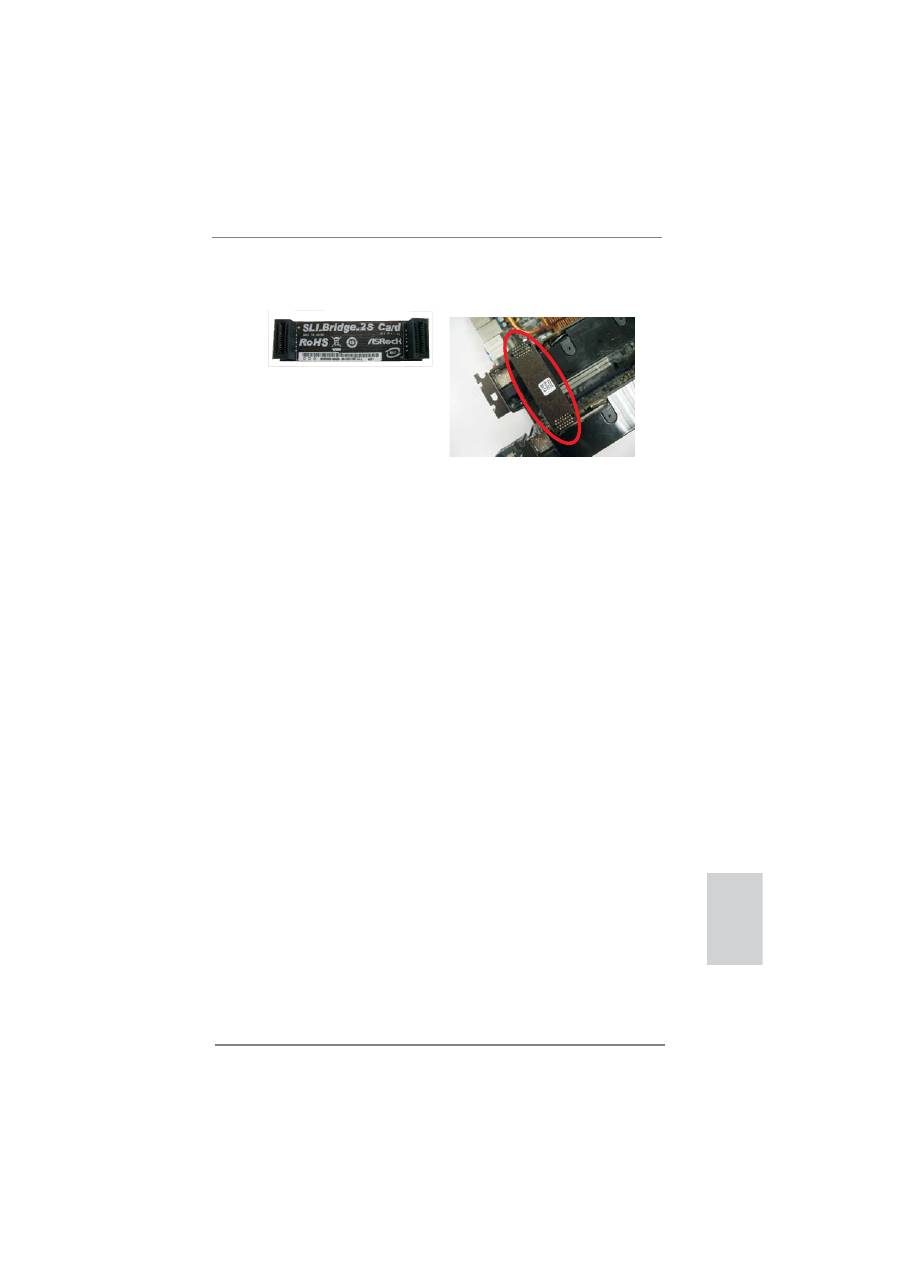
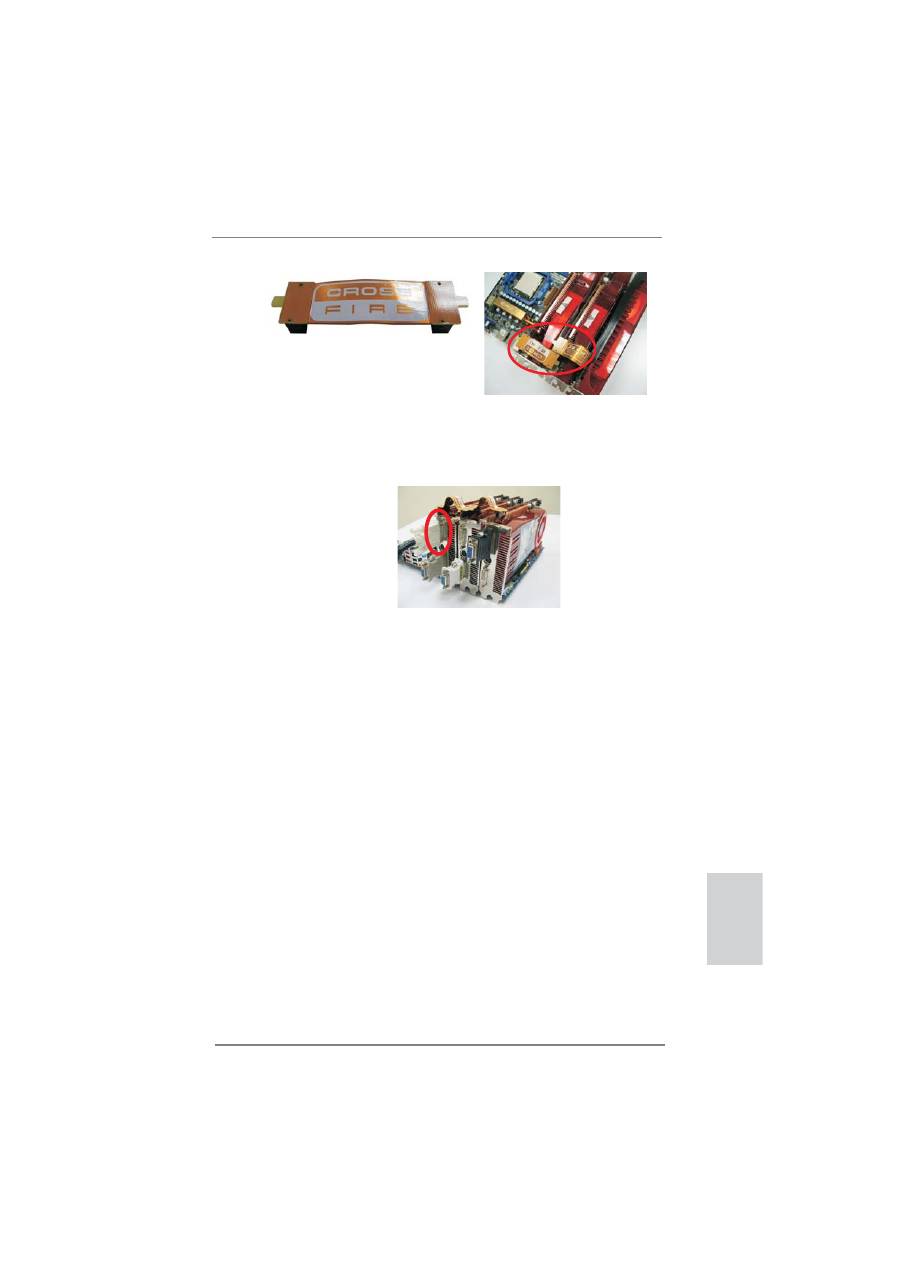
Step3. Align and insert ASRock SLI_Bridge_2S Card to the gold
fi
ngers on each
graphics card. Make sure ASRock SLI_Bridge_2S Card is
fi
rmly in place.
ASRock SLI_Bridge_2S Card
22
ASRock Z68 Extreme7 Gen3 Motherboard
English
2.5.1.2 Installing Three SLI
TM
-Ready Graphics Cards
Step 1. Install the identical 3-Way SLI
TM
-ready graphics cards that are NVIDIA
®
certi
fi
ed because different types of graphics cards will not work together
properly. (Even the GPU chips version shall be the same.) Each graph-
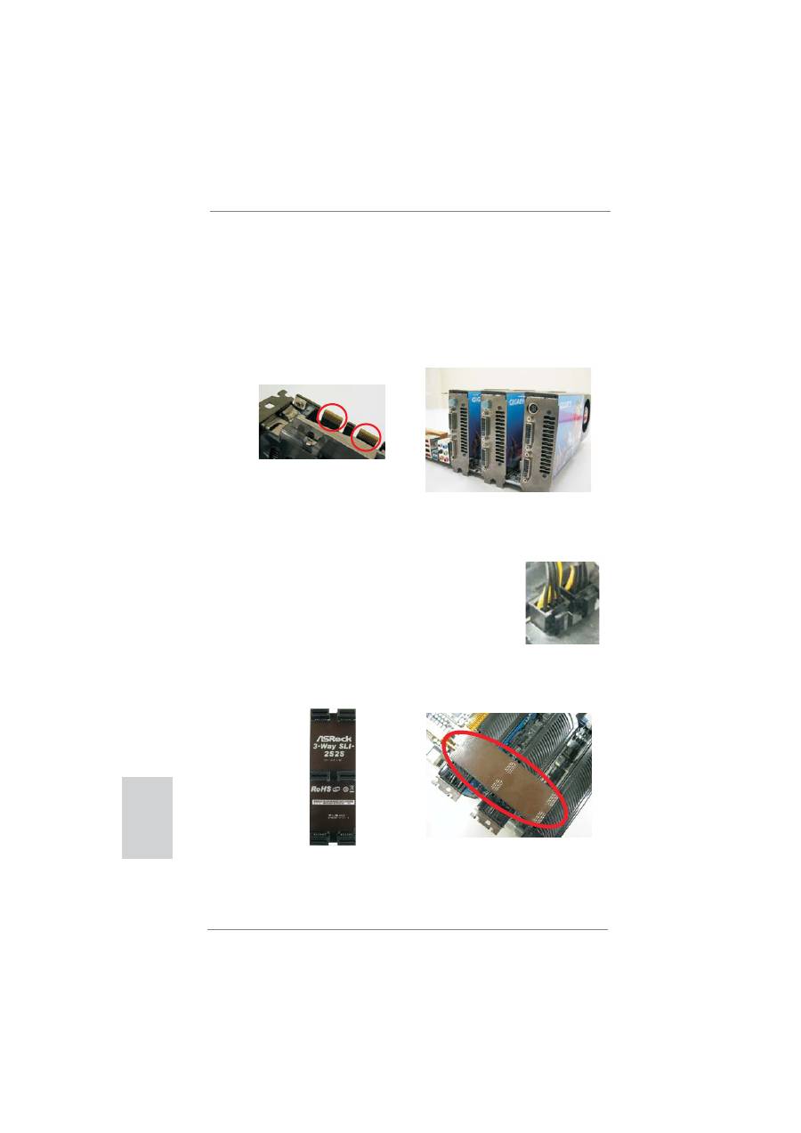
ics card should have two gold
fi
ngers for the 3-Way SLI Bridge connector.
Insert one graphics card into PCIE1 slot, another graphics card to PCIE4
slot, and the other graphics card to PCIE6 slot. Make sure that the cards
are properly seated on the slots.
Step2. Connect the auxiliary power source to the PCI Express graphics card.
Please make sure that both power connectors on the PCI Express graph-
ics card are connected. Repeat this step on the three graphics cards.
Step4. Connect a VGA cable or a DVI cable to the monitor connector or the DVI
connector of the graphics card that is inserted to PCIE1 slot.
Two Gold
fi
ngers
Step3. Align and insert ASRock 3-Way SLI-2S2S Bridge Card to the gold
fi
ngers
on each graphics card. Make sure ASRock 3-Way SLI-2S2S Bridge Card
is
fi
rmly in place.
ASRock 3-Way SLI-2S2S Bridge Card
23
ASRock Z68 Extreme7 Gen3 Motherboard
English
2.5.2 Driver Installation and Setup
Install the graphics card drivers to your system. After that, you can enable the Multi-
Graphics Processing Unit (GPU) feature in the NVIDIA
®
nView system tray utility.
Please follow the below procedures to enable the multi-GPU feature.
For Windows
®
XP / XP 64-bit OS:
(For
SLI
TM
mode only)
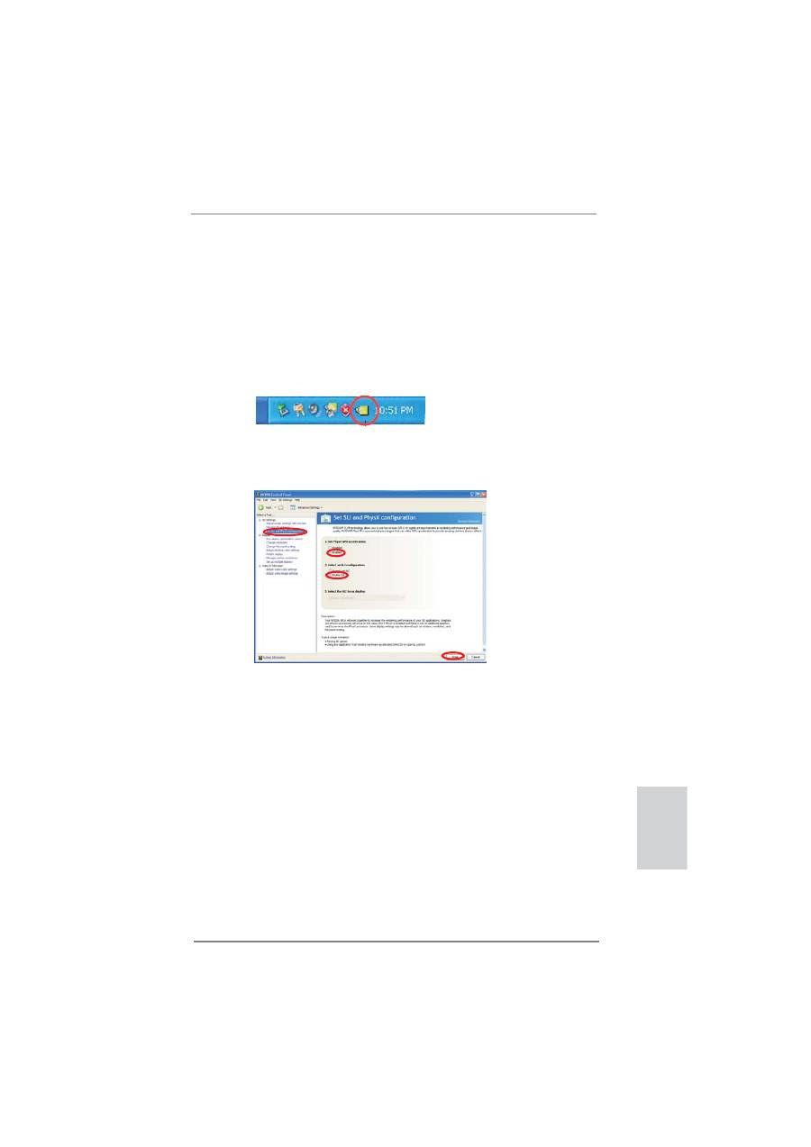
A.
Double-click
NVIDIA Settings icon
on your Windows
®
taskbar.
B. From the pop-up menu, select
Set SLI and PhysX con
fi
guration
. In
Set PhysX GPU acceleration
item, please select
Enabled
. In
Select
an SLI con
fi
guration
item, please select
Enable SLI
. And click
Apply
.
C. Reboot your system.
D. You can freely enjoy the bene
fi
t of SLI
TM
feature.
24
ASRock Z68 Extreme7 Gen3 Motherboard
English
For
Windows
®
Vista
TM
/ Vista
TM
64-bit / 7 / 7 64-bit OS:
(For
SLI
TM
and Quad SLI
TM
mode)
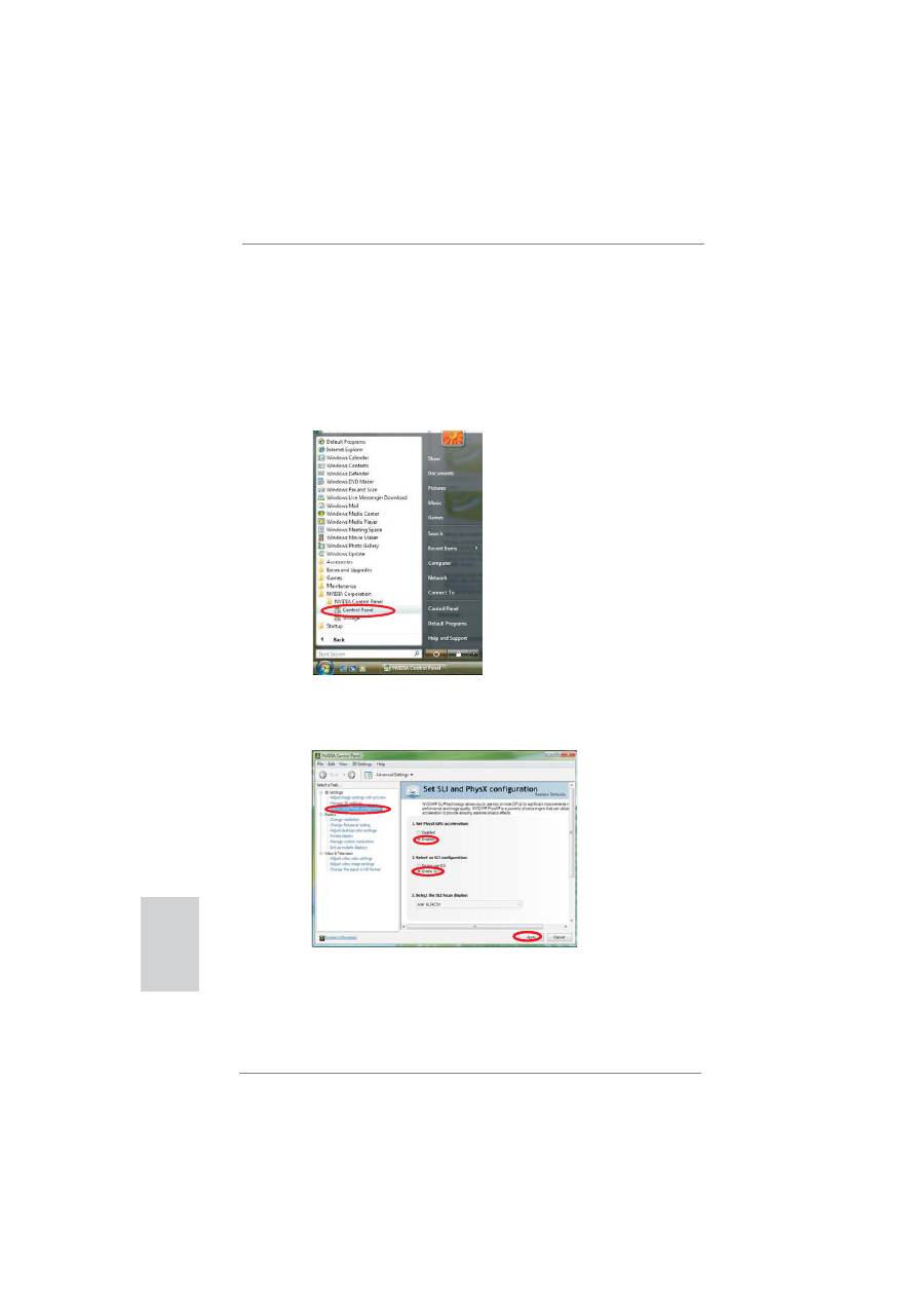
A. Click the
Start
icon on your Windows taskbar.
B. From the pop-up menu, select
All Programs
, and then click
NVIDIA
Corporation
.
C.
Select
NVIDIA Control Panel
tab.
D.
Select
Control Panel
tab.
E. From the pop-up menu, select
Set SLI and PhysX con
fi
guration
. In
Set PhysX GPU acceleration
item, please select
Enabled
. In
Select
an SLI con
fi
guration
item, please select
Enable SLI
. And click
Apply
.
F. Reboot your system.
G. You can freely enjoy the bene
fi
t of SLI
TM
or Quad SLI
TM
feature.
25
ASRock Z68 Extreme7 Gen3 Motherboard
English
* SLI
TM
appearing here is a registered trademark of NVIDIA
®
Technologies Inc., and is used
only for identi
fi
cation or explanation and to the owners’ bene
fi
t, without intent to infringe.
For
Windows
®
Vista
TM
/ Vista
TM
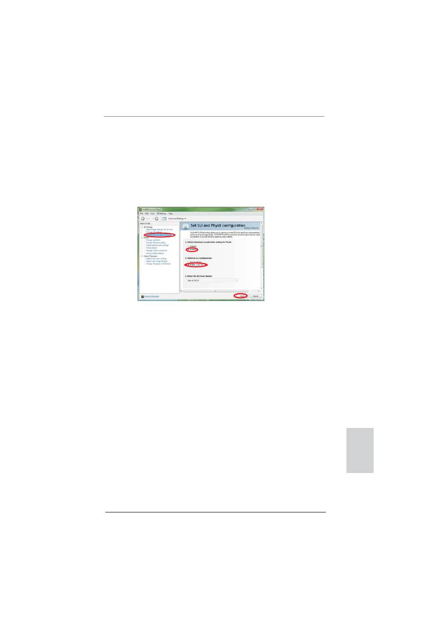
64-bit / 7 / 7 64-bit OS:
(For 3-Way SLI
TM
mode)
A. Follow step A to D on page 23.
B. From the pop-up menu, select
Set SLI and PhysX con
fi
guration
. In
Select a hardware acceleration setting for PhysX
item, please
select
Enabled
. In
Select an SLI con
fi
guration
item, please select
Enable 3-way SLI
. And click
Apply
.
C. Reboot your system.
D. You can freely enjoy the bene
fi
t of 3-Way SLI
TM
feature.
26
ASRock Z68 Extreme7 Gen3 Motherboard
English
1. If a customer incorrectly con
fi
gures their system they will not see the
performance bene
fi
ts of CrossFireX
TM
. All three CrossFireX
TM
components, a
CrossFireX
TM
Ready graphics card, a CrossFireX
TM
Ready motherboard and a
CrossFireX
TM
Edition co-processor graphics card, must be installed correctly to
bene
fi
t from the CrossFireX
TM
multi-GPU platform.
2. If you pair a 12-pipe CrossFireX
TM
Edition card with a 16-pipe card, both cards
will operate as 12-pipe cards while in CrossFireX
TM
mode.
2.6
CrossFireX
TM
, 3-Way CrossFireX
TM
and Quad
CrossFireX
TM
Operation Guide
This motherboard supports CrossFireX
TM
, 3-way CrossFireX
TM
and Quad
CrossFireX
TM
feature. CrossFireX
TM
technology offers the most advantageous
means available of combining multiple high performance Graphics Processing
Units (GPU) in a single PC. Combining a range of different operating modes with
intelligent software design and an innovative interconnect mechanism, CrossFireX
TM
enables the highest possible level of performance and image quality in any 3D
application. Currently CrossFireX
TM
feature is supported with Windows
®
XP with
Service Pack 2 / Vista
TM
/ 7 OS. 3-way CrossFireX
TM
and Quad CrossFireX
TM
feature
are supported with Windows
®
Vista
TM
/ 7 OS only. Please check AMD website for
ATI
TM
CrossFireX
TM
driver updates.
2.6.1 Graphics Card Setup
2.6.1.1 Installing Two CrossFireX
TM
-Ready Graphics Cards
Different CrossFireX
TM
cards may require different methods to enable CrossFireX
TM
feature. In below procedures, we use Radeon HD 3870 as the example graphics
card. For other CrossFireX
TM
cards that AMD has released or will release in the
future, please refer to AMD graphics card manuals for detailed installation guide.
Step 1. Insert one Radeon graphics card into PCIE1 slot and the other Radeon
graphics card to PCIE4 slot. Make sure that the cards are properly seated
on the slots.
27
ASRock Z68 Extreme7 Gen3 Motherboard
English
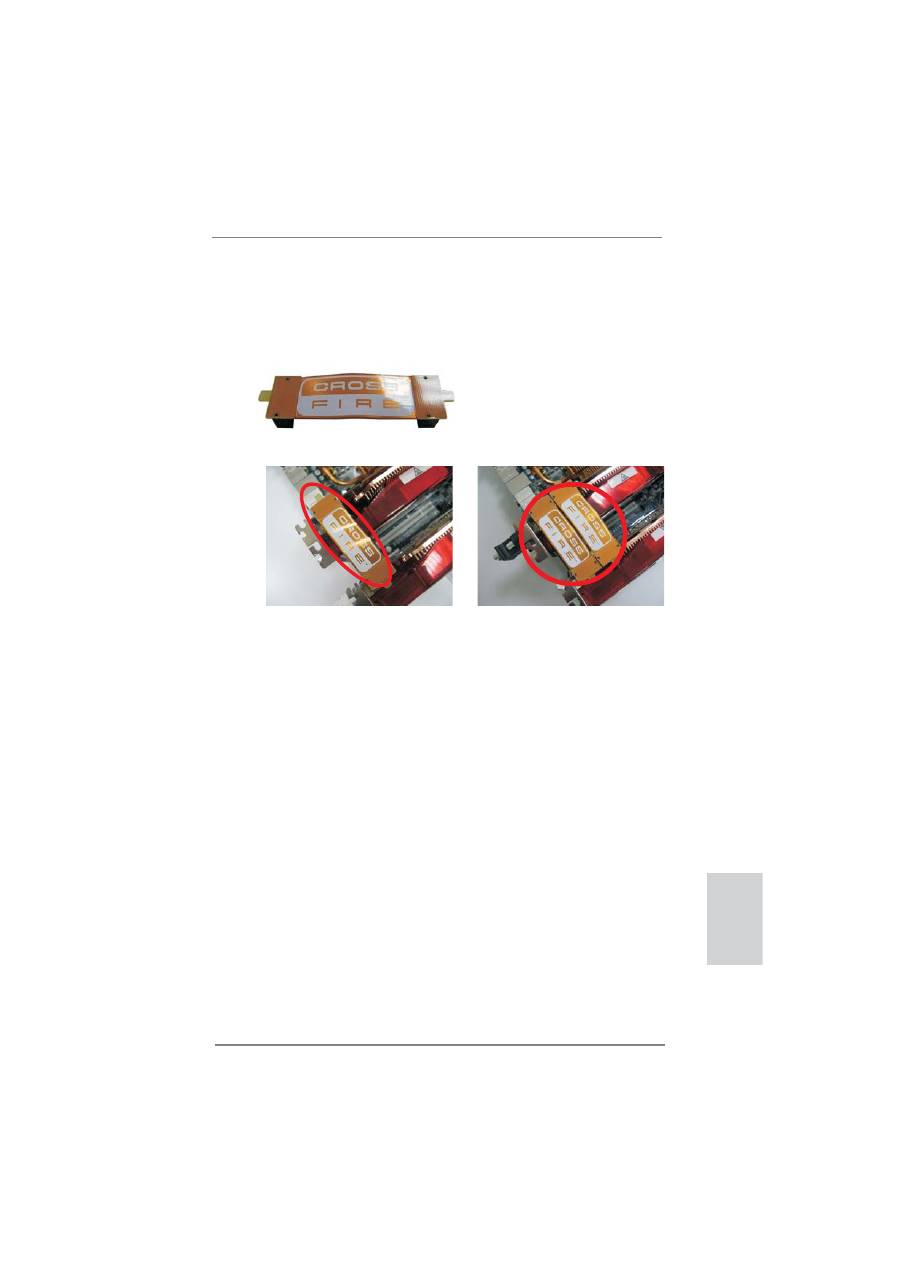
CrossFire Bridge
Step 3. Connect the DVI monitor cable to the DVI connector on the Radeon
graphics card on PCIE1 slot. (You may use the DVI to D-Sub adapter to
convert the DVI connector to D-Sub interface, and then connect the D-Sub
monitor cable to the DVI to D-Sub adapter.)
Step 2. Connect two Radeon graphics cards by installing CrossFire Bridge on
CrossFire Bridge Interconnects on the top of Radeon graphics cards.
(CrossFire Bridge is provided with the graphics card you purchase, not
bundled with this motherboard. Please refer to your graphics card vendor
for details.)
or
28
ASRock Z68 Extreme7 Gen3 Motherboard
English
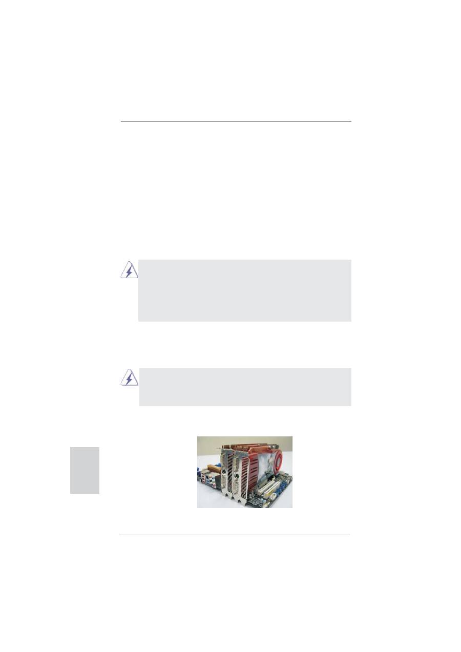
2.6.1.2 Installing Three CrossFireX
TM
-Ready Graphics Cards
Step 1. Install one Radeon graphics card to PCIE1 slot. For the proper installation
procedures, please refer to section “Expansion Slots”.
Step 2. Install one Radeon graphics card to PCIE4 slot. For the proper installation
procedures, please refer to section “Expansion Slots”.
Step 3. Install one Radeon graphics card to PCIE6 slot. For the proper installation
procedures, please refer to section “Expansion Slots”.
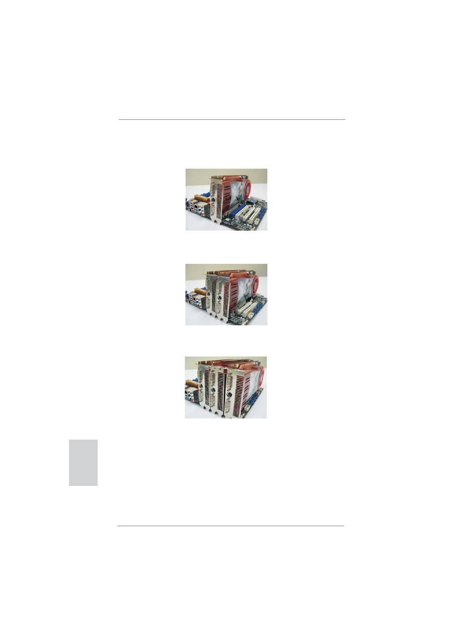
Step 4. Use one CrossFire
TM
Bridge to connect Radeon graphics cards on PCIE1
and PCIE4 slots, and use the other CrossFire
TM
Bridge to connect Radeon
graphics cards on PCIE4 and PCIE6 slots. (CrossFire
TM
Bridge is provided
with the graphics card you purchase, not bundled with this motherboard.
Please refer to your graphics card vendor for details.)
29
ASRock Z68 Extreme7 Gen3 Motherboard
English
CrossFire
TM
Bridge
Step 5. Connect the DVI monitor cable to the DVI connector on the Radeon graph-
ics card on PCIE1 slot. (You may use the DVI to D-Sub adapter to convert
the DVI connector to D-Sub interface, and then connect the D-Sub monitor
cable to the DVI to D-Sub adapter.)
30
ASRock Z68 Extreme7 Gen3 Motherboard
English
The Catalyst Uninstaller is an optional download. We recommend using this
utility to uninstall any previously installed Catalyst drivers prior to installation.
Please check AMD website for ATI
TM
driver updates.
Step 3. Install the required drivers to your system.
For Windows
®
XP OS:
A. AMD recommends Windows
®
XP Service Pack 2 or higher to be
installed (If you have Windows
®
XP Service Pack 2 or higher installed
in your system, there is no need to download it again):
http://www.microsoft.com/windowsxp/sp2/default.mspx
B. You must have Microsoft .NET Framework installed prior to
downloading and installing the CATALYST Control Center. Please
check Microsoft website for details.
For
Windows
®
7 / Vista
TM
OS:
Install the CATALYST Control Center. Please check AMD website for de-
tails.
Step 4. Restart your computer.
Step 5. Install the VGA card drivers to your system, and restart your computer.
Then you will
fi
nd “ATI Catalyst Control Center” on your Windows
®
taskbar.
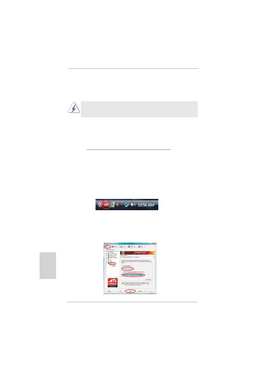
ATI Catalyst Control Center
2.6.2 Driver Installation and Setup
Step 1. Power on your computer and boot into OS.
Step 2. Remove the AMD driver if you have any VGA driver installed in your
system.
Step 6. Double-click “ATI Catalyst Control Center”. Click “View”, select “CrossFi-
reX
TM
”, and then check the item “Enable CrossFireX
TM
”. Select “2 GPUs”
and click “Apply” (if you install two Radeon graphics cards). Select “3
GPUs” and click “OK” (if you install three Radeon graphics cards).

31
ASRock Z68 Extreme7 Gen3 Motherboard
English
Although you have selected the option “Enable CrossFire
TM
”, the CrossFireX
TM
function may not work actually. Your computer will automatically reboot. After
restarting your computer, please con
fi
rm whether the option “Enable
CrossFire
TM
” in “ATI Catalyst Control Center” is selected or not; if not, please
select it again, and then you are able to enjoy the bene
fi
t of CrossFireX
TM
feature.
Step 7. You can freely enjoy the bene
fi
t of CrossFireX
TM
, 3-Way CrossFireX
TM
or
Quad CrossFireX
TM
feature.
* CrossFireX
TM
appearing here is a registered trademark of AMD Technologies Inc., and is
used only for identi
fi
cation or explanation and to the owners’ bene
fi
t, without intent to infringe.
* For further information of AMD CrossFireX
TM
technology, please check AMD website for
updates and details.
32
ASRock Z68 Extreme7 Gen3 Motherboard
English
2. If you have installed onboard VGA driver from our support CD to your system
already, you can freely enjoy the bene
fi
ts of dual monitor function after your
system boots. If you haven’t installed onboard VGA driver yet, please install
onboard VGA driver from our support CD to your system and restart your
computer.
2.7 Dual Monitor and Surround Display Features
Dual Monitor Feature
This motherboard supports dual monitor feature. With the internal VGA output sup-
port (DVI-D, D-Sub, HDMI and DisplayPort), you can easily enjoy the bene
fi
ts of
dual monitor feature without installing any add-on VGA card to this motherboard.
This motherboard also provides independent display controllers for DVI-D, D-Sub,
HDMI and DisplayPort to support dual VGA output so that DVI-D, D-sub, HDMI and
DisplayPort can drive same or different display contents.
To enable dual monitor feature, please follow the below steps:
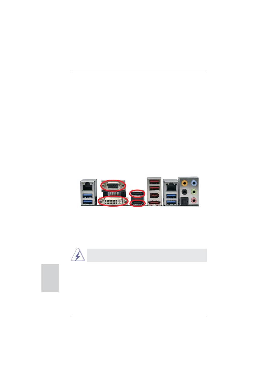
1. Connect DVI-D monitor cable to DVI-D port on the I/O panel, connect D-Sub
monitor cable to D-Sub port on the I/O panel, connect HDMI monitor cable to
HDMI port on the I/O panel, or connect DisplayPort monitor cable to DisplayPort
on the I/O panel.
D-Sub, DVI-D, HDMI and DisplayPort monitors cannot be enabled at the
same time. You can only choose two of them.
HDMI port
D-Sub port
DVI-D port
DisplayPort

33
ASRock Z68 Extreme7 Gen3 Motherboard
English
Surround Display Feature
This motherboard supports surround display upgrade. With the internal VGA output
support (DVI-D, D-Sub, HDMI and DisplayPort) and external add-on PCI Express
VGA cards, you can easily enjoy the bene
fi
ts of surround display feature.
Please refer to the following steps to set up a surround display environment:
1. Install the PCI Express VGA cards on PCIE1, PCIE4, PCIE5 and PCIE6 slots.
Please refer to page 18 for proper expansion card installation procedures for
details.
2. Connect DVI-D monitor cable to DVI-D port on the I/O panel, connect D-Sub
monitor cable to D-Sub port on the I/O panel, connect HDMI monitor cable
to HDMI port on the I/O panel, or connect DisplayPort monitor cable to
DisplayPort on the I/O panel. Then connect other monitor cables to the
corresponding connectors of the add-on PCI Express VGA cards on PCIE1,
PCIE4, PCIE5 and PCIE6 slots.
3. Boot your system. Press <F2> or <Del> to enter UEFI setup. Enter “Onboard
VGA Share Memory” option to adjust the memory capability to [32MB], [64MB],
[128MB], [256MB] or [512MB] to enable the function of D-sub. Please make
sure that the value you select is less than the total capability of the system
memory. If you do not adjust the UEFI setup, the default value of “Onboard VGA
Share Memory”, [Auto], will disable D-Sub function when the add-on VGA card is
inserted to this motherboard.
4. Install the onboard VGA driver and the add-on PCI Express VGA card driver to
your system. If you have installed the drivers already, there is no need to install
them again.
5. Set up a multi-monitor display.
For Windows
®
XP / XP 64-bit OS:
Right click the desktop, choose “Properties”, and select the “Settings” tab
so that you can adjust the parameters of the multi-monitor according to
the steps below.
A. Click the “Identify” button to display a large number on each monitor.
B. Right-click the display icon in the Display Properties dialog that you
wish to be your primary monitor, and then select “Primary”. When
you use multiple monitors with your card, one monitor will always be
Primary, and all additional monitors will be designated as Secondary.
C. Select the display icon identi
fi
ed by the number 2.
D. Click “Extend my Windows desktop onto this monitor”.
E. Right-click the display icon and select “Attached”, if necessary.
F. Set the “Screen Resolution” and “Color Quality” as appropriate for the
second monitor. Click “Apply” or “OK” to apply these new values.

34
ASRock Z68 Extreme7 Gen3 Motherboard
English
G. Repeat steps C through E for the diaplay icon identi
fi
ed by the number
one to ten.
For Windows
®
7 / 7 64-bit / Vista
TM
/ Vista
TM
64-bit OS:
Right click the desktop, choose “Personalize”, and select the “Display
Settings” tab so that you can adjust the parameters of the multi-monitor
according to the steps below.
A. Click the number ”2” icon.
B. Click the items “This is my main monitor” and “Extend the desktop onto
this monitor”.
C. Click “OK” to save your change.
D. Repeat steps A through C for the display icon identi
fi
ed by the number
three to ten.
6. Use Surround Display. Click and drag the display icons to positions representing
the physical setup of your monitors that you would like to use. The placement
of display icons determines how you move items from one monitor to another.
HDCP Function
HDCP function is supported on this motherboard. To use HDCP
function with this motherboard, you need to adopt the monitor
that supports HDCP function as well. Therefore, you can enjoy
the superior display quality with high-de
fi
nition HDCP
encryption contents. Please refer to below instruction for more
details about HDCP function.
What
is
HDCP?
HDCP stands for High-Bandwidth Digital Content Protection,
a
speci
fi
cation developed by Intel
®
for protecting digital
entertainment content that uses the DVI interface. HDCP is a
copy protection scheme to eliminate the possibility of
intercepting digital data midstream between the video source,
or transmitter - such as a computer, DVD player or set-top box -
and the digital display, or receiver - such as a monitor, television
or projector. In other words, HDCP speci
fi
cation is designed to
protect the integrity of content as it is being transmitted.
Products compatible with the HDCP scheme such as DVD
players, satellite and cable HDTV set-top-boxes, as well as few
entertainment PCs requires a secure connection to a compliant
display. Due to the increase in manufacturers employing HDCP
in their equipment, it is highly recommended that the HDTV or
LCD monitor you purchase is compatible.
35
ASRock Z68 Extreme7 Gen3 Motherboard
English
* ASRock Smart Remote is only supported by some of ASRock motherboards. Please refer to
ASRock website for the motherboard support list: http://www.asrock.com
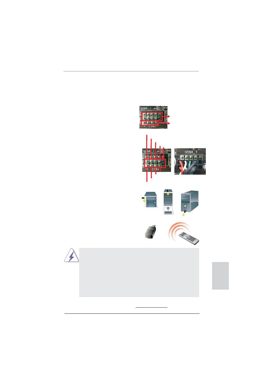
USB 2.0 header (9-pin, black)
CIR header (4-pin, gray)
2.8 ASRock Smart Remote Installation Guide
ASRock Smart Remote is only used for ASRock motherboard with CIR header.
Please refer to below procedures for the quick installation and usage of ASRock
Smart Remote.
Step1.
Find the CIR header located next
to the USB 2.0 header on ASRock
motherboard.
Step2.
Connect the front USB cable to the
USB 2.0 header (as below, pin 1-5)
and the CIR header. Please make
sure the wire assignments and the
pin assignments are matched
correctly.
1 2
4
3
5
USB_PWR
P-
P+
GND
ATX+5VSB
IRRX
IRTX
GND
DUMMY
Step3. Install
Multi-Angle CIR Receiver to
the front USB port. If Multi-Angle
CIR
Receiver cannot successfully
receive the infrared signals from
MCE Remote Controller, please try
to install it to the other front USB
port.
3 CIR sensors in different angles
1.
Only one of the front USB port can support CIR function. When
the CIR function is enabled, the other port will remain USB
function.
2.
Multi-Angle CIR Receiver is used for front USB only. Please do
not use the rear USB bracket to connect it on the rear panel.
Multi-Angle CIR Receiver can receive the multi-direction infrared
signals (top, down and front), which is compatible with most of
the chassis on the market.
3.
The Multi-Angle CIR Receiver does not support Hot-Plug
function. Please install it before you boot the system.
36
ASRock Z68 Extreme7 Gen3 Motherboard
English
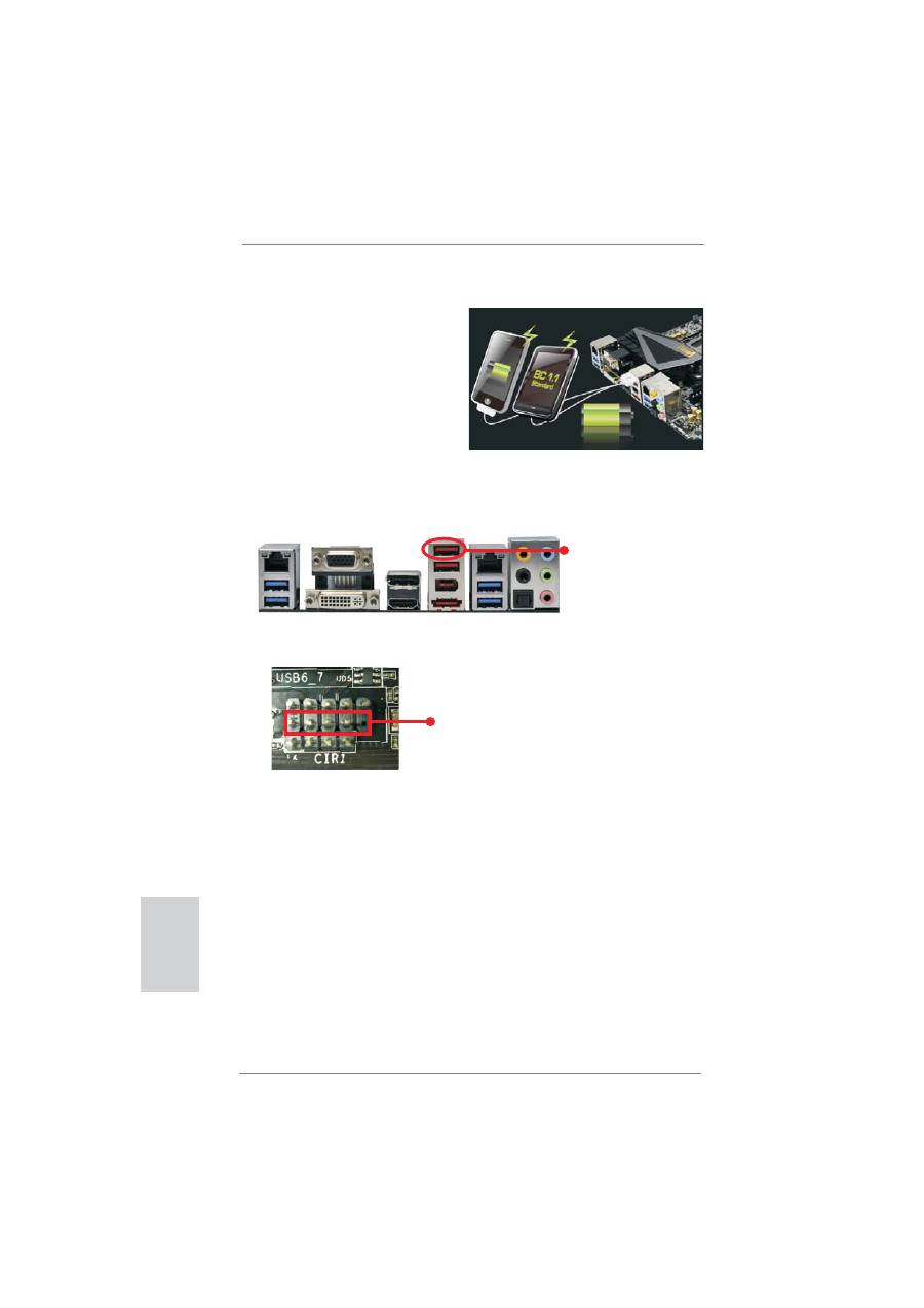
2.9 ASRock XFast Charger Operation Guide
ASRock XFast Charger is the best and
fastest technology to charge your mobile
devices via PC. With the superb XFast
Charger USB port, users are assured to
enjoy the quick charging experience
anytime. In addition to Apple devices, it
is also capable of Charging the BC 1.1
standard smart devices. Please refer to
below instruction for proper operation.
This motherboard provides two USB ports for ASRock XFast Charger:
1. USB 2.0 port (USB0) on the I/O panel
2. USB 2.0 port (USB6) header
With ASRock XFast Charger feature, you can freely enjoy the quick charging
convenience by installing the USB cable on these two ports.
see p.2 No. 27
see p.2 No. 4
37
ASRock Z68 Extreme7 Gen3 Motherboard
English
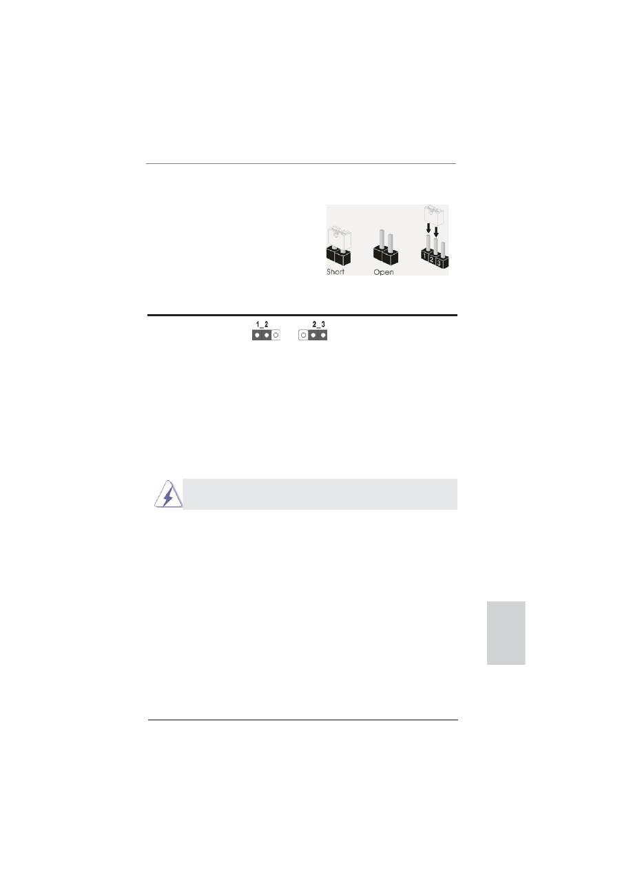
2.10 Jumpers Setup
The illustration shows how jumpers are
setup. When the jumper cap is placed on
pins, the jumper is “Short”. If no jumper cap
is placed on pins, the jumper is “Open”. The
illustration shows a 3-pin jumper whose
pin1 and pin2 are “Short” when jumper cap
is placed on these 2 pins.
Jumper Setting
Description
Clear CMOS Jumper
(CLRCMOS1)
(see p.2, No. 19)
Note: CLRCMOS1 allows you to clear the data in CMOS. To clear and reset the
system parameters to default setup, please turn off the computer and unplug
the power cord from the power supply. After waiting for 15 seconds, use a
jumper cap to short pin2 and pin3 on CLRCMOS1 for 5 seconds. However,
please do not clear the CMOS right after you update the BIOS. If you need
to clear the CMOS when you just
fi
nish updating the BIOS, you must boot
up the system
fi
rst, and then shut it down before you do the clear-CMOS ac-
tion. Please be noted that the password, date, time, user default pro
fi
le, 1394
GUID and MAC address will be cleared only if the CMOS battery is removed.
Clear CMOS
Default
The Clear CMOS Switch has the same function as the Clear CMOS
jumper.
38
ASRock Z68 Extreme7 Gen3 Motherboard
English
2.11 Onboard Headers and Connectors
Onboard headers and connectors are NOT jumpers. Do NOT place
jumper caps over these headers and connectors. Placing jumper caps
over the headers and connectors will cause permanent damage of the
motherboard!
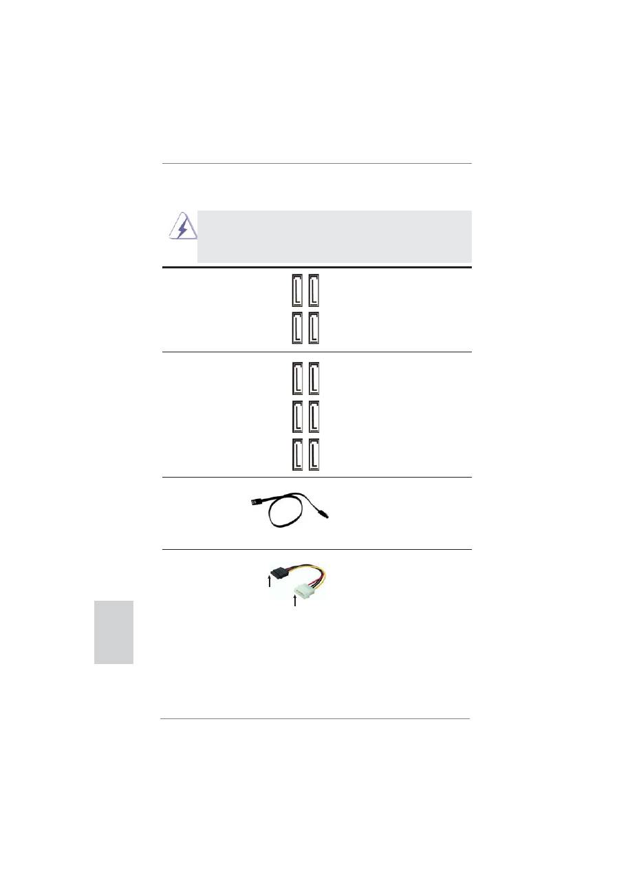
Serial ATAII Connectors
These four Serial ATAII (SATAII)
(SATA2_2_3: see p.2, No. 13)
connectors support SATA data
(SATA2_4_5: see p.2, No. 14)
cables for internal storage
devices. The current SATAII
interface allows up to 3.0 Gb/s
data transfer rate.
SA
TA2_5 SA
TA2_3
SA
TA2_4 SA
TA2_2
Serial ATA (SATA)
Either end of the SATA data
Data Cable
cable can be connected to the
(Optional)
SATA / SATAII / SATA3 hard
disk or the SATAII / SATA3
connector on this motherboard.
connect to the SATA
HDD power connector
connect to the
power supply
Serial ATA (SATA)
Please connect the black end
Power Cable
of SATA power cable to the
(Optional)
power connector on each drive.
Then connect the white end of
SATA power cable to the power
connector of the power supply.
Serial ATA3 Connectors
These six Serial ATA3 (SATA3)
(SATA3_0_1: see p.2, No. 12)
connectors support SATA data
(SATA3_A1_A2: see p.2, No. 10)
cables for internal storage
(SATA3_A3_A4: see p.2, No. 11)
devices. The current SATA3
interface allows up to 6.0 Gb/s
data transfer rate. If you install
the HDD on the eSATA port on
the rear I/O, the internal
SATA3_A4 will not function.
SA
TA3_1 SA
TA3_A4 SA
TA3_A2
SA
TA3_0 SA
TA3_A3 SA
TA3_A1
39
ASRock Z68 Extreme7 Gen3 Motherboard
English
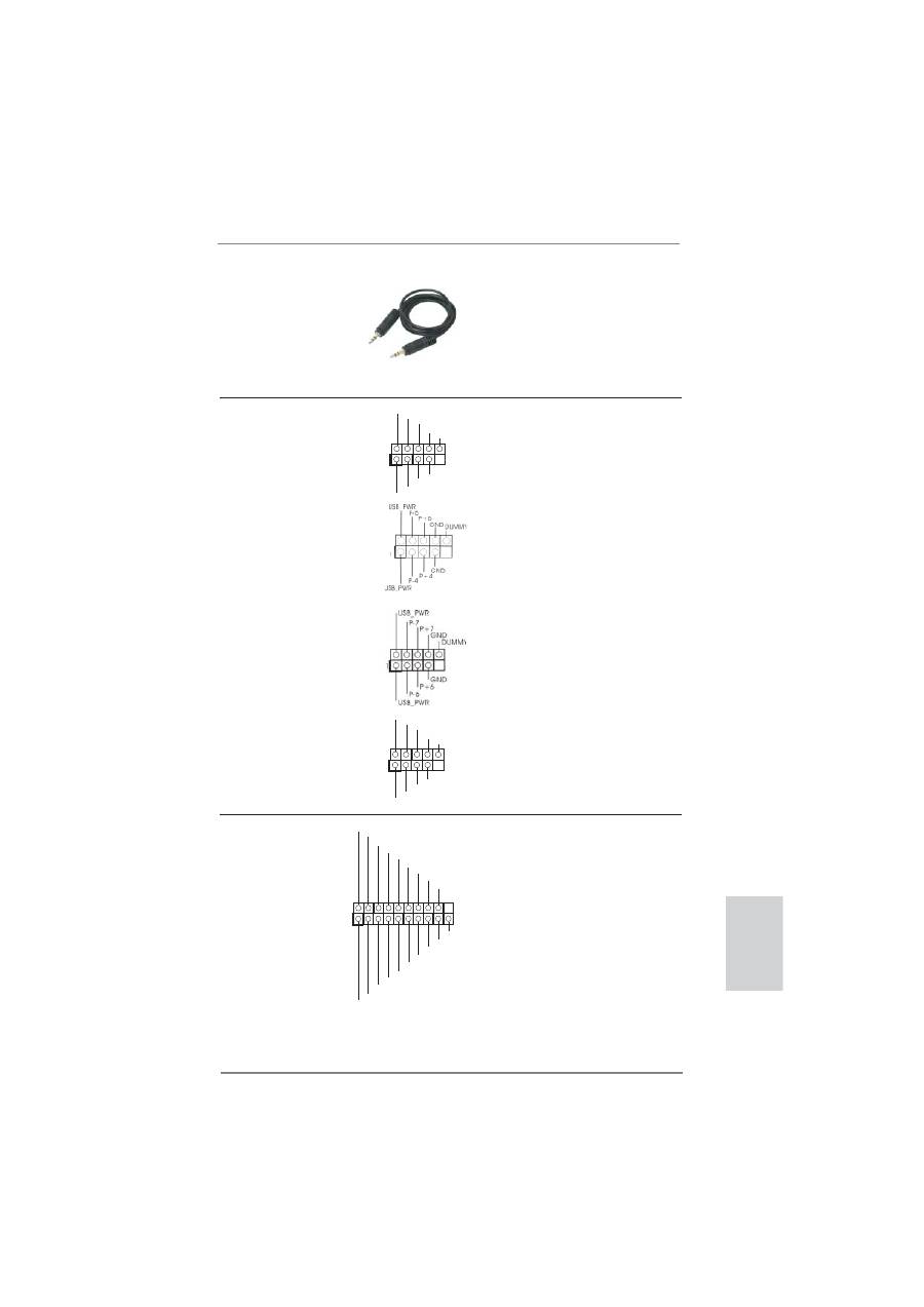
USB 3.0 Header
Besides four default USB 3.0
(19-pin USB3_5_6)
ports on the I/O panel, there is
(see p.2 No. 9)
one USB 3.0 header on this
motherboard. This USB 3.0
header can support two USB
3.0
ports.
1
ID
IntA_P1_D+
IntA_P1_D-
GND
IntA_P1_SSTX+
IntA_P1_SSTX-
GND
IntA_P1_SSRX+
IntA_P1_SSRX-
Vbus
IntA_P2_D+
IntA_P2_D-
GND
IntA_P2_SSTX+
IntA_P2_SSTX-
GND
IntA_P2_SSRX+
IntA_P2_SSRX-
Vbus
1
USB_PWR
P-8
GND
DUMMY
USB_PWR
P+8
GND
P-9
P+9
3.5mm Audio Cable
Either end of the 3.5mm audio
(Optional)
cable can be connected to the
portable audio devices, such
as MP3 player and mobile
phone or the Line-in port of
your
PC.
1
USB_PWR
P-2
GND
DUMMY
USB_PWR
P+2
GND
P-3
P+3
USB 2.0 Headers
Besides two default USB 2.0
(9-pin USB2_3)
ports on the I/O panel, there
(see p.2 No. 25)
are four USB 2.0 headers on
this motherboard. Each
USB 2.0 header can support
two USB 2.0 ports. Please be
(9-pin USB4_5)
noted that USB6 port supports
(see p.2 No. 26)
ASRock XFast Charger. Please
refer to page 40 for detaied
information.
(9-pin USB6_7)
(see p.2 No. 27)
(9-pin USB8_9)
(see p.2 No. 29)
40
ASRock Z68 Extreme7 Gen3 Motherboard
English
Infrared Module Header
This header supports an
(5-pin IR1)
optional wireless transmitting
(see p.2 No. 34)
and receiving infrared module.
1
IRTX
+5VSB
DUMMY
IRRX
GND
Consumer Infrared Module Header
This header can be used to
(4-pin CIR1)
connect the remote
(see p.2 No. 28)
controller
receiver.
1
ATX+5VSB
IRTX
GND
IRRX
1. High De
fi
nition Audio supports Jack Sensing, but the panel wire on
the chassis must support HDA to function correctly. Please follow the
instruction in our manual and chassis manual to install your system.
2. If you use AC’97 audio panel, please install it to the front panel audio
header as below:
A. Connect Mic_IN (MIC) to MIC2_L.
B. Connect Audio_R (RIN) to OUT2_R and Audio_L (LIN) to OUT2_L.
C. Connect Ground (GND) to Ground (GND).
D. MIC_RET and OUT_RET are for HD audio panel only. You don’t
need to connect them for AC’97 audio panel.
E. To activate the front mic.
For Windows
®
XP / XP 64-bit OS:
Select “Mixer”. Select “Recorder”. Then click “FrontMic”.
For Windows
®
7 / 7 64-bit / Vista
TM
/ Vista
TM
64-bit OS:
Go to the "FrontMic" Tab in the Realtek Control panel. Adjust
“Recording Volume”.
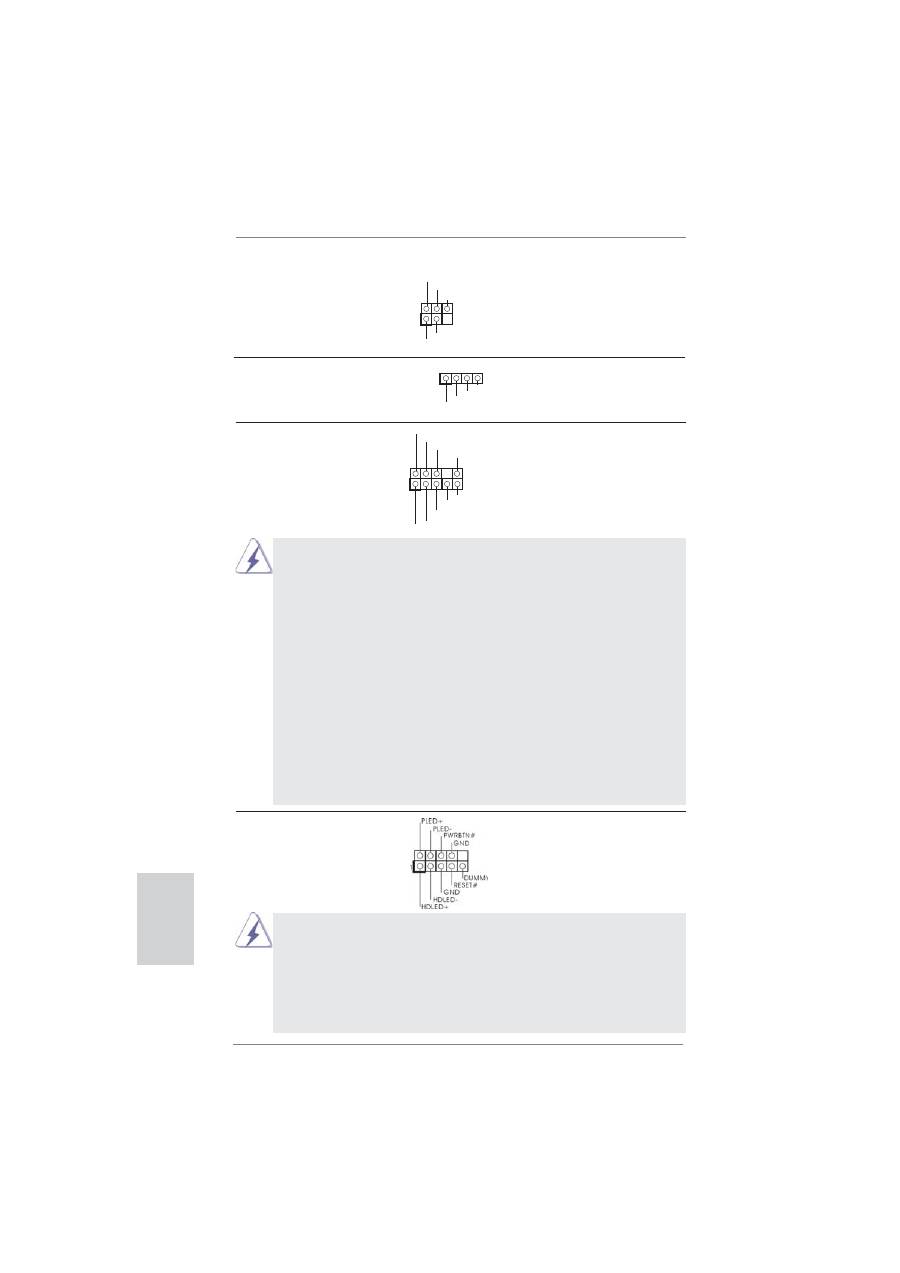
System Panel Header
This header accommodates
(9-pin PANEL1)
several system front panel
(see p.2 No. 21)
functions.
J_SENSE
OUT2_L
1
MIC_RET
PRESENCE#
GND
OUT2_R
MIC2_R
MIC2_L
OUT_RET
Front Panel Audio Header
This is an interface for front
(9-pin HD_AUDIO1)
panel audio cable that allows
(see p.2 No. 36)
convenient connection and
control of audio devices.
Connect the power switch, reset switch and system status indicator on the
chassis to this header according to the pin assignments below. Note the
positive and negative pins before connecting the cables.
PWRBTN (Power Switch):
Connect to the power switch on the chassis front panel. You may con
fi
gure
the way to turn off your system using the power switch.
