ASRock X79 Extreme6__GB – страница 2
Инструкция к Материнской Плате ASRock X79 Extreme6__GB

2.4 Expansion Slots (PCI Express Slots)
There are 2 PCI slots and 4 PCI Express slots on this motherboard.
PCI slots: PCI slots are used to install expansion cards that have the 32-bit PCI
interface.
PCIE slots: PCIE1 / PCIE3 (PCIE 3.0 x16 slots) are used for PCI Express x16 lane
width graphics cards, or used to install PCI Express graphics cards to
TM
TM
support CrossFireX
or SLI
function.
PCIE2 (PCIE 2.0 x1 slot) is used for PCI Express cards with x1 lane
width cards, such as Gigabit LAN card, SATA2 card, etc.
PCIE4 (PCIE 3.0 x16 slot) is used for PCI Express x8 lane width
graphics cards, ASRock Game Blaster, or used to install PCI Express
TM
TM
graphics cards to support 3-Way CrossFireX
or 3-Way SLI
function.
1. In single VGA card mode, it is recommended to install a PCI Express
x16 graphics card on PCIE1 slot.
TM
TM
2. In CrossFireX
mode or SLI
mode, please install PCI Express x16
graphics cards on PCIE1 and PCIE3 slots. Therefore, both these two
slots will work at x16 bandwidth.
TM
TM
3. In 3-Way CrossFireX
or 3-Way SLI
mode, please install PCI
Express x16 graphics cards on PCIE1, PCIE3 and PCIE4 slots.
Therefore, PCIE1 and PCIE3 will work at x16 bandwidth, while PCIE4
works at x8 bandwidth.
4. If ASRock Game Blaster is installed, this motherboard cannot support
TM
TM
CrossFireX
or SLI
with 3-space graphics cards. If ASRock Game
Blaster is installed, this motherboard cannot support 3-Way
TM
TM
CrossFireX
or 3-Way SLI
.
5. Please connect a chassis fan to motherboard chassis fan connector
(CHA_FAN1, CHA_FAN2 or CHA_FAN3) when using multiple
graphics cards for better thermal environment.
®
6. Currently Intel
Socket 2011 Sandy Bridge-E Processor doesn’t
support PCIE 3.0, but this motherboard is already PCIE 3.0 hardware
ready. It depends on Intel’s CPU to enable PCIE 3.0. Please check
Intel’s website for information on future CPU updates and releases.
Installing an expansion card
Step 1. Before installing the expansion card, please make sure that the power
supply is switched off or the power cord is unplugged. Please read the
documentation of the expansion card and make necessary hardware
settings for the card before you start the installation.
English
Step 2. Remove the system unit cover (if your motherboard is already installed
in a chassis).
Step 3. Remove the bracket facing the slot that you intend to use. Keep the
screws for later use.
21
ASRock X79 Extreme6/GB / X79 Extreme6 Motherboard
Step 4. Align the card connector with the slot and press rmly until the card is
completely seated on the slot.
Step 5. Fasten the card to the chassis with screws.
Step 6. Replace the system cover.
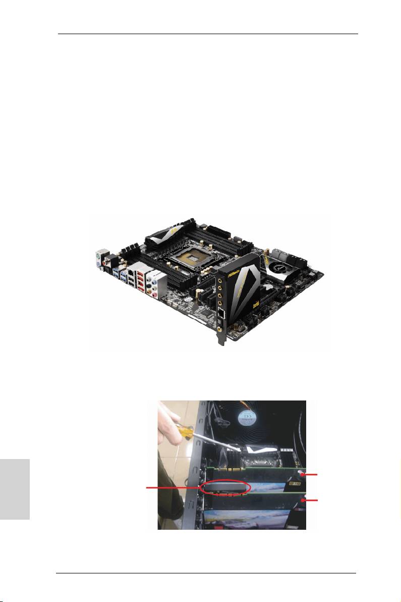
2.5 ASRock Game Blaster Installation Guide (X79 Extreme6/GB)
2.5.1 ASRock Game Blaster and Driver Installation
Step 1. Please refer to the “Expansion Slots” section then insert ASRock Game
Blaster into PCIE4 slot.
Step 2. In order to avoid mechanical conict, please fasten your VGA cards and
ASRock Game Blaster to the chassis with screws.
English
VGA card
ASRock Game
Blaster
VGA card
22
ASRock X79 Extreme6/GB / X79 Extreme6 Motherboard
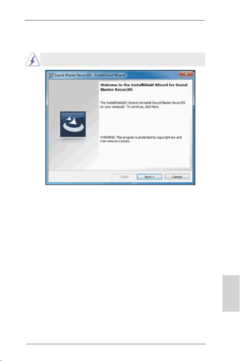
Step 3. Follow the step by step driver setup directions. Please make sure to use
®
TM
®
Windows
Vista
32-bit / 64-bit or Windows
7 32-bit / 64-bit.
®
ASRock Game Blaster is not supported under Windows
XP / XP 64-bit.
Step 4. Restart your computer for ASRock Game Blaster to take effect.
English
23
ASRock X79 Extreme6/GB / X79 Extreme6 Motherboard
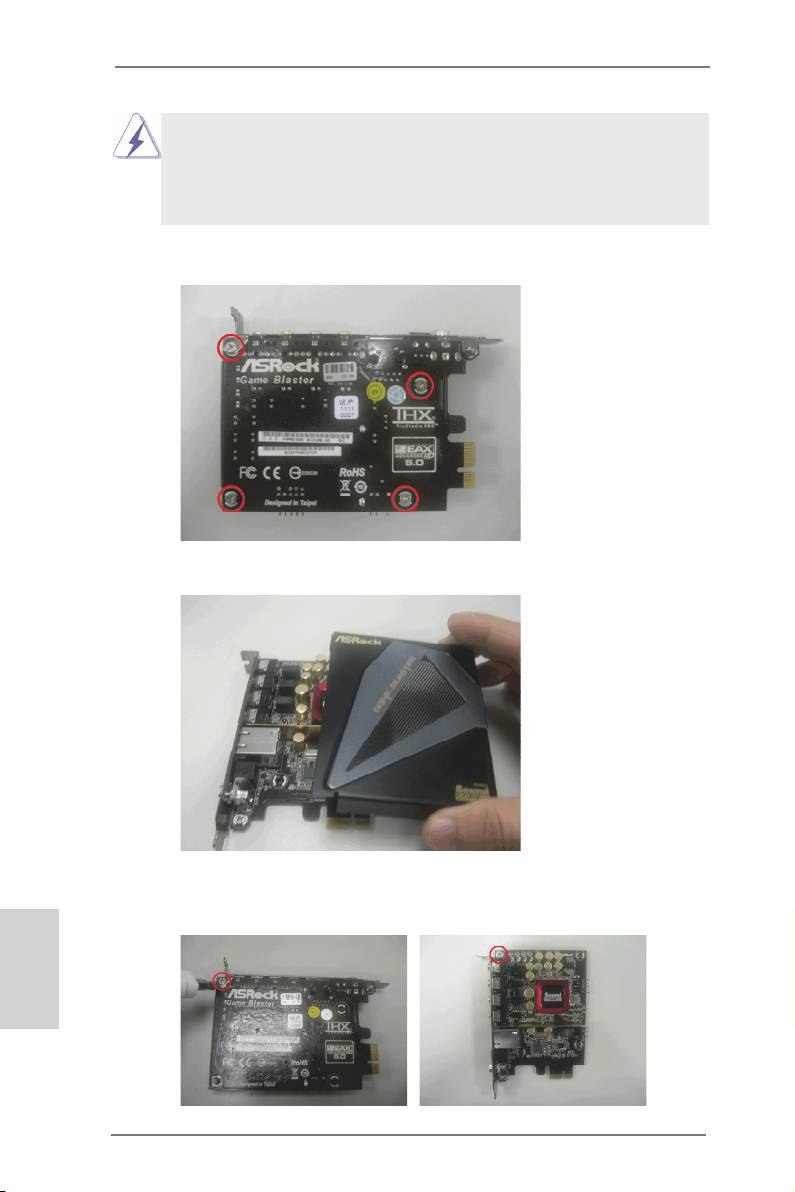
Some VGA cards violate the PCI-E spec and may result in mechanical
conict with ASRock Game Blaster. In this case, we suggest you to follow
the steps below to uninstall the chassis of the ASRock Game Blaster to x
the conict.
Step 1. Unscrew the four screws which hold the chassis and ASRock Game
Blaster together.
Step 2. Remove the chassis of the ASRock Game Blaster.
Step 3. Refasten the screw on the upper left corner and secure it with the screw
nut which is bundled with ASRock Game Blaster.
English
24
ASRock X79 Extreme6/GB / X79 Extreme6 Motherboard
2.5.2 ASRock Game Blaster Configuration
This section explains how to congure your ASRock Game Blaster.
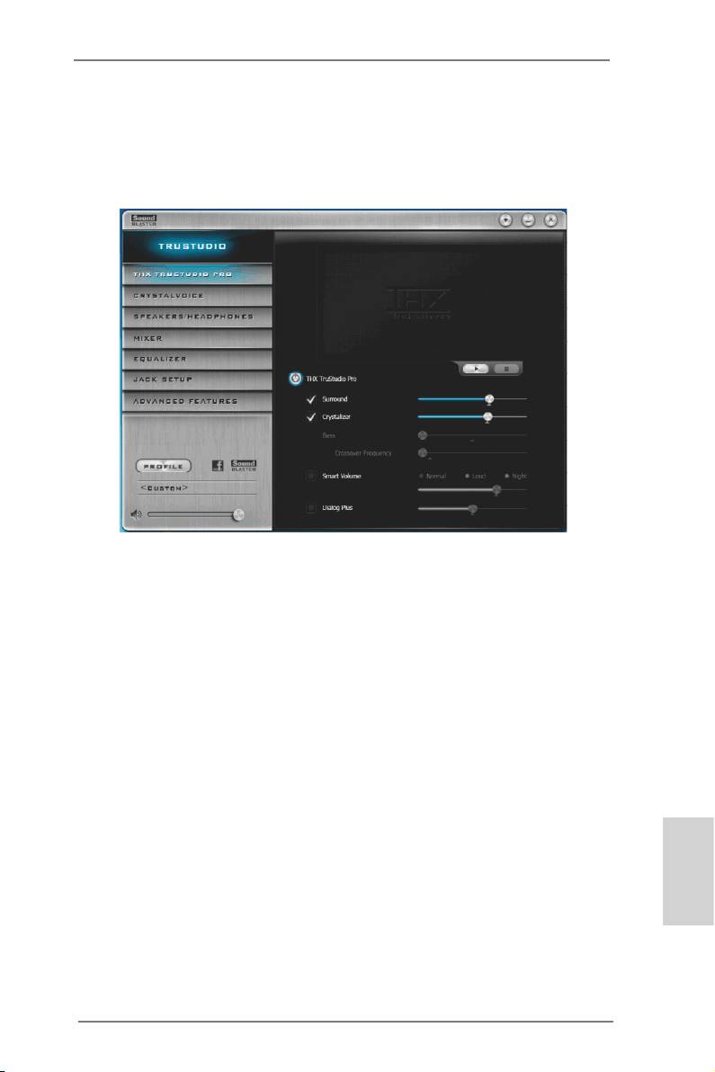
2.5.2.1 THX TRUSTUDIO PRO
THX TruStudio Pro
Click the power button on the left to activate or deactivate.
Surround
Control the level of audio immersion in music, movies and games.
Crystalizer
Enhance music and movies to make them sound livelier.
Bass
Control the desired level of bass.
Crossover Frequency
Redirect all frequencies below this value to the optimal speaker for
better bass response.
Smart Volume
Adjust the loudness of your audio playback automatically to minimize
sudden volume changes.
Dialog Plus
Enhance the voices in movies for clearer dialog.
English
25
ASRock X79 Extreme6/GB / X79 Extreme6 Motherboard
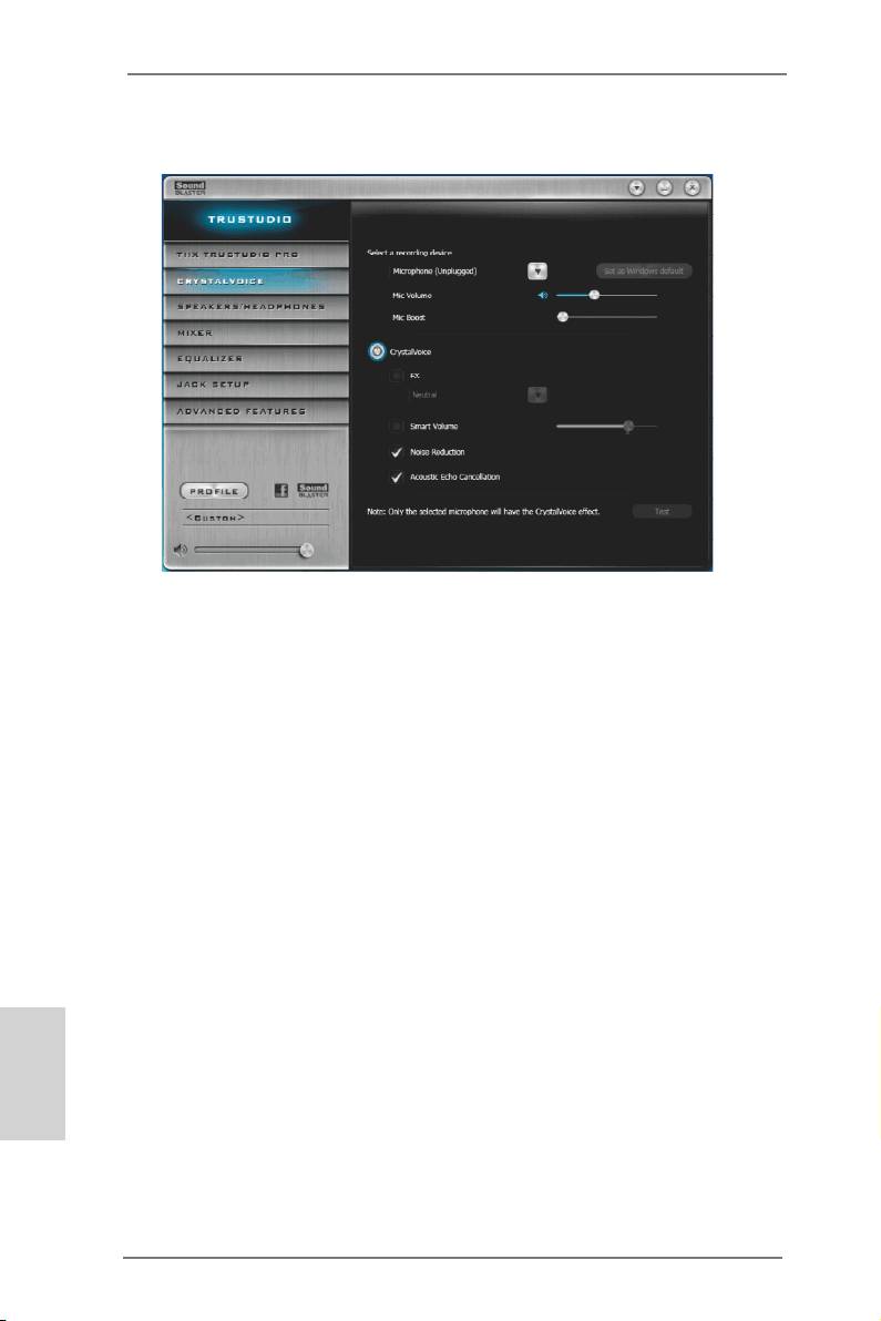
2.5.2.2 CRYSTALVOICE
Select a recording device
Mic Volume
Control the level of mic volume.
Mic Boost
Control the level of mic boost.
CrystalVoice
Click the power button on the left to activate or deactivate.
FX
Morph your voice into different characters and accents.
Smart Volume
Be heard clearly without having to shout or whisper.
Noise Reduction
Eliminate unwanted background noise in your conversation.
Acoustic Echo Cancellation
Eliminate echoes that interfere with your conversation.
English
26
ASRock X79 Extreme6/GB / X79 Extreme6 Motherboard
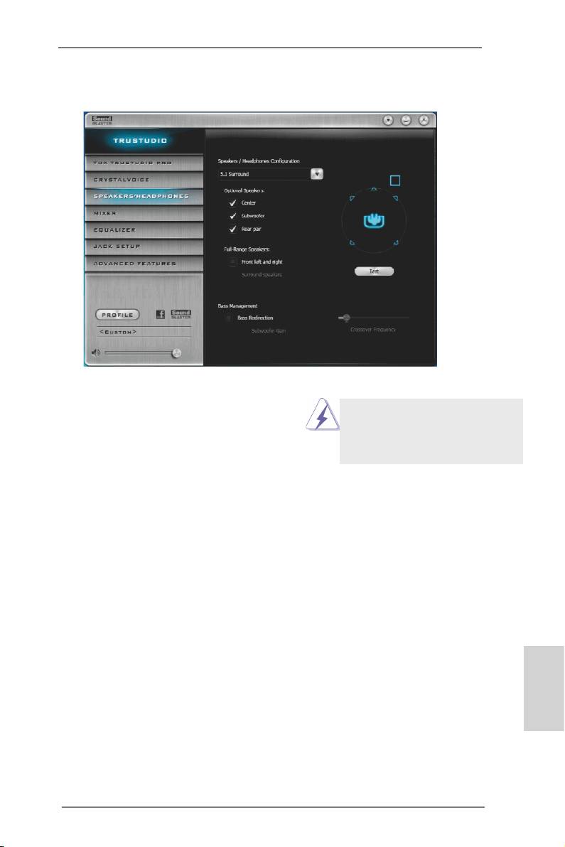
2.5.2.3 SPEAKERS/HEADPHONES
Speakers / Headphones Conguration
Select the device connected.
If there are both speakers and
Optional Speakers:
front headphones connected,
please select the device you
Center
desire to use as audio output.
Enable or disable center speaker.
Subwoofer
Enable or disable subwoofer.
Rear pair
Enable or disable rear pair speakers.
Full-Range Speakers:
Select full-range speakers.
Front left and right
Surround speakers
Bass Management
Bass Redirection
Enable or disable bass redirection.
Subwoofer Gain
English
Enable or disable subwoofer gain.
Crossover Frequency
Redirect all frequencies below this value to the optimal speaker for better
bass response.
27
ASRock X79 Extreme6/GB / X79 Extreme6 Motherboard

2.5.2.4 MIXER
Playback
Speakers
Control the level of speakers playback.
SPDIF-Out
Control the level of SPDIF-Out playback.
Balance
Control the level of various speaker’s balance.
REC
Input Device
Select input device.
What U Hear
Control the level of playback redirect.
English
28
ASRock X79 Extreme6/GB / X79 Extreme6 Motherboard
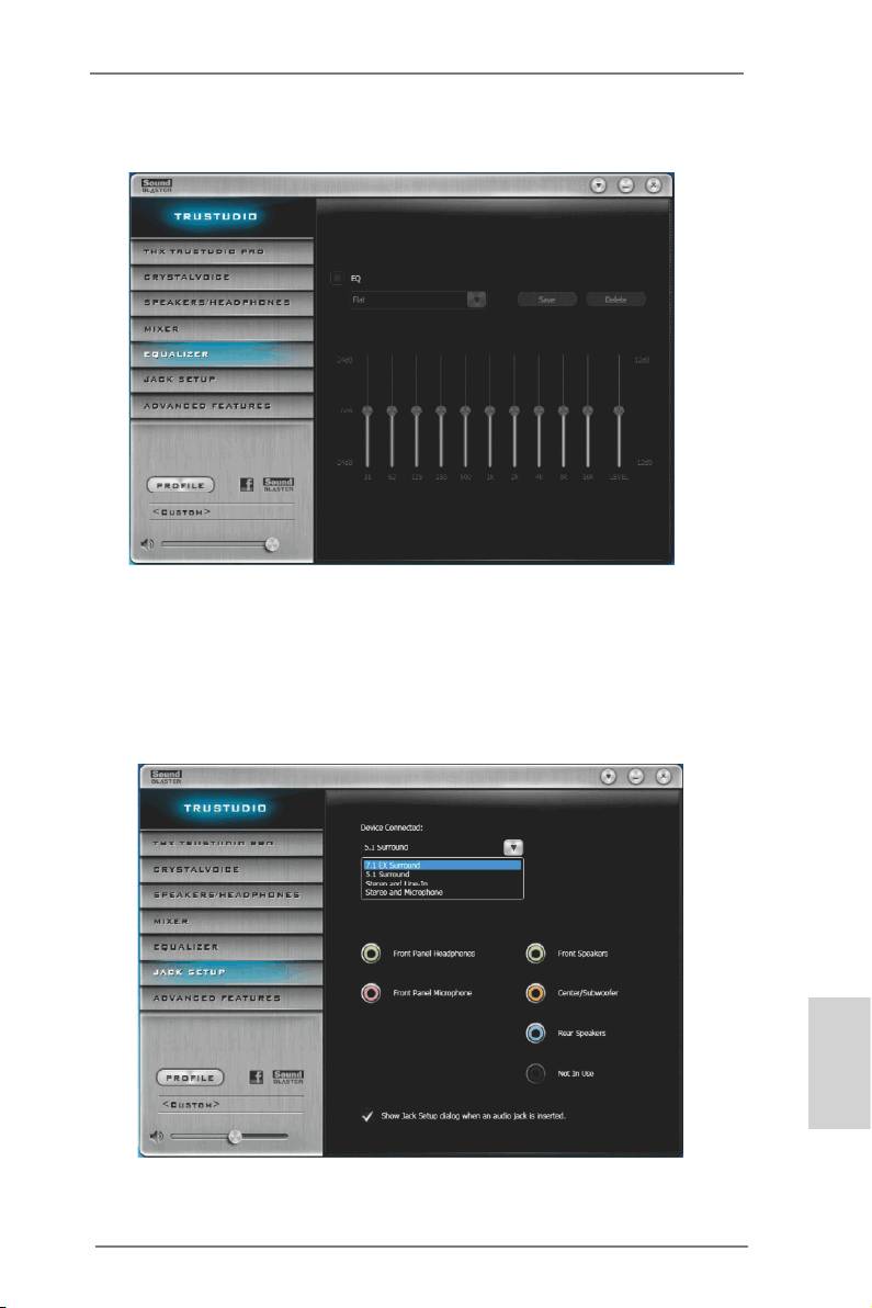
2.5.2.5 EQUALIZER
EQ
Choose from Flat, Acoustic, Classical, Country, Dance, Jazz, New Age, Pop,
Rock and Vocal.
2.5.2.6 JACK SETUP
English
29
ASRock X79 Extreme6/GB / X79 Extreme6 Motherboard
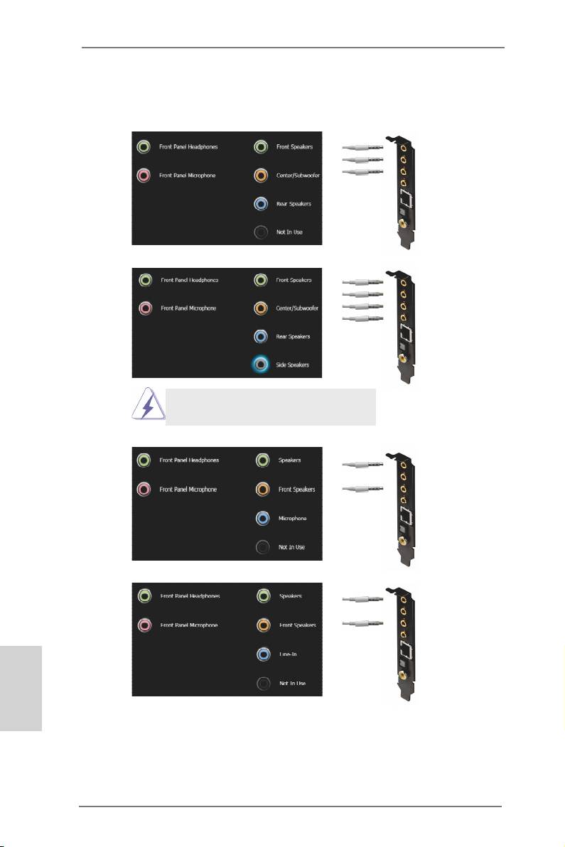
Device Connected:
Select the device connected.
5.1 Surround
Front Speakers
Center/Subwoofer
Rear Speakers
7.1 EX Surround
Front Speakers
Center/Subwoofer
Rear Speakers
Side Speakers
Front panel headphones is shared with
side speakers.
Stereo and Microphone
Speakers
Microphone
Stereo and Line-In
Speakers
Line-In
English
Show Jack Setup dialog when an audio jack is inserted
Enable or disable Jack Setup dialog.
30
ASRock X79 Extreme6/GB / X79 Extreme6 Motherboard
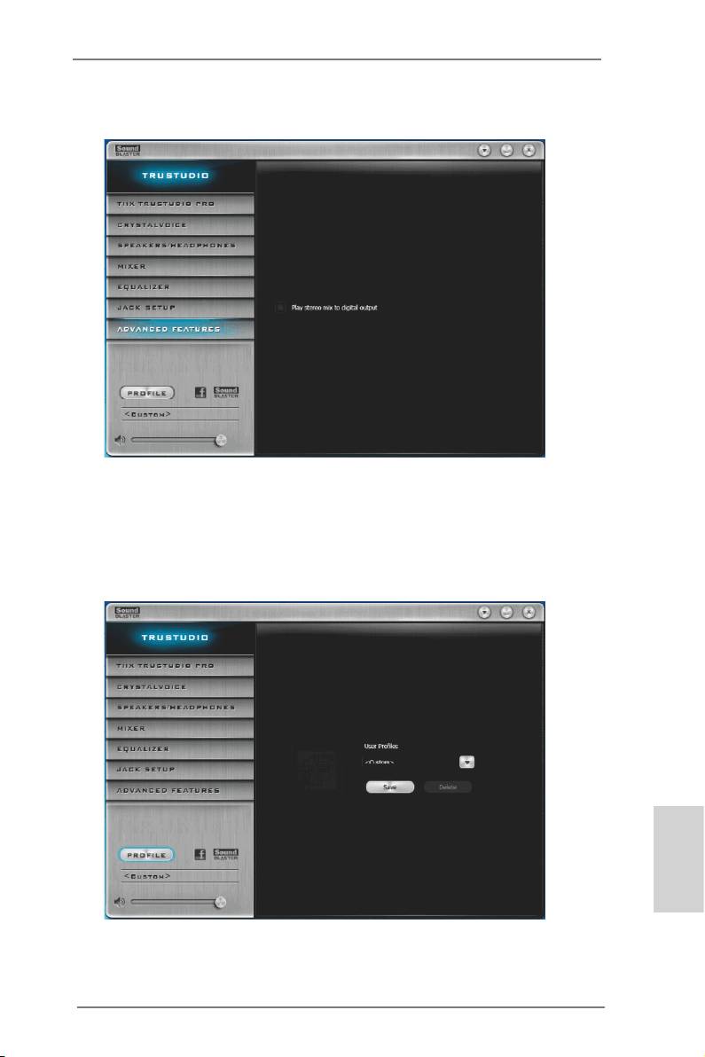
2.5.2.7 ADVANCED FEATURES
Play stereo mix to digital output
Enable or disable play stereo mix to digital output.
2.5.2.8 PROFILE
English
User Proles
You can save, load or delete your user proles. The default is <Custom>.
31
ASRock X79 Extreme6/GB / X79 Extreme6 Motherboard
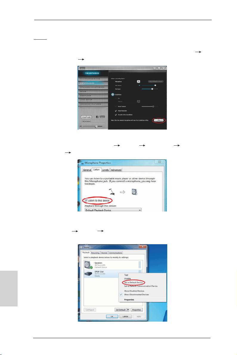
Note
1. If you want to hear your own voice through the microphone (Playback mode).
You can enable it by using ASRock Game Blaster's conguration Utility
CRYSTALVOICE Test.
OR you can change your settings to "playback mode" by checking the "Listen to
this device" box in Control panel Sound Recording Microphone
Properties Listen.
2. If you want to change your playback device to a SPDIF-Out device, go into
Control panel Sound Playback, then right click on SPDIF-Out and
check the "Set as Default Device" option.
English
32
ASRock X79 Extreme6/GB / X79 Extreme6 Motherboard
TM
TM
TM
2.6 SLI
, 3-Way SLI
and Quad SLI
Operation Guide
®
TM
TM
TM
This motherboard supports NVIDIA
SLI
, 3-Way SLI
and Quad SLI
(Scalable
Link Interface) technology that allows you to install up to three identical PCI Express
®
TM
®
x16 graphics cards. Currently, NVIDIA
SLI
technology supports Windows
XP /
TM
TM
®
TM
XP 64-bit / Vista
/ Vista
64-bit / 7 / 7 64-bit OS. NVIDIA
3-Way SLI
and Quad
TM
®
TM
TM
SLI
technology support Windows
Vista
/ Vista
64-bit / 7 / 7 64-bit OS only.
Please follow the installation procedures in this section.
Requirements
TM
TM
1. For SLI
technology, you should have two identical SLI
-ready graphics
®
TM
cards that are NVIDIA
certied. For 3-Way SLI
technology, you should
TM
®
have three identical 3-Way SLI
-ready graphics cards that are NVIDIA
TM
certied. For Quad SLI
technology, you should have two identical Quad
TM
®
SLI
-ready graphics cards that are NVIDIA
certied.
®
TM
2. Make sure that your graphics card driver supports NVIDIA
SLI
technology
(driver version 280.41 and later). Download the driver from NVIDIA website
(www.nvidia.com).
3. Make sure that your power supply unit (PSU) can provide at least the
minimum power required by your system. It is recommended to use
®
®
NVIDIA
certied PSU. Please refer to NVIDIA
website for details.
2.6.1 Graphics Card Setup
TM
2.6.1.1 Installing Two SLI
-Ready Graphics Cards
TM
®
Step 1. Install the identical SLI
-ready graphics cards that are NVIDIA
certied
because different types of graphics cards will not work together properly.
(Even the GPU chips version shall be the same.) Insert one graphics card
into PCIE1 slot and the other graphics card to PCIE3 slot. Make sure that
the cards are properly seated on the slots.
English
Step2. If required, connect the auxiliary power source to the PCI Express graph-
ics cards.
33
ASRock X79 Extreme6/GB / X79 Extreme6 Motherboard
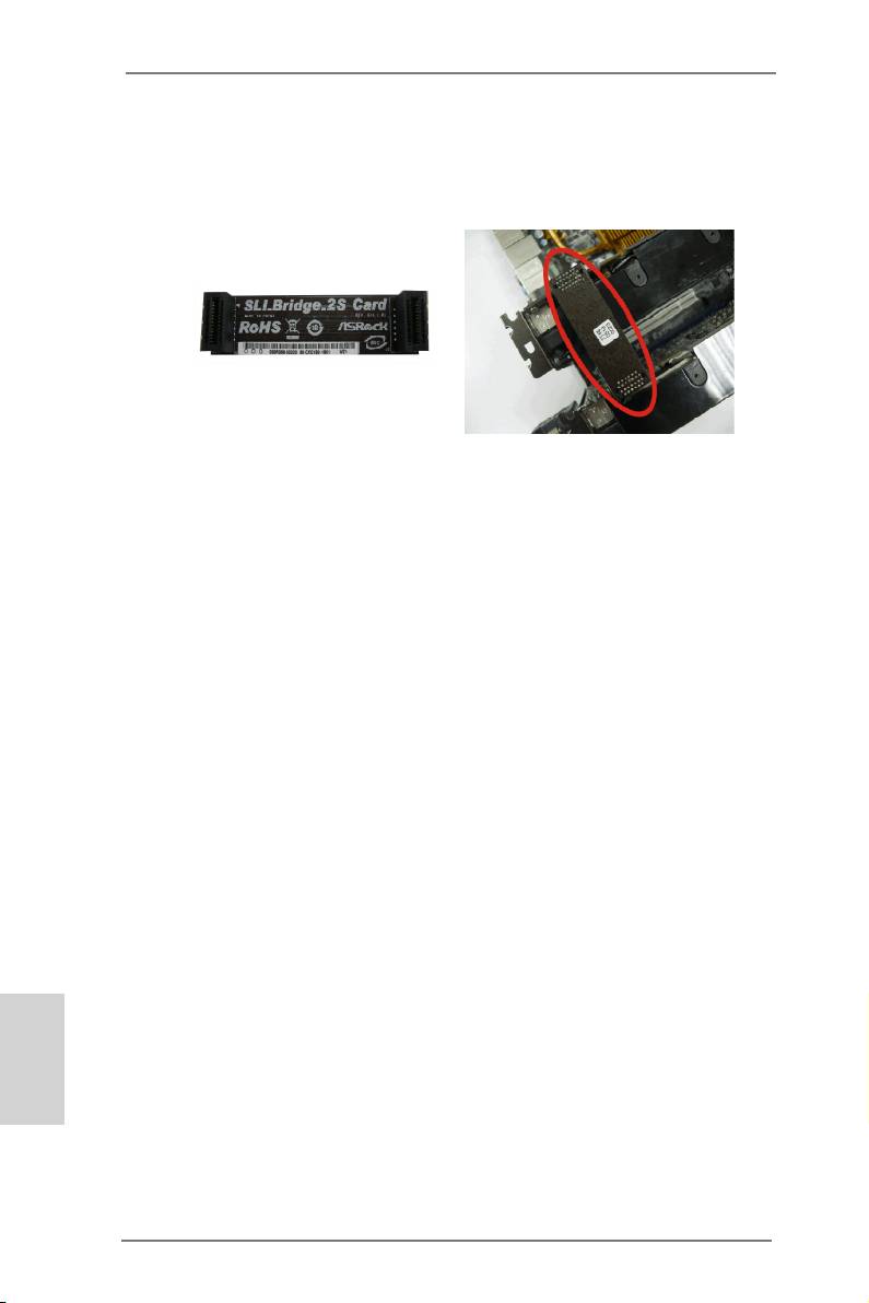
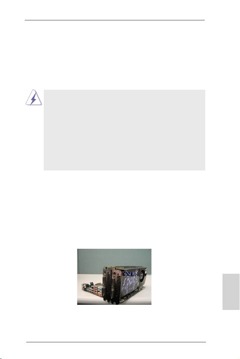
Step3. Align and insert the ASRock SLI_Bridge_2S Card to the goldngers on
each graphics card. Make sure the ASRock SLI_Bridge_2S Card is rmly
in place.
ASRock SLI_Bridge_2S Card
Step4. Connect a VGA cable or a DVI cable to the monitor connector or the DVI
connector of the graphics card that is inserted to PCIE1 slot.
English
34
ASRock X79 Extreme6/GB / X79 Extreme6 Motherboard
TM
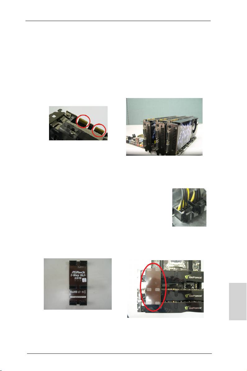
2.6.1.2 Installing Three SLI
-Ready Graphics Cards
TM
®
Step 1. Install the identical 3-Way SLI
-ready graphics cards that are NVIDIA
certied because different types of graphics cards will not work together
properly. (Even the GPU chips version shall be the same.) Each graph-
ics card should have two goldngers for ASRock 3-Way SLI-2S1S Bridge
Card connector. Insert one graphics card into PCIE1 slot, another graphics
card to PCIE3 slot, and the other graphics card to PCIE4 slot. Make sure
that the cards are properly seated on the slots.
Two Goldngers
Step2. Connect the auxiliary power source to the PCI Express graphics card.
Please make sure that both power connectors on the PCI Express graph-
ics card are connected. Repeat this step on the three graphics cards.
Step3. Align and insert ASRock 3-Way SLI-2S1S Bridge Card to the goldngers
on each graphics card. Make sure ASRock 3-Way SLI-2S1S Bridge Card
is rmly in place.
English
ASRock 3-Way SLI-2S1S Bridge Card
Step4. Connect a VGA cable or a DVI cable to the monitor connector or the DVI
connector of the graphics card that is inserted to PCIE1 slot.
35
ASRock X79 Extreme6/GB / X79 Extreme6 Motherboard
2.6.2 Driver Installation and Setup
Install the graphics card drivers to your system. After that, you can enable the Multi-
®
Graphics Processing Unit (GPU) feature in the NVIDIA
nView system tray utility.
Please follow the below procedures to enable the multi-GPU feature.
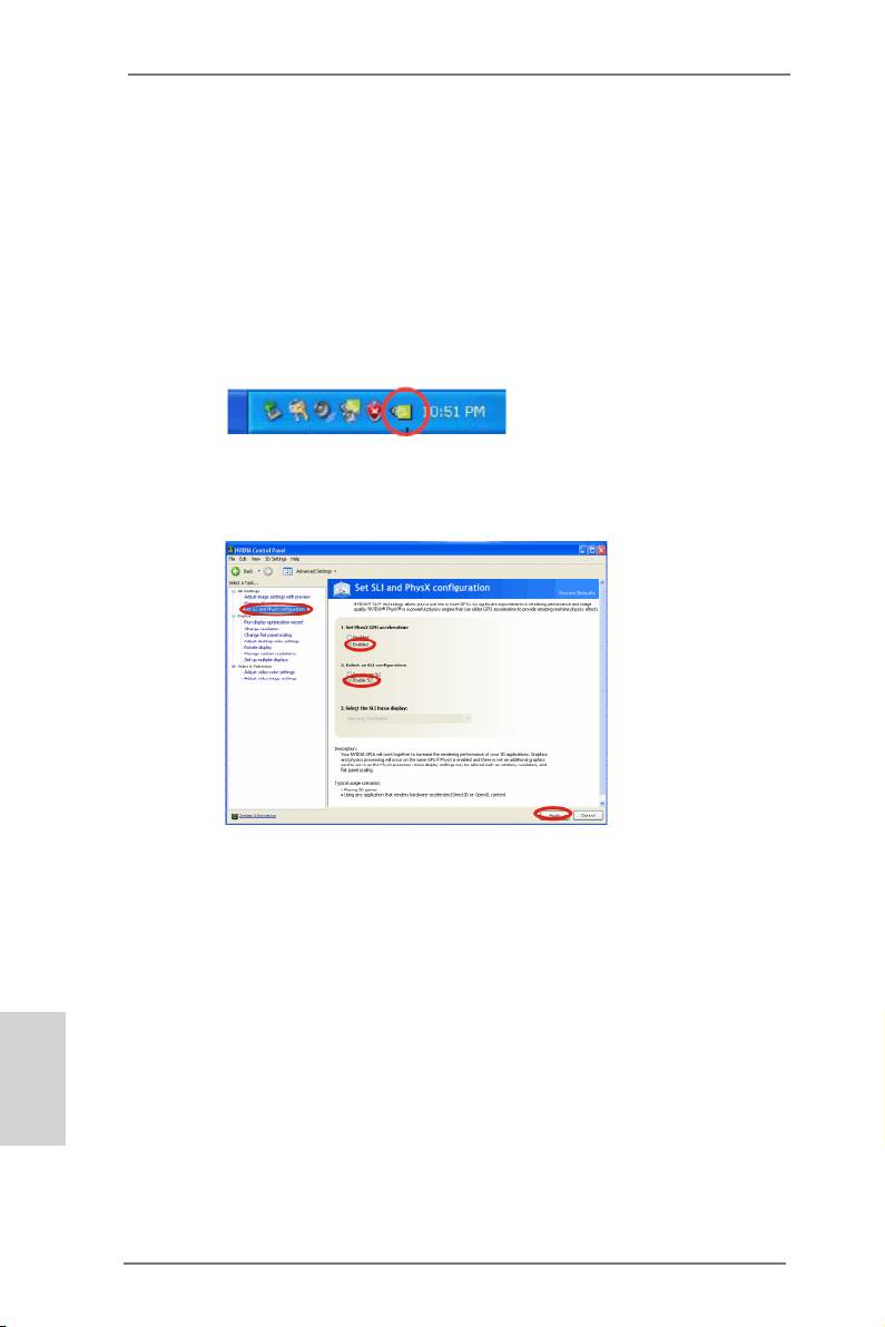
®
For Windows
XP / XP 64-bit OS:
TM
(For SLI
mode only)
®
A. Double-click NVIDIA Settings icon on your Windows
taskbar.
B. From the pop-up menu, select Set SLI and PhysX conguration. In
Set PhysX GPU acceleration item, please select Enabled. In Select
an SLI conguration item, please select Enable SLI. And click Apply.
C. Reboot your system.
TM
D. You can freely enjoy the benet of SLI
feature.
English
36
ASRock X79 Extreme6/GB / X79 Extreme6 Motherboard
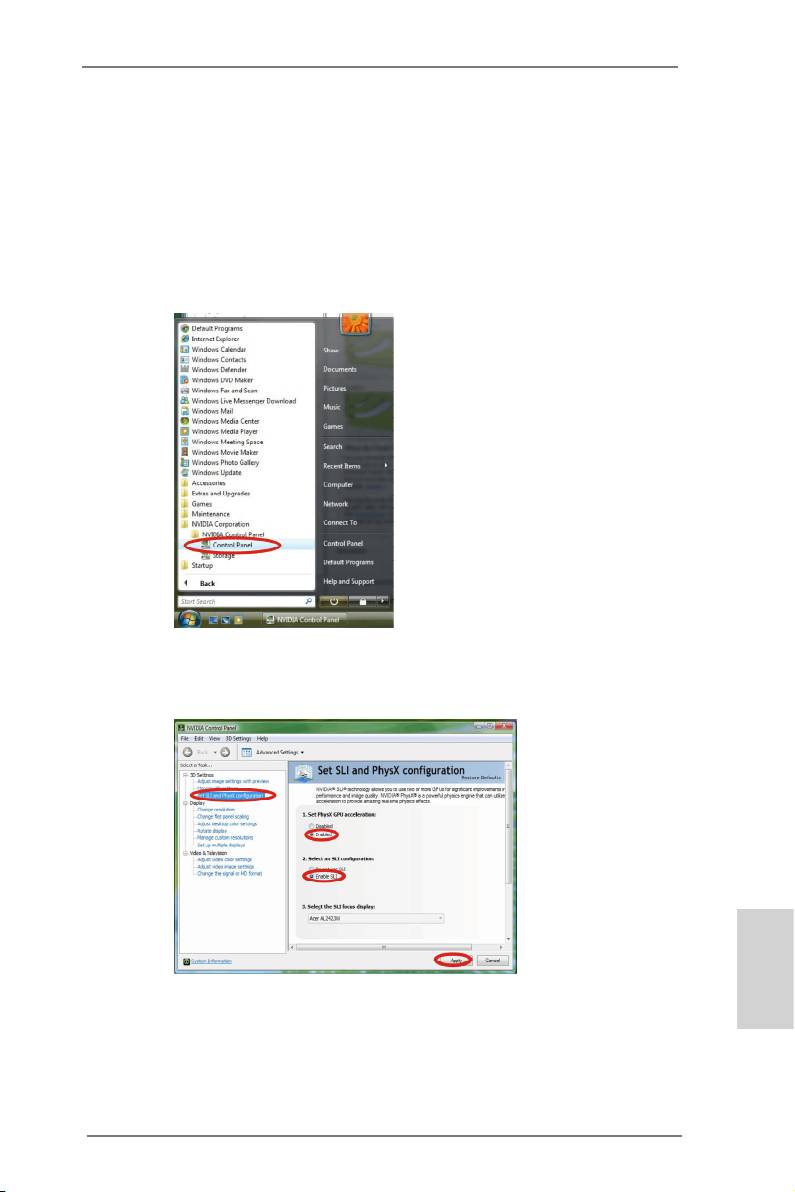
®
TM
TM
For Windows
Vista
/ Vista
64-bit / 7 / 7 64-bit OS:
TM
TM
(For SLI
and Quad SLI
mode)
A. Click the Start icon on your Windows taskbar.
B. From the pop-up menu, select All Programs, and then click NVIDIA
Corporation.
C. Select NVIDIA Control Panel tab.
D. Select Control Panel tab.
E. From the pop-up menu, select Set SLI and PhysX conguration. In
Set PhysX GPU acceleration item, please select Enabled. In Select
an SLI conguration item, please select Enable SLI. And click Apply.
F. Reboot your system.
English
TM
TM
G. You can freely enjoy the benet of SLI
or Quad SLI
feature.
37
ASRock X79 Extreme6/GB / X79 Extreme6 Motherboard
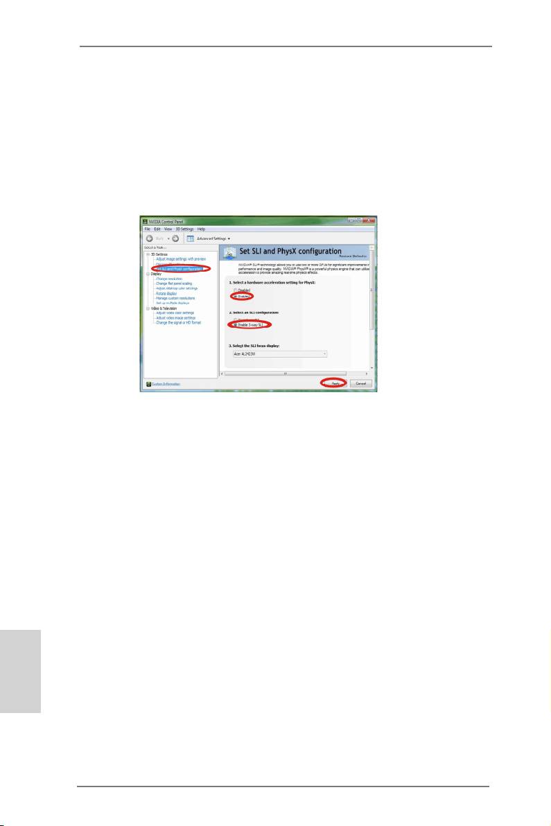
®
TM
TM
For Windows
Vista
/ Vista
64-bit / 7 / 7 64-bit OS:
TM
(For 3-Way SLI
mode)
A. Follow steps A to D on page 37.
B. From the pop-up menu, select Set SLI and PhysX conguration. In
Select a hardware acceleration setting for PhysX item, please
select Enabled. In Select an SLI conguration item, please select
Enable 3-way SLI. And click Apply.
C. Reboot your system.
TM
D. You can freely enjoy the benet of 3-Way SLI
feature.
TM
®
* SLI
appearing here is a registered trademark of NVIDIA
Technologies Inc., and is used
only for identication or explanation and to the owners’ benet, without intent to infringe.
English
38
ASRock X79 Extreme6/GB / X79 Extreme6 Motherboard
TM
TM
TM
2.7 CrossFireX
, 3-Way CrossFireX
and Quad CrossFireX
Operation Guide
TM
TM
This motherboard supports CrossFireX
, 3-way CrossFireX
and Quad
TM
TM
CrossFireX
feature. CrossFireX
technology offers the most advantageous
means available of combining multiple high performance Graphics Processing
Units (GPU) in a single PC. Combining a range of different operating modes with
TM
intelligent software design and an innovative interconnect mechanism, CrossFireX
enables the highest possible level of performance and image quality in any 3D
TM
®
application. Currently CrossFireX
feature is supported with Windows
XP with
TM
TM
TM
Service Pack 2 / Vista
/ 7 OS. 3-way CrossFireX
and Quad CrossFireX
feature
®
TM
are supported with Windows
Vista
/ 7 OS only. Please check AMD website for
TM
TM
ATI
CrossFireX
driver updates.
1. If a customer incorrectly congures their system they will not see the
TM
TM
performance benets of CrossFireX
. All three CrossFireX
components, a
TM
TM
CrossFireX
Ready graphics card, a CrossFireX
Ready motherboard and a
TM
CrossFireX
Edition co-processor graphics card, must be installed correctly to
TM
benet from the CrossFireX
multi-GPU platform.
TM
2. If you pair a 12-pipe CrossFireX
Edition card with a 16-pipe card, both cards
TM
will operate as 12-pipe cards while in CrossFireX
mode.
2.7.1 Graphics Card Setup
TM
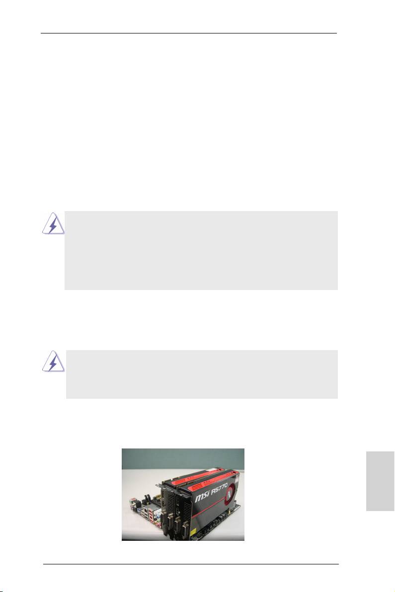
2.7.1.1 Installing Two CrossFireX
-Ready Graphics Cards
TM
TM
Different CrossFireX
cards may require different methods to enable CrossFireX
feature. In below procedures, we use Radeon HD 5770 as the example graphics
TM
card. For other CrossFireX
cards that AMD has released or will release in the
future, please refer to AMD graphics card manuals for detailed installation guide.
Step 1. Insert one Radeon graphics card into PCIE1 slot and the other Radeon
graphics card to PCIE3 slot. Make sure that the cards are properly seated
on the slots.
English
39
ASRock X79 Extreme6/GB / X79 Extreme6 Motherboard

Step 2. Connect two Radeon graphics cards by installing CrossFire Bridge on
CrossFire Bridge Interconnects on the top of Radeon graphics cards.
(CrossFire Bridge is provided with the graphics card you purchase, not
bundled with this motherboard. Please refer to your graphics card vendor
for details.)
CrossFire Bridge
or
Step 3. Connect the DVI monitor cable to the DVI connector on the Radeon
graphics card on PCIE1 slot. (You may use the DVI to D-Sub adapter to
convert the DVI connector to D-Sub interface, and then connect the D-Sub
monitor cable to the DVI to D-Sub adapter.)
English
40
ASRock X79 Extreme6/GB / X79 Extreme6 Motherboard
