ASRock Q77M vPro – страница 2
Инструкция к Материнской Плате ASRock Q77M vPro
2.7.2 Driver Installation and Setup
Step 1. Power on your computer and boot into OS.
Step 2. Remove the AMD drivers if you have any VGA drivers installed in your
system.
The Catalyst Uninstaller is an optional download. We recommend using this utility to
uninstall any previously installed Catalyst drivers prior to installation.
Please check AMD’s website for AMD driver updates.
Step 3. Install the required drivers to your system.
®
For Windows
XP OS:
®
A. AMD recommends Windows
XP Service Pack 2 or higher to be
®
installed (If you have Windows
XP Service Pack 2 or higher installed in
your system, there is no need to download it again):
http://www.microsoft.com/windowsxp/sp2/default.mspx
B. You must have Microsoft .NET Framework installed prior to
downloading and installing the CATALYST Control Center. Please check
Microsoft’s website for details.
®
TM
For Windows
7 / Vista
OS:
Install the CATALYST Control Center. Please check AMD’s website for de-
tails.
Step 4. Restart your computer.
Step 5. Install the VGA card drivers to your system, and restart your computer.
®
You will nd “AMD Catalyst Control Center” on your Windows
taskbar.
AMD Catalyst Control Center
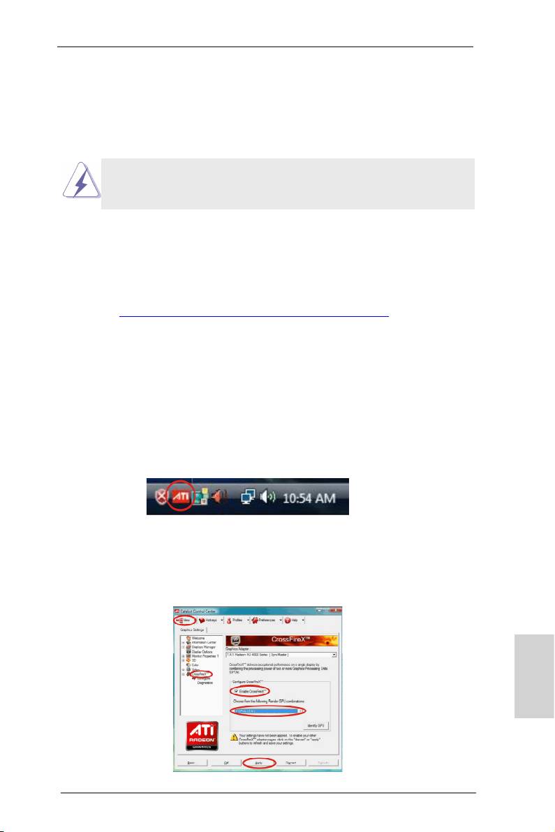
Step 6. Double-click “AMD Catalyst Control Center”. Click “View”, select “CrossFi-
TM
TM
reX
”, and then check the item “Enable CrossFireX
”. Select “2 GPUs”
and click “Apply” (if you install two Radeon graphics cards).
English
21
ASRock Q77M vPro Motherboard
TM
TM
Although you have selected the option “Enable CrossFire
”, the CrossFireX
function may not work actually. Your computer will automatically reboot. After
TM
restarting your computer, please conrm whether the option “Enable CrossFire
” in
“AMD Catalyst Control Center” is selected or not; if not, please select it again, and
TM
then you are able to enjoy the benets of CrossFireX
.
TM
TM
Step 7. You can freely enjoy the benets of CrossFireX
or Quad CrossFireX
.
TM
* CrossFireX
appearing here is a registered trademark of AMD Technologies Inc., and is
used only for identication or explanation and to the owners’ benet, without intent to infringe.
TM
* For further information of AMD CrossFireX
technology, please check AMD’s website for
updates and details.
English
22
ASRock Q77M vPro Motherboard
2.8 Dual Monitor and Surround Display Features
Dual Monitor Feature
This motherboard supports dual monitor feature. With the internal VGA output
support (DVI-D, D-Sub and DisplayPort), you can easily enjoy the benets of dual
monitor feature without installing any add-on VGA cards to this motherboard. This
motherboard also provides independent display controllers for DVI-D, D-Sub and
DisplayPort to support dual VGA output so that DVI-D, D-Sub and DisplayPort can
drive the same or different display contents.
To enable dual monitor, please follow the steps below:
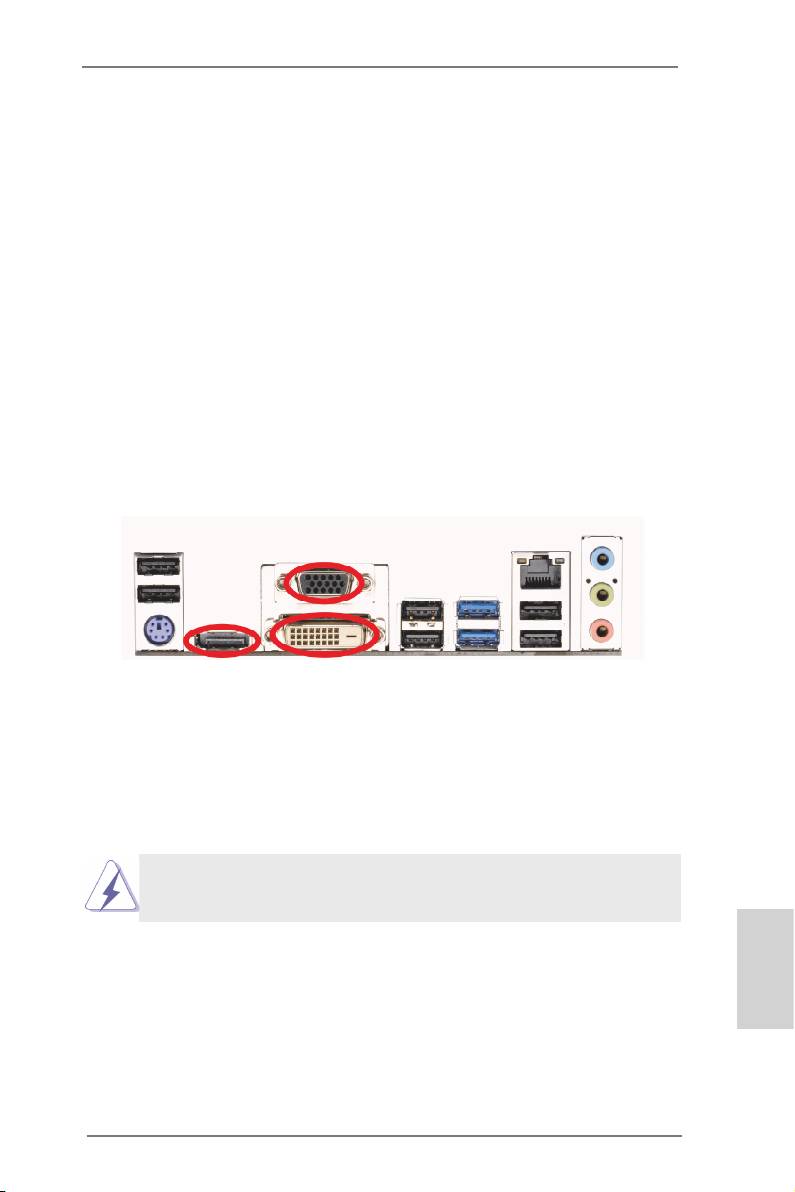
1. Connect a DVI-D monitor cable to the DVI-D port on the I/O panel, connect a
D-Sub monitor cable to the D-Sub port on the I/O panel or connect a DisplayPort
monitor cable to the DisplayPort port on the I/O panel.
D-Sub port
DisplayPort
DVI-D port
2. If you have already installed the onboard VGA driver from our support CD to your
system, you can freely enjoy the benets of dual monitor function after your
system boots. If you haven’t installed the onboard VGA driver yet, please install
the onboard VGA driver from our support CD to your system and restart your
computer.
D-Sub, DVI-D and DisplayPort monitors cannot be enabled at the same
time. You can only choose two of them.
English
23
ASRock Q77M vPro Motherboard

Surround Display Feature
This motherboard supports surround display upgrade. With the internal VGA output
support (DVI-D, D-Sub and DisplayPort) and external add-on PCI Express VGA
cards, you can easily enjoy the benets of surround display.
Please refer to the following steps to set up a surround display environment:
1. Install the PCI Express VGA cards on PCIE1 and PCIE2 slots. Please
refer to page 18 for proper expansion card installation procedures.
2. Connect a DVI-D monitor cable to the DVI-D port on the I/O panel, connect a
D-Sub monitor cable to the D-Sub port on the I/O panel, or connect an
DisplayPort monitor cable to the DisplayPort port on the I/O panel. Then connect
other monitor cables to the corresponding connectors of the add-on PCI Express
VGA cards on PCIE1 and PCIE2 slots.
3. Boot your system. Press <F2> or <Del> to enter UEFI setup. Enter “Share
Memory” option to adjust the memory capability to [32MB], [64MB], [128MB],
[256MB] or [512MB] to enable the function of D-sub. Please make sure that the
value you select is less than the total capability of the system memory. If you do
not adjust the UEFI setup, the default value of “Share Memory”, [Auto], will
disable D-Sub function when an add-on VGA card is inserted to this motherboard.
4. Install the onboard VGA driver and the add-on PCI Express VGA card driver to
your system. If you have installed the drivers already, there is no need to install
them again.
5. Set up a multi-monitor display.
®
For Windows
XP / XP 64-bit OS:
Right click on desktop, choose “Properties”, and select the “Settings” tab
so that you can adjust the parameters of the multi-monitors according to
the steps below.
A. Click the “Identify” button to display a large number on each monitor.
B. Right-click the display icon in the Display Properties dialog that you
wish to be your primary monitor, and then select “Primary”. When
you use multiple monitors with your card, one monitor will always be
Primary, and all additional monitors will be designated as Secondary.
C. Select the display icon identied by the number 2.
English
D. Click “Extend my Windows desktop onto this monitor”.
E. Right-click the display icon and select “Attached”, if necessary.
F. Set the appropriate “Screen Resolution” and “Color Quality” for the
second monitor. Click “Apply” or “OK” to apply these new values.
G. Repeat steps C through F for the display icon identied by the
numbers three to six.
24
ASRock Q77M vPro Motherboard

®
TM
TM
For Windows
7 / 7 64-bit / Vista
/ Vista
64-bit OS:
Right click the desktop, choose “Personalize”, and select the “Display
Settings” tab so that you can adjust the parameters of the multi-monitors
according to the steps below.
A. Click the number ”2” icon.
B. Click the items “This is my main monitor” and “Extend the desktop onto
this monitor”.
C. Click “OK” to save your change.
D. Repeat steps A through C for the display icons identied by the number
three to six.
6. Use Surround Display. Click and drag the display icons to positions representing
the physical setup of your monitors that you would like to use. The placement of
display icons determines how you move items from one monitor to another.
HDCP Function
HDCP function is supported on this motherboard. To use HDCP
function with this motherboard, you need to adopt a monitor
that supports HDCP function as well. Therefore, you can enjoy
the superior display quality with high-denition HDCP
encryption contents. Please refer to the instructions below for
more details about HDCP function.
What is HDCP?
HDCP stands for High-Bandwidth Digital Content Protection, a
®
specication developed by Intel
for protecting digital
entertainment content that uses the DVI interface. HDCP is a
copy protection scheme to eliminate the possibility of
intercepting digital data midstream between the video source,
or transmitter - such as a computer, DVD player or set-top box -
and the digital display, or receiver - such as a monitor, television
or projector. In other words, HDCP specication is designed to
protect the integrity of content as it is being transmitted.
Products compatible with the HDCP scheme such as DVD
players, satellite and cable HDTV set-top-boxes, as well as few
English
entertainment PCs requires a secure connection to a compliant
display. Due to the increase in manufacturers employing HDCP
in their equipment, it is highly recommended that the HDTV or
LCD monitor you purchase is compatible.
25
ASRock Q77M vPro Motherboard
2.9 ASRock Smart Remote Installation Guide
ASRock Smart Remote is only used for ASRock motherboards with a CIR header.
Please refer to the procedures below for the quick installation and usage of ASRock
Smart Remote.
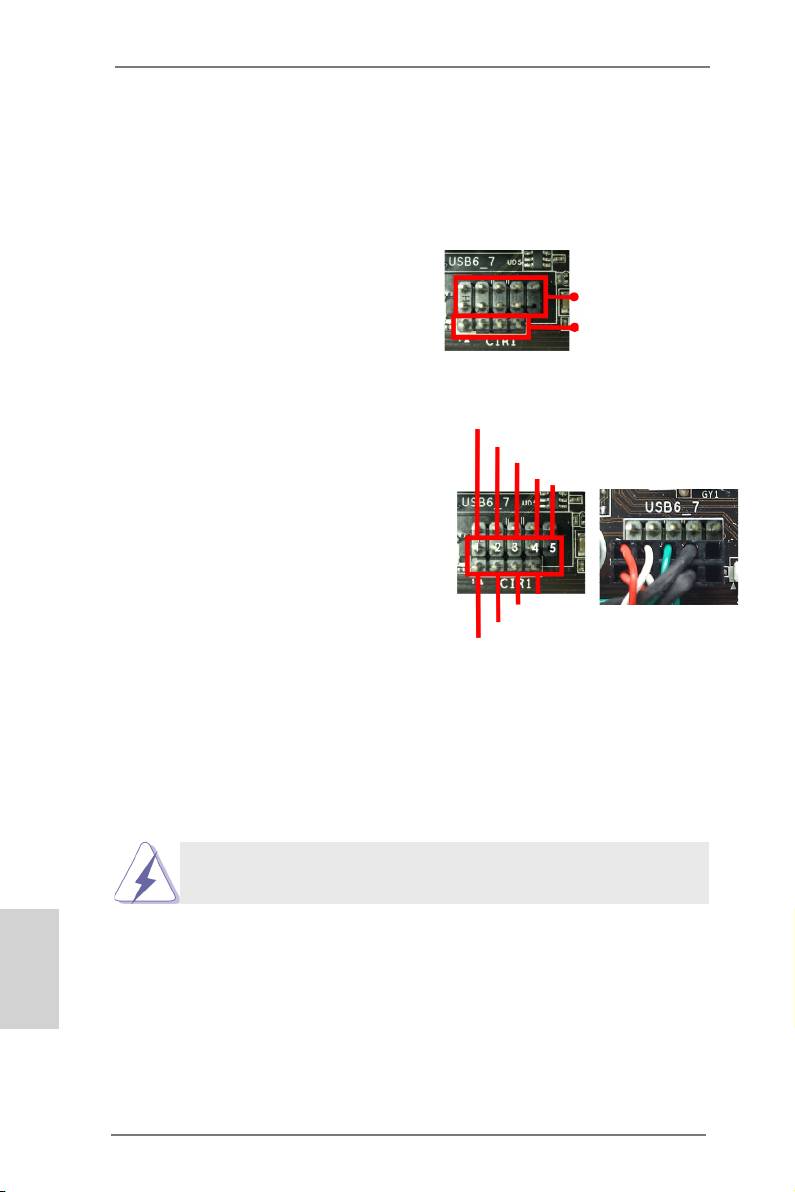
Step1. Find the CIR header located next
to the USB 2.0 header on your
USB 2.0 header (9-pin, black)
ASRock motherboard.
CIR header (4-pin, gray)
USB_PWR
Step2. Connect the front USB cable to the
P-
USB 2.0 header (as below, pin 1-5)
P+
and the CIR header. Please make
GND
DUMMY
sure the wire assignments and the
pin assignments are matched
correctly.
GND
IRTX
IRRX
ATX+5VSB
Step3. Install the Multi-Angle CIR Receiver to the front USB port.
Step4. Boot up your system. Press <F2> or <Del> to enter the BIOS Setup Utility.
Make sure the option "CIR Controller" is set to [Enabled].
(Advanced -> Super IO Conguration -> CIR Controller -> [Enabled])
If you cannot nd this option, please shut down your system and install
the Multi-Angle CIR Receiver to the other front USB port then try again.
English
Step5. Enter Windows. Execute ASRock's support CD and install the CIR Driver.
(It is listed at the bottom of driver list.)
26
ASRock Q77M vPro Motherboard
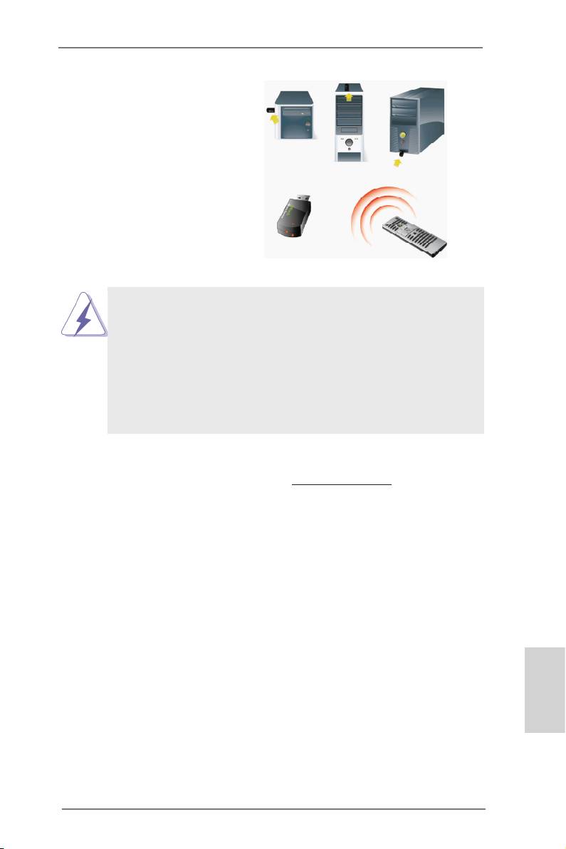
3 CIR sensors in different angles
1. Only one of the front USB ports can support CIR. When CIR is
enabled, the other ports will remain USB ports.
2. The Multi-Angle CIR Receiver is used for the front USB only.
Please do not use the rear USB bracket to connect it on the rear
panel. The Multi-Angle CIR Receiver can receive multi-directional
infrared signals (top, down and front), which is compatible with
most of the chassis on the market.
3. The Multi-Angle CIR Receiver does not support Hot-Plug. Please
install it before you boot the system.
* ASRock Smart Remote is only supported by some ASRock motherboards. Please refer to
ASRock's website for the motherboard support list: http://www.asrock.com
English
27
ASRock Q77M vPro Motherboard
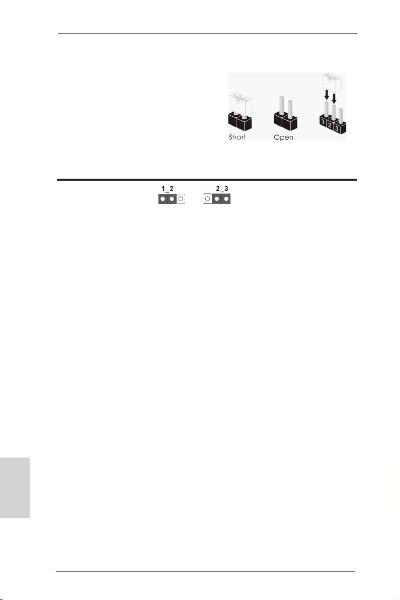
2.10 Jumpers Setup
The illustration shows how jumpers are
setup. When the jumper cap is placed on
pins, the jumper is “Short”. If no jumper cap
is placed on pins, the jumper is “Open”. The
illustration shows a 3-pin jumper whose
pin1 and pin2 are “Short” when jumper cap
is placed on these 2 pins.
Jumper Setting Description
Clear CMOS Jumper
(CLRCMOS1)
(see p.2, No. 23)
Clear CMOSDefault
Note: CLRCMOS1 allows you to clear the data in CMOS. To clear and reset the
system parameters to default setup, please turn off the computer and unplug
the power cord from the power supply. After waiting for 15 seconds, use a
jumper cap to short pin2 and pin3 on CLRCMOS1 for 5 seconds. However,
please do not clear the CMOS right after you update the BIOS. If you need
to clear the CMOS when you just nish updating the BIOS, you must boot
up the system rst, and then shut it down before you do the clear-CMOS ac-
tion. Please be noted that the password, date, time, user default prole, 1394
GUID and MAC address will be cleared only if the CMOS battery is removed.
English
28
ASRock Q77M vPro Motherboard
2.11 Onboard Headers and Connectors
Onboard headers and connectors are NOT jumpers. Do NOT place
jumper caps over these headers and connectors. Placing jumper caps
over the headers and connectors will cause permanent damage of the
motherboard!
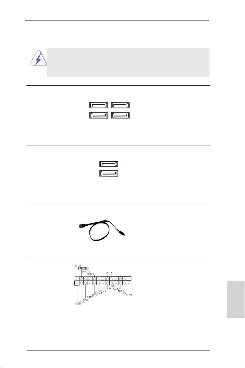
Serial ATA2 Connectors These four Serial ATA2 (SATA2)
SATA2_4 SATA2_2
(SATA2_2: see p.2, No. 16)
connectors support SATA data
(SATA2_3: see p.2, No. 19)
cables for internal storage
(SATA2_4: see p.2, No. 15)
devices. The current SATA2
SATA2_5 SATA2_3
(SATA2_5: see p.2, No. 20)
interface allows up to 3.0 Gb/s
data transfer rate.
Serial ATA3 Connectors These two Serial ATA3
SATA3_0
(SATA3_0: see p.2, No. 17)
(SATA3) connectors support
(SATA3_1: see p.2, No. 18)
SATA data cables for internal
storage devices. The current
SATA3_1
SATA3 interface allows up to 6.0
Gb/s data transfer rate.
Serial ATA (SATA) Either end of the SATA data
Data Cable cable can be connected to the
(Optional)
SATA / SATA2 / SATA3 hard
disk or the SATA2 / SATA3
connector on this motherboard.
Print Port Header This is an interface for print port
(25-pin LPT1)
cable that allows convenient
(see p.2, No. 29)
connection of printer devices.
English
29
ASRock Q77M vPro Motherboard
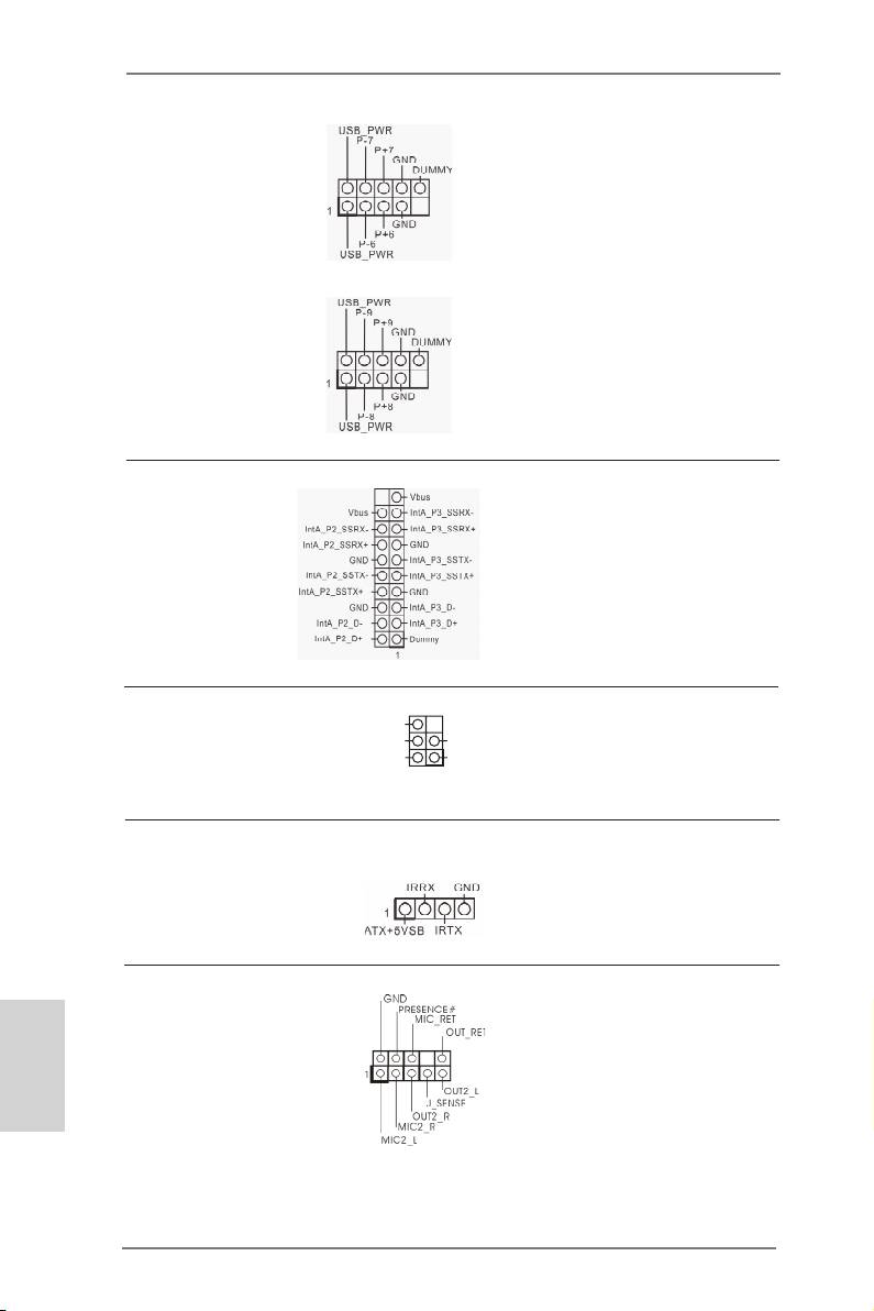
USB 2.0 Headers Besides six default USB 2.0
(9-pin USB6_7)
ports on the I/O panel, there are
(see p.2, No. 25)
two USB 2.0 headers on this
motherboard. Each USB 2.0
header can support two USB 2.0
ports.
(9-pin USB8_9)
(see p.2, No. 24)
USB 3.0 Header Besides two default USB 3.0
(19-pin USB3_2_3)
ports on the I/O panel, there is
(see p.2, No. 9)
one USB 3.0 header on this
motherboard. This USB 3.0
header can support two USB 3.0
ports.
Infrared Module Header This header supports an
DUMMY
+5VSB
GND
(5-pin IR1)
optional wireless transmitting
IRTX
IRRX
(see p.2, No. 28)
1
and receiving infrared module.
Consumer Infrared Module Header This header can be used to
(4-pin CIR1)
connect the remote controller
(see p.2, No. 26)
receiver.
Front Panel Audio Header This is an interface for front
English
(9-pin HD_AUDIO1)
panel audio cable that allows
(see p.2, No. 31)
convenient connection and
control of audio devices.
30
ASRock Q77M vPro Motherboard
1. High Denition Audio supports Jack Sensing, but the panel wire on the
chassis must support HDA to function correctly. Please follow the
instruction in our manual and chassis manual to install your system.
2. If you use AC’97 audio panel, please install it to the front panel audio
header as below:
A. Connect Mic_IN (MIC) to MIC2_L.
B. Connect Audio_R (RIN) to OUT2_R and Audio_L (LIN) to OUT2_L.
C. Connect Ground (GND) to Ground (GND).
D. MIC_RET and OUT_RET are for HD audio panel only. You don’t need
to connect them for AC’97 audio panel.
E. To activate the front mic.
®
For Windows
XP / XP 64-bit OS:
Select “Mixer”. Select “Recorder”. Then click “FrontMic”.
®
TM
TM
For Windows
7 / 7 64-bit / Vista
/ Vista
64-bit OS:
Go to the “FrontMic” Tab in the Realtek Control panel. Adjust
“Recording Volume”.
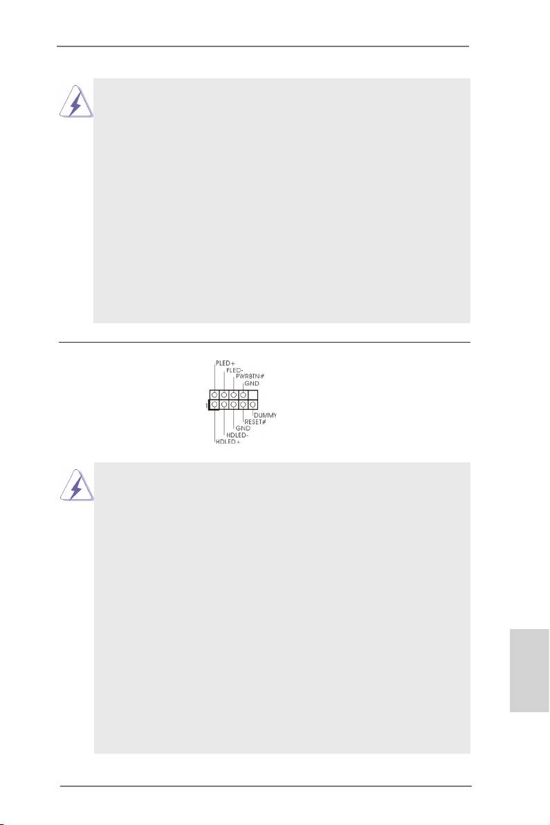
System Panel Header This header accommodates
(9-pin PANEL1)
several system front panel
(see p.2, No. 22)
functions.
Connect the power switch, reset switch and system status indicator on the
chassis to this header according to the pin assignments below. Note the
positive and negative pins before connecting the cables.
PWRBTN (Power Switch):
Connect to the power switch on the chassis front panel. You may congure
the way to turn off your system using the power switch.
RESET (Reset Switch):
Connect to the reset switch on the chassis front panel. Press the reset
switch to restart the computer if the computer freezes and fails to perform a
normal restart.
PLED (System Power LED):
Connect to the power status indicator on the chassis front panel. The LED
is on when the system is operating. The LED keeps blinking when the sys-
tem is in S1/S3 sleep state. The LED is off when the system is in S4 sleep
state or powered off (S5).
English
HDLED (Hard Drive Activity LED):
Connect to the hard drive activity LED on the chassis front panel. The LED
is on when the hard drive is reading or writing data.
31
ASRock Q77M vPro Motherboard
The front panel design may differ by chassis. A front panel module mainly
consists of power switch, reset switch, power LED, hard drive activity LED,
speaker and etc. When connecting your chassis front panel module to this
header, make sure the wire assignments and the pin assign-ments are
matched correctly.
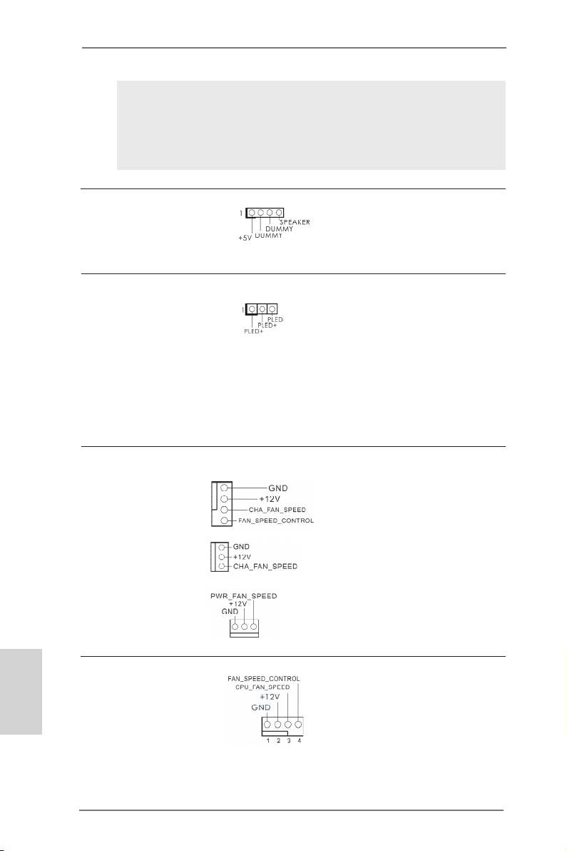
Chassis Speaker Header Please connect the chassis
(4-pin SPEAKER 1)
speaker to this header.
(see p.2, No. 14)
Power LED Header Please connect the chassis
(3-pin PLED1)
power LED to this header to
(see p.2, No. 21)
indicate system power status.
The LED is on when the system
is operating. The LED keeps
blinking in S1/S3 state. The
LED is off in S4 state or S5
state (power off).
Chassis and Power Fan Connectors Please connect the fan cables
(4-pin CHA_FAN1)
to the fan connectors and match
(see p.2, No. 13)
the black wire to the ground pin.
CHA_FAN1 and CHA_FAN2
supports Fan Control.
(3-pin CHA_FAN2)
(see p.2, No. 11)
(3-pin PWR_FAN1)
(see p.2, No. 1)
English
CPU Fan Connectors Please connect the CPU fan
(4-pin CPU_FAN1)
cable to the connector and
(see p.2, No. 4)
match the black wire to the
ground pin.
32
ASRock Q77M vPro Motherboard
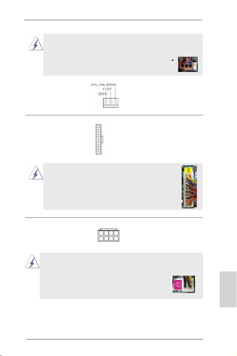
Though this motherboard provides 4-Pin CPU fan (Quiet Fan) support, the 3-Pin
CPU fan still can work successfully even without the fan speed control function.
If you plan to connect the 3-Pin CPU fan to the CPU fan connector on this
motherboard, please connect it to Pin 1-3.
Pin 1-3 Connected
3-Pin Fan Installation
(3-pin CPU_FAN2)
(see p.2, No. 5)
12
24
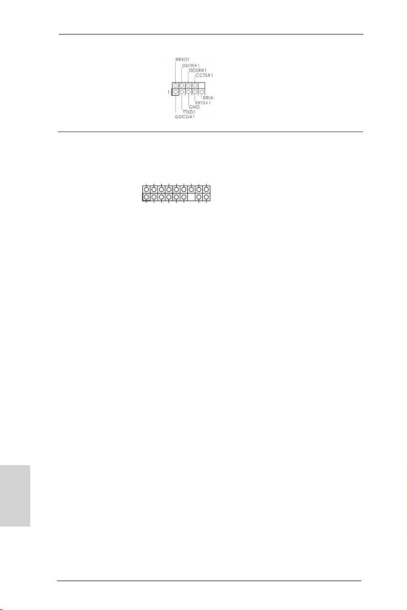
ATX Power Connector Please connect an ATX power
(24-pin ATXPWR1)
supply to this connector.
(see p.2, No. 8)
1
13
Though this motherboard provides 24-pin ATX power connector,
12
24
it can still work if you adopt a traditional 20-pin ATX power supply.
To use the 20-pin ATX power supply, please plug your
power supply along with Pin 1 and Pin 13.
20-Pin ATX Power Supply Installation
1
13
8 5
ATX 12V Power Connector Please connect an ATX 12V
(8-pin ATX12V1)
power supply to this connector.
(see p.2, No. 2)
4 1
Though this motherboard provides 8-pin ATX 12V power connector, it can still work
if you adopt a traditional 4-pin ATX 12V power supply. To use the 4-pin ATX power
supply, please plug your power supply along with Pin 1 and Pin 5.
8 5
4-Pin ATX 12V Power Supply Installation
4 1
English
33
ASRock Q77M vPro Motherboard
Serial port Header This COM1 header supports a
(9-pin COM1)
serial port module.
(see p.2, No. 30)
SMB_DATA_MAIN
SMB_CLK_MAIN
TPM Header This connector supports a
S_PWRDWN#
(17-pin TPM1)
Trusted Platform Module (TPM)
SERIRQ#
LAD2_L
LAD1_L
GND
GND
(see p.2, No. 27)
system, which can securely
store keys, digital certicates,
passwords, and data. A TPM
1
CK_33M_TPM
LFRAME#_L
TPM_RST#
LAD3_L
+3V
LAD0_L
+3VSB
GNDF_CLKRUN#
system also helps enhance
network security, protects
digital identities, and ensures
platform integrity.
English
34
ASRock Q77M vPro Motherboard

2.12 Driver Installation Guide
To install the drivers to your system, please insert the support CD into your optical
drive rst. Then, the drivers compatible to your system can be auto-detected and
listed on the support CD driver page. Please follow the order from top to bottom to
install those required drivers. Therefore, the drivers you install can work properly.
®
TM
TM
2.13 Installing Windows
7 / 7 64-bit / Vista
/ Vista
64-bit With
RAID Functions
®
TM
TM
If you want to install Windows
7 / 7 64-bit / Vista
/ Vista
64-bit on your SATA
/ SATA2 / SATA3 HDDs with RAID functions, please refer to the document at the
following path in the Support CD for detailed procedures:
..\ RAID Installation Guide
®
TM
TM
2.14 Installing Windows
7 / 7 64-bit / Vista
/ Vista
64-bit / XP /
XP 64-bit Without RAID Functions
®
TM
TM
If you want to install Windows
7 / 7 64-bit / Vista
/ Vista
64-bit / XP / XP 64-bit
OS on your SATA / SATA2 / SATA3 HDDs without RAID functions, please follow the
procedures below according to the OS you install.
®
2.14.1 Installing Windows
XP / XP 64-bit Without RAID Functions
®
If you want to install Windows
XP / XP 64-bit OS on your SATA / SATA2 / SATA3
HDDs without RAID functions, please follow the steps below.
Using SATA / SATA2 / SATA3 HDDs without NCQ function
STEP 1: Set Up UEFI.
A. Enter UEFI SETUP UTILITY Advanced screen Storage Conguration.
B. Set the option “SATA Mode Selection” to [IDE]. (For SATA2_2 to SATA2_5,
English
SATA3_0 and SATA3_1 ports.)
®
STEP 2: Install Windows
XP / XP 64-bit OS on your system.
35
ASRock Q77M vPro Motherboard

®
TM
TM
2.14.2 Installing Windows
7 / 7 64-bit / Vista
/ Vista
64-bit
Without RAID Functions
®
TM
TM
If you want to install Windows
7 / 7 64-bit / Vista
/ Vista
64-bit OS on your SATA
/ SATA2 / SATA3 HDDs without RAID functions, please follow the steps below.
Using SATA / SATA2 / SATA3 HDDs with NCQ function
STEP 1: Set Up UEFI.
A. Enter UEFI SETUP UTILITY Advanced screen Storage Conguration.
B. Set the option “SATA Mode Selection” to [AHCI]. (For SATA2_2 to SATA2_5,
SATA3_0 and SATA3_1 ports.)
®
TM
TM
STEP 2: Install Windows
7 / 7 64-bit / Vista
/ Vista
64-bit OS on your
system.
Using SATA / SATA2 / SATA3 HDDs without NCQ function
STEP 1: Set Up UEFI.
A. Enter UEFI SETUP UTILITY Advanced screen Storage Conguration.
B. Set the option “SATA Mode Selection” to [IDE]. (For SATA2_2 to SATA2_5,
SATA3_0 and SATA3_1 ports.)
®
TM
TM
STEP 2: Install Windows
7 / 7 64-bit / Vista
/ Vista
64-bit OS on your
system.
English
36
ASRock Q77M vPro Motherboard

3. BIOS Information
The Flash Memory on the motherboard stores BIOS Setup Utility. When you start up
the computer, please press <F2> or <Del> during the Power-On-Self-Test (POST)
to enter BIOS Setup utility; otherwise, POST continues with its test routines. If you
wish to enter BIOS Setup after POST, please restart the system by pressing <Ctl>
+ <Alt> + <Delete>, or pressing the reset button on the system chassis. The BIOS
Setup program is designed to be user-friendly. It is a menu-driven program, which
allows you to scroll through its various sub-menus and to select among the prede-
termined choices. For the detailed information about BIOS Setup, please refer to the
User Manual (PDF le) contained in the Support CD.
4. Software Support CD information
®
®
This motherboard supports various Microsoft
Windows
operating systems: 7 / 7
TM
TM
64-bit / Vista
/ Vista
64-bit / XP / XP 64-bit. The Support CD that came with the
motherboard contains necessary drivers and useful utilities that will enhance moth-
erboard features. To begin using the Support CD, insert the CD into your CD-ROM
drive. It will display the Main Menu automatically if “AUTORUN” is enabled in your
computer. If the Main Menu does not appear automatically, locate and double-click
on the le “ASRSETUP.EXE” in the Support CD to display the menu.
English
37
ASRock Q77M vPro Motherboard
1. Einführung
Wir danken Ihnen für den Kauf des ASRock Q77M vPro Motherboard, ein zuver-
lässiges Produkt, welches unter den ständigen, strengen Qualitätskontrollen von
ASRock gefertigt wurde. Es bietet Ihnen exzellente Leistung und robustes Design,
gemäß der Verpflichtung von ASRock zu Qualität und Halbarkeit. Diese Schnel-
linstallationsanleitung führt in das Motherboard und die schrittweise Installation
ein. Details über das Motherboard nden Sie in der Bedienungsanleitung auf der
Support-CD.
Da sich Motherboard-Spezikationen und BIOS-Software verändern können,
kann der Inhalt dieses Handbuches ebenfalls jederzeit geändert werden. Für
den Fall, dass sich Änderungen an diesem Handbuch ergeben, wird eine neue
Version auf der ASRock-Website, ohne weitere Ankündigung, verfügbar sein.
Die neuesten Grakkarten und unterstützten CPUs sind auch auf der ASRock-
Website aufgelistet.
ASRock-Website: http://www.asrock.com
Wenn Sie technische Unterstützung zu Ihrem Motherboard oder spezische
Informationen zu Ihrem Modell benötigen, besuchen Sie bitte unsere Webseite:
www.asrock.com/support/index.asp
1.1 Kartoninhalt
ASRock Q77M vPro Motherboard
(Micro ATX-Formfaktor: 24.4 cm x 24.4 cm; 9.6 Zoll x 9.6 Zoll)
ASRock Q77M vPro Schnellinstallationsanleitung
ASRock Q77M vPro Support-CD
Zwei Serial ATA (SATA) -Datenkabel (optional)
Ein I/O Shield
ASRock erinnert...
®
TM
TM
Zur besseren Leistung unter Windows
7 / 7, 64 Bit / Vista
/ Vista
64 Bit empfehlen wir, die Speicherkonguration im BIOS auf den AHCI-
Deutsch
Modus einzustellen. Hinweise zu den BIOS-Einstellungen nden Sie in
der Bedienungsanleitung auf der mitgelieferten CD.
38
ASRock Q77M vPro Motherboard
1.2 Spezifikationen
Plattform - Micro ATX-Formfaktor: 24.4 cm x 24.4 cm; 9.6 Zoll x 9.6 Zoll
- Alle Feste Kondensatordesign
®
TM
CPU - Unterstützt Intel
Core
i7- / i5- / i3-Prozessoren der 3ten
und 2ten Generation im LGA1155-Package
- 4 + 2-Stromphasendesign
®
- Unterstützt Intel
Turbo Boost 2.0-Technologie
- Unterstützt freigegebene CPU der K-Serie
(siehe VORSICHT 1)
- Unterstützt Hyper-Threading-Technologie
(siehe VORSICHT 2)
®
Chipsatz - Intel
Q77
®
TM
- Unterstützt Intel
vPro
Technologie (siehe VORSICHT 3)
®
- Unterstützt Intel
Active Management Technology 8.0
(siehe VORSICHT 4)
®
- Unterstützt Intel
Small Business Advantage
(siehe VORSICHT 5)
®
- Unterstützt Intel
Rapid Start Technology und Smart
Connect Technology
®
®
TM
* Intel
Small Business Advantage, Intel
vPro
-Technologie
®
und Intel
Active Management Technology 8.0 können nur
®
TM
TM
mit Prozessoren der Intel
Core
vPro
-Familie unterstützt
werden
Speicher - Dual-Kanal DDR3 Speichertechnologie (siehe VORSICHT 6)
- 4 x Steckplätze für DDR3
- Unterstützt DDR3 1600/1333/1066 non-ECC, ungepufferter
®
Speicher (DDR3 1600 mit Intel
Ivy Bridge-Prozessor, DDR3
®
1333 mit Intel
Sandy Bridge-Prozessor)
- Max. Kapazität des Systemspeichers: 32GB
(siehe VORSICHT 7)
®
- Unterstützt Intel
Extreme Memory Prole (XMP)1.3/1.2
Erweiterungs- - 1 x PCI Express 3.0 x16-Steckplätze (PCIE1: x16-Modus)
steckplätze (siehe VORSICHT 8)
®
* PCIE 3.0 wird nur mit Intel
Ivy Bridge-Prozessor
®
unterstützt. Mit Intel
Sandy Bridge-Prozessor wird nur
PCIE 2.0 unterstützt.
Deutsch
- 1 x PCI Express 2.0 x16-Steckplätze (PCIE2:x4-Modus)
- 2 x PCI -Steckplätze
TM
TM
TM
- Unterstützt AMD
Quad CrossFireX
und CrossFireX
®
Onboard-VGA * Integrierte Intel
HD-Grakdarstellungen und die VGA-
39
ASRock Q77M vPro Motherboard
Ausgänge können nur durch GPU-integrierte Prozessoren
unterstützt werden.
®
- Unterstützt hochauösende integrierte Intel
-Graklösungen:
®
®
TM
®
Intel
Quick-Sync-Video 2.0, Intel
InTru
3D, Intel
Clear-
®
TM
®
Video-Technik (HD), Intel
Insider
, Intel
HD Graphics
2500/4000
®
- Pixel Shader 5.0, DirectX 11 mit Intel
Ivy Bridge-Prozessor,
®
Pixel Shader 4.1, DirectX 10.1 mit Intel
Sandy Bridge-
Prozessor
- Maximal gemeinsam genutzter Speicher 1760MB
(siehe VORSICHT 9)
- Drei VGA-Ausgangsoptionen: D-Sub, DVI-D sowie
DisplayPort (siehe VORSICHT 10)
- Unterstützt DVI mit einer maximalen Auösung von 1920 x
1200 bei 60 Hz
- Unterstützt D-Sub mit einer maximalen Auösung von 2048
x 1536 bei 75 Hz
- Unterstützt DisplayPort mit einer maximalen Auösung von
2560 x 1600 bei 60 Hz
- Unterstützt HDCP-Funktion mit DVI- und DisplayPort-Ports
- Unterstutzt 1080p Blu-ray (BD) / HD-DVD-Wiedergabe mit
DVI- und DisplayPort-Ports
Audio - 5.1
CH HD Audio (Realtek ALC662 Audio Codec)
TM
- Unterstützt THX TruStudio
LAN - PCIE x1 Gigabit LAN 10/100/1000 Mb/s
®
- Intel
82579LM
- Unterstützt Wake-On-LAN
- Unterstützt energieefzientes Ethernet 802.3az
- Unterstützt PXE
E/A-Anschlüsse I/O Panel
an der Rückseite - 1 x PS/2-Tastaturanschluss
- 1 x D-Sub port
- 1 x DVI-D port
- 1 x DisplayPort
Deutsch
- 6 x Standard-USB 2.0-Anschlüsse
- 2 x Standard-USB 3.0-Anschlüsse
- 1 x RJ-45 LAN Port mit LED (ACT/LINK LED und SPEED
LED)
- HD Audiobuchse: Audio Eingang / Lautsprecher vorne /
Mikrofon
SATA3 - 2 x SATA 3-Anschlüsse (6,0 Gb/s); unterstützt RAID- (RAID 0,
40
ASRock Q77M vPro Motherboard
