ASRock E35LM1: Chapter 3: UEFI SETUP UTILITY
Chapter 3: UEFI SETUP UTILITY: ASRock E35LM1

Chapter 3: UEFI SETUP UTILITY
3.1 Introduction
This section explains how to use the UEFI SETUP UTILITY to confi gure your
system. The UEFI chip on the motherboard stores the UEFI SETUP UTILITY. You
may run the UEFI SETUP UTILITY when you start up the computer. Please press
<F2> or <Del> during the Power-On-Self-Test (POST) to enter the UEFI SETUP
UTILITY, otherwise, POST will continue with its test routines.
If you wish to enter the UEFI SETUP UTILITY after POST, restart the system by
pressing <Ctl> + <Alt> + <Delete>, or by pressing the reset button on the system
chassis. You may also restart by turning the system off and then back on.
Because the UEFI software is constantly being updated, the
following UEFI setup screens and descriptions are for reference
purpose only, and they may not exactly match what you see on
your screen.
3.1.1 UEFI Menu Bar
The top of the screen has a menu bar with the following selections:
Main To set up the system time/date information
OC Tweaker To set up overclocking features
Advanced To set up the advanced UEFI features
H/W Monitor To display current hardware status
Boot To set up the default system device to locate and load the
Operating System
Security To set up the security features
Exit To exit the current screen or the UEFI SETUP UTILITY
Use < > key or < > key to choose among the selections on the menu
bar, and then press <Enter> to get into the sub screen. You can also use the
mouse to click your required item.
28

3.1.2 Navigation Keys
Please check the following table for the function description of each navigation
key.
Navigation Key(s) Function Description
/ Moves cursor left or right to select Screens
/ Moves cursor up or down to select items
+ / - To change option for the selected items
<Tab> Switch to next function
<Enter> To bring up the selected screen
<PGUP> Go to the previous page
<PGDN> Go to the next page
<HOME> Go to the top of the screen
<END> Go to the bottom of the screen
<F1> To display the General Help Screen
<F7> Discard changes and exit the UEFI SETUP UTILITY
<F9> Load optimal default values for all the settings
<F10> Save changes and exit the UEFI SETUP UTILITY
<F12> Print screen
<ESC> Jump to the Exit Screen or exit the current screen
3.2 Main Screen
When you enter the UEFI SETUP UTILITY, the Main screen will appear and display
the system overview.
System Browser
System Browser can let you easily check your current system
confi guration in UEFI setup.
29
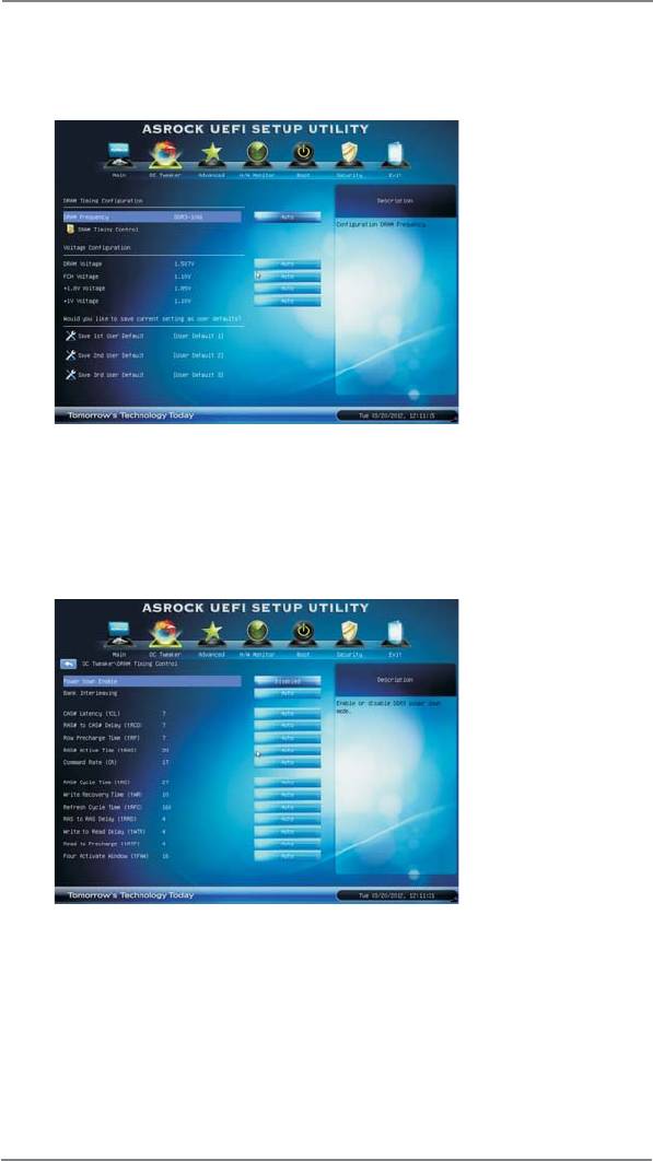
3.3 OC Tweaker Screen
In the OC Tweaker screen, you can set up overclocking features.
DRAM Timing Confi guration
DRAM Frequency
If [Auto] is selected, the motherboard will detect the memory module(s)
inserted and assigns appropriate frequency automatically.
DRAM Timing Control
Power Saving Mode
Use this to enable or disable Power Saving Mode. The default value is
[Disabled].
Bank Interleaving
Interleaving allows memory accesses to be spread out over banks on the
same node, or accross nodes, decreasing access contention.
30

CAS# Latency (tCL)
Use this item to change CAS# Latency (tCL) Auto/Manual setting. The
default is [Auto].
RAS# to CAS# Delay (tRCD)
Use this item to change RAS# to CAS# Delay (tRCD) Auto/Manual setting.
The default is [Auto].
Row Precharge Time (tRP)
Use this item to change Row Precharge Time (tRP) Auto/Manual setting.
The default is [Auto].
RAS# Active Time (tRAS)
Use this item to change RAS# Active Time (tRAS) Auto/Manual setting.
The default is [Auto].
Command Rate (CR)
Use this item to change Command Rate (CR) Auto/Manual setting. Min:
1N. Max: 2N. The default is [Auto].
RAS# Cycle Time (tRC)
Use this item to change RAS# Cycle Time (tRC) Auto/Manual setting. The
default is [Auto].
Write Recovery Time (tWR)
Use this item to change Write Recovery Time (tWR) Auto/Manual setting.
The default is [Auto].
Refresh Cycle Time (tRFC)
Use this item to change Refresh Cycle Time (tRFC) Auto/Manual setting.
The default is [Auto].
RAS to RAS Delay (tRRD)
Use this item to change RAS to RAS Delay (tRRD) Auto/Manual setting.
The default is [Auto].
Write to Read Delay (tWTR)
Use this item to change Write to Read Delay (tWTR) Auto/Manual setting.
The default is [Auto].
Read to Precharge (tRTP)
Use this item to change Read to Precharge (tRTP) Auto/Manual setting.
The default is [Auto].
Four Activate Window (tFAW)
Use this item to change Four Activate Window (tFAW) Auto/Manual
setting. The default is [Auto].
31

Voltage Confi guration
DRAM Voltage
Use this to select DRAM Voltage. The default value is [Auto].
FCH Voltage
Use this to select FCH Voltage. The default value is [Auto].
+1.8V Voltage
Use this to select +1.8V Voltage. The default value is [Auto].
+1V Voltage
Use this to select +1V Voltage. The default value is [Auto].
User Default
In this option, you are allowed to load and save three user defaults
according to your own requirements.
32

3.4 Advanced Screen
In this section, you may set the confi gurations for the following items: CPU Confi gu-
ration, North Bridge Confi guration, South Bridge Confi guration, Storage Confi gura-
tion, Super IO Confi guration, ACPI Confi guration and USB Confi guration.
Setting wrong values in this section may cause
the system to malfunction.
Instant Flash
Instant Flash is a UEFI fl ash utility embedded in Flash ROM. This conve-
nient UEFI update tool allows you to update system UEFI without enter-
®
ing operating systems fi rst like MS-DOS or Windows
. Just save the new
UEFI fi le to your USB fl ash drive, fl oppy disk or hard drive and launch this
tool, then you can update your UEFI only in a few clicks without prepar-
ing an additional fl oppy diskette or other complicated fl ash utility. Please
be noted that the USB fl ash drive or hard drive must use FAT32/16/12 fi le
system. If you execute Instant Flash utility, the utility will show the UEFI
fi les and their respective information. Select the proper UEFI fi le to up-
date your UEFI, and reboot your system after the UEFI update process is
completed.
Internet Flash
Internet Flash searches for available UEFI firmware updates from our
servers. In other words, the system can auto-detect the latest UEFI from
®
our servers and fl ash them without entering Windows
OS. Please note
that you must be running on a DHCP confi gured computer in order to en-
able this function.
33

3.4.1 CPU Configuration
Cool ‘n’ Quiet
TM
Use this item to enable or disable AMD’s Cool ‘n’ Quiet
technology. The
default value is [Enabled]. Confi guration options: [Auto], [Enabled] and
®
TM
[Disabled]. If you install Windows
7 / Vista
and want to enable this
function, please set this item to [Enabled]. Please note that enabling this
function may reduce CPU voltage and memory frequency, and lead to
system stability or compatibility issue with some memory modules or
power supplies. Please set this item to [Disable] if above issue occurs.
SVM Mode
Use this to enable or disable SVM (Secure Virtual Machine) architecture.
When this option is set to [Enabled], a VMM (Virtual Machine Architecture)
can utilize the additional hardware capabilities provided by AMD-V.
Confi guration options: [Enabled] and [Disabled]. The default value is
[Enabled].
C6 Mode
Use this to enable or disable CPU C6 state. The default value is [Disabled].
34

3.4.2 North Bridge Configuration
Primary Graphics Adapter
This item will switch the PCI Bus scanning order while searching for video
card. It allows you to select the type of Primary VGA in case of multiple
video controllers. The default value of this feature is [PCI Express].
Cofi guration options: [PCI] and [PCI Express].
Share Memory
This allows you to set onboard VGA share memory feature. The default
value is [Auto].
35

3.4.3 South Bridge Configuration
Onboard HD Audio
Select [Auto], [Enabled] or [Disabled] for the onboard HD Audio feature. If
you select [Auto], the onboard HD Audio will be disabled when PCI Sound
Card is plugged.
Front Panel
Select [Auto] or [Disabled] for the onboard HD Audio Front Panel.
Onboard LAN
This allows you to enable or disable the “Onboard LAN” feature.
Restore on AC/Power Loss
This allows you to set the power state after an unexpected AC/power loss.
If [Power Off] is selected, the AC/power remains off when the power
recovers. If [Power On] is selected, the AC/power resumes and the
system starts to boot up when the power recovers.
Good Night LED
Use this item to enable or disable Power LED and LAN LED.
36

3.4.4 Storage Configuration
SATA Controller
Use this to enable or disable SATA controller. The default value is [Enabled].
SATA Mode
Use this to select SATA mode. Confi guration options: [IDE Mode] and [AHCI
Mode]. The default value is [AHCI Mode].
AHCI (Advanced Host Controller Interface) supports NCQ
and other new features that will improve SATA disk perfor-
mance but IDE mode does not have these advantages.
Aggressive Link PM Capability
Use this item to confi gure Aggressive Link PM Capability.
Hard Disk S.M.A.R.T.
Use this item to enable or disable the S.M.A.R.T. (Self-Monitoring, Analy-
sis, and Reporting Technology) feature. Confi guration options: [Disabled]
and [Enabled].
37

3.4.5 Super IO Configuration
Serial Port
Use this item to enable or disable the onboard serial port.
Serial Port Address
Use this item to set the address for the onboard serial port. Confi guration
options: [3F8h / IRQ4] and [3E8h / IRQ4].
CIR Controller
Use this item to enable or disable CIR controller. The default value is
[Disabled].
38

3.4.6 ACPI Configuration
Suspend to RAM
Use this item to select whether to auto-detect or disable the Suspend-to-
RAM feature. Select [Auto] will enable this feature if the OS supports it.
Check Ready Bit
Use this item to enable or disable the feature Check Ready Bit.
ACPI HPET Table
Use this item to enable or disable ACPI HPET Table. The default value is
[Enabled]. Please set this option to [Enabled] if you plan to use this
®
TM
motherboard to submit Windows
Vista
certifi cation.
PS/2 Keyboard Power On
Use this item to enable or disable PS/2 keyboard to turn on the system
from the power-soft-off mode.
PCI Devices Power On
Use this item to enable or disable PCI devices to turn on the system from
the power-soft-off mode.
Ring-In Power On
Use this item to enable or disable Ring-In signals to turn on the system
from the power-soft-off mode.
RTC Alarm Power On
Use this item to enable or disable RTC (Real Time Clock) to power on the
system.
USB Keyboard/Remote Power On
Use this item to enable or disable USB Keyboard/Remote to turn on the
system from the power-soft-off mode.
USB Mouse Power On
Use this item to enable or disable USB Mouse to turn on the system from
the power-soft-off mode.
39

OMG (Online Management Guard)
Administrators are able to establish an internet curfew or restrict internet
access at specifi ed times via OMG. You may choose from [Everyday], [Day
of the week] or [Weekdays and weekends], then schedule the starting and
ending hours of internet access granted to other users. In order to prevent
users from bypassing OMG, guest accounts without permission to modify
the system time are required.
40

3.4.7 USB Configuration
USB 2.0 Controller
Use this item to enable or disable the use of USB 2.0 controller.
Legacy USB Support
Use this option to select legacy support for USB devices. There are four
confi guration options: [Enabled], [Auto], [Disabled] and [UEFI Setup Only].
The default value is [Enabled]. Please refer to below descriptions for the
details of these four options:
[Enabled] - Enables support for legacy USB.
[Auto] - Enables legacy support if USB devices are connected.
[Disabled] - USB devices are not allowed to use under legacy OS and
UEFI setup when [Disabled] is selected. If you have USB compatibility is-
sue, it is recommended to select [Disabled] to enter OS.
[UEFI Setup Only] - USB devices are allowed to use only under UEFI
setup and Windows / Linux OS.
41

3.5 Hardware Health Event Monitoring Screen
In this section, it allows you to monitor the status of the hardware on your system,
including the parameters of the CPU temperature, motherboard temperature, CPU
fan speed, chassis fan speed, and the critical voltage.
CPU Fan Setting
This allows you to set the CPU fan speed. Confi guration options: [Full On]
and [Automatic Mode]. The default is value [Full On].
Chassis Fan 1 Setting
This allows you to set the chassis fan 1 speed. Confi guration options: [Full
On] and [Manual Mode]. The default is value [Full On].
Chassis Fan 2 Setting
This allows you to set the chassis fan 2 speed. Confi guration options: [Full
On] and [Manual Mode]. The default is value [Full On].
42

3.6 Boot Screen
In this section, it will display the available devices on your system for you to confi g-
ure the boot settings and the boot priority.
Setup Prompt Timeout
This shows the number of seconds to wait for setup activation key.
65535(0XFFFF) means indefi nite waiting.
Bootup Num-Lock
If this item is set to [On], it will automatically activate the Numeric Lock
function after boot-up.
PCI ROM Priority
Use this item to adjust PCI ROM Priority. The default value is [Legacy
ROM].
Full Screen Logo
Use this item to enable or disable OEM Logo. The default value is
[Enabled].
AddOn ROM Display
Use this option to adjust AddOn ROM Display. If you enable the option
“Full Screen Logo” but you want to see the AddOn ROM information
when the system boots, please select [Enabled]. Confi guration options:
[Enabled] and [Disabled]. The default value is [Enabled].
Boot Failure Guard
Enable or disable the feature of Boot Failure Guard.
Boot Failure Guard Count
Use this item to confi gure Boot Failure Guard Count.
Boot From Onboard LAN
Use this item to enable or disable the Boot From Onboard LAN feature.
43

3.7 Security Screen
In this section, you may set or change the supervisor/user password for the system.
For the user password, you may also clear it.
44

3.6 Exit Screen
Save Changes and Exit
When you select this option, the following message “Save confi guration
changes and exit setup?” will pop-out. Select [Yes] to save the changes
and exit the UEFI SETUP UTILITY.
Discard Changes and Exit
When you select this option, the following message “Discard changes and
exit setup?” will pop-out. Select [Yes] to exit the UEFI SETUP UTILITY
without saving any changes.
Discard Changes
When you select this option, the following message “Discard changes?”
will pop-out. Select [Yes] to discard all changes.
Load UEFI Defaults
Load UEFI default values for all the setup questions. F9 key can be used
for this operation.
Launch EFI Shell from fi lesystem device
Attempts to Launch EFI Shell application (Shell64.efi) from one of the
available fi lesystem devices.
45


