ASRock E35LM1: Chapter 2: Installation
Chapter 2: Installation: ASRock E35LM1
Chapter 2: Installation
This is a Mini-ITX form factor (6.7" x 6.7", 17.0 x 17.0 cm) motherboard. Before you
install the motherboard, study the confi guration of your chassis to ensure that the
motherboard fi ts into it.
Make sure to unplug the power cord before installing or removing the
motherboard. Failure to do so may cause physical injuries to you and
damages to motherboard components.
2.1 Screw Holes
Place screws into the holes indicated by circles to secure the motherboard to the
chassis.
Do not over-tighten the screws! Doing so may damage the motherboard.
2.2 Pre-installation Precautions
Take note of the following precautions before you install motherboard components
or change any motherboard settings.
1. Unplug the power cord from the wall socket before touching any component.
2. To avoid damaging the motherboard components due to static electricity,
NEVER place your motherboard directly on the carpet or the like. Also
remember to use a grounded wrist strap or touch a safety grounded object
before you handle components.
3. Hold components by the edges and do not touch the ICs.
4. Whenever you uninstall any component, place it on a grounded antistatic pad or
in the bag that comes with the component.
Before you install or remove any component, ensure that the power is
switched off or the power cord is detached from the power supply.
Failure to do so may cause severe damage to the motherboard, peripherals,
and/or components.
14
2.3 Installation of Memory Modules (DIMM)
E35LM1 motherboard provides two 240-pin DDR3 (Double Data Rate 3) DIMM
slots.
It is not allowed to install a DDR or DDR2 memory module into DDR3
slot; otherwise, this motherboard and DIMM may be damaged.
Installing a DIMM
Please make sure to disconnect power supply before adding or
removing DIMMs or the system components.
Step 1. Unlock a DIMM slot by pressing the retaining clips outward.
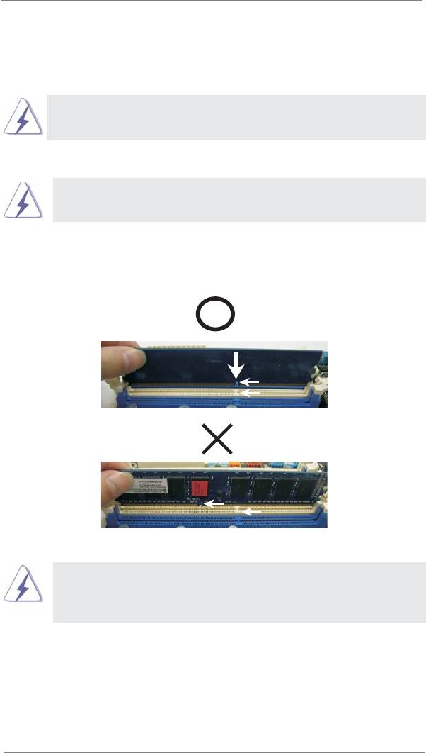
Step 2. Align a DIMM on the slot such that the notch on the DIMM matches the
break on the slot.
notch
break
notch
break
The DIMM only fi ts in one correct orientation. It will cause permanent
damage to the motherboard and the DIMM if you force the DIMM into
the slot at incorrect orientation.
Step 3. Firmly insert the DIMM into the slot until the retaining clips at both ends
fully snap back in place and the DIMM is properly seated.
15

2.4 Expansion Slot (PCI Express Slot)
There is 1 PCI Express slot on this motherboard.
PCIE slot:
PCIE1 (PCIE x16 slot; Blue) is used for PCI Express x4 lane width
graphics cards.
Installing an expansion card
Step 1. Before installing the expansion card, please make sure that the power
supply is switched off or the power cord is unplugged. Please read the
documentation of the expansion card and make necessary hardware
settings for the card before you start the installation.
Step 2. Remove the system unit cover (if your motherboard is already installed
in a chassis).
Step 3. Remove the bracket facing the slot that you intend to use. Keep the
screws for later use.
Step 4. Align the card connector with the slot and press fi rmly until the card is
completely seated on the slot.
Step 5. Fasten the card to the chassis with screws.
Step 6. Replace the system cover.
16
2.5 ASRock Smart Remote Installation Guide
ASRock Smart Remote is only used for ASRock motherboard with CIR header.
Please refer to below procedures for the quick installation and usage of ASRock
Smart Remote.
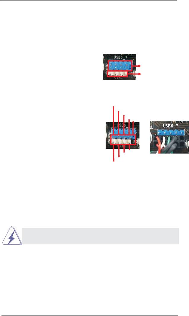
Step1. Find the CIR header located next
to the USB 2.0 header on ASRock
USB 2.0 header (9-pin, black)
motherboard.
CIR header (4-pin, gray)
USB_PWR
Step2. Connect the front USB cable to the
P-
USB 2.0 header (as below, pin 1-5)
P+
GND
and the CIR header. Please make
DUMMY
sure the wire assignments and the
pin assignments are matched
1
2
3
4
5
correctly.
GND
IRTX
IRRX
ATX+5VSB
Step3. Install
Multi-Angle CIR Receiver to the front USB port.
Step4. Boot up your system. Press <F2> or <Del> to enter BIOS Setup Utility.
Make sure the option "CIR Controller" is setting at [Enabled].
(Advanced -> Super IO Confi guration -> CIR Controller -> [Enabled])
If you cannot fi nd this option, please shut down your system and install
Multi-Angle CIR Receiver to the other front USB port then try again.
Step5. Enter Windows. Execute ASRock support CD and install CIR Driver. (It is
listed at the bottom of driver list.)
17
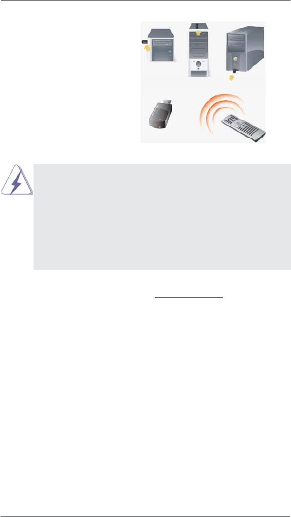
3 CIR sensors in different angles
1. Only one of the front USB port can support CIR function. When
the CIR function is enabled, the other port will remain USB
function.
2. Multi-Angle CIR Receiver
is used for front USB only. Please do
not use the rear USB bracket to connect it on the rear panel.
Multi-Angle CIR Receiver can receive the multi-direction infrared
signals (top, down and front), which is compatible with most of
the chassis on the market.
3. The Multi-Angle CIR Receiver
does not support Hot-Plug
function. Please install it before you boot the system.
* ASRock Smart Remote is only supported by some of ASRock motherboards. Please refer to
ASRock website for the motherboard support list: http://www.asrock.com
18
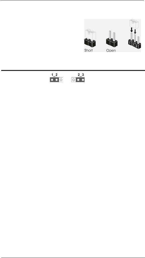
2.6 Jumpers Setup
The illustration shows how jumpers are
setup. When the jumper cap is placed on
pins, the jumper is “Short”. If no jumper cap
is placed on pins, the jumper is “Open”. The
illustration shows a 3-pin jumper whose
pin1 and pin2 are “Short” when jumper cap
is placed on these 2 pins.
Jumper Setting Description
Clear CMOS Jumper
(CLRCMOS1)
(see p.11, No. 6)
Clear CMOSDefault
Note: CLRCMOS1 allows you to clear the data in CMOS. To clear and reset the
system parameters to default setup, please turn off the computer and unplug
the power cord from the power supply. After waiting for 15 seconds, use a
jumper cap to short pin2 and pin3 on CLRCMOS1 for 5 seconds. However,
please do not clear the CMOS right after you update the BIOS. If you need
to clear the CMOS when you just fi nish updating the BIOS, you must boot
up the system fi rst, and then shut it down before you do the clear-CMOS ac-
tion. Please be noted that the password, date, time, user default profi le, 1394
GUID and MAC address will be cleared only if the CMOS battery is removed.
19
2.7 Onboard Headers and Connectors
Onboard headers and connectors are NOT jumpers. Do NOT place
jumper caps over these headers and connectors. Placing jumper caps
over the headers and connectors will cause permanent damage of the
motherboard!
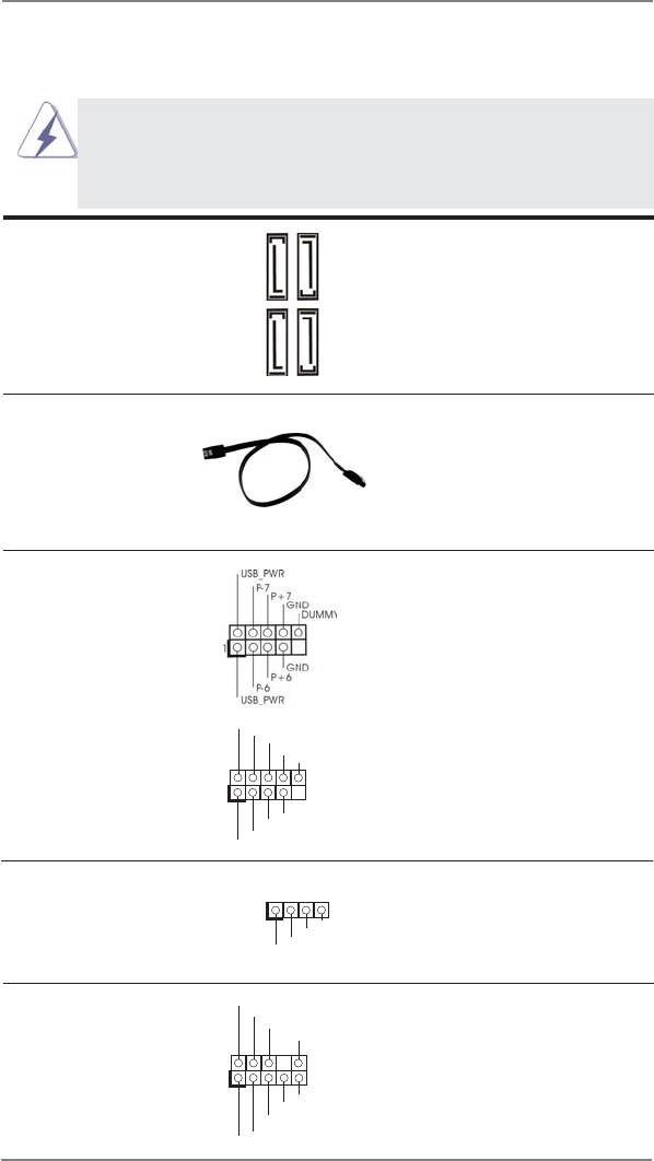
Serial ATA3 Connectors These four Serial ATA3 (SATA3)
(SATA3_1: see p.11, No. 12)
connectors support SATA data
(SATA3_2: see p.11, No. 10)
cables for internal storage
SATA3_2
SATA3_4
(SATA3_3: see p.11, No. 11)
devices. The current SATA3
(SATA3_4: see p.11, No. 9)
interface allows up to 6.0 Gb/s
data transfer rate.
SATA3_1
SATA3_3
Serial ATA (SATA) Either end of the SATA data
Data Cable cable can be connected to the
(Optional)
SATA / SATAII / SATA3 hard
disk or the SATAII / SATA3
connector on this motherboard.
USB 2.0 Headers Besides four default USB 2.0
(9-pin USB6_7)
ports on the I/O panel, there
(see p.11 No. 19)
are two USB 2.0 headers on
this motherboard. Each
USB 2.0 header can support
two USB 2.0 ports.
(9-pin USB8_9)
USB_PWR
P-9
(see p.11 No. 18)
P+9
GND
DUMMY
1
GND
P+8
P-8
USB_PWR
Consumer Infrared Module Header This header can be used to
(4-pin CIR1)
connect the remote
1
GND
(see p.11 No. 17)
controller receiver.
IRTX
IRRX
ATX+5VSB
Front Panel Audio Header This is an interface for front
GND
PRESENCE#
(9-pin HD_AUDIO1)
panel audio cable that allows
MIC_RET
OUT_RET
(see p.11 No. 20)
convenient connection and
control of audio devices.
1
OUT2_L
J_SENSE
OUT2_R
MIC2_R
MIC2_L
20
1. High Defi nition Audio supports Jack Sensing, but the panel wire on
the chassis must support HDA to function correctly. Please follow the
instruction in our manual and chassis manual to install your system.
2. If you use AC’97 audio panel, please install it to the front panel audio
header as below:
A. Connect Mic_IN (MIC) to MIC2_L.
B. Connect Audio_R (RIN) to OUT2_R and Audio_L (LIN) to OUT2_L.
C. Connect Ground (GND) to Ground (GND).
D. MIC_RET and OUT_RET are for HD audio panel only. You don’t
need to connect them for AC’97 audio panel.
E. To activate the front mic.
®
For Windows
XP / XP 64-bit OS:
Select “Mixer”. Select “Recorder”. Then click “FrontMic”.
®
TM
TM
For Windows
7 / 7 64-bit / Vista
/ Vista
64-bit OS:
Go to the "FrontMic" Tab in the Realtek Control panel. Adjust
“Recording Volume”.
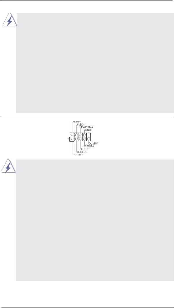
System Panel Header This header accommodates
(9-pin PANEL1)
several system front panel
(see p.11 No. 8)
functions.
Connect the power switch, reset switch and system status indicator on the
chassis to this header according to the pin assignments below. Note the
positive and negative pins before connecting the cables.
PWRBTN (Power Switch):
Connect to the power switch on the chassis front panel. You may confi gure
the way to turn off your system using the power switch.
RESET (Reset Switch):
Connect to the reset switch on the chassis front panel. Press the reset
switch to restart the computer if the computer freezes and fails to perform a
normal restart.
PLED (System Power LED):
Connect to the power status indicator on the chassis front panel. The LED
is on when the system is operating. The LED keeps blinking when the sys-
tem is in S1 sleep state. The LED is off when the system is in S3/S4 sleep
state or powered off (S5).
HDLED (Hard Drive Activity LED):
Connect to the hard drive activity LED on the chassis front panel. The LED
is on when the hard drive is reading or writing data.
21
The front panel design may differ by chassis. A front panel module mainly
consists of power switch, reset switch, power LED, hard drive activity LED,
speaker and etc. When connecting your chassis front panel module to this
header, make sure the wire assignments and the pin assign-ments are
matched correctly.
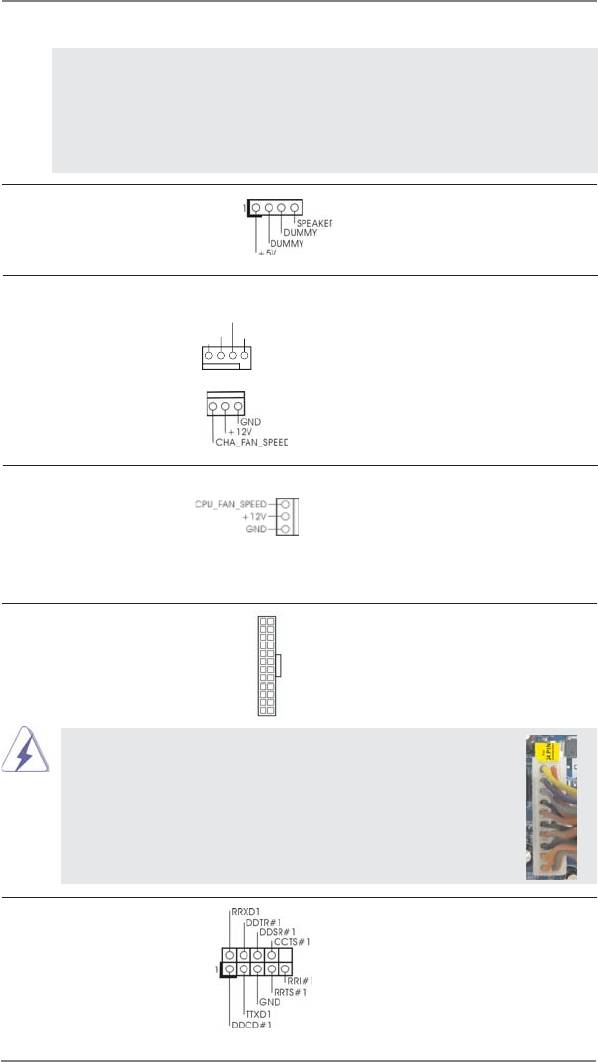
Chassis Speaker Header Please connect the chassis
(4-pin SPEAKER 1)
speaker to this header.
(see p.11 No. 13)
Chassis Fan Connectors Please connect the fan cables
(4-pin CHA_FAN1)
to the fan connectors and
CHA_FAN_SPEED
+12V
FAN_SPEED_CONTROL
(see p.11 No. 2)
match the black wire to the
GND
ground pin. CHA_FAN2
supports fan speed control by
(3-pin CHA_FAN2)
fan power voltage.
(see p.11 No. 14)
CPU Fan Connectors Please connect the CPU fan
(3-pin CPU_FAN1)
cable to the connector and
(see p.11 No. 1)
match the black wire to the
ground pin. CPU_FAN1
supports fan speed control.
ATX Power Connector Please connect an ATX power
12
24
(24-pin ATXPWR1)
supply to this connector.
(see p.11 No. 7)
1
13
Though this motherboard provides 24-pin ATX power connector,
12
24
it can still work if you adopt a traditional 20-pin ATX power supply.
To use the 20-pin ATX power supply, please plug your
power supply along with Pin 1 and Pin 13.
20-Pin ATX Power Supply Installation
1
13
Serial port Header This COM1 header supports a
(9-pin COM1)
serial port module.
(see p.11 No. 21)
22
2.8 Serial ATA3 (SATA3) Hard Disks Installation
This motherboard adopts AMD A50M chipset that supports Serial ATA3 (SATA3)
hard disks. You may install SATA3 hard disks on this motherboard for internal stor-
age devices. This section will guide you to install the SATA3 hard disks.
STEP 1: Install the SATA3 hard disks into the drive bays of your chassis.
STEP 2: Connect the SATA power cable to the SATA3 hard disk.
STEP 3: Connect one end of the SATA data cable to the motherboard’s SATA3
connector.
STEP 4: Connect the other end of the SATA data cable to the SATA3 hard disk.
2.9 Hot Plug Function for SATA3 HDDs
This motherboard supports Hot Plug function for SATA3 in AHCI mode. AMD A50M
chipset provides hardware support for Advanced Host controller Interface (AHCI), a
new programming interface for SATA host controllers developed thru a joint industry
effort.
NOTE
What is Hot Plug Function?
If the SATA3 HDDs are NOT set for RAID confi guration, it is called “Hot
Plug” for the action to insert and remove the SATA3 HDDs while the system
is still power-on and in working condition.
However, please note that it cannot perform Hot Plug if the OS has been
installed into the SATA3 HDD.
23
2.10 SATA / SATAII / SATA3 HDD Hot Plug Feature and Operation
Guide
This motherboard supports Hot Plug feature for SATA / SATAII / SATA3 HDD in
AHCI mode. Please read below operation guide of Hot Plug feature carefully. Before
you process the SATA / SATAII / SATA3 HDD Hot Plug, please check below cable
accessories from the motherboard gift box pack.
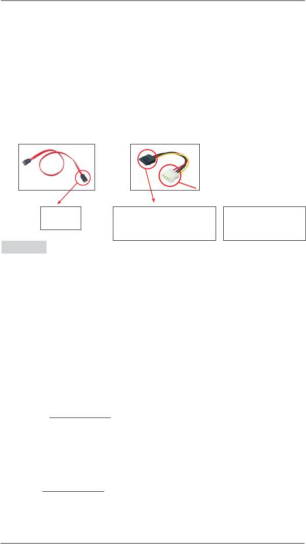
A. 7-pin SATA data cable
B. SATA power cable with SATA 15-pin power connector interface
A. SATA data cable (Red) B. SATA power cable
SATA 7-pin
The SATA 15-pin power
1x4-pin conventional
connector
connector (Black) connect
power connector (White)
to SATA / SATAII / SATA3 HDD
connect to power supply
Caution
1. Without SATA 15-pin power connector interface, the SATA / SATAII / SATA3 Hot
Plug cannot be processed.
2. Even some SATA / SATAII / SATA3 HDDs provide both SATA 15-pin power
connector and IDE 1x4-pin conventional power connector interfaces, the IDE
1x4-pin conventional power connector interface is defi nitely not able to support
Hot Plug and will cause the HDD damage and data loss.
Points of attention, before you process the Hot Plug:
1. Below operation procedure is designed only for our motherboard, which
supports SATA / SATAII / SATA3 HDD Hot Plug.
* The SATA / SATAII / SATA3 Hot Plug feature might not be supported by the
chipset because of its limitation, the SATA / SATAII / SATA3 Hot Plug support
information of our motherboard is indicated in the product spec on our
website: www.asrock.com
2. Make sure your SATA / SATAII / SATA3 HDD can support Hot Plug function from
your dealer or HDD user manual. The SATA / SATAII / SATA3 HDD, which cannot
support Hot Plug function, will be damaged under the Hot Plug operation.
3. Please make sure the SATA / SATAII / SATA3 driver is installed into system
properly. The latest SATA / SATAII / SATA3 driver is available on our support
website: www.asrock.com
4. Make sure to use the SATA power cable & data cable, which are from our
motherboard package.
5. Please follow below instructions step by step to reduce the risk of HDD crash
or data loss.
24
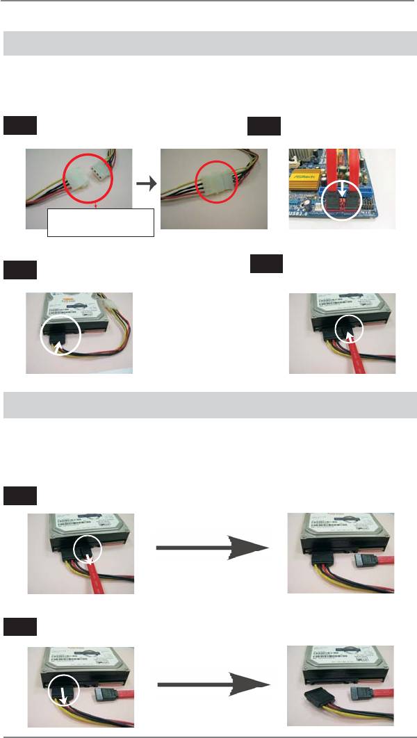
How to Hot Plug a SATA / SATAII / SATA3 HDD:
Points of attention, before you process the Hot Plug:
Please do follow below instruction sequence to process the Hot Plug, improper
procedure will cause the SATA / SATAII / SATA3 HDD damage and data loss.
Step 1
Please connect SATA power cable 1x4-pin end
Step 2
Connect SATA data cable to
(White) to the power supply 1x4-pin cable.
the motherboard’s SATAII / SATA3 connector.
SATA power cable 1x4-pin
power connector (White)
Step 4
Step 3
Connect SATA 15-pin power cable connector
Connect SATA data cable to
(Black) end to SATA / SATAII / SATA3 HDD.
the SATA / SATAII / SATA3 HDD.
How to Hot Unplug a SATA / SATAII / SATA3 HDD:
Points of attention, before you process the Hot Unplug:
Please do follow below instruction sequence to process the Hot Unplug, improper
procedure will cause the SATA / SATAII / SATA3 HDD damage and data loss.
Step 1
Unplug SATA data cable from SATA / SATAII / SATA3 HDD side.
Step 2
Unplug SATA 15-pin power cable connector (Black) from SATA / SATAII / SATA3 HDD side.
25
2.11 Driver Installation Guide
To install the drivers to your system, please insert the support CD to your optical
drive fi rst. Then, the drivers compatible to your system can be auto-detected and
listed on the support CD driver page. Please follow the order from up to bottom side
to install those required drivers. Therefore, the drivers you install can work properly.
®
TM
TM
2.12 Installing Windows
7 / 7 64-bit / Vista
/ Vista
64-bit / XP
/ XP 64-bit Without RAID Functions
®
TM
TM
If you want to install Windows
7 / 7 64-bit / Vista
/ Vista
64-bit / XP / XP 64-
bit OS on your SATA / SATAII / SATA3 HDDs without RAID functions, please follow
below procedures according to the OS you install.
®
2.12.1 Installing Windows
XP / XP 64-bit Without RAID
Functions
®
If you want to install Windows
XP / XP 64-bit OS on your SATA / SATAII / SATA3
HDDs without RAID functions, please follow below steps.
®
AHCI mode is not supported under Windows
XP / XP 64-bit OS.
Using SATA / SATAII / SATA3 HDDs without NCQ function
STEP 1: Set up UEFI.
A. Enter UEFI SETUP UTILITY Advanced screen Storage Confi guration.
B. Set the option “SATA Mode” to [IDE].
®
STEP 2: Install Windows
XP / XP 64-bit OS on your system.
®
TM
TM
2.12.2 Installing Windows
7 / 7 64-bit / Vista
/ Vista
64-bit
Without RAID Functions
®
TM
TM
If you want to install Windows
7 / 7 64-bit / Vista
/ Vista
64-bit OS on your SATA
/ SATAII / SATA3 HDDs without RAID functions, please follow below steps.
Using SATA / SATAII / SATA3 HDDs with NCQ function
STEP 1: Set up UEFI.
A. Enter UEFI SETUP UTILITY Advanced screen Storage Confi guration.
B. Set the option “SATA Mode” to [AHCI].
®
TM
TM
STEP 2: Install Windows
7 / 7 64-bit / Vista
/ Vista
64-bit OS on your
system.
26

Using SATA / SATAII / STA3 HDDs without NCQ function
STEP 1: Set up UEFI.
A. Enter UEFI SETUP UTILITY Advanced screen Storage Confi guration.
B. Set the option “SATA Mode” to [IDE].
®
TM
TM
STEP 2: Install Windows
7 / 7 64-bit / Vista
/ Vista
64-bit OS on your
system.
27


