ASRock E350M1__USB3: 2. Installation
2. Installation: ASRock E350M1__USB3
2. Installation
This is a Mini-ITX form factor (6.7" x 6.7", 17.0 x 17.0 cm) motherboard. Before you
install the motherboard, study the conguration of your chassis to ensure that the
motherboard ts into it.
Make sure to unplug the power cord before installing or removing the
motherboard. Failure to do so may cause physical injuries to you and
damages to motherboard components.
2.1 Screw Holes
Place screws into the holes indicated by circles to secure the motherboard to the
chassis.
Do not over-tighten the screws! Doing so may damage the motherboard.
2.2 Pre-installation Precautions
Take note of the following precautions before you install motherboard components
or change any motherboard settings.
1. Unplug the power cord from the wall socket before touching any component.
2. To avoid damaging the motherboard components due to static electricity,
NEVER place your motherboard directly on the carpet or the like. Also
remember to use a grounded wrist strap or touch a safety grounded object
before you handle components.
3. Hold components by the edges and do not touch the ICs.
4. Whenever you uninstall any component, place it on a grounded antistatic pad or
in the bag that comes with the component.
Before you install or remove any component, ensure that the power is
switched off or the power cord is detached from the power supply.
Failure to do so may cause severe damage to the motherboard, peripherals,
and/or components.
English
10
ASRock E350M1/USB3 Motherboard
2.3 Installation of Memory Modules (DIMM)
E350M1/USB3 motherboard provides two 240-pin DDR3 (Double Data Rate 3)
DIMM slots.
It is not allowed to install a DDR or DDR2 memory module into DDR3
slot; otherwise, this motherboard and DIMM may be damaged.
Installing a DIMM
Please make sure to disconnect power supply before adding or
removing DIMMs or the system components.
Step 1. Unlock a DIMM slot by pressing the retaining clips outward.
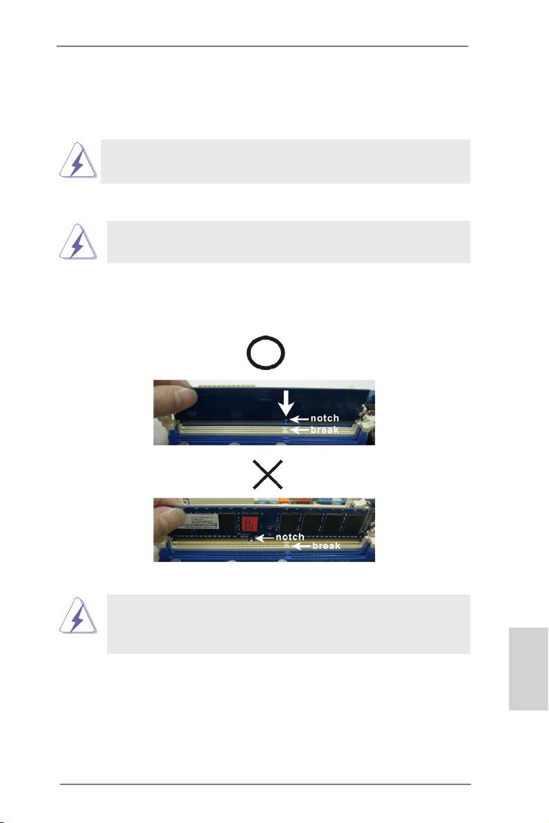
Step 2. Align a DIMM on the slot such that the notch on the DIMM matches the
break on the slot.
The DIMM only ts in one correct orientation. It will cause permanent
damage to the motherboard and the DIMM if you force the DIMM into
the slot at incorrect orientation.
Step 3. Firmly insert the DIMM into the slot until the retaining clips at both ends
fully snap back in place and the DIMM is properly seated.
English
11
ASRock E350M1/USB3 Motherboard

2.4 Expansion Slot (PCI Express Slot)
There is 1 PCI Express slot on this motherboard.
PCIE slot:
PCIE1 (PCIE x16 slot; Blue) is used for PCI Express x4 lane width
graphics cards.
Installing an expansion card
Step 1. Before installing the expansion card, please make sure that the power
supply is switched off or the power cord is unplugged. Please read the
documentation of the expansion card and make necessary hardware
settings for the card before you start the installation.
Step 2. Remove the system unit cover (if your motherboard is already installed
in a chassis).
Step 3. Remove the bracket facing the slot that you intend to use. Keep the
screws for later use.
Step 4. Align the card connector with the slot and press rmly until the card is
completely seated on the slot.
Step 5. Fasten the card to the chassis with screws.
Step 6. Replace the system cover.
English
12
ASRock E350M1/USB3 Motherboard
2.5 Dual Monitor Feature
Dual Monitor Feature
This motherboard supports dual monitor feature. With the internal VGA output
support (DVI-D, D-Sub and HDMI), you can easily enjoy the benets of dual monitor
feature without installing any add-on VGA card to this motherboard. This
motherboard also provides independent display controllers for DVI-D, D-Sub and
HDMI to support dual VGA output so that DVI-D, D-sub and HDMI can drive same
or different display contents.
To enable dual monitor feature, please follow the below steps:
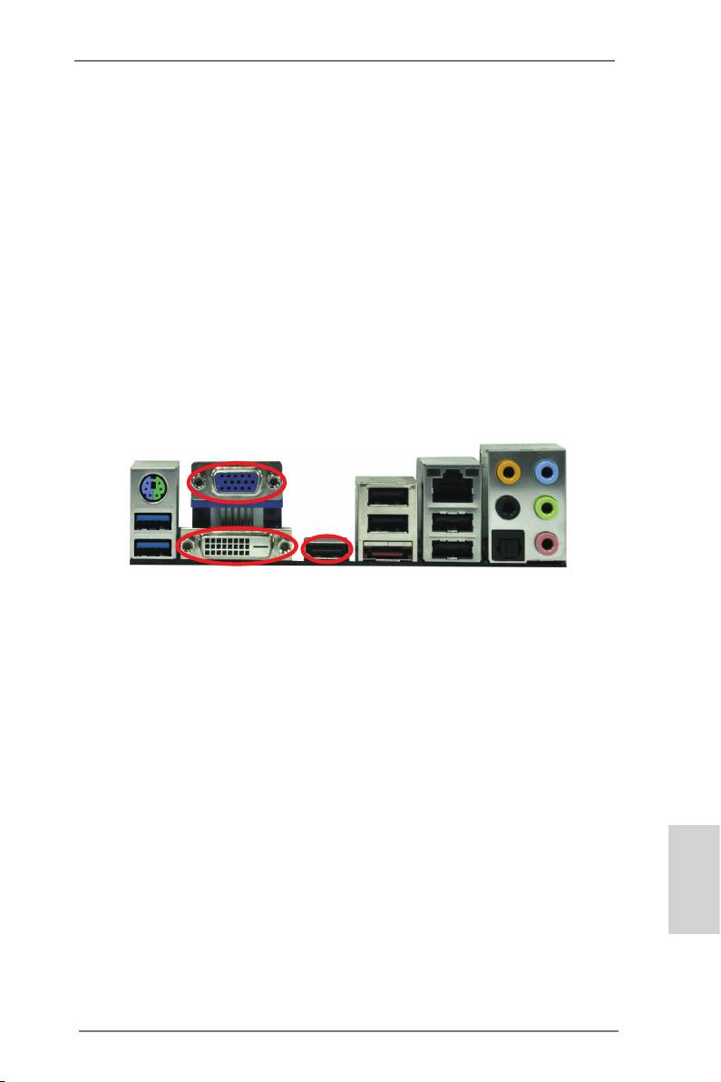
1. Connect DVI-D monitor cable to VGA/DVI-D port on the I/O panel, connect D-Sub
monitor cable to VGA/D-Sub port on the I/O panel, or connect HDMI monitor
cable to HDMI port on the I/O panel.
VGA/D-Sub port
VGA/DVI-D port
HDMI port
English
13
ASRock E350M1/USB3 Motherboard
2. If you have installed onboard VGA driver from our support CD to your system
already, you can freely enjoy the benets of dual monitor function after your
system boots. If you haven’t installed onboard VGA driver yet, please install
onboard VGA driver from our support CD to your system and restart your
computer.
D-Sub, DVI-D and HDMI monitors cannot be enabled at the same time.
You can only choose the combination: DVI-D + HDMI, DVI-D + D-Sub,
or HDMI + D-Sub.
English
14
ASRock E350M1/USB3 Motherboard

HDCP Function
HDCP function is supported on this motherboard. To use HDCP
function with this motherboard, you need to adopt the monitor
that supports HDCP function as well. Therefore, you can enjoy
the superior display quality with high-denition HDCP
encryption contents. Please refer to below instruction for more
details about HDCP function.
What is HDCP?
HDCP stands for High-Bandwidth Digital Content Protection,
®
a specication developed by Intel
for protecting digital
entertainment content that uses the DVI interface. HDCP is a
copy protection scheme to eliminate the possibility of
intercepting digital data midstream between the video source,
or transmitter - such as a computer, DVD player or set-top box -
and the digital display, or receiver - such as a monitor, television
or projector. In other words, HDCP specication is designed to
protect the integrity of content as it is being transmitted.
Products compatible with the HDCP scheme such as DVD
players, satellite and cable HDTV set-top-boxes, as well as few
entertainment PCs requires a secure connection to a compliant
display. Due to the increase in manufacturers employing HDCP
in their equipment, it is highly recommended that the HDTV or
LCD monitor you purchase is compatible.
English
15
ASRock E350M1/USB3 Motherboard
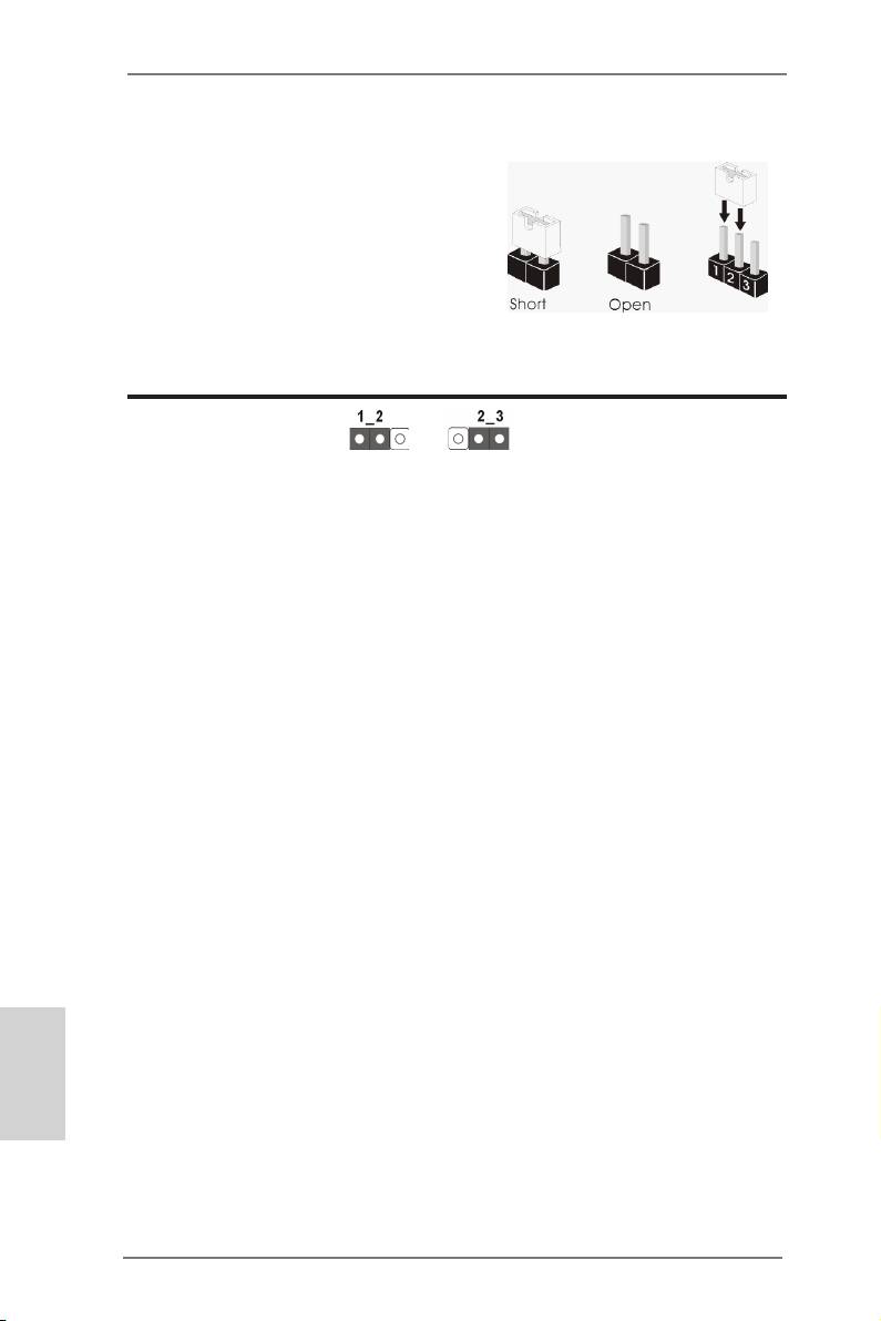
2.6 Jumpers Setup
The illustration shows how jumpers are
setup. When the jumper cap is placed on
pins, the jumper is “Short”. If no jumper cap
is placed on pins, the jumper is “Open”. The
illustration shows a 3-pin jumper whose
pin1 and pin2 are “Short” when jumper cap
is placed on these 2 pins.
Jumper Setting Description
Clear CMOS Jumper
(CLRCMOS1)
(see p.2, No. 6)
Clear CMOSDefault
Note: CLRCMOS1 allows you to clear the data in CMOS. To clear and reset the
system parameters to default setup, please turn off the computer and unplug
the power cord from the power supply. After waiting for 15 seconds, use a
jumper cap to short pin2 and pin3 on CLRCMOS1 for 5 seconds. However,
please do not clear the CMOS right after you update the BIOS. If you need
to clear the CMOS when you just nish updating the BIOS, you must boot
up the system rst, and then shut it down before you do the clear-CMOS ac-
tion. Please be noted that the password, date, time, user default prole, 1394
GUID and MAC address will be cleared only if the CMOS battery is removed.
English
16
ASRock E350M1/USB3 Motherboard
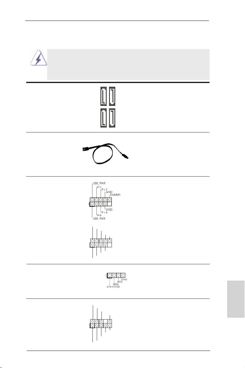
2.7 Onboard Headers and Connectors
Onboard headers and connectors are NOT jumpers. Do NOT place
jumper caps over these headers and connectors. Placing jumper caps
over the headers and connectors will cause permanent damage of the
motherboard!
Serial ATA3 Connectors These four Serial ATA3 (SATA3)
(SATA3_1: see p.2, No. 12)
connectors support SATA data
(SATA3_2: see p.2, No. 10)
cables for internal storage
SATA3_2
SATA3_4
(SATA3_3: see p.2, No. 11)
devices. The current SATA3
(SATA3_4: see p.2, No. 9)
interface allows up to 6.0 Gb/s
data transfer rate.
SATA3_1
SATA3_3
Serial ATA (SATA) Either end of the SATA data
Data Cable cable can be connected to the
(Optional)
SATA / SATAII / SATA3 hard
disk or the SATAII / SATA3
connector on this motherboard.
USB 2.0 Headers Besides four default USB 2.0
(9-pin USB6_7)
ports on the I/O panel, there
(see p.2 No. 19)
are two USB 2.0 headers on
this motherboard. Each
USB 2.0 header can support
two USB 2.0 ports.
(9-pin USB8_9)
U SB_PWR
P-9
(see p.2 No. 18)
P +9
GND
DUMMY
1
GND
P +8
P-8
U SB_PWR
Consumer Infrared Module Header This header can be used to
(4-pin CIR1)
connect the remote controller
(see p.2 No. 17)
receiver. Please refer to p. 144
for details.
Front Panel Audio Header This is an interface for front
GND
P RESENCE#
English
(9-pin HD_AUDIO1)
M IC_RET
panel audio cable that allows
OUT_RET
(see p.2 No. 20)
convenient connection and
control of audio devices.
1
O UT2_L
J _SENSE
O UT2_R
M IC2_R
M IC2_L
17
ASRock E350M1/USB3 Motherboard
1. High Denition Audio supports Jack Sensing, but the panel wire on
the chassis must support HDA to function correctly. Please follow the
instruction in our manual and chassis manual to install your system.
2. If you use AC’97 audio panel, please install it to the front panel audio
header as below:
A. Connect Mic_IN (MIC) to MIC2_L.
B. Connect Audio_R (RIN) to OUT2_R and Audio_L (LIN) to OUT2_L.
C. Connect Ground (GND) to Ground (GND).
D. MIC_RET and OUT_RET are for HD audio panel only. You don’t
need to connect them for AC’97 audio panel.
E. To activate the front mic.
®
For Windows
XP / XP 64-bit OS:
Select “Mixer”. Select “Recorder”. Then click “FrontMic”.
®
TM
TM
For Windows
8 / 8 64-bit / 7 / 7 64-bit / Vista
/ Vista
64-bit OS:
Go to the “FrontMic” Tab in the Realtek Control panel. Adjust
“Recording Volume”.
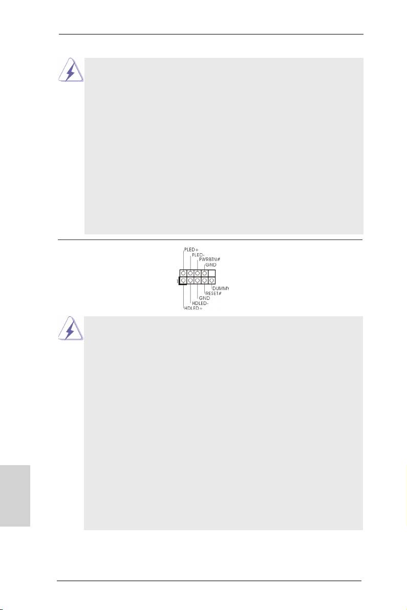
System Panel Header This header accommodates
(9-pin PANEL1)
several system front panel
(see p.2 No. 8)
functions.
Connect the power switch, reset switch and system status indicator on the
chassis to this header according to the pin assignments below. Note the
positive and negative pins before connecting the cables.
PWRBTN (Power Switch):
Connect to the power switch on the chassis front panel. You may congure
the way to turn off your system using the power switch.
RESET (Reset Switch):
Connect to the reset switch on the chassis front panel. Press the reset
switch to restart the computer if the computer freezes and fails to perform a
normal restart.
PLED (System Power LED):
Connect to the power status indicator on the chassis front panel. The LED
is on when the system is operating. The LED keeps blinking when the sys-
English
tem is in S1 sleep state. The LED is off when the system is in S3/S4 sleep
state or powered off (S5).
HDLED (Hard Drive Activity LED):
Connect to the hard drive activity LED on the chassis front panel. The LED
is on when the hard drive is reading or writing data.
18
ASRock E350M1/USB3 Motherboard
The front panel design may differ by chassis. A front panel module mainly
consists of power switch, reset switch, power LED, hard drive activity LED,
speaker and etc. When connecting your chassis front panel module to this
header, make sure the wire assignments and the pin assign-ments are
matched correctly.
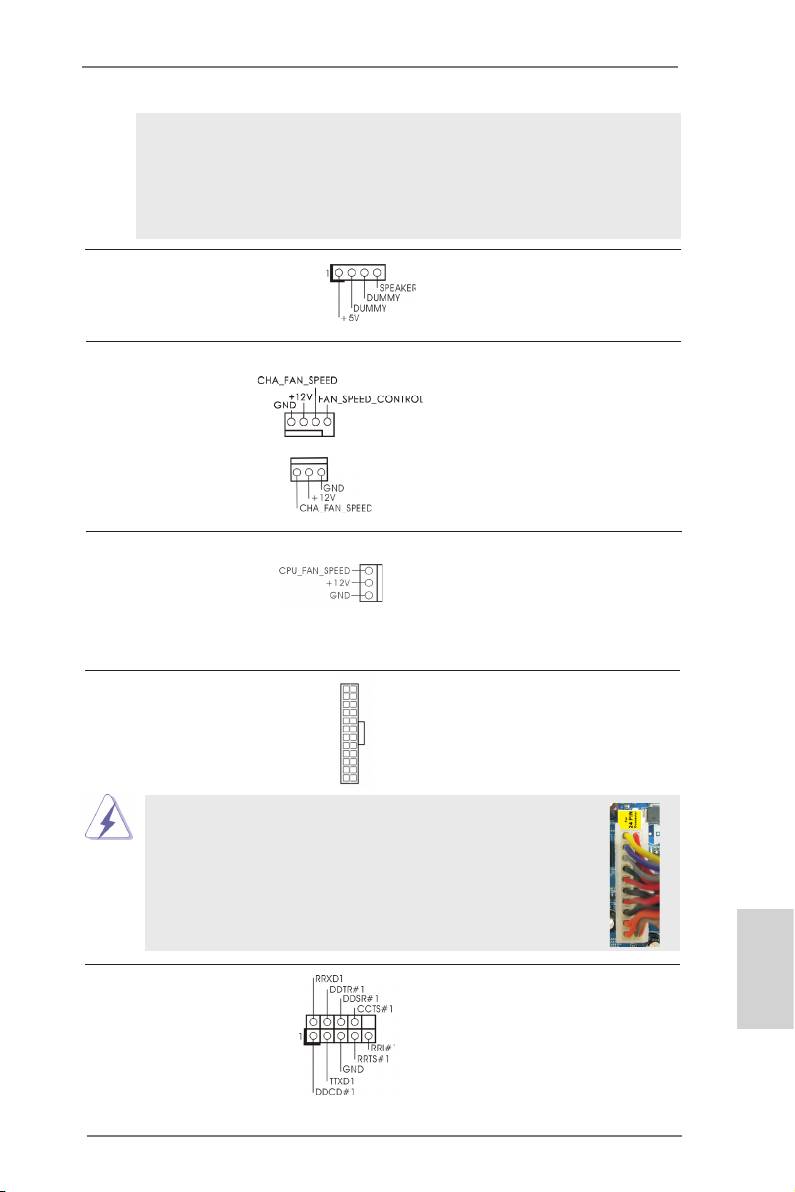
Chassis Speaker Header Please connect the chassis
(4-pin SPEAKER 1)
speaker to this header.
(see p.2 No. 13)
Chassis Fan Connectors Please connect the fan cables
(4-pin CHA_FAN1)
to the fan connectors and
(see p.2 No. 2)
match the black wire to the
ground pin. CHA_FAN2
supports fan speed control by
(3-pin CHA_FAN2)
fan power voltage.
(see p.2 No. 14)
CPU Fan Connectors Please connect the CPU fan
(3-pin CPU_FAN1)
cable to the connector and
(see p.2 No. 1)
match the black wire to the
ground pin. CPU_FAN1
supports fan speed control.
12
24
ATX Power Connector Please connect an ATX power
(24-pin ATXPWR1)
supply to this connector.
(see p.2 No. 7)
1
13
Though this motherboard provides 24-pin ATX power connector,
12
24
it can still work if you adopt a traditional 20-pin ATX power supply.
To use the 20-pin ATX power supply, please plug your
power supply along with Pin 1 and Pin 13.
20-Pin ATX Power Supply Installation
1
13
Serial port Header This COM1 header supports a
English
(9-pin COM1)
serial port module.
(see p.2 No. 21)
19
ASRock E350M1/USB3 Motherboard
2.8 Driver Installation Guide
To install the drivers to your system, please insert the support CD to your optical
drive rst. Then, the drivers compatible to your system can be auto-detected and
listed on the support CD driver page. Please follow the order from up to bottom side
to install those required drivers. Therefore, the drivers you install can work properly.
®
TM
2.9 Installing Windows
8 / 8 64-bit / 7 / 7 64-bit / Vista
/
TM
Vista
64-bit / XP / XP 64-bit Without RAID Functions
®
TM
TM
If you want to install Windows
8 / 8 64-bit / 7 / 7 64-bit / Vista
/ Vista
64-bit / XP
/ XP 64-bit OS on your SATA / SATAII / SATA3 HDDs without RAID functions, please
follow below procedures according to the OS you install.
®
2.9.1 Installing Windows
XP / XP 64-bit Without RAID
Functions
®
If you want to install Windows
XP / XP 64-bit OS on your SATA / SATAII / SATA3
HDDs without RAID functions, please follow below steps.
®
AHCI mode is not supported under Windows
XP / XP 64-bit OS.
Using SATA / SATAII / SATA3 HDDs without NCQ function
STEP 1: Set up UEFI.
A. Enter UEFI SETUP UTILITY Advanced screen Storage Conguration.
B. Set the option “SATA Mode” to [IDE].
®
STEP 2: Install Windows
XP / XP 64-bit OS on your system.
®
TM
2.9.2 Installing Windows
8 / 8 64-bit / 7 / 7 64-bit / Vista
/
TM
Vista
64-bit Without RAID Functions
®
TM
TM
If you want to install Windows
8 / 8 64-bit / 7 / 7 64-bit / Vista
/ Vista
64-bit OS
on your SATA / SATAII / SATA3 HDDs without RAID functions, please follow below
English
steps.
Using SATA / SATAII / SATA3 HDDs with NCQ function
STEP 1: Set up UEFI.
A. Enter UEFI SETUP UTILITY Advanced screen Storage Conguration.
B. Set the option “SATA Mode” to [AHCI].
®
TM
TM
STEP 2: Install Windows
8 / 8 64-bit / 7 / 7 64-bit / Vista
/ Vista
64-bit OS on
your system.
20
ASRock E350M1/USB3 Motherboard

Using SATA / SATAII / STA3 HDDs without NCQ function
STEP 1: Set up UEFI.
A. Enter UEFI SETUP UTILITY Advanced screen Storage Conguration.
B. Set the option “SATA Mode” to [IDE].
®
TM
TM
STEP 2: Install Windows
8 / 8 64-bit / 7 / 7 64-bit / Vista
/ Vista
64-bit OS on
your system.
English
21
ASRock E350M1/USB3 Motherboard
Оглавление
- Motherboard Layout
- I/O Panel
- 1. Introduction
- 2. Installation
- 3. BIOS Information
- 1. Einführung
- 2. BIOS-Information
- 1. Introduction
- 2. Informations sur le BIOS
- 1. Introduzione
- 2. Informazioni sul BIOS
- 1. Introducción
- 2. BIOS Información
- 1. Введение
- 2. Информация о BIOS
- 1. Introdução
- 2. Informações da BIOS
- 1. Giriş
- 2. BIOS Bilgileri
- 1. 제품소개
- 2. 시스템 바이오스 정보
- 1. 主板簡介
- 2. BIOS 信息
- 1. 主機板簡介
- 2. BIOS 訊息
- Installing OS on a HDD Larger Than 2TB
- Remote Receiver Installation Guide
