ASRock 990fx extreme9: 2. Installation
2. Installation: ASRock 990fx extreme9

2. Installation
This is an ATX form factor motherboard. Before you install the motherboard, study
the conguration of your chassis to ensure that the motherboard ts into it.
Pre-installation Precautions
Take note of the following precautions before you install motherboard
components or change any motherboard settings.
Before you install or remove any component, ensure that the
power is switched off or the power cord is detached from the
power supply. Failure to do so may cause severe damage to the
motherboard, peripherals, and/or components.
1. Unplug the power cord from the wall socket before touching any
component.
2. To avoid damaging the motherboard components due to static elec-
tricity, NEVER place your motherboard directly on the carpet or the
like. Also remember to use a grounded wrist strap or touch a safety
grounded object before you handle components.
3. Hold components by the edges and do not touch the ICs.
4. Whenever you uninstall any component, place it on a grounded anti-
static pad or in the bag that comes with the component.
5. When placing screws into the screw holes to secure the mother-
board to the chassis, please do not over-tighten the screws! Doing
so may damage the motherboard.
17
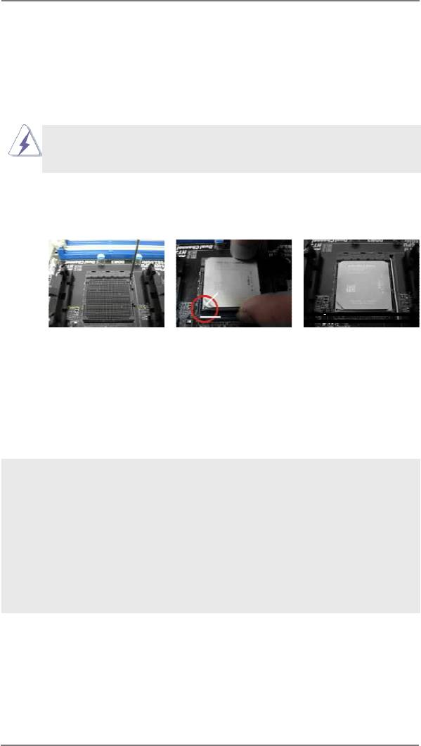
2.1 CPU Installation
o
Step 1. Unlock the socket by lifting the lever up to a 90
angle.
Step 2. Position the CPU directly above the socket such that the CPU corner with
the golden triangle matches the socket corner with a small triangle.
Step 3. Carefully insert the CPU into the socket until it ts in place.
The CPU ts only in one correct orientation. DO NOT force the CPU
into the socket to avoid bending of the pins.
Step 4. When the CPU is in place, press it rmly on the socket while you push
down the socket lever to secure the CPU. The lever clicks on the side tab
to indicate that it is locked.
Lever 90° Up
CPU Golden Triangle
Socker Corner
Small Triangle
STEP 1:
STEP 2 / STEP 3:
STEP 4:
Lift Up The Socket Lever
Match The CPU Golden Triangle
Push Down And Lock
To The Socket Corner Small
The Socket Lever
Triangle
2.2 Installation of CPU Fan and Heatsink
After you install the CPU into this motherboard, it is necessary to install a
larger heatsink and cooling fan to dissipate heat. You also need to spray
thermal grease between the CPU and the heatsink to improve heat dis-
sipation. Make sure that the CPU and the heatsink are securely fastened
and in good contact with each other. Then connect the CPU fan to the
CPU FAN connector (CPU_FAN1, see Page 14, No. 4 or CPU_FAN2,
see Page 14, No. 5). For proper installation, please kindly refer to the
instruction manuals of the CPU fan and the heatsink.
18
2.3 Installation of Memory Modules (DIMM)
This motherboard provides four 240-pin DDR3 (Double Data Rate 3) DIMM slots,
and supports Dual Channel Memory Technology. For dual channel conguration,
you always need to install identical (the same brand, speed, size and chip-type)
DDR3 DIMM pair in the slots. In other words, you have to install identical DDR3
DIMM pair in Dual Channel (DDR3_A1 and DDR3_B1; see p.14 No.7) or identical
DDR3 DIMM pair in Dual Channel (DDR3_A2 and DDR3_B2; see p.14 No.8), so
that Dual Channel Memory Technology can be activated. This motherboard also
allows you to install four DDR3 DIMMs for dual channel conguration, and please
install identical DDR3 DIMMs in all four slots. You may refer to the Dual Channel
Memory Conguration Table below.
Dual Channel Memory Congurations
DDR3_A1 DDR3_A2 DDR3_B1 DDR3_B2
(Black Slot) (Black Slot) (Black Slot) (Black Slot)
(1) - Populated - Populated
(2) Populated - Populated -
(3)* Populated Populated Populated Populated
* For the conguration (3), please install identical DDR3 DIMMs in all four
slots.
1. Please install the memory module into DDR3_A2 and DDR3_B2
slots for the rst priority.
2. If you want to install two memory modules, for optimal compatibility
and reliability, it is recommended to install them either in the set
of DDR3_A1 and DDR3_B1 slots, or in the set of DDR3_A2 and
DDR3_B2 slots.
3. If only one memory module or three memory modules are installed
in the DDR3 DIMM slots on this motherboard, it is unable to activate
the Dual Channel Memory Technology.
4. If a pair of memory modules is NOT installed in the same Dual
Channel, for example, installing a pair of memory modules in
DDR3_A1 and DDR3_A2, it is unable to activate the Dual Channel
Memory Technology .
5. It is not allowed to install a DDR or DDR2 memory module into
DDR3 slot; otherwise, this motherboard and DIMM may be dam-
aged.
6. If you adopt DDR3 2450/2100 memory modules on this mother-
board, it is recommended to install them on DDR3_A2 and DDR3_
B2 slots.
19
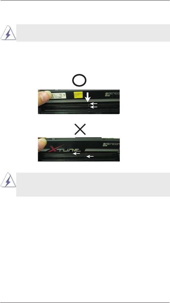
Installing a DIMM
Please make sure to disconnect power supply before adding or
removing DIMMs or the system components.
Step 1. Unlock a DIMM slot by pressing the retaining clips outward.
Step 2. Align a DIMM on the slot such that the notch on the DIMM matches the
break on the slot.
notch
break
notch
break
The DIMM only ts in one correct orientation. It will cause permanent
damage to the motherboard and the DIMM if you force the DIMM into
the slot at incorrect orientation.
Step 3. Firmly insert the DIMM into the slot until the retaining clips at both ends
fully snap back in place and the DIMM is properly seated.
20
2.4 Expansion Slots (PCI and PCI Express Slots)
There is 1 PCI slot and 5 PCI Express slots on this motherboard.
PCI Slot: PCI slot is used to install expansion cards that have the 32-bit PCI
interface.
PCIE Slots:
PCIE1 (PCIE x16 slot) is used for PCI Express x16 lane width graphics
cards.
PCIE2 (PCIE x1 slot) is used for PCI Express cards with x1 lane width
cards, such as ASRock Game Blaster, Gigabit LAN card, SATA card.
PCIE3 (PCIE x16 slot) is used for PCI Express x4 lane width graphics
cards.
PCIE4 (PCIE x16 slot) is used for PCI Express x16 lane width graphics
cards.
PCIE5 (PCIE x16 slot) is used for PCI Express x8 lane width graphics
cards.
PCIE Slot Congurations
PCIE1 PCIE2 PCIE3 PCIE4 PCIE5
Single Graphics Card x16 N/A N/A N/A N/A
Two Graphics Cards in x16 N/A N/A x16 N/A
TM
TM
CrossFireX
or SLI
Mode
Three Graphics Cards in x16 N/A N/A x8 x8
TM
3-Way CrossFireX
or
TM
3-Way SLI
Mode
1. In single VGA card mode, it is recommended to install a PCI Express
x16 graphics card in the PCIE1 slot.
TM
TM
2. In CrossFireX
mode or SLI
mode, please install the PCI Express
x16 graphics cards in PCIE1 and PCIE4 slots. Both these two slots
will work at x16 bandwidth.
TM
TM
3. In 3-Way CrossFireX
mode or 3-Way SLI
mode, please install the
PCI Express x16 graphics cards in PCIE1, PCIE4 and PCIE5 slots.
PCIE1 will work at x16 bandwidth, while PCIE4 and PCIE5 slots will
work at x8 bandwidth.
4. Please connect a chassis fan to the motherboard’s chassis fan
connector (CHA_FAN1, CHA_FAN2 or CHA_FAN3) when using
multiple graphics cards for better thermal environment.
21

Installing an expansion card
Step 1. Before installing the expansion card, please make sure that the power
supply is switched off or the power cord is unplugged. Please read the
documentation of the expansion card and make necessary hardware
settings for the card before you start the installation.
Step 2. Remove the system unit cover (if your motherboard is already installed
in a chassis).
Step 3. Remove the bracket facing the slot that you intend to use. Keep the
screws for later use.
Step 4. Align the card connector with the slot and press rmly until the card is
completely seated on the slot.
Step 5. Fasten the card to the chassis with screws.
Step 6. Replace the system cover.
22
TM
TM
TM
2.5 SLI
, 3-Way SLI
and Quad SLI
Operation Guide
®
TM
TM
TM
This motherboard supports NVIDIA
SLI
, 3-Way SLI
and Quad SLI
(Scalable
Link Interface) technology that allows you to install up to three identical PCI Express
®
TM
®
x16 graphics cards. Currently, NVIDIA
SLI
technology supports Windows
XP
TM
TM
®
/ XP 64-bit / Vista
/ Vista
64-bit / 7 / 7 64-bit / 8 / 8 64-bit OS. NVIDIA
3-Way
TM
TM
®
TM
TM
SLI
and Quad SLI
technology support Windows
Vista
/ Vista
64-bit / 7 / 7
64-bit / 8 / 8 64-bit OS only. Please follow the installation procedures in this section.
Requirements
TM
TM
1. For SLI
technology, you should have two identical SLI
-ready graphics
®
TM
cards that are NVIDIA
certied. For 3-Way SLI
technology, you should
TM
®
have three identical 3-Way SLI
-ready graphics cards that are NVIDIA
TM
certied. For Quad SLI
technology, you should have two identical Quad
TM
®
SLI
-ready graphics cards that are NVIDIA
certied.
®
TM
2. Make sure that your graphics card driver supports NVIDIA
SLI
technology.
Download the driver from NVIDIA website (www.nvidia.com).
3. Make sure that your power supply unit (PSU) can provide at least the
minimum power required by your system. It is recommended to use
®
®
NVIDIA
certied PSU. Please refer to NVIDIA
website for details.
2.5.1 Graphics Card Setup
TM
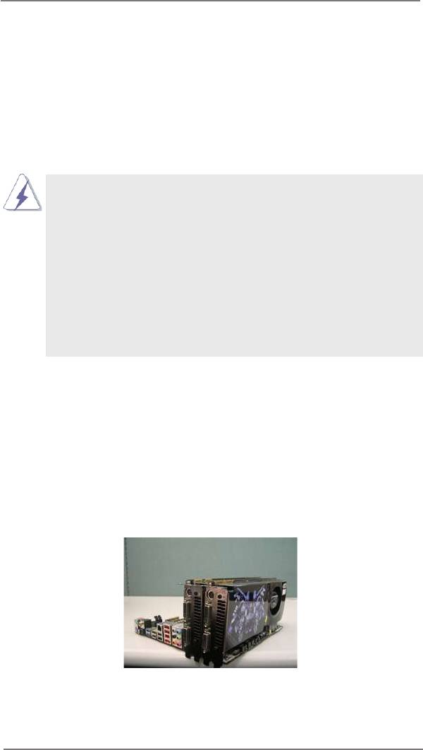
2.5.1.1 Installing Two SLI
-Ready Graphics Cards
TM
®
Step 1. Install the identical SLI
-ready graphics cards that are NVIDIA
certied
because different types of graphics cards will not work together properly.
(Even the GPU chips version shall be the same.) Insert one graphics card
into PCIE1 slot and the other graphics card to PCIE4 slot. Make sure that
the cards are properly seated on the slots.
Step2. If required, connect the auxiliary power source to the PCI Express graph-
ics cards.
23
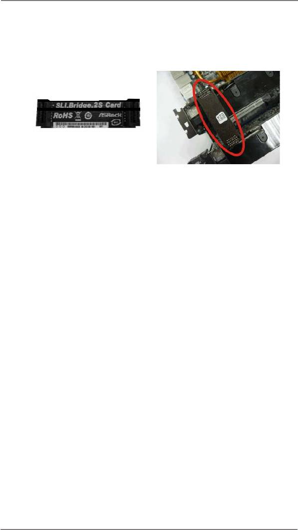
Step3. Align and insert the ASRock SLI_Bridge_2S Card to the goldngers on
each graphics card. Make sure the ASRock SLI_Bridge_2S Card is rmly
in place.
ASRock SLI_Bridge_2S Card
Step4. Connect a VGA cable or a DVI cable to the monitor connector or the DVI
connector of the graphics card that is inserted to PCIE1 slot.
24
TM
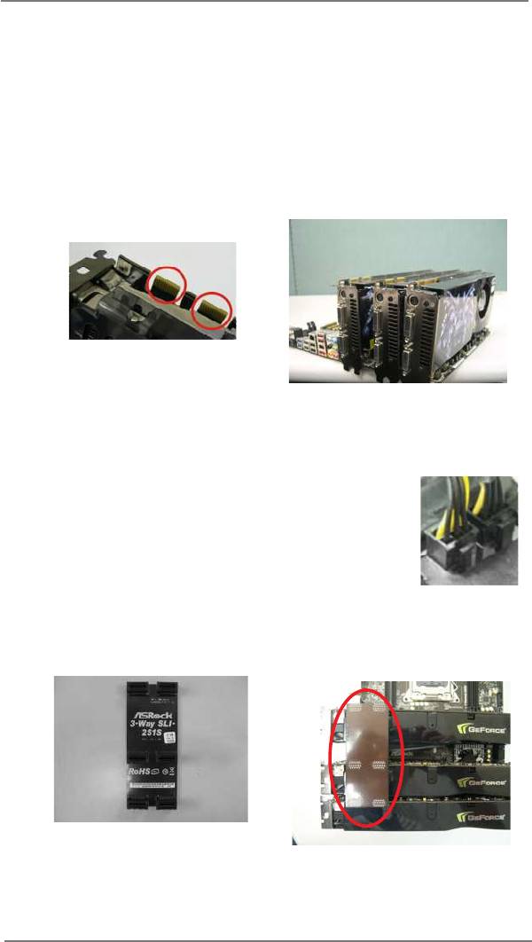
2.5.1.2 Installing Three SLI
-Ready Graphics Cards
TM
®
Step 1. Install the identical 3-Way SLI
-ready graphics cards that are NVIDIA
certied because different types of graphics cards will not work together
properly. (Even the GPU chips version shall be the same.) Each graph-
ics card should have two goldngers for ASRock 3-Way SLI-2S1S Bridge
Card connector. Insert one graphics card into PCIE1 slot, another graphics
card to PCIE4 slot, and the other graphics card to PCIE5 slot. Make sure
that the cards are properly seated on the slots.
Two Goldngers
Step2. Connect the auxiliary power source to the PCI Express graphics card.
Please make sure that both power connectors on the PCI Express graph-
ics card are connected. Repeat this step on the three graphics cards.
Step3. Align and insert ASRock 3-Way SLI-2S1S Bridge Card to the goldngers
on each graphics card. Make sure ASRock 3-Way SLI-2S1S Bridge Card
is rmly in place.
ASRock 3-Way SLI-2S1S Bridge Card
Step4. Connect a VGA cable or a DVI cable to the monitor connector or the DVI
connector of the graphics card that is inserted to PCIE1 slot.
25
2.5.2 Driver Installation and Setup
Install the graphics card drivers to your system. After that, you can enable the Multi-
®
Graphics Processing Unit (GPU) feature in the NVIDIA
nView system tray utility.
Please follow the below procedures to enable the multi-GPU feature.
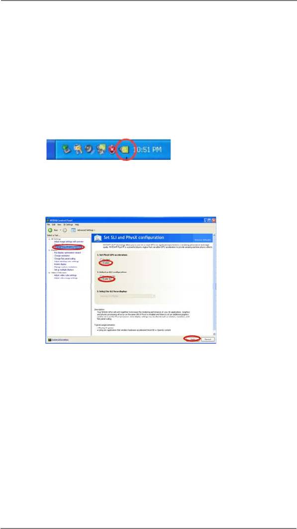
®
For Windows
XP / XP 64-bit OS:
TM
(For SLI
mode only)
®
A. Double-click NVIDIA Settings icon on your Windows
taskbar.
B. From the pop-up menu, select Set SLI and PhysX conguration. In
Set PhysX GPU acceleration item, please select Enabled. In Select
an SLI conguration item, please select Enable SLI. And click Apply.
C. Reboot your system.
TM
D. You can freely enjoy the benet of SLI
feature.
26
®
TM
TM
For Windows
Vista
/ Vista
64-bit / 7 / 7 64-bit / 8 / 8 64-bit OS:
TM
TM
(For SLI
and Quad SLI
mode)
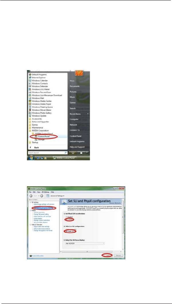
A. Click the Start icon on your Windows taskbar.
B. From the pop-up menu, select All Programs, and then click NVIDIA
Corporation.
C. Select NVIDIA Control Panel tab.
D. Select Control Panel tab.
E. From the pop-up menu, select Set SLI and PhysX conguration. In
Set PhysX GPU acceleration item, please select Enabled. In Select
an SLI conguration item, please select Enable SLI. And click Apply.
F. Reboot your system.
TM
TM
G. You can freely enjoy the benet of SLI
or Quad SLI
feature.
27
®
TM
TM
For Windows
Vista
/ Vista
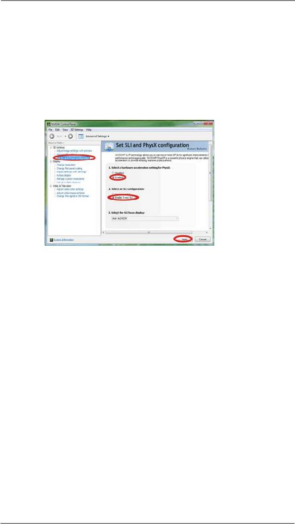
64-bit / 7 / 7 64-bit / 8 / 8 64-bit OS:
TM
(For 3-Way SLI
mode)
A. Follow steps A to D on page 27.
B. From the pop-up menu, select Set SLI and PhysX conguration. In
Select a hardware acceleration setting for PhysX item, please
select Enabled. In Select an SLI conguration item, please select
Enable 3-way SLI. And click Apply.
C. Reboot your system.
TM
D. You can freely enjoy the benet of 3-Way SLI
feature.
TM
®
* SLI
appearing here is a registered trademark of NVIDIA
Technologies Inc., and is used
only for identication or explanation and to the owners’ benet, without intent to infringe.
28
TM
TM
TM
2.6 CrossFireX
, 3-Way CrossFireX
and Quad CrossFireX
Operation Guide
TM
TM
This motherboard supports CrossFireX
, 3-way CrossFireX
and Quad
TM
TM
CrossFireX
feature. CrossFireX
technology offers the most advantageous
means available of combining multiple high performance Graphics Processing
Units (GPU) in a single PC. Combining a range of different operating modes with
TM
intelligent software design and an innovative interconnect mechanism, CrossFireX
enables the highest possible level of performance and image quality in any 3D
TM
®
application. Currently CrossFireX
feature is supported with Windows
XP with
TM
TM
TM
Service Pack 2 / Vista
/ 7 / 8 OS. 3-way CrossFireX
and Quad CrossFireX
®
TM
feature are supported with Windows
Vista
/ 7 / 8 OS only. Please check AMD
TM
website for AMD CrossFireX
driver updates.
1. If a customer incorrectly configures their system they will not see the
TM
TM
performance benets of CrossFireX
. All three CrossFireX
components, a
TM
TM
CrossFireX
Ready graphics card, a CrossFireX
Ready motherboard and a
TM
CrossFireX
Edition co-processor graphics card, must be installed correctly
TM
to benet from the CrossFireX
multi-GPU platform.
TM
2. If you pair a 12-pipe CrossFireX
Edition card with a 16-pipe card, both
TM
cards will operate as 12-pipe cards while in CrossFireX
mode.
2.6.1 Graphics Card Setup
TM
2.6.1.1 Installing Two CrossFireX
-Ready Graphics Cards
TM
Different CrossFireX
cards may require different methods to enable CrossFi-
TM
reX
feature. Please refer to AMD graphics card manuals for detailed installation
guide.
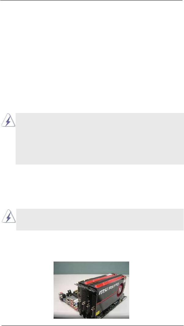
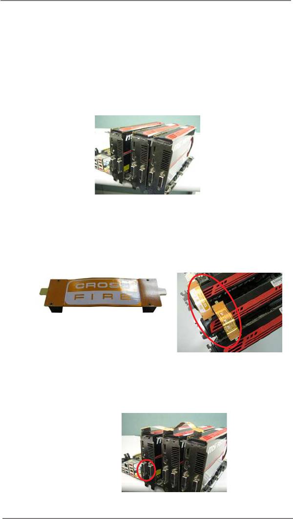
Step 1. Insert one Radeon graphics card into PCIE1 slot and the other Radeon
graphics card to PCIE4 slot. Make sure that the cards are properly seated
on the slots.
29
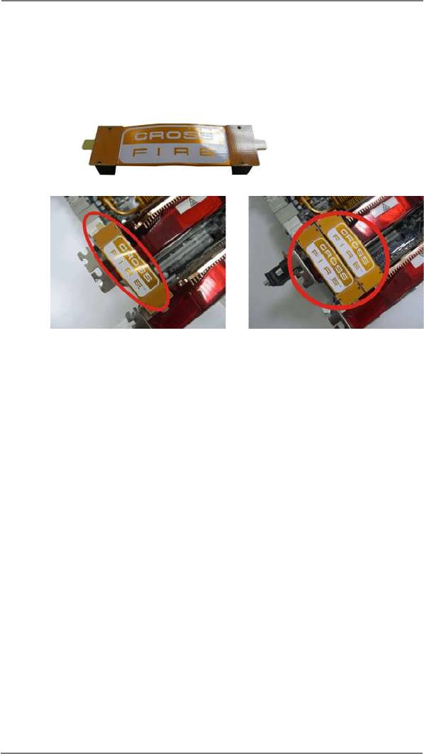
Step 2. Connect two Radeon graphics cards by installing CrossFire Bridge on
CrossFire Bridge Interconnects on the top of Radeon graphics cards.
(CrossFire Bridge is provided with the graphics card you purchase, not
bundled with this motherboard. Please refer to your graphics card vendor
for details.)
CrossFire Bridge
or
Step 3. Connect the DVI monitor cable to the DVI connector on the Radeon graph-
ics card on PCIE1 slot. (You may use the DVI to D-Sub adapter to convert
the DVI connector to D-Sub interface, and then connect the D-Sub monitor
cable to the DVI to D-Sub adapter.)
30
TM
2.6.1.2 Installing Three CrossFireX
-Ready Graphics Cards
TM
Step 1. Install the identical 3-Way CrossFireX
-ready graphics cards that are
AMD certied because different types of graphics cards will not work to-
gether properly. (Even the GPU chips version shall be the same.) Insert
one graphics card into PCIE1 slot, another graphics card to PCIE4 slot,
and the other graphics card to PCIE5 slot. Make sure that the cards are
properly seated on the slots.
TM
Step 2. Use one CrossFire
Bridge to connect Radeon graphics cards on PCIE1
TM
and PCIE4 slots, and use the other CrossFire
Bridge to connect Radeon
TM
graphics cards on PCIE4 and PCIE5 slots. (CrossFire
Bridge is provided
with the graphics card you purchase, not bundled with this motherboard.
Please refer to your graphics card vendor for details.)
TM
CrossFire
Bridge
Step 3. Connect the DVI monitor cable to the DVI connector on the Radeon graph-
ics card on PCIE1 slot. (You may use the DVI to D-Sub adapter to convert
the DVI connector to D-Sub interface, and then connect the D-Sub monitor
cable to the DVI to D-Sub adapter.)
31
2.6.2 Driver Installation and Setup
Step 1. Power on your computer and boot into OS.
TM
Step 2. Remove the ATI
driver if you have any VGA driver installed in your sys-
tem.
The Catalyst Uninstaller is an optional download. We recommend using this
utility to uninstall any previously installed Catalyst drivers prior to installation.
TM
Please check AMD website for ATI
driver updates.
Step 3. Install the required drivers to your system.
®
For Windows
XP OS:
®
A. AMD recommends Windows
XP Service Pack 2 or higher to be
®
installed (If you have Windows
XP Service Pack 2 or higher installed
in your system, there is no need to download it again):
http://www.microsoft.com/windowsxp/sp2/default.mspx
B. You must have Microsoft .NET Framework installed prior to
downloading and installing the CATALYST Control Center. Please
check Microsoft website for details.
®
TM
For Windows
8 / 7 / Vista
OS:
Install the CATALYST Control Center. Please check AMD website for de-
tails.
Step 4. Restart your computer.
Step 5. Install the VGA card drivers to your system, and restart your computer.
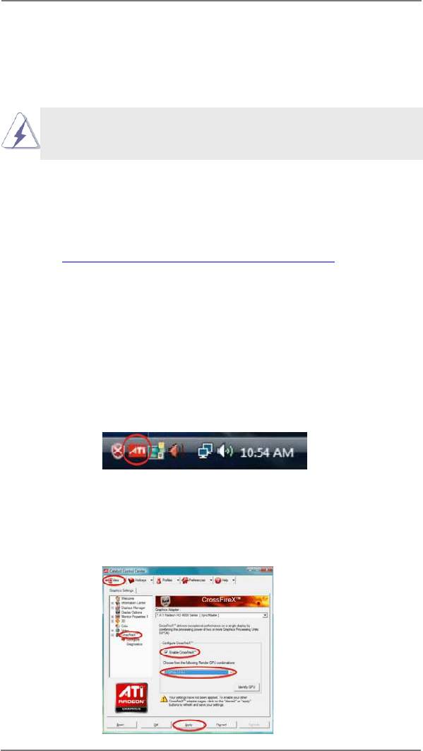
®
Then you will nd “ATI Catalyst Control Center” on your Windows
taskbar.
ATI Catalyst Control Center
Step 6. Double-click “ATI Catalyst Control Center”. Click “View”, select “CrossFi-
TM
TM
reX
”, and then check the item “Enable CrossFireX
”. Select “2 GPUs”
and click “Apply” (if you install two Radeon graphics cards). Select “3
GPUs” and click “OK” (if you install three Radeon graphics cards).
32

TM
Although you have selected the option “Enable CrossFire
”, the Cross-
TM
FireX
function may not work actually. Your computer will automatically
reboot. After restarting your computer, please conrm whether the option
TM
“Enable CrossFire
” in “ATI Catalyst Control Center” is selected or not;
if not, please select it again, and then you are able to enjoy the benet of
TM
CrossFireX
feature.
TM
TM
Step 7. You can freely enjoy the benet of CrossFireX
, 3-Way CrossFireX
or
TM
Quad CrossFireX
feature.
TM
* CrossFireX
appearing here is a registered trademark of AMD Technologies Inc., and is
used only for identication or explanation and to the owners’ benet, without intent to infringe.
TM
* For further information of AMD CrossFireX
technology, please check AMD website for
updates and details.
2.7 Surround Display Feature
This motherboard supports Surround Display upgrade. With the external add-on PCI
Express VGA cards, you can easily enjoy the benets of Surround Display feature.
For the detailed instruction, please refer to the document at the following path in the
Support CD:
..\ Surround Display Information
33
2.8 ASRock Smart Remote Installation Guide
ASRock Smart Remote is only used for ASRock motherboard with CIR header.
Please refer to below procedures for the quick installation and usage of ASRock
Smart Remote.
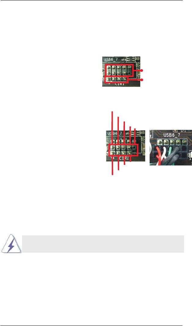
Step1. Find the CIR header located next
to the USB 2.0 header on ASRock
USB 2.0 header (9-pin, black)
motherboard.
CIR header (4-pin, gray)
USB_PWR
Step2. Connect the front USB cable to the
P-
USB 2.0 header (as below, pin 1-5)
P+
and the CIR header. Please make
GND
DUMMY
sure the wire assignments and the
pin assignments are matched
correctly.
1
2
3
4
5
GND
IRTX
IRRX
ATX+5VSB
Step3. Install Multi-Angle CIR Receiver to the front USB port.
Step4. Boot up your system. Press <F2> or <Del> to enter BIOS Setup Utility.
Make sure the option "CIR Controller" is setting at [Enabled].
(Advanced -> Super IO Conguration -> CIR Controller -> [Enabled])
If you cannot nd this option, please shut down your system and install
Multi-Angle CIR Receiver to the other front USB port then try again.
Step5. Enter Windows. Execute ASRock support CD and install CIR Driver. (It is
listed at the bottom of driver list.)
34
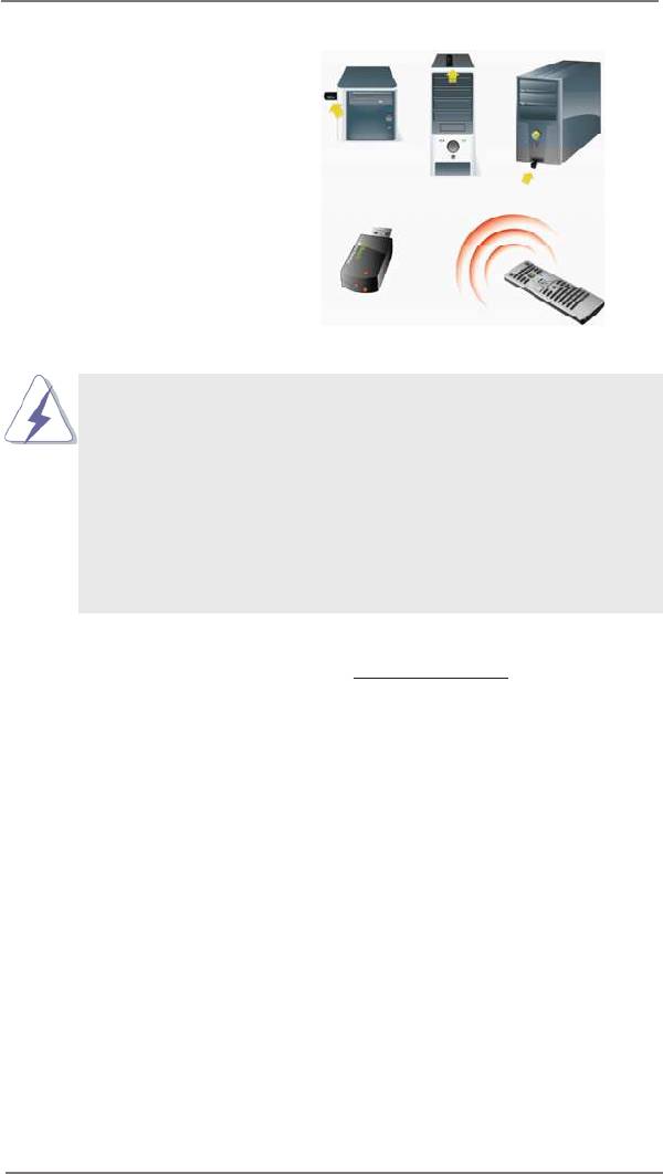
3 CIR sensors in different angles
1. Only one of the front USB port can support CIR function. When
the CIR function is enabled, the other port will remain USB
function.
2. Multi-Angle CIR Receiver is used for front USB only. Please do
not use the rear USB bracket to connect it on the rear panel.
Multi-Angle CIR Receiver can receive the multi-direction infrared
signals (top, down and front), which is compatible with most of
the chassis on the market.
3. The Multi-Angle CIR Receiver does not support Hot-Plug
function. Please install it before you boot the system.
* ASRock Smart Remote is only supported by some of ASRock motherboards. Please refer to
ASRock website for the motherboard support list: http://www.asrock.com
35
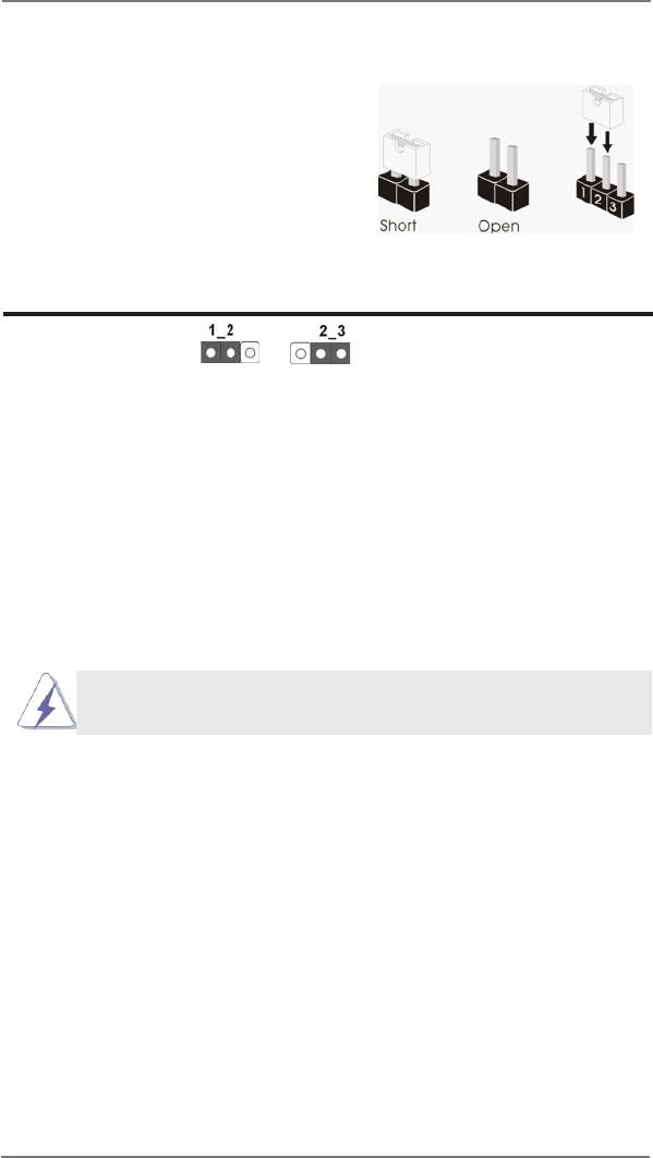
2.9 Jumpers Setup
The illustration shows how jumpers are
setup. When the jumper cap is placed on
pins, the jumper is “Short”. If no jumper cap
is placed on pins, the jumper is “Open”. The
illustration shows a 3-pin jumper whose
pin1 and pin2 are “Short” when jumper cap
is placed on these 2 pins.
Jumper Setting
Clear CMOS Jumper
(CLRCMOS1)
(see p.14, No. 29)
Clear CMOSDefault
Note: CLRCMOS1 allows you to clear the data in CMOS. The data in CMOS in-
cludes system setup information such as system password, date, time, and
system setup parameters. To clear and reset the system parameters to de-
fault setup, please turn off the computer and unplug the power cord from the
power supply. After waiting for 15 seconds, use a jumper cap to short pin2
and pin3 on CLRCMOS1 for 5 seconds. However, please do not clear the
CMOS right after you update the BIOS. If you need to clear the CMOS when
you just nish updating the BIOS, you must boot up the system rst, and then
shut it down before you do the clear-CMOS action.
The Clear CMOS Switch has the same function as the Clear CMOS
jumper.
36
2.10 Onboard Headers and Connectors
Onboard headers and connectors are NOT jumpers. Do NOT place
jumper caps over these headers and connectors. Placing jumper caps
over the headers and connectors will cause permanent damage of the
motherboard!
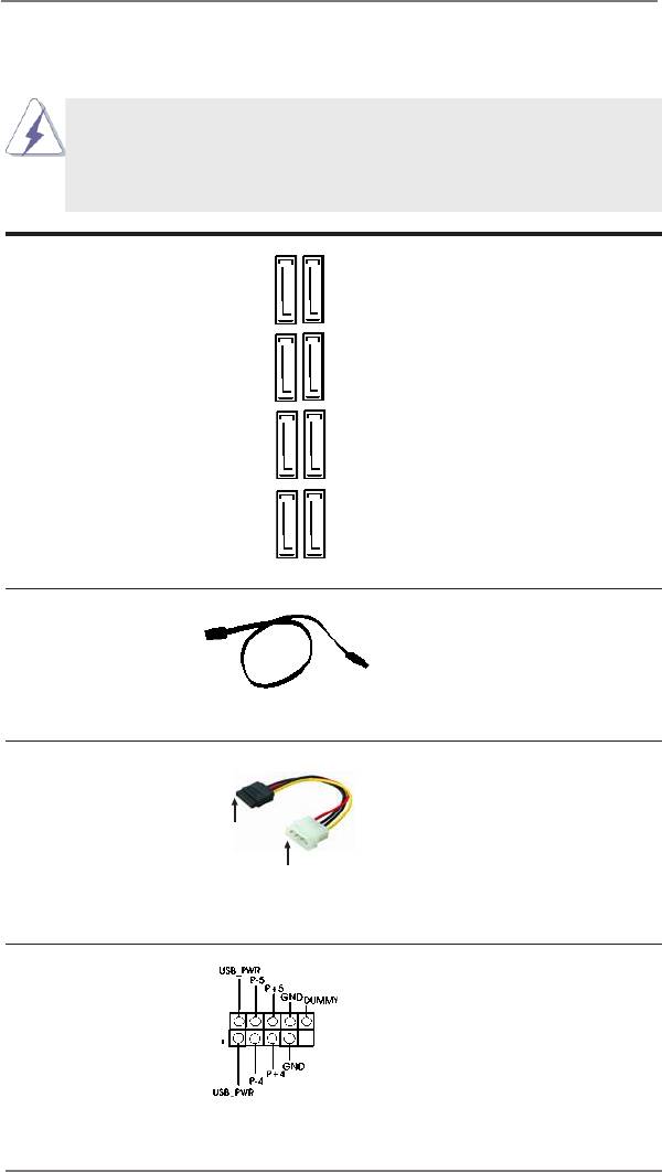
Serial ATA3 Connectors These eight Serial ATA3
(SATA3_1_2: see p.14, No. 18)
(SATA3) connectors support
(SATA3_3_4: see p.14, No. 17)
SATA data cables for internal
(SATA3_5_6: see p.14, No. 16)
storage devices. The current
(SATA3_A1_A2: see p.14, No. 15)
SATA3 interface allows up to
6.0 Gb/s data transfer rate.
SATA3_1 SATA3_3 SATA3_5 SATA3_A1
SATA3_2 SATA3_4 SATA3_6 SATA3_A2
Serial ATA (SATA) Either end of the SATA data
Data Cable cable can be connected to the
(Optional)
SATA3 hard disk or the SATA3
connector on this motherboard.
Serial ATA (SATA) Please connect the black end
Power Cable of SATA power cable to the
(Optional)
power connector on each drive.
connect to the SATA
Then connect the white end of
HDD power connector
SATA power cable to the power
connect to the
power supply
connector of the power supply.
USB 2.0 Headers Besides four default USB 2.0
(9-pin USB4_5)
ports on the I/O panel, there
(see p.14 No. 26)
are two USB 2.0 headers on
this motherboard. Each USB 2.0
header can support two USB
2.0 ports.
37
(9-pin USB6_7)
(see p.14 No. 25)
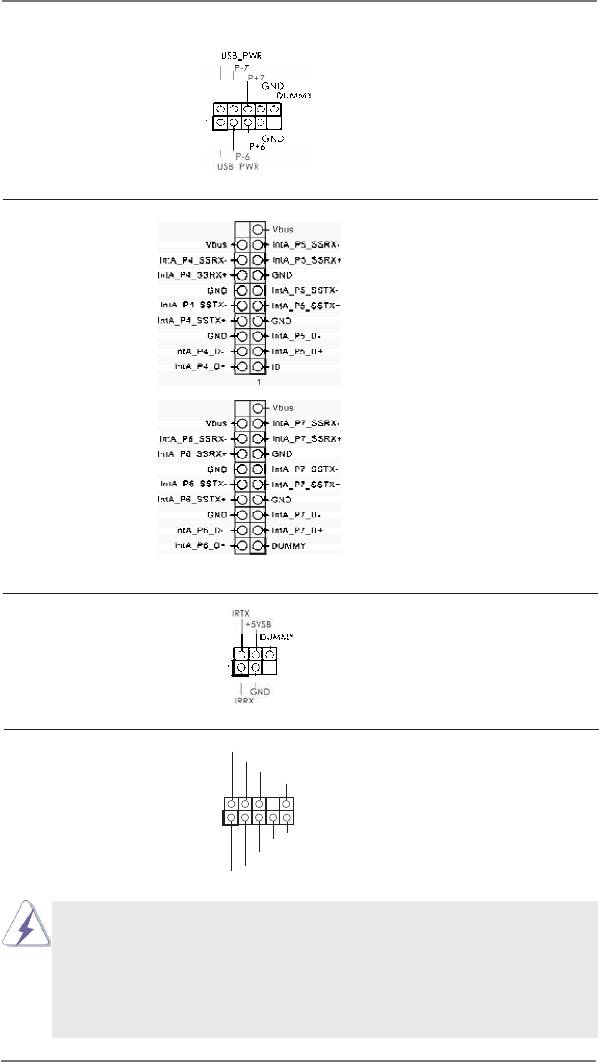
USB 3.0 Headers Besides four default USB 3.0
(19-pin USB3_4_5)
ports on the I/O panel, there are
(see p.14 No. 12)
two USB 3.0 headers on this
motherboard. Each USB 3.0
header can support two USB
3.0 ports.
(19-pin USB3_6_7)
(see p.14 No. 11)
Infrared Module Header This header supports an
(5-pin IR1)
optional wireless transmitting
(see p.14 No. 32)
and receiving infrared module.
Front Panel Audio Header This is an interface for the front
GND
P RESENCE#
(9-pin HD_AUDIO1)
panel audio cable that allows
M IC_RET
OUT_RET
(see p.14 No. 34)
convenient connection and
control of audio devices.
1
O UT2_L
J _SENSE
O UT2_R
M IC2_R
M IC2_L
1. High Denition Audio supports Jack Sensing, but the panel wire on
the chassis must support HDA to function correctly. Please follow the
instruction in our manual and chassis manual to install your system.
2. If you use AC’97 audio panel, please install it to the front panel audio
header as below:
A. Connect Mic_IN (MIC) to MIC2_L.
38
B. Connect Audio_R (RIN) to OUT2_R and Audio_L (LIN) to OUT2_L.
C. Connect Ground (GND) to Ground (GND).
D. MIC_RET and OUT_RET are for HD audio panel only. You don’t
need to connect them for AC’97 audio panel.
E. To activate the front mic.
®
For Windows
XP / XP 64-bit OS:
Select “Mixer”. Select “Recorder”. Then click “FrontMic”.
®
TM
TM
For Windows
8 / 8 64-bit / 7 / 7 64-bit / Vista
/ Vista
64-bit OS:
Go to the “FrontMic” Tab in the Realtek Control panel. Adjust
“Recording Volume”.
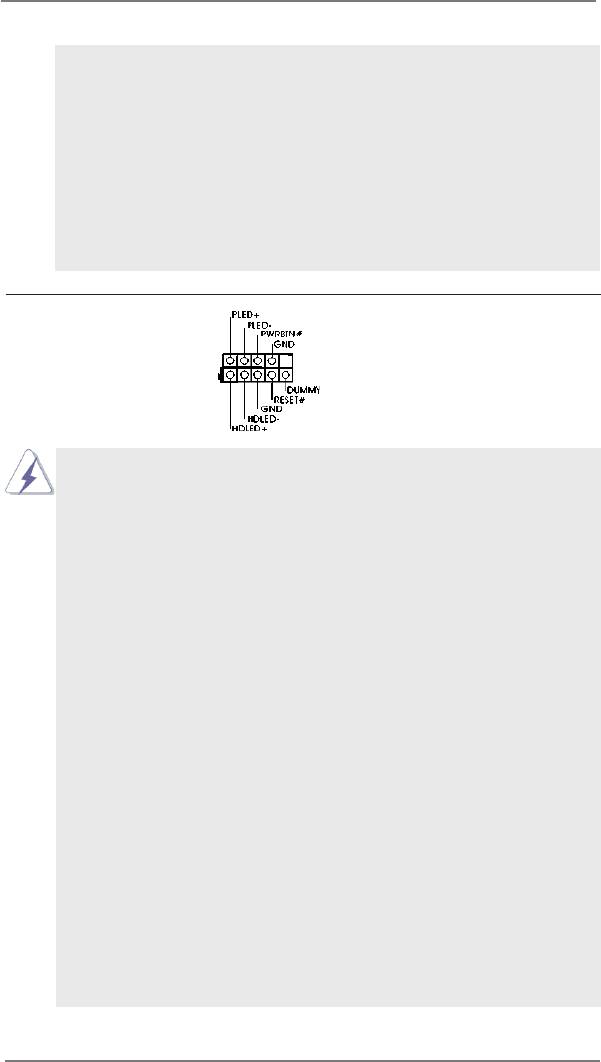
System Panel Header This header accommodates
(9-pin PANEL1)
several system front panel
(see p.14 No. 28)
functions.
Connect the power switch, reset switch and system status indicator
on the chassis to this header according to the pin assignments below.
Note the positive and negative pins before connecting the cables.
PWRBTN (Power Switch):
Connect to the power switch on the chassis front panel. You may con-
gure the way to turn off your system using the power switch.
RESET (Reset Switch):
Connect to the reset switch on the chassis front panel. Press the reset
switch to restart the computer if the computer freezes and fails to per-
form a normal restart.
PLED (System Power LED):
Connect to the power status indicator on the chassis front panel. The
LED is on when the system is operating. The LED keeps blinking
when the sys-tem is in S1 sleep state. The LED is off when the system
is in S3/S4 sleep state or powered off (S5).
HDLED (Hard Drive Activity LED):
Connect to the hard drive activity LED on the chassis front panel. The
LED is on when the hard drive is reading or writing data.
The front panel design may differ by chassis. A front panel module
mainly consists of power switch, reset switch, power LED, hard drive
activity LED, speaker and etc. When connecting your chassis front
panel module to this header, make sure the wire assignments and the
pin assign-ments are matched correctly.
39
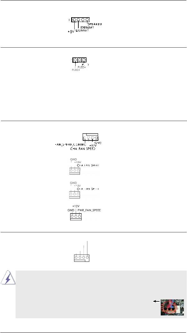
Chassis Speaker Header Please connect the chassis
(4-pin SPEAKER 1)
speaker to this header.
(see p.14 No. 19)
Power LED Header Please connect the chassis
(3-pin PLED1)
power LED to this header to
(see p.14 No. 30)
indicate system power status.
The LED is on when the system
is operating. The LED keeps
blinking in S1 state. The LED is
off in S3/S4 state or S5 state
(power off).
Chassis and Power Fan Connectors Please connect the fan cables
(4-pin CHA_FAN1)
to the fan connectors and
(see p.14 No. 20)
match the black wire to the
ground pin. CHA_FAN1/2/3 fan
speed can be controlled through
(3-pin CHA_FAN2)
UEFI or AXTU.
(see p.14 No. 6)
(3-pin CHA_FAN3)
(see p.14 No. 24)
(3-pin PWR_FAN1)
(see p.14 No. 9)
CPU Fan Connectors Please connect the CPU fan
FAN_SPEED_CONTROL
CPU_FAN_SPEED
(4-pin CPU_FAN1)
cable to the connector and
+ 12V
GND
(see p.14 No. 4)
match the black wire to the
ground pin.
1 2 3 4
Though this motherboard provides 4-Pin CPU fan (Quiet Fan) support, the 3-Pin
CPU fan still can work successfully even without the fan speed control function.
If you plan to connect the 3-Pin CPU fan to the CPU fan connector on this
motherboard, please connect it to Pin 1-3.
Pin 1-3 Connected
3-Pin Fan Installation
40
(3-pin CPU_FAN2)
GND
+ 12V
(see p.14 No. 5)
CPU_FAN_SPEED
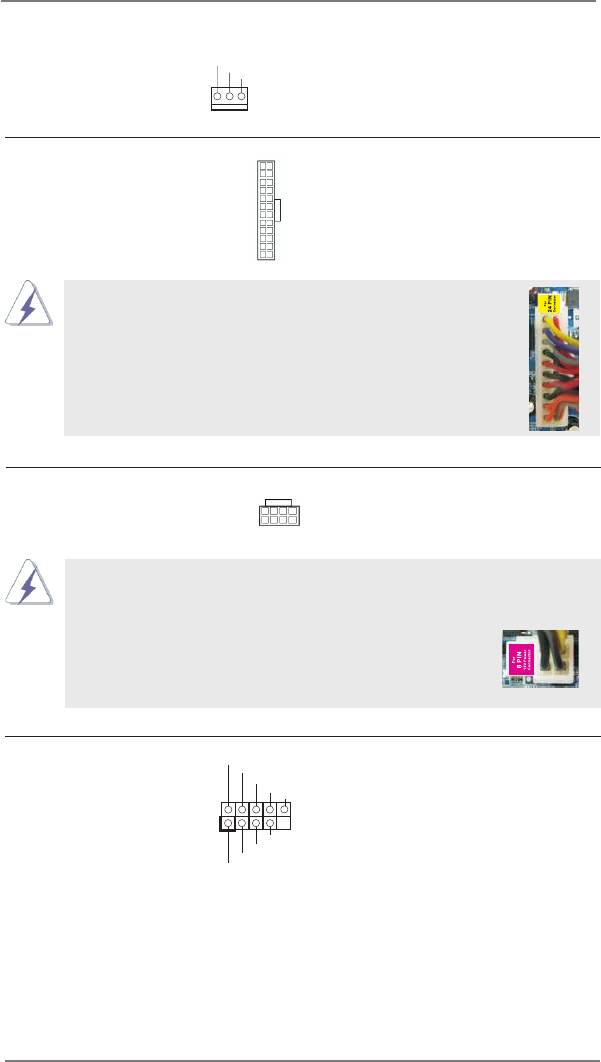
ATX Power Connector Please connect an ATX power
12
24
(24-pin ATXPWR1)
supply to this connector.
(see p.14 No. 10)
1
13
Though this motherboard provides 24-pin ATX power connector,
12
24
it can still work if you adopt a traditional 20-pin ATX power supply.
To use the 20-pin ATX power supply, please plug your
power supply along with Pin 1 and Pin 13.
20-Pin ATX Power Supply Installation
1
13
ATX 12V Power Connector Please connect an ATX 12V
8 5
(8-pin ATX12V1)
power supply to this connector.
(see p.14 No. 1)
4 1
Though this motherboard provides 8-pin ATX 12V power connector, it can still work
if you adopt a traditional 4-pin ATX 12V power supply. To use the 4-pin ATX power
supply, please plug your power supply along with Pin 1 and Pin 5.
8 5
4-Pin ATX 12V Power Supply Installation
4 1
IEEE 1394 Header Besides one default IEEE 1394
RXTPAM_0
GND
(9-pin FRONT_1394)
port on the I/O panel, there is
R XTPBM_0
+ 12V
GND
(see p.14 No. 33)
one IEEE 1394 header
1
(FRONT_1394) on this
+ 12V
R XTPBP_0
motherboard. This IEEE 1394
GND
RXTPAP_0
header can support one IEEE
1394 port.
41
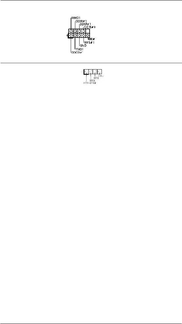
Serial port Header This COM1 header supports a
(9-pin COM1)
serial port module.
(see p.14 No. 31)
Consumer Infrared Module Header This header can be used to
(4-pin CIR1)
connect the remote
(see p.14 No. 27)
controller receiver.
42
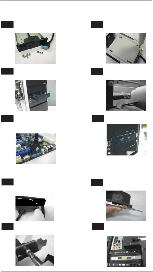
The Installation Guide of Front USB 3.0 Panel
Step 1
Prepare the bundled Front USB 3.0 Panel, four
Step 2
Screw the 2.5” HDD/SSD to the Front
HDD screws, and six chassis screws.
USB 3.0 Panel with four HDD screws.
Step 3
Intall the Front USB 3.0 Panel into the 2.5”
Step 4
Screw the Front USB 3.0 Panel to the
drive bay of the chassis.
drive bay with six chassis screws.
Step 5
Plug the Front USB 3.0 cable into the USB
Step 6
The Front USB 3.0 Panel is ready to use.
3.0 header (USB3_4_5 or USB3_6_7) on the
motherboard.
The Installation Guide of Rear USB 3.0 Bracket
Step 1
Unscrew the two screws from the Front USB 3.0
Step 2
Put the USB 3.0 cable and the rear
Panel.
USB 3.0 bracket together.
Step 3
Screw the two screws into the rear USB 3.0
Step 4
Put the rear USB 3.0 bracket into the
bracket.
chassis.
43
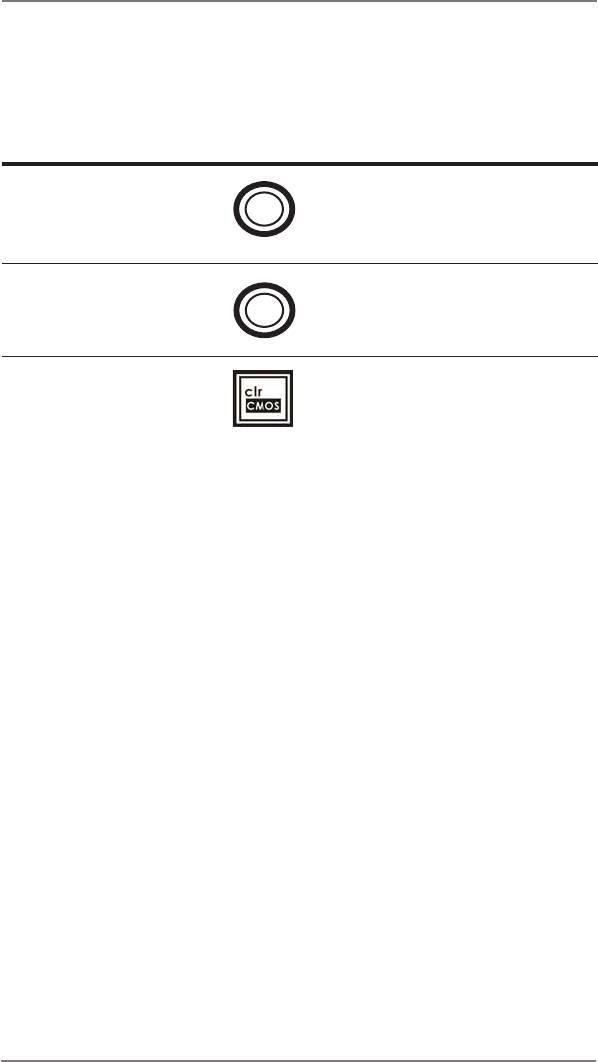
2.11 Smart Switches
The motherboard has three smart switches: power switch, reset switch and clear
CMOS switch, allowing users to quickly turn on/off or reset the sytem clear the
CMOS values.
Power Switch Power Switch is a smart switch,
(PWRBTN)
allowing users to quickly turn
Power
(see p.14 No. 21)
on/off the system.
Reset Switch Reset Switch is a smart switch,
(RSTBTN)
allowing users to quickly reset
Reset
(see p.14 No. 22)
the system.
Clear CMOS Switch Clear CMOS Switch is a smart
(CLRCBTN)
switch, allowing users to quickly
(see p.15 No. 18)
clear the CMOS values.
44

2.12 Dr. Debug
Dr. Debug is used to provide code information, which makes troubleshooting even
easier. Please see the diagrams below for reading the Dr. Debug codes.
Status Code Description
00 Please check if CPU is installed correctly and then clear CMOS.
0d Problem related to memory, VGA card and other devices.
Please clear CMOS, re-install memory and VGA card, and remove other
USB, PCI devices.
01 - 54 Problem related to memory. Please re-install CPU and memory then clear
(except 0d), CMOS.
5A- 60 If the problem still exists, please install only one memory module or try using
other memory modules.
55 Memory could not be detected. Please re-install memory and CPU.
If the problem still exists, please install only one memory module or try using
other memory modules.
61 - 91 Chipset initialization error. Please press reset or clear CMOS.
92 - 99 Problem related to PCI-E devices. Please re-install PCI-E devices or try
installing them in other slots.
If the problem still exists, please remove all PCI-E devices or try using
another VGA card.
A0 - A7 Problem related to IDE or SATA devices. Please re-install IDE and SATA
devices.
If the problem still exists, please clear CMOS and try removing all SATA
devices.
b0 Problem related to memory. Please re-install CPU and memory.
If the problem still exists, please install only one memory module or try using
other memory modules.
b4 Problem related to USB devices. Please try removing all USB devices.
b7 Problem related to memory. Please re-install CPU and memory then clear
CMOS.
If the problem still exists, please install only one memory module or try using
other memory modules.
d6 VGA could not be recognized. Please clear CMOS and try re-installing the
VGA card.
If the problem still exists, please try installing the VGA card in other slots or
using other VGA cards.
d7 Keyboard and mouse could not be recognized. Please try re-installing
keyboard and mouse.
d8 Invalid Password.
FF Please check if CPU is installed correctly and then clear CMOS.
45
2.13 Serial ATA3 (SATA3) Hard Disks Installation
This motherboard adopts AMD SB950 chipset that supports Serial ATA3 (SATA3)
hard disks and RAID (RAID 0, RAID 1, RAID 0+1, JBOD and RAID 5) functions.
It also adopts ASMedia ASM1061 chipset that supports Serial ATA3 (SATA3) hard
disks. You may install SATA3 hard disks on this motherboard for internal storage
devices. This section will guide you to install the SATA3 hard disks.
STEP 1: Install the SATA3 hard disks into the drive bays of your chassis.
STEP 2: Connect the SATA power cable to the SATA3 hard disk.
STEP 3: Connect one end of the SATA data cable to the motherboard’s SATA3
connector.
STEP 4: Connect the other end of the SATA data cable to the SATA3 hard disk.
Please be noted that SATA3_A1 and SATA3_A2 do not support RAID
function. If you want to use RAID function on SATA3 connectors,
please use SATA3_0 to SATA3_6 connectors.
2.14 Hot Plug and Hot Swap Functions for SATA3 HDDs
This motherboard supports Hot Plug and Hot Swap functions for SATA3 in RAID
/ AHCI mode. AMD SB950 and ASMedia ASM1061 chipsets provide hardware
support for Advanced Host controller Interface (AHCI), a new programming interface
for SATA host controllers developed thru a joint industry effort.
NOTE
What is Hot Plug Function?
If the SATA3 HDDs are NOT set for RAID conguration, it is called “Hot
Plug” for the action to insert and remove the SATA3 HDDs while the system
is still power-on and in working condition.
However, please note that it cannot perform Hot Plug if the OS has been
installed into the SATA3 HDD.
What is Hot Swap Function?
If SATA3 HDDs are built as RAID 1 or RAID 5 then it is called “Hot Swap”
for the action to insert and remove the SATA3 HDDs while the system is still
power-on and in working condition.
46
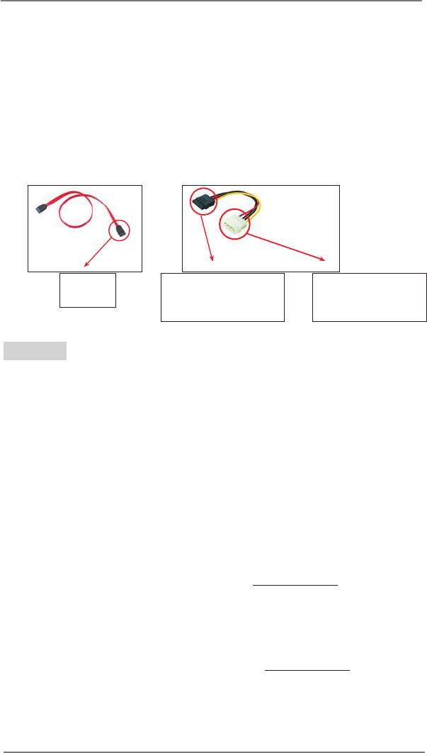
2.15 SATA3 HDD Hot Plug Feature and Operation Guide
This motherboard supports Hot Plug feature for SATA3 HDD in RAID / AHCI
mode. Please read below operation guide of Hot Plug feature carefully. Before you
process the SATA3 HDD Hot Plug, please check below cable accessories from the
motherboard gift box pack.
A. 7-pin SATA data cable
B. SATA power cable with SATA 15-pin power connector interface
A. SATA data cable (Red) B. SATA power cable
SATA 7-pin
The SATA 15-pin power
1x4-pin conventional
connector
connector (Black) connect
power connector (White)
to SATA3 HDD
connect to power supply
Caution
1. Without SATA 15-pin power connector interface, the SATA3 Hot Plug cannot be
processed.
2. Even some SATA3 HDDs provide both SATA 15-pin power connector and IDE
1x4-pin conventional power connector interfaces, the IDE 1x4-pin conventional
power connector interface is denitely not able to support Hot Plug and will cause
the HDD damage and data loss.
Points of attention, before you process the Hot Plug:
1. Below operation procedure is designed only for our motherboard, which supports
SATA3 HDD Hot Plug.
* The SATA3 Hot Plug feature might not be supported by the chipset because of
its limitation, the SATA3 Hot Plug support information of our motherboard is
indicated in the product spec on our website: www.asrock.com
2. Make sure your SATA3 HDD can support Hot Plug function from your dealer or
HDD user manual. The SATA3 HDD, which cannot support Hot Plug function, will
be damaged under the Hot Plug operation.
3. Please make sure the SATA3 driver is installed into system properly. The latest
SATA3 driver is available on our support website: www.asrock.com
4. Make sure to use the SATA power cable & data cable, which are from our
motherboard package.
5. Please follow below instructions step by step to reduce the risk of HDD crash or
data loss.
47
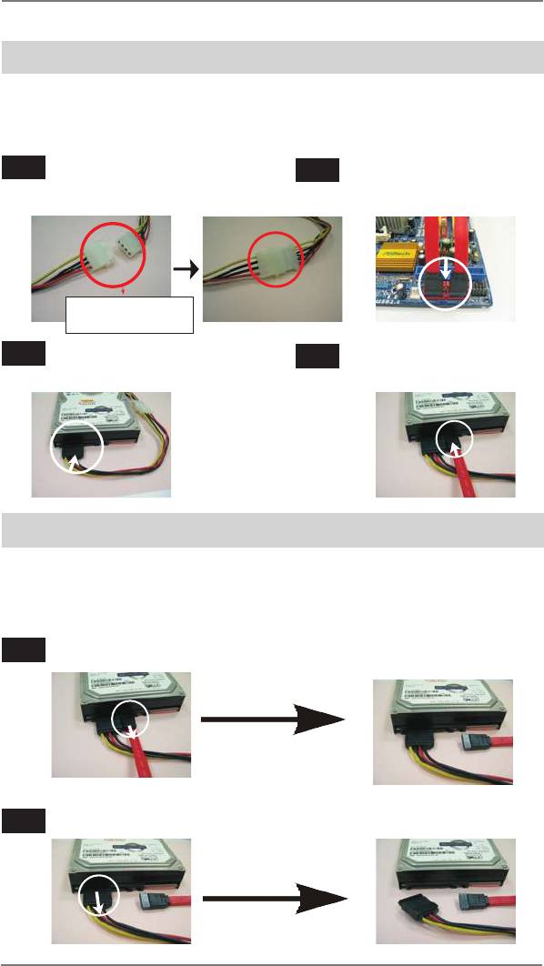
How to Hot Plug a SATA3 HDD:
Points of attention, before you process the Hot Plug:
Please do follow below instruction sequence to process the Hot Plug, improper
procedure will cause the SATA3 HDD damage and data loss.
Step 1
Please connect SATA power cable 1x4-pin
Step 2
Connect SATA data cable to
end (White) to the power supply 1x4-pin
the motherboard’s SATA3
cable.
connector.
SATA power cable 1x4-pin
power connector (White)
Step 3
Connect SATA 15-pin power cable
Step 4
Connect SATA data cable to the
connector (Black) end to SATA3 HDD.
SATA3 HDD.
How to Hot Unplug a SATA3 HDD:
Points of attention, before you process the Hot Unplug:
Please do follow below instruction sequence to process the Hot Unplug, improper
procedure will cause the SATA3 HDD damage and data loss.
Step 1
Unplug SATA data cable from SATA3 HDD side.
Step 2
Unplug SATA 15-pin power cable connector (Black) from SATA3 HDD side.
48

2.16 Driver Installation Guide
To install the drivers to your system, please insert the support CD to your optical
drive rst. Then, the drivers compatible to your system can be auto-detected and
listed on the support CD driver page. Please follow the order from up to bottom side
to install those required drivers. Therefore, the drivers you install can work properly.
®
TM
2.17 Installing Windows
8 / 8 64-bit / 7 / 7 64-bit / Vista
/
TM
Vista
64-bit / XP / XP 64-bit With RAID Functions
®
TM
TM
If you want to install Windows
8 / 8 64-bit / 7 / 7 64-bit / Vista
/ Vista
64-bit / XP /
XP 64-bit on a RAID disk composed of 2 or more SATA3 HDDs with RAID functions,
please follow below procedures according to the OS you install.
®
2.17.1 Installing Windows
XP / XP 64-bit With RAID Functions
®
If you want to install Windows
XP / XP 64-bit on a RAID disk composed of 2 or
more SATA3 HDDs with RAID functions, please follow below steps.
STEP 1: Set up UEFI.
A. Enter UEFI SETUP UTILITY Advanced screen Storage Conguration.
B. Set the “SATA Mode” option to [RAID]. (For SATA3_1 to SATA3_6 ports.)
STEP 2: Make a SATA3 Driver Diskette. (Please use an USB oppy or a oppy
disk.)
A. Insert the ASRock Support CD into your optical drive to boot your system.
B. During POST at the beginning of system boot-up, press <F11> key, and
then a window for boot devices selection appears. Please select CD-ROM as
the boot device.
C. When you see the message on the screen, “Generate Serial ATA driver diskette
[YN]?”, press <Y>.
D. Then you will see these messages,
Please insert a diskette into the oppy drive.
WARNING! Formatting the oppy diskette will
lose ALL data in it!
Start to format and copy les [YN]?
Please insert a oppy diskette into the oppy drive, and press any key.
E. The system will start to format the oppy diskette and copy SATA3 drivers into
the oppy diskette.
49

STEP 3: Use “RAID Installation Guide” to set RAID conguration.
Before you start to congure RAID function, you need to check the RAID installation
guide in the Support CD for proper conguration. Please refer to the BIOS RAID
installation guide part of the document in the following path in the Support CD:
.. \ RAID Installation Guide
®
STEP 4: Install Windows
XP / XP 64-bit OS on your system.
®
After step 1, 2, 3, you can start to install Windows
XP / XP 64-bit OS on your
®
system. At the beginning of Windows
setup, press F6 to install a third-party RAID
driver. When prompted, insert the SATA3 driver diskette containing the AMD RAID
driver. After reading the oppy disk, the driver will be presented. Select the driver to
install according to the OS you install.
®
TM
2.17.2 Installing Windows
8 / 8 64-bit / 7 / 7 64-bit / Vista
/
TM
Vista
64-bit With RAID Functions
®
TM
TM
If you want to install Windows
8 / 8 64-bit / 7 / 7 64-bit / Vista
/ Vista
64-bit on a
RAID disk composed of 2 or more SATA3 HDDs with RAID functions, please follow
below steps.
STEP 1: Set up UEFI.
A. Enter UEFI SETUP UTILITY Advanced screen Storage Conguration.
B. Set the “SATA Mode” option to [RAID]. (For SATA3_1 to SATA3_6 ports.)
STEP 2: Use “RAID Installation Guide” to set RAID conguration.
Before you start to congure RAID function, you need to check the RAID installation
guide in the Support CD for proper conguration. Please refer to the BIOS RAID
installation guide part of the document in the following path in the Support CD:
.. \ RAID Installation Guide
STEP 3: Make a SATA3 Driver Diskette. (Please use an USB oppy or a oppy
disk.)
Make a SATA3 driver diskette by following section 2.17.1 step 2 on page 49.
®
TM
TM
STEP 4: Install Windows
8 / 8 64-bit / 7 / 7 64-bit / Vista
/ Vista
64-bit OS on
your system.
50

®
TM
2.18 Installing Windows
8 / 8 64-bit / 7 / 7 64-bit / Vista
/
TM
Vista
64-bit / XP / XP 64-bit Without RAID Functions
®
TM
TM
If you want to install Windows
8 / 8 64-bit / 7 / 7 64-bit / Vista
/ Vista
64-bit / XP
/ XP 64-bit OS on your SATA3 HDDs without RAID functions, please follow below
procedures according to the OS you install.
®
2.18.1 Installing Windows
XP / XP 64-bit Without RAID
Functions
®
If you want to install Windows
XP / XP 64-bit on your SATA3 HDDs without RAID
functions, please follow below steps.
Using SATA3 HDDs with NCQ and Hot Plug functions (AHCI mode)
STEP 1: Set up UEFI.
A. Enter UEFI SETUP UTILITY Advanced screen Storage Conguration.
B. Set the “SATA Mode” option to [AHCI]. (For SATA3_1 to SATA3_6 ports.)
Set the option “ASMedia SATA3 Mode” to [AHCI]. (For SATA3_A1 and SATA3_A2
ports.)
STEP 2: Make a SATA3 Driver Diskette. (Please use an USB oppy or a oppy
disk.)
Make a SATA3 driver diskette by following section 2.17.1 step 2 on page 49.
®
STEP 3: Install Windows
XP / XP 64-bit OS on your system.
®
You can start to install Windows
XP / XP 64-bit OS on your system. At the begin-
®
ning of Windows
setup, press F6 to install a third-party AHCI driver. When prompt-
ed, insert the SATA3 driver diskette containing the AMD AHCI driver. After reading
the oppy disk, the driver will be presented. Select the driver to install according to
the OS you install.
Using SATA3 HDDs without NCQ and Hot Plug functions (IDE mode)
STEP 1: Set up UEFI.
A. Enter UEFI SETUP UTILITY Advanced screen Storage Conguration.
B. Set the “SATA Mode” option to [IDE]. (For SATA3_1 to SATA3_6 ports.)
Set the option “ASMedia SATA3 Mode” to [IDE]. (For SATA3_A1 and SATA3_A2
ports.)
®
STEP 2: Install Windows
XP / XP 64-bit OS on your system.
51
®
TM
2.18.2 Installing Windows
8 / 8 64-bit / 7 / 7 64-bit / Vista
/
TM
Vista
64-bit Without RAID Functions
®
TM
TM
If you want to install Windows
8 / 8 64-bit / 7 / 7 64-bit / Vista
/ Vista
64-bit on
your SATA3 HDDs without RAID functions, please follow below steps.
Using SATA3 HDDs with NCQ and Hot Plug functions (AHCI mode)
STEP 1: Set up UEFI.
A. Enter UEFI SETUP UTILITY Advanced screen Storage Conguration.
B. Set the “SATA Mode” option to [AHCI]. (For SATA3_1 to SATA3_6 ports.)
Set the option “ASMedia SATA3 Mode” to [AHCI]. (For SATA3_A1 and SATA3_A2
ports.)
®
TM
TM
STEP 2: Install Windows
8 / 8 64-bit / 7 / 7 64-bit / Vista
/ Vista
64-bit OS on
your system.
Using SATA3 HDDs without NCQ and Hot Plug functions (IDE mode)
STEP 1: Set up UEFI.
A. Enter UEFI SETUP UTILITY Advanced screen Storage Conguration.
B. Set the “SATA Mode” option to [IDE]. (For SATA3_1 to SATA3_6 ports.)
Set the option “ASMedia SATA3 Mode” to [IDE]. (For SATA3_A1 and SATA3_A2
ports.)
®
TM
TM
STEP 2: Install Windows
8 / 8 64-bit / 7 / 7 64-bit / Vista
/ Vista
64-bit OS on
your system.
2.19 Untied Overclocking Technology
This motherboard supports Untied Overclocking Technology, which means during
overclocking, FSB enjoys better margin due to xed PCI / PCIE buses. Before you
enable Untied Overclocking function, please enter “Overclock Mode” option of UEFI
setup to set the selection from [Auto] to [Manual]. Therefore, CPU FSB is untied
during overclocking, but PCI / PCIE buses are in the xed mode so that FSB can
operate under a more stable overclocking environment.
Please refer to the warning on page 8 for the possible overclocking risk before you
apply Untied Overclocking Technology.
52


