ASRock 990fx extreme9: 3. UEFI SETUP UTILITY
3. UEFI SETUP UTILITY: ASRock 990fx extreme9

3. UEFI SETUP UTILITY
3.1 Introduction
This section explains how to use the UEFI SETUP UTILITY to congure your
system. The UEFI chip on the motherboard stores the UEFI SETUP UTILITY. You
may run the UEFI SETUP UTILITY when you start up the computer. Please press
<F2> or <Del> during the Power-On-Self-Test (POST) to enter the UEFI SETUP
UTILITY, otherwise, POST will continue with its test routines.
If you wish to enter the UEFI SETUP UTILITY after POST, restart the system by
pressing <Ctl> + <Alt> + <Delete>, or by pressing the reset button on the system
chassis. You may also restart by turning the system off and then back on.
Because the UEFI software is constantly being updated, the
following UEFI setup screens and descriptions are for reference
purpose only, and they may not exactly match what you see on
your screen.
3.1.1 UEFI Menu Bar
The top of the screen has a menu bar with the following selections:
Main For setting system time/date information
OC Tweaker For overclocking congurations
Advanced For advanced system congurations
Tool Useful tools
H/W Monitor Displays current hardware status
Boot For conguring boot settings and boot priority
Security For security settings
Exit Exit the current screen or the UEFI SETUP UTILITY
Use < > key or < > key to choose among the selections on the menu
bar, and use < > key or < > key to move the cursor up or down to
select items, then press <Enter> to get into the sub screen. You can also
navigate with a mouse.
53
3.1.2 Navigation Keys
Please check the following table for the function description of each navigation
key.
Navigation Key(s) Function Description
/ Moves cursor left or right to select Screens
/ Moves cursor up or down to select items
+ / - To change option for the selected items
<Tab> Switch to next function
<Enter> To bring up the selected screen
<PGUP> Go to the previous page
<PGDN> Go to the next page
<HOME> Go to the top of the screen
<END> Go to the bottom of the screen
<F1> To display the General Help Screen
<F7> Discard changes and exit the UEFI SETUP UTILITY
<F9> Load optimal default values for all the settings
<F10> Save changes and exit the UEFI SETUP UTILITY
<F12> Print screen
<ESC> Jump to the Exit Screen or exit the current screen
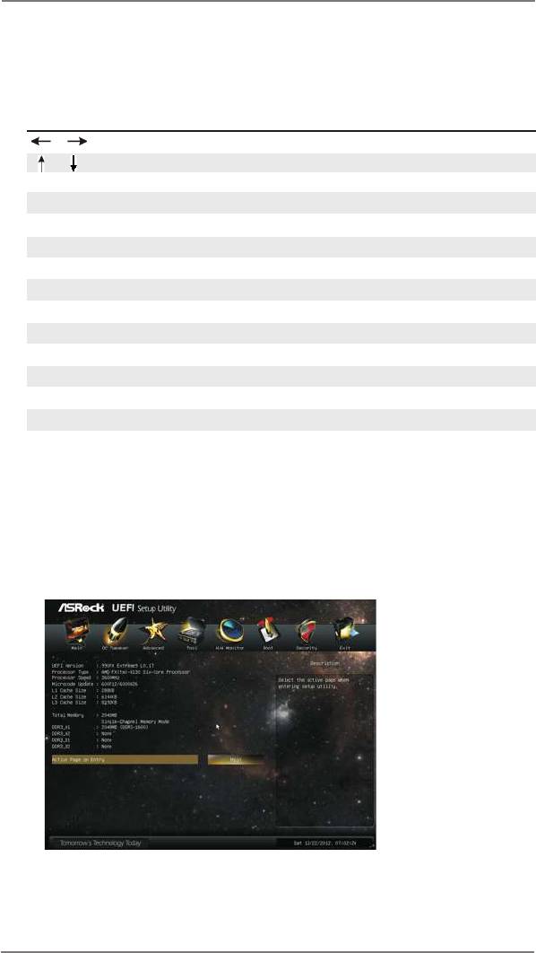
3.2 Main Screen
When you enter the UEFI SETUP UTILITY, the Main screen will appear and display
the system overview.
Active Page on Entry
This allows you to select the default page when entering UEFI setup utility.
54

3.3 OC Tweaker Screen
In the OC Tweaker screen, you can set up overclocking features.
OC Mode
Use this to select Overclock Mode. Please note that overclocing may
cause damage to your components and motherboard. It should be done at
your own risk and expense.
Turbo Mode
This item appears only when you set the item “OC Mode“ to [Turbo Mode].
You can use this option to increase your system performance. Congura-
tion options: [System Performance Increases 50%] and [System Perfor-
mance Increases 60%].
CPU Conguration
Overclock Mode
Use this to select Overclock Mode. Configuration options: [Auto] and
[Manual]. The default value is [Auto].
Spread Spectrum
This item should always be [Auto] for better system stability.
ASRock UCC
ASRock UCC (Unlock CPU Core) feature simplies AMD CPU activation.
As long as a simple switch of the UEFI option “ASRock UCC”, you can
unlock the extra CPU core to enjoy an instant performance boost. When
UCC feature is enabled, the dual-core or triple-core CPU will boost to the
quad-core CPU, and some CPU, including quad-core CPU, can also in-
crease L3 cache size up to 6MB, which means you can enjoy the upgrade
CPU performance with a better price. Please be noted that UCC feature is
supported with AM3/AM3+ CPU only, and in addition, not every AM3/AM3+
CPU can support this function because some CPU’s hidden core may be
malfunctioned.
55

CPU Active Core Control
This allows you to adjust CPU Active Core Control feature. The congura-
tion options depend on the CPU core you adopt. The default value is [Dis-
abled].
AMD Turbo Core Technology
This item appears only when the processor you adopt supports this fea-
ture. Use this to select enable or disable AMD Turbo Core Technology.
Conguration options: [Enabled] and [Disabled]. The default value is
[Enabled].
AMD Application Power Management
Application Power Management (APM) ensures that average power con-
sumption over a thermally significant time period remains at or below
the TDP for the CPU mode being used. If [Enabled] is selected, the power
consumption is reduced when overclocking.
Processor Maximum Frequency
It will display Processor Maximum Frequency for reference.
North Bridge Maximum Frequency
It will display North Bridge Maximum Frequency for reference.
Processor Maximum Voltage
It will display Processor Maximum Voltage for reference.
Multiplier/Voltage Change
This item is set to [Auto] by default. If it is set to [Manual], you may adjust
the value of Processor Frequency and Processor Voltage. However, it is
recommended to keep the default value for system stability.
CPU Frequency Multiplier
For safety and system stability, it is not recommended to adjust the value
of this item.
CPU Voltage
It allows you to adjust the value of CPU voltage. However, for safety and
system stability, it is not recommended to adjust the value of this item.
NB Frequency Multiplier
For safety and system stability, it is not recommended to adjust the value
of this item.
CPU NB Voltage
It allows you to adjust the value of CPU NB voltage. However, for safety
and system stability, it is not recommended to adjust the value of this item.
56
HT Bus Speed
This feature allows you selecting Hyper-Transport bus speed. Congura-
tion options: [200MHz] to [2000MHz].
HT Bus Width
This feature allows you selecting Hyper-Transport bus width. Conguration
options: [8 Bit] and [16 Bit].
DRAM Timing Conguration
DRAM Frequency
If [Auto] is selected, the motherboard will detect the memory module(s)
inserted and assigns appropriate frequency automatically.
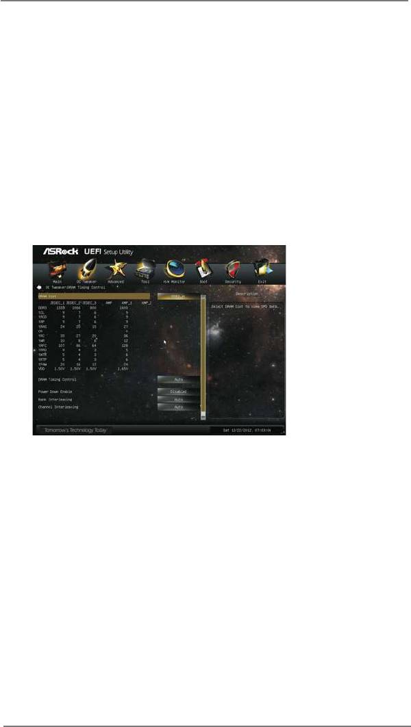
DRAM Timing Control
DRAM Slot
Use this item to view SPD data.
DRAM Timing Control
Use this item to control DRAM timing.
Power Down Enable
Use this item to enable or disable DDR power down mode.
Bank Interleaving
Interleaving allows memory accesses to be spread out over banks on the
same node, or accross nodes, decreasing access contention.
Channel Interleaving
It allows you to enable Channel Memory Interleaving. Conguration op-
tions: [Disabled], [Auto]. The default value is [Auto].
57

Voltage Conguration
CPU Load-line calibration
Use this to select CPU Load-line calibration. The default value is [Auto].
DRAM Voltage
Use this to select DRAM Voltage. The default value is [Auto].
NB Voltage
Use this to select NB Voltage. The default value is [Auto].
HT Voltage
Use this to select HT Voltage. The default value is [Auto].
CPU VDDA Voltage
Use this to select CPU VDDA Voltage. The default value is [Auto].
PCIE VDDA Voltage
Use this to select PCIE VDDA Voltage. The default value is [Auto].
58
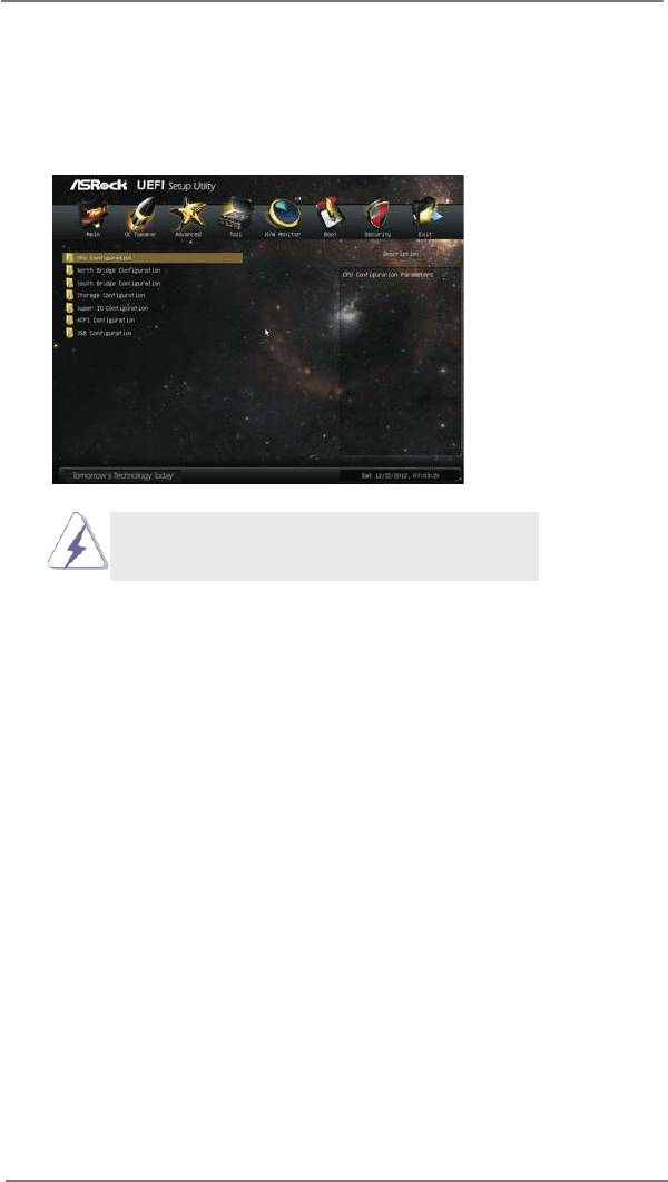
3.4 Advanced Screen
In this section, you may set the congurations for the following items: CPU Congu-
ration, Nouth Bridge Conguration, South Bridge Conguration, Storage Congura-
tion, Super IO Conguration, ACPI Conguration and USB Conguration.
Setting wrong values in this section may cause
the system to malfunction.
59

3.4.1 CPU Conguration
Cool ‘n’ Quiet
TM
Use this item to enable or disable AMD’s Cool ‘n’ Quiet
technology. The
default value is [Enabled]. Conguration options: [Enabled] and [Disabled].
®
TM
If you install Windows
8 / 7 / Vista
and want to enable this function,
please set this item to [Enabled]. Please note that enabling this function
may reduce CPU voltage and memory frequency, and lead to system sta-
bility or compatibility issue with some memory modules or power supplies.
Please set this item to [Disable] if above issue occurs.
Enhance Halt State (C1E)
All processors support the Halt State (C1). The C1 state is supported
through the native processor instructions HLT and MWAIT and requires no
hardware support from the chipset. In the C1 power state, the processor
maintains the context of the system caches.
Secure Virtual Machine
When this option is set to [Enabled], a VMM (Virtual Machine Architecture)
can utilize the additional hardware capabilities provided by AMD-V. The
default value is [Enabled]. Conguration options: [Enabled] and [Disabled].
Core C6 Mode
Use this item to enable or disable Core C6 mode. The default value is
[Enabled].
CPU Thermal Throttle
Use this item to enable CPU internal thermal control mechanism to keep
the CPU from overheated. The default value is [Auto].
60

3.4.2 North Bridge Conguration
Primary Graphics Adapter
This item will switch the PCI Bus scanning order while searching for video
card. It allows you to select the type of Primary VGA in case of multiple
video controllers. The default value of this feature is [PCI Express]. Con-
guration options: [PCI] and [PCI Express].
IOMMU
Use this to enable or disable IOMMU. The default value of this feature is
[Disabled].
61

3.4.3 South Bridge Conguration
Onboard HD Audio
Select [Auto], [Enabled] or [Disabled] for the onboard HD Audio feature. If
you select [Auto], the onboard HD Audio will be disabled when PCI Sound
Card is plugged.
Front Panel
Select [Auto] or [Disabled] for the onboard HD Audio Front Panel.
Onboard LAN
This allows you to enable or disable the onboard LAN feature.
Onboard IEEE 1394
This allows you to enable or disable the onboard IEEE 1394.
Onboard Debug Port LED
This allows you to enable or disable the onboard Debug Port LED.
Good Night LED
This allows you to enable to turn off Power LED, Lan LED at power on.
62

3.4.4 Storage Conguration
SATA Controller
This item is for SATA3_1 to SATA3_6 ports. Use this item to enable or dis-
able the “SATA Controller” feature.
SATA Mode
This item is for SATA3_1 to SATA3_6 ports.Use this item to adjust SATA
Mode. The default value of this option is [AHCI Mode]. Conguration op-
tions: [AHCI Mode], [RAID Mode] and [IDE Mode].
If you set this item to RAID mode, it is suggested to install SATA
ODD driver on SATA3_5 or SATA3_6 port.
AMD AHCI BIOS ROM
Use this item to enable or disable AMD AHCI BIOS ROM. The default
value of this option is [Disabled].
SATA IDE Combined Mode
This item is for SATA3_5 and SATA3_6 ports. Use this item to enable or
disable SATA IDE combined mode. The default value is [Enabled].
If you want to build RAID on SATA3_5 and SATA3_6 ports,
please disable this item.
Aggressive Link Power Management
Use this item to congure Aggressive Link Power Management.
Hard Disk S.M.A.R.T.
Use this item to enable or disable the S.M.A.R.T. (Self-Monitoring, Analy-
sis, and Reporting Technology) feature. Conguration options: [Disabled],
[Auto] and [Enabled].
63

ASMedia SATA3 Mode
This item is for SATA3_A1 and SATA3_A2 ports. Use this item to adjust
the “ASMedia SATA3 Mode” feature. Conguration options: [Disabled], [IDE
Mode] and [AHCI Mode]. The default value is [AHCI Mode].
SATA Boot ROM
Use this to enable or disable Onboard ASMedia SATA3 Option ROM. If
Option ROM is disabled, UEFI cannot use the SATA device to connect to
ASMedia SATA3 controller as Boot Device.
We recommend to use SATA3_1 to SATA3_6 ports for your
bootable device. This will minimum your boot time and get the
best performance. But if you still want to boot from ASMedia
SATA3 controller, please set this item to [Yes].
64

3.4.5 Super IO Conguration
Serial Port
Use this item to enable or disable the onboard serial port.
Serial Port Address
Use this item to set the address for the onboard serial port. Conguration
options: [3F8h / IRQ4] and [3E8h / IRQ4].
Infrared Port
Use this item to enable or disable the onboard infrared port.
Infrared Port Address
Use this item to set the address for the onboard infrared port.Conguration
options: [2F8h / IRQ3] and [2E8h / IRQ3].
65

3.4.6 ACPI Conguration
Suspend to RAM
Use this item to select whether to auto-detect or disable the Suspend-to-
RAM feature. Select [Auto] will enable this feature if the OS supports it.
Check Ready Bit
Use this item to enable or disable the feature Check Ready Bit.
ACPI HPET table
Use this item to enable or disable ACPI HPET Table. The default value is
[Enabled]. Please set this option to [Enabled] if you plan to use this moth-
®
erboard to submit Windows
certication.
Restore on AC/Power Loss
This allows you to set the power state after an unexpected AC/power loss.
If [Power Off] is selected, the AC/power remains off when the power re-
covers. If [Power On] is selected, the AC/power resumes and the system
starts to boot up when the power recovers.
PS/2 Keyboard Power On
Use this item to enable or disable PS/2 keyboard to turn on the system
from the power-soft-off mode.
PCI Devices Power On
Use this item to enable or disable PCI devices to turn on the system from
the power-soft-off mode.
Ring-In Power On
Use this item to enable or disable Ring-In signals to turn on the system
from the power-soft-off mode.
RTC Alarm Power On
Use this item to enable or disable RTC (Real Time Clock) to power on the
system.
66

USB Phy Power Down
Use this item to enable the USB PHY to power down in S4/S5 state.
USB Keyboard/Remote Power On
Use this item to enable or disable the system to wake from S5 using USB
Keyboard/Remote.
USB Mouse Power On
Use this item to enable or disable the system to wake from S5 using USB
Mouse.
CSM
Please disable CSM when you enable Fast Boot option. The default value
is [Enabled].
67

3.4.7 USB Conguration
USB 2.0 Controller
Use this item to enable or disable the use of USB 2.0 controller.
USB 3.0 Controller
Use this item to enable or disable the use of USB 3.0 controller.
Legacy USB Support
Use this option to select legacy support for USB devices. There are four
con guration options: [Enabled], [Disabled], [Auto] and [UEFI Setup Only].
The default value is [Enabled]. Please refer to below descriptions for the
details of these four options:
[Enabled] - Enables support for legacy USB.
[Disabled] - USB devices are not allowed to use under legacy OS and
UEFI setup when [Disabled] is selected. If you have USB compatibility is-
sue, it is recommended to select [Disabled] to enter OS.
[Auto] - Enables legacy support if USB devices are connected.
[UEFI Setup Only] - USB devices are allowed to use only under UEFI
setup and Windows / Linux OS.
Legacy USB 3.0 Support
Use this option to enable or disable legacy support for USB 3.0 devices.
The default value is [Disabled].
68

3.5 Tool
System Browser
System Browser can let you easily check your current system congura-
tion in UEFI setup.
OMG (Online Management Guard)
Administrators are able to establish an internet curfew or restrict internet
access at specied times via OMG. You may schedule the starting and
ending hours of internet access granted to other users. In order to prevent
users from bypassing OMG, guest accounts without permission to modify
the system time are required.
Easy RAID Installer
Easy RAID Installer can help you to copy the RAID driver from a support
CD to your USB storage device. After copying the RAID driver to your
USB storage device, please change “SATA Mode” to “RAID”, then you
can start installing the OS in RAID mode.
UEFI Update Utility
Instant Flash
Instant Flash is a UEFI ash utility embedded in Flash ROM. This conve-
nient UEFI update tool allows you to update system UEFI without enter-
®
ing operating systems rst like MS-DOS or Windows
. Just save the new
UEFI le to your USB ash drive, oppy disk or hard drive and launch this
tool, then you can update your UEFI only in a few clicks without prepar-
ing an additional oppy diskette or other complicated ash utility. Please
be noted that the USB ash drive or hard drive must use FAT32/16/12 le
system. If you execute Instant Flash utility, the utility will show the UEFI
les and their respective information. Select the proper UEFI le to up-
date your UEFI, and reboot your system after the UEFI update process is
completed.
69

Internet Flash
Internet Flash searches for available UEFI firmware updates from our
servers. In other words, the system can auto-detect the latest UEFI from
our servers and ash them without entering Windows OS.
Network Conguration
Internet Setting
Use this item to set up the internet connection mode. Conguration
options: [DHCP (Auto IP)] and [PPPOE].
UEFI Download Server
Use this item to select UEFI rmware download server for Internet Flash.
Conguration options: [Asia], [Europe], [USA] and [China].
Dehumidier Function
Users may prevent motherboard damages due to dampness by enabling
“Dehumidier Function”. When enabling Dehumidier Function, the com-
puter will power on automatically to dehumidify the system after entering
S4/S5 state.
Dehumidier Period
This allows users to congure the period of time until the computer powers
on and enables “Dehumidier” after entering S4/S5 state.
Dehumidier Duration
This allows users to congure the duration of the dehumidifying process
before it returns to S4/S5 state.
Dehumidier CPU Fan Setting
Use this setting to congure CPU fan speed while “Dehumidier” is en-
abled.
70

Would you like to save current setting user defaults?
In this option, you are allowed to load and save three user defaults
according to your own requirements.
71

3.6 Hardware Health Event Monitoring Screen
In this section, it allows you to monitor the status of the hardware on your system,
including the parameters of the CPU temperature, motherboard temperature, CPU
fan speed, chassis fan speed, and the critical voltage.
CPU Fan 1 & 2 Setting
This allows you to set the CPU fan 1 & 2 speed. Con guration options: [Full
On] and [Automatic Mode]. The default is value [Full On].
Chassis Fan 1 Setting
This allows you to set the chassis fan 1 speed. Con guration options: [Full
On] and [Automatic Mode]. The default is value [Full On].
Chassis Fan 2 Setting
This allows you to set the chassis fan 2 speed. Con guration options: [Full
On] and [Manual]. The default is value [Full On].
Chassis Fan 3 Setting
This allows you to set the chassis fan 3 speed. Con guration options: [Full
On] and [Manual]. The default is value [Full On].
72

3.7 Boot Screen
In this section, it will display the available devices on your system for you to cong-
ure the boot settings and the boot priority.
Fast Boot
Fast Boot minimizes your computer’s boot time. There are three con-
guration options: [Disabled], [Fast] and [Ultra Fast]. The default value is
[Disabled]. Please refer to below descriptions for the details of these three
options:
[Disabled] - Disable Fast Boot.
[Fast] - The only restriction is you may not boot by using an USB ash
drive.
[Ultra Fast] - There are a few restrictions.
®
1. Only supports Windows
8 UEFI operating system.
2. You will not be able to enter BIOS Setup (Clear CMOS or run utility
®
in Widows
to enter BIOS Setup).
3. If you are using an external graphics card, the VBIOS must support
UEFI GOP in order to boot.
Boot From Onboard LAN
Use this item to enable or disable the Boot From Onboard LAN feature.
Setup Prompt Timeout
This shows the number of seconds to wait for setup activation key.
Bootup Num-Lock
If this item is set to [On], it will automatically activate the Numeric Lock
function after boot-up.
73

Full Screen Logo
Use this item to enable or disable OEM Logo. The default value is [En-
abled].
AddOn ROM Display
Use this option to adjust AddOn ROM Display. If you enable the option “Full
Screen Logo” but you want to see the AddOn ROM information when the
system boots, please select [Enabled]. Conguration options: [Enabled]
and [Disabled]. The default value is [Enabled].
Boot Failure Guard
Enable or disable the feature of Boot Failure Guard.
Boot Failure Guard Count
Enable or disable the feature of Boot Failure Guard Count.
74

3.8 Security Screen
In this section, you may set or change the supervisor/user password for the system.
For the user password, you may also clear it.
Secure Boot
Use this to enable or disable Secure Boot. The default value is [Disabled].
75

3.9 Exit Screen
Save Changes and Exit
When you select this option, it will pop-out the following message, “Save
conguration changes and exit setup?” Select [OK] to save the changes
and exit the UEFI SETUP UTILITY.
Discard Changes and Exit
When you select this option, it will pop-out the following message, “Discard
changes and exit setup?” Select [OK] to exit the UEFI SETUP UTILITY
without saving any changes.
Discard Changes
When you select this option, it will pop-out the following message, “Discard
changes?” Select [OK] to discard all changes.
Load UEFI Defaults
Load UEFI default values for all the setup questions. F9 key can be used
for this operation.
76


