ASRock 970 extreme3 r2.0 – страница 2
Инструкция к Материнской Плате ASRock 970 extreme3 r2.0
2.5.2 Driver Installation and Setup
Step 1. Power on your computer and boot into OS.
Step 2. Remove the AMD driver if you have any VGA driver installed in your sys-
tem.
The Catalyst Uninstaller is an optional download. We recommend using this
utility to uninstall any previously installed Catalyst drivers prior to installation.
Please check AMD website for AMD driver updates.
Step 3. Install the required drivers to your system.
®
For Windows
XP OS:
®
A. AMD recommends Windows
XP Service Pack 2 or higher to be
®
installed (If you have Windows
XP Service Pack 2 or higher installed
in your system, there is no need to download it again):
http://www.microsoft.com/windowsxp/sp2/default.mspx
B. You must have Microsoft .NET Framework installed prior to
downloading and installing the CATALYST Control Center. Please
check Microsoft website for details.
®
TM
For Windows
8 / 7 / Vista
OS:
Install the CATALYST Control Center. Please check AMD website for de-
tails.
Step 4. Restart your computer.
Step 5. Install the VGA card drivers to your system, and restart your computer.
®
Then you will nd “ATI Catalyst Control Center” on your Windows
taskbar.
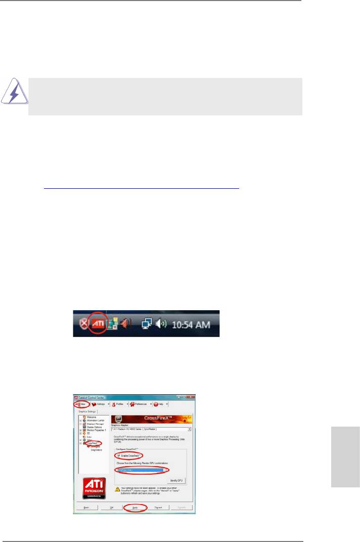
ATI Catalyst Control Center
Step 6. Double-click “ATI Catalyst Control Center”. Click “View”, select “CrossFi-
TM
TM
reX
”, and then check the item “Enable CrossFireX
”. Select “2 GPUs”
and click “Apply” (if you install two Radeon graphics cards).
English
21
ASRock 970 Extreme3 R2.0 Motherboard
TM
Although you have selected the option “Enable CrossFire
”, the Cross-
TM
FireX
function may not work actually. Your computer will automatically
reboot. After restarting your computer, please conrm whether the option
TM
“Enable CrossFire
” in “ATI Catalyst Control Center” is selected or not;
if not, please select it again, and then you are able to enjoy the benet of
TM
CrossFireX
feature.
TM
TM
Step 7. You can freely enjoy the benet of CrossFireX
or Quad CrossFireX
feature.
TM
* CrossFireX
appearing here is a registered trademark of AMD Technologies Inc., and is
used only for identication or explanation and to the owners’ benet, without intent to infringe.
TM
* For further information of AMD CrossFireX
technology, please check AMD website for
updates and details.
English
22
ASRock 970 Extreme3 R2.0 Motherboard
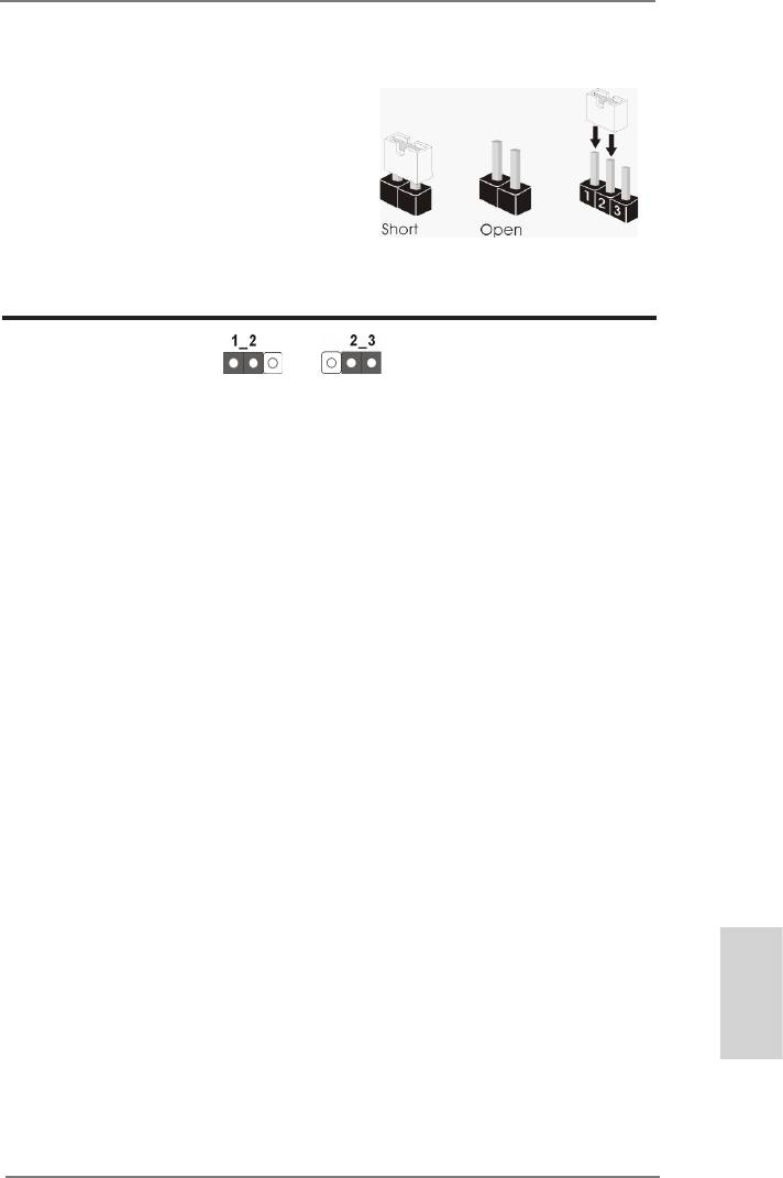
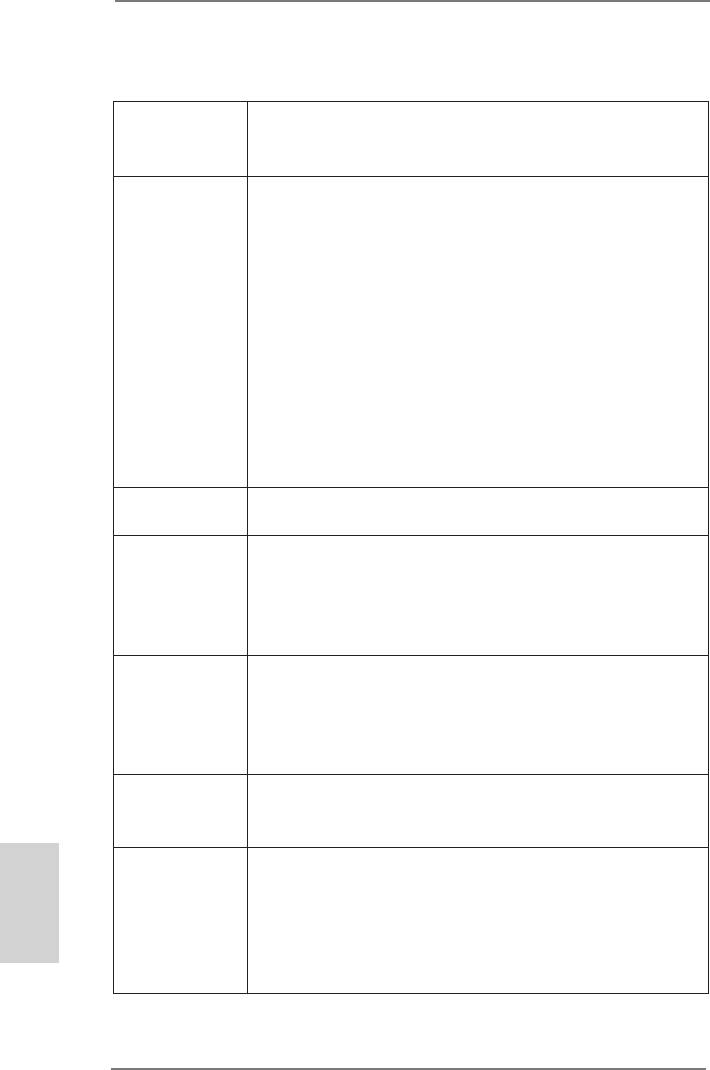
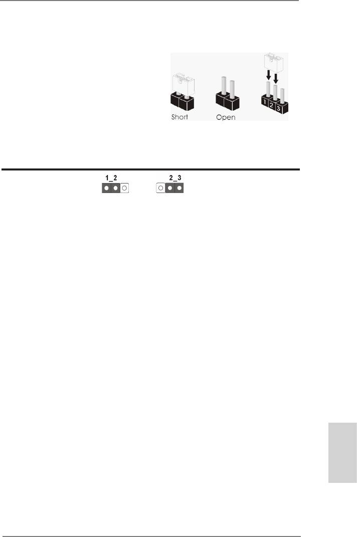
2.6 Jumpers Setup
The illustration shows how jumpers are
setup. When the jumper cap is placed on
pins, the jumper is “Short”. If no jumper cap
is placed on pins, the jumper is “Open”. The
illustration shows a 3-pin jumper whose
pin1 and pin2 are “Short” when jumper cap
is placed on these 2 pins.
Jumper Setting Description
Clear CMOS Jumper
(CLRCMOS1)
(see p.2, No. 21)
Clear CMOSDefault
Note: CLRCMOS1 allows you to clear the data in CMOS. To clear and reset the
system parameters to default setup, please turn off the computer and unplug
the power cord from the power supply. After waiting for 15 seconds, use a
jumper cap to short pin2 and pin3 on CLRCMOS1 for 5 seconds. However,
please do not clear the CMOS right after you update the BIOS. If you need
to clear the CMOS when you just nish updating the BIOS, you must boot
up the system rst, and then shut it down before you do the clear-CMOS ac-
tion. Please be noted that the password, date, time, user default prole, 1394
GUID and MAC address will be cleared only if the CMOS battery is removed.
English
23
ASRock 970 Extreme3 R2.0 Motherboard
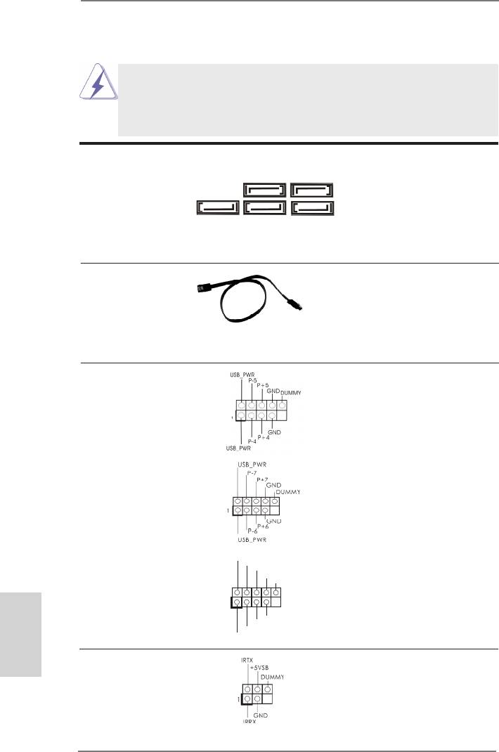
2.7 Onboard Headers and Connectors
Onboard headers and connectors are NOT jumpers. Do NOT place
jumper caps over these headers and connectors. Placing jumper caps
over the headers and connectors will cause permanent damage of the
motherboard!
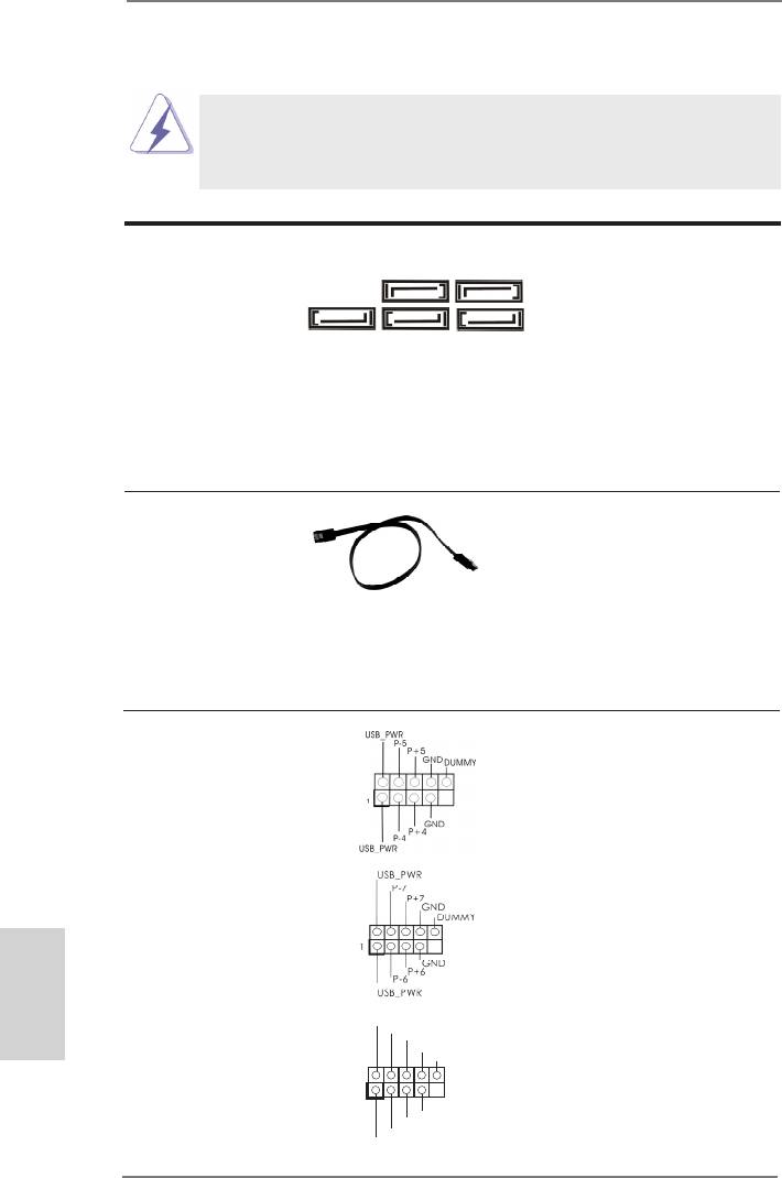
Serial ATA3 Connectors These ve Serial ATA3
(SATA3_1: see p.2, No. 17)
(SATA3) connectors support
SATA3_3 SATA3_1
(SATA3_2: see p.2, No. 18)
SATA data cables for internal
(SATA3_3: see p.2, No. 16)
storage devices. The current
(SATA3_4: see p.2, No. 19)
SATA3 interface allows up to
SATA3_5 SATA3_4 SATA3_2
(SATA3_5: see p.2, No. 20)
6.0 Gb/s data transfer rate.
Serial ATA (SATA) Either end of the SATA data
Data Cable cable can be connected to the
(Optional)
SATA / SATA2 / SATA3 hard
disk or the SATA3 connector on
this motherboard.
USB 2.0 Headers Besides four default USB 2.0
(9-pin USB_4_5)
ports on the I/O panel, there
(see p.2 No. 26)
are three USB 2.0 headers on
this motherboard. Each USB 2.0
header can support two USB
2.0 ports.
(9-pin USB_6_7)
(see p.2 No. 27)
U SB_PWR
(9-pin USB_8_9)
P-9
P +9
(see p.2 No. 28)
GND
DUMMY
1
English
GND
P +8
P-8
U SB_PWR
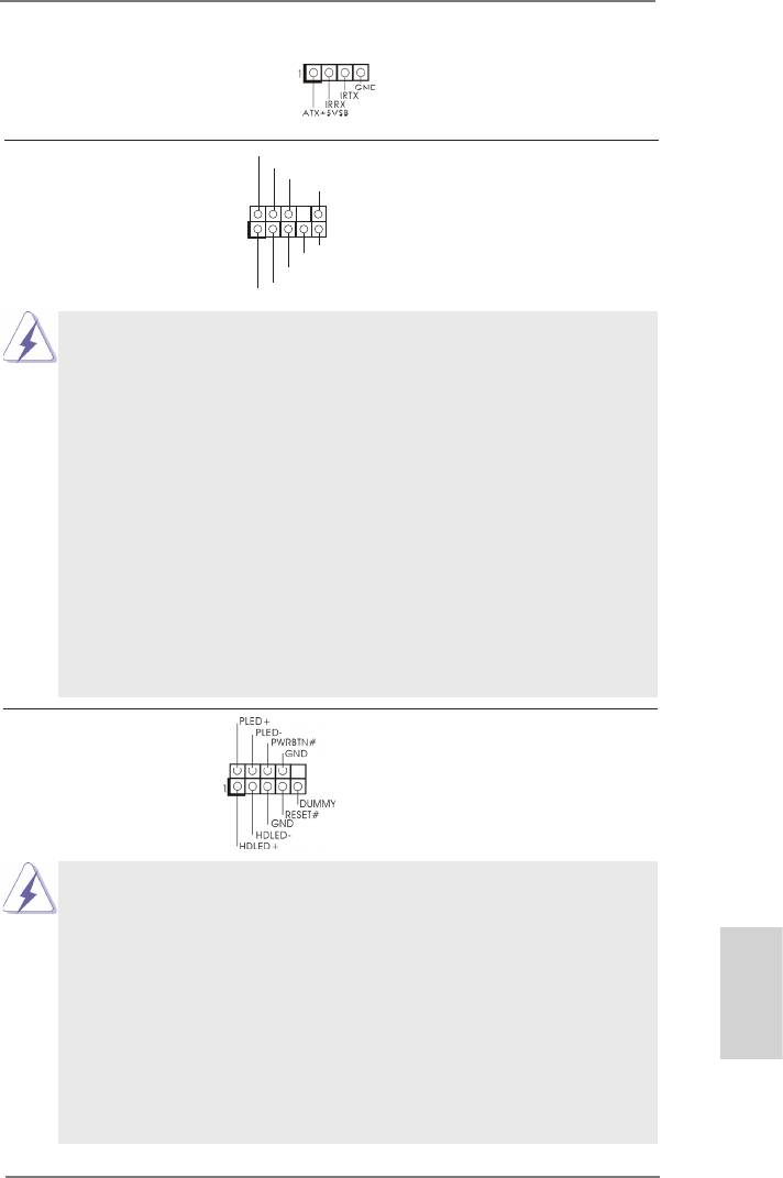
Infrared Module Header This header supports an
(5-pin IR1)
optional wireless transmitting
(see p.2 No. 29)
and receiving infrared module.
24
ASRock 970 Extreme3 R2.0 Motherboard
Consumer Infrared Module Header This header can be used to
(4-pin CIR1)
connect the remote
(see p.2 No. 25)
controller receiver.
GND
Front Panel Audio Header This is an interface for the front
P RESENCE#
M IC_RET
(9-pin HD_AUDIO1)
panel audio cable that allows
OUT_RET
(see p.2 No. 32)
convenient connection and
1
control of audio devices.
O UT2_L
J _SENSE
O UT2_R
M IC2_R
M IC2_L
1. High Denition Audio supports Jack Sensing, but the panel wire on
the chassis must support HDA to function correctly. Please follow the
instruction in our manual and chassis manual to install your system.
2. If you use AC’97 audio panel, please install it to the front panel audio
header as below:
A. Connect Mic_IN (MIC) to MIC2_L.
B. Connect Audio_R (RIN) to OUT2_R and Audio_L (LIN) to OUT2_L.
C. Connect Ground (GND) to Ground (GND).
D. MIC_RET and OUT_RET are for HD audio panel only. You don’t
need to connect them for AC’97 audio panel.
E. To activate the front mic.
®
For Windows
XP / XP 64-bit OS:
Select “Mixer”. Select “Recorder”. Then click “FrontMic”.
®
TM
TM
For Windows
8 / 8 64-bit / 7 / 7 64-bit / Vista
/ Vista
64-bit OS:
Go to the “FrontMic” Tab in the Realtek Control panel. Adjust
“Recording Volume”.
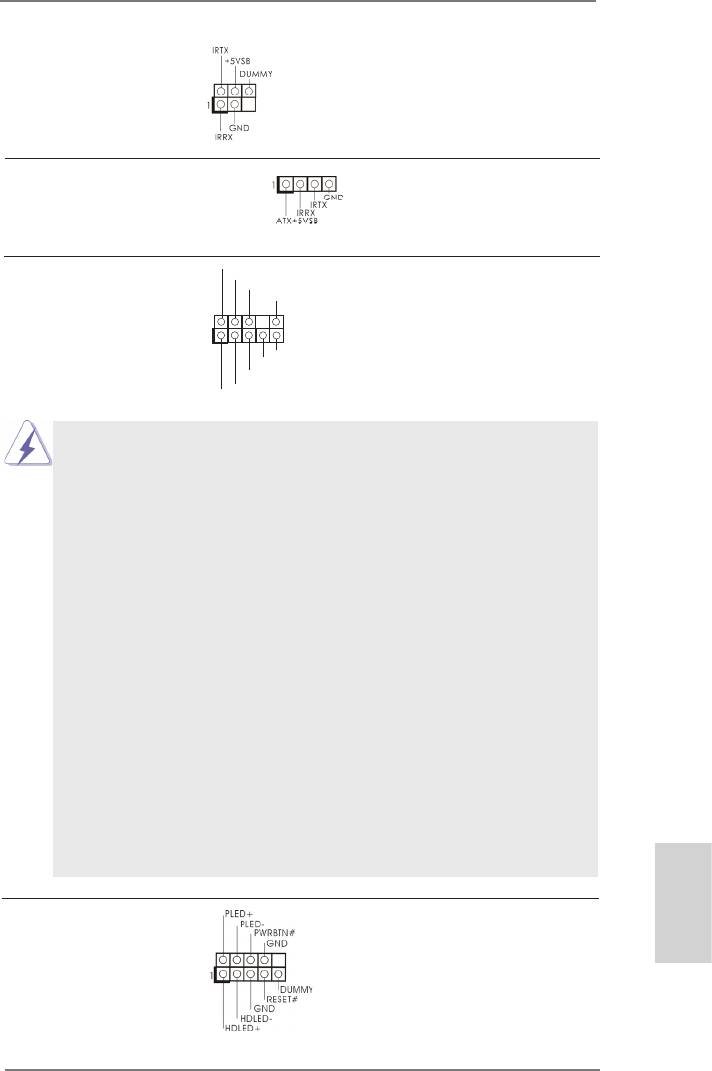
System Panel Header This header accommodates
(9-pin PANEL1)
several system front panel
(see p.2 No. 23)
functions.
Connect the power switch, reset switch and system status indicator
on the chassis to this header according to the pin assignments below.
Note the positive and negative pins before connecting the cables.
PWRBTN (Power Switch):
Connect to the power switch on the chassis front panel. You may con-
gure the way to turn off your system using the power switch.
English
RESET (Reset Switch):
Connect to the reset switch on the chassis front panel. Press the reset
switch to restart the computer if the computer freezes and fails to per-
form a normal restart.
25
ASRock 970 Extreme3 R2.0 Motherboard
PLED (System Power LED):
Connect to the power status indicator on the chassis front panel. The
LED is on when the system is operating. The LED keeps blinking
when the sys-tem is in S1 sleep state. The LED is off when the system
is in S3/S4 sleep state or powered off (S5).
HDLED (Hard Drive Activity LED):
Connect to the hard drive activity LED on the chassis front panel. The
LED is on when the hard drive is reading or writing data.
The front panel design may differ by chassis. A front panel module
mainly consists of power switch, reset switch, power LED, hard drive
activity LED, speaker and etc. When connecting your chassis front
panel module to this header, make sure the wire assignments and the
pin assign-ments are matched correctly.
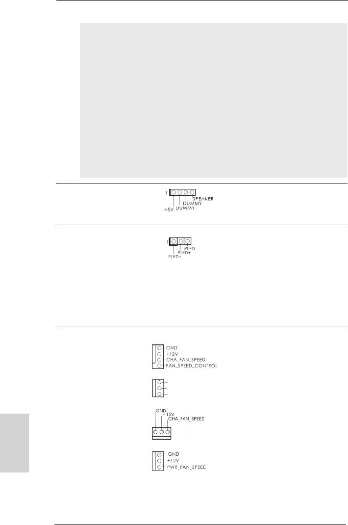
Chassis Speaker Header Please connect the chassis
(4-pin SPEAKER 1)
speaker to this header.
(see p.2 No. 24)
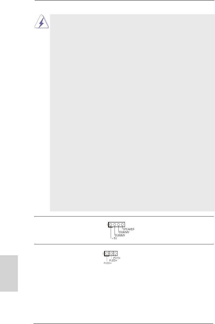
Power LED Header Please connect the chassis
(3-pin PLED1)
power LED to this header to
(see p.2 No. 22)
indicate system power status.
The LED is on when the system
is operating. The LED keeps
blinking in S1 state. The LED is
off in S3/S4 state or S5 state
(power off).
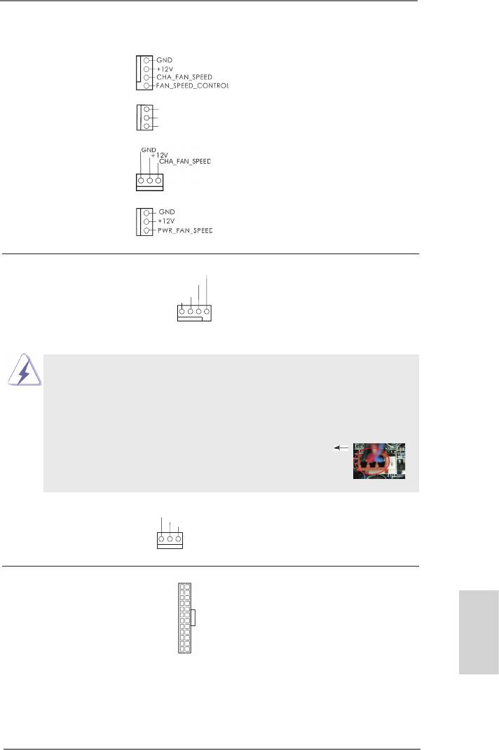
Chassis and Power Fan Connectors Please connect the fan cables
(4-pin CHA_FAN1)
to the fan connectors and
(see p.2 No. 12)
match the black wire to the
ground pin. CHA_FAN1/2/3 fan
(3-pin CHA_FAN2)
GND
speed can be controlled through
+ 12V
(see p.2 No. 15)
CHA_FAN_SPEED
UEFI or AXTU.
(3-pin CHA_FAN3)
English
(see p.2 No. 2)
(3-pin PWR_FAN1)
(see p.2 No. 10)
26
ASRock 970 Extreme3 R2.0 Motherboard
CPU Fan Connectors Please connect the CPU fan
FAN_S PEED_CONTROL
CPU_FAN_SPEED
(4-pin CPU_FAN1)
cable to the connector and
+ 12V
GND
(see p.2 No. 6)
match the black wire to the
ground pin.
1 2 3 4
Though this motherboard provides 4-Pin CPU fan (Quiet Fan) support, the 3-Pin
CPU fan still can work successfully even without the fan speed control function.
If you plan to connect the 3-Pin CPU fan to the CPU fan connector on this
motherboard, please connect it to Pin 1-3.
Pin 1-3 Connected
3-Pin Fan Installation
GND
(3-pin CPU_FAN2)
+ 12V
CPU_FAN_SPEED
(see p.2 No. 5)
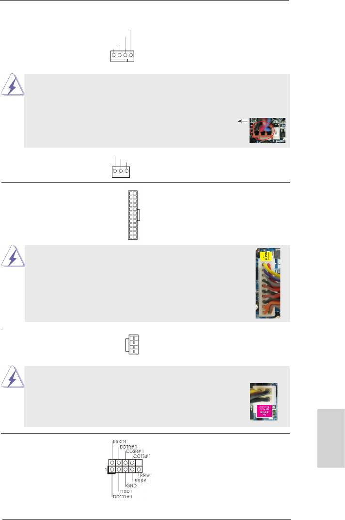
ATX Power Connector Please connect an ATX power
12
24
(24-pin ATXPWR1)
supply to this connector.
(see p.2 No. 9)
1
13
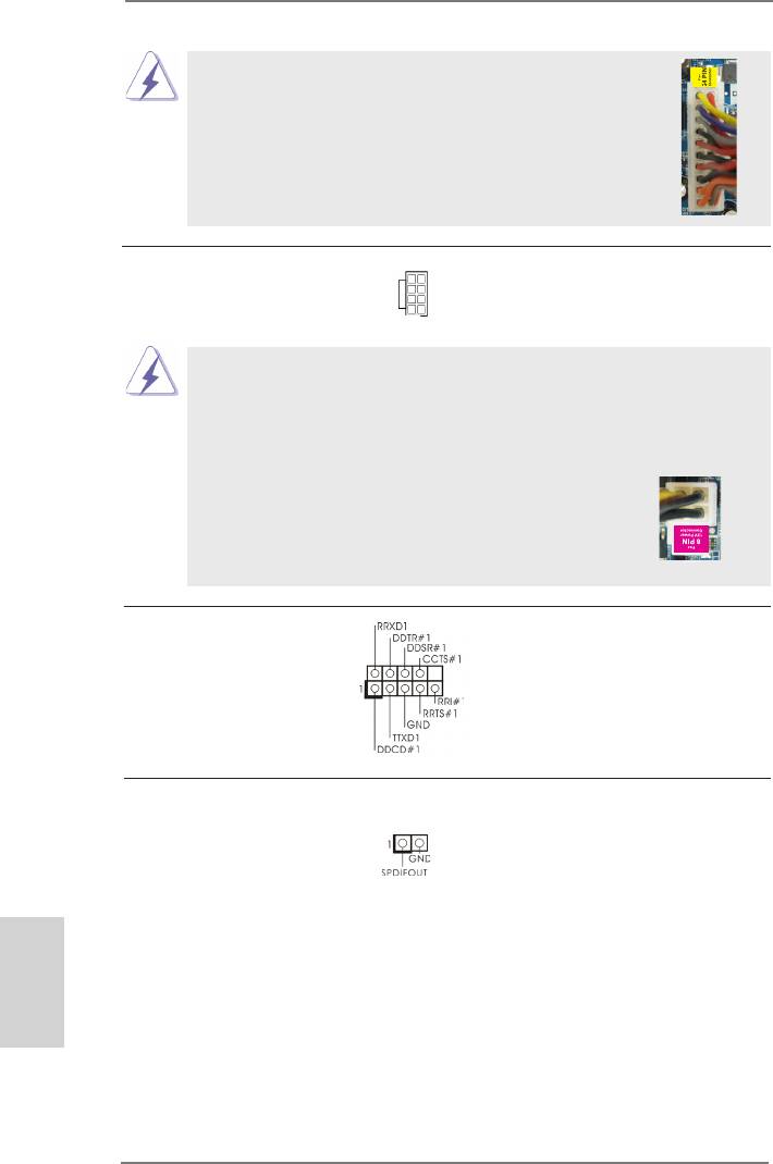
Though this motherboard provides 24-pin ATX power connector,
12
24
it can still work if you adopt a traditional 20-pin ATX power supply.
To use the 20-pin ATX power supply, please plug your power
supply along with Pin 1 and Pin 13.
20-Pin ATX Power Supply Installation
1
13
ATX 12V Power Connector Please connect an ATX 12V
5 1
(8-pin ATX12V1)
power supply to this connector.
(see p.2 No. 1)
8 4
Though this motherboard provides 8-pin ATX 12V power connector, it can still work
if you adopt a traditional 4-pin ATX 12V power supply. To use the
5 1
4-pin ATX power supply, please plug your power supply along with
Pin 1 and Pin 5.
8 4
4-Pin ATX 12V Power Supply Installation
Serial port Header This COM1 header supports a
(9-pin COM1)
serial port module.
English
(see p.2 No.30)
27
ASRock 970 Extreme3 R2.0 Motherboard
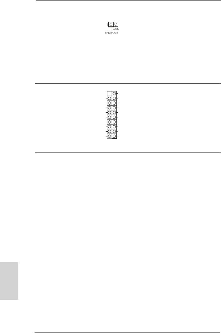
HDMI_SPDIF Header HDMI_SPDIF header, providing
(2-pin HDMI_SPDIF1)
SPDIF audio output to HDMI
(
see p.2 No. 31)
VGA card, allows the system to
connect HDMI Digital TV/
projector/LCD devices. Please
connect the HDMI_SPDIF
connector of HDMI VGA card to
this header.
USB 3.0 Header Besides two default USB 3.0
VbusVbus
(19-pin USB3_2_3)
ports on the I/O panel, there is
Vbus
IntA_P3_SSRX-
IntA_P2_SSRX-
IntA_P3_SSRX+
(see p.2 No. 38)
one USB 3.0 header on this
IntA_P2_SSRX+
GND
motherboard. This USB 3.0
GND
IntA_P3_SSTX-
IntA_P2_SSTX-
IntA_P3_SSTX+
header can support two USB 3.0
IntA_P2_SSTX+
GND
ports.
GND
IntA_P3_D-
IntA_P2_D-
IntA_P3_D+
IntA_P2_D+
DUMMY
2.8 Driver Installation Guide
To install the drivers to your system, please insert the support CD to your optical
drive rst. Then, the drivers compatible to your system can be auto-detected and
listed on the support CD driver page. Please follow the order from up to bottom side
to install those required drivers. Therefore, the drivers you install can work properly.
®
TM
2.9 Installing Windows
8 / 8 64-bit / 7 / 7 64-bit / Vista
/
TM
Vista
64-bit / XP / XP 64-bit With RAID Functions
®
TM
TM
If you want to install Windows
8 / 8 64-bit / 7 / 7 64-bit / Vista
/ Vista
64-bit / XP
/ XP 64-bit on your SATA3 HDDs with RAID functions, please refer to the document
at the following path in the Support CD for detailed procedures:
..\ RAID Installation Guide
English
®
TM
2.10 Installing Windows
8 / 8 64-bit / 7 / 7 64-bit / Vista
/
TM
Vista
64-bit / XP / XP 64-bit Without RAID Functions
®
TM
TM
If you want to install Windows
8 / 8 64-bit / 7 / 7 64-bit / Vista
/ Vista
64-bit / XP
/ XP 64-bit OS on your SATA3 HDDs without RAID functions, please follow below
procedures according to the OS you install.
28
ASRock 970 Extreme3 R2.0 Motherboard
®
2.10.1 Installing Windows
XP / XP 64-bit Without RAID
Functions
®
If you want to install Windows
XP / XP 64-bit on your SATA3 HDDs without RAID
functions, please follow below steps.
Using SATA3 HDDs without NCQ and Hot Plug functions (IDE mode)
STEP 1: Set up UEFI.
A. Enter UEFI SETUP UTILITY Advanced screen Storage Conguration.
B. Set the “SATA Mode” option to [IDE].
®
STEP 2: Install Windows
XP / XP 64-bit OS on your system.
®
TM
2.10.2 Installing Windows
8 / 8 64-bit / 7 / 7 64-bit / Vista
/
TM
Vista
64-bit Without RAID Functions
®
TM
TM
If you want to install Windows
8 / 8 64-bit / 7 / 7 64-bit / Vista
/ Vista
64-bit on
your SATA3 HDDs without RAID functions, please follow below steps.
Using SATA3 HDDs without NCQ and Hot Plug functions (IDE mode)
STEP 1: Set up UEFI.
A. Enter UEFI SETUP UTILITY Advanced screen Storage Conguration.
B. Set the “SATA Mode” option to [IDE].
®
TM
TM
STEP 2: Install Windows
8 / 8 64-bit / 7 / 7 64-bit / Vista
/ Vista
64-bit OS on
your system.
Using SATA3 HDDs with NCQ and Hot Plug functions (AHCI mode)
STEP 1: Set up UEFI.
A. Enter UEFI SETUP UTILITY Advanced screen Storage Conguration.
B. Set the “SATA Mode” option to [AHCI].
®
TM
TM
STEP 2: Install Windows
8 / 8 64-bit / 7 / 7 64-bit / Vista
/ Vista
64-bit OS on
your system.
English
29
ASRock 970 Extreme3 R2.0 Motherboard

3. BIOS Information
The Flash Memory on the motherboard stores BIOS Setup Utility. When you start up
the computer, please press <F2> or <Del> during the Power-On-Self-Test (POST)
to enter BIOS Setup utility; otherwise, POST continues with its test routines. If you
wish to enter BIOS Setup after POST, please restart the system by pressing <Ctl>
+ <Alt> + <Delete>, or pressing the reset button on the system chassis. The BIOS
Setup program is designed to be user-friendly. It is a menu-driven program, which
allows you to scroll through its various sub-menus and to select among the prede-
termined choices. For the detailed information about BIOS Setup, please refer to the
User Manual (PDF le) contained in the Support CD.
4. Software Support CD information
®
®
This motherboard supports various Microsoft
Windows
operating systems: 8 / 8
TM
TM
64-bit / 7 / 7 64-bit / Vista
/ Vista
64-bit / XP / XP 64-bit. The Support CD that
came with the motherboard contains necessary drivers and useful utilities that will
enhance motherboard features. To begin using the Support CD, insert the CD into
your CD-ROM drive. It will display the Main Menu automatically if “AUTORUN” is
enabled in your computer. If the Main Menu does not appear automatically, locate
and double-click on the le “ASSETUP.EXE” from the BIN folder in the Support CD
to display the menus.
English
30
ASRock 970 Extreme3 R2.0 Motherboard
1. Einführung
Wir danken Ihnen für den Kauf des ASRock 970 Extreme3 R2.0 Motherboard, ein
zuverlässiges Produkt, welches unter den ständigen, strengen Qualitätskontrollen
von ASRock gefertigt wurde. Es bietet Ihnen exzellente Leistung und robustes De-
sign, gemäß der Verpichtung von ASRock zu Qualität und Halbarkeit. Diese Sch-
nellinstallationsanleitung führt in das Motherboard und die schrittweise Installation
ein. Details über das Motherboard nden Sie in der Bedienungsanleitung auf der
Support-CD.
Da sich Motherboard-Spezikationen und BIOS-Software verändern
können, kann der Inhalt dieses Handbuches ebenfalls jederzeit geändert
werden. Für den Fall, dass sich Änderungen an diesem Handbuch
ergeben, wird eine neue Version auf der ASRock-Website, ohne weitere
Ankündigung, verfügbar sein. Die neuesten Grakkarten und unterstützten
CPUs sind auch auf der ASRock-Website aufgelistet.
ASRock-Website: http://www.asrock.com
Wenn Sie technische Unterstützung zu Ihrem Motherboard oder spezische
Informationen zu Ihrem Modell benötigen, besuchen Sie bitte unsere
Webseite:
www.asrock.com/support/index.asp
1.1 Kartoninhalt
ASRock 970 Extreme3 R2.0 Motherboard (ATX-Formfaktor)
ASRock 970 Extreme3 R2.0 Schnellinstallationsanleitung
ASRock 970 Extreme3 R2.0 Support-CD
Zwei Serial ATA (SATA) -Datenkabel (optional)
Ein I/O Shield
ASRock erinnert...
®
TM
Zur besseren Leistung unter Windows
8 / 8 64 Bit / 7 / 7 64 Bit / Vista
TM
/ Vista
64 Bit empfehlen wir, die Speicherkonguration im BIOS auf den
AHCI-Modus einzustellen. Hinweise zu den BIOS-Einstellungen nden
Sie in der Bedienungsanleitung auf der mitgelieferten CD.
Deutsch
31
ASRock 970 Extreme3 R2.0 Motherboard
1.2 Spezikationen
Plattform - ATX-Formfaktor
- Alle Feste Kondensatordesign (100% in Japan gefertigte,
erstklassige leitfähige Polymer-Kondensatoren)
CPU - Unterstützung von Socket AM3+-Prozessoren
- Unterstützung von Socket AM3-Prozessoren: AMD
TM
Phenom
II X6 / X4 / X3 / X2 (außer 920 / 940) / Athlon X4 /
X3 / X2 / Sempron-Prozessor
- Acht-Kern-CPU-bereit
- Unterstützt UCC (Unlock CPU Core)
- Digi Power-Design
- 4 + 1-Stromphasendesign
- Unterstützt CPU bis 140W
TM
- Unterstützt Cool ‘n’ Quiet
-Technologie von AMD
- FSB 2400 MHz (4.8 GT/s)
- Unterstützt Untied-Übertaktungstechnologie
- Unterstützt Hyper-Transport- 3.0 Technologie (HT 3.0)
Chipsatz - Northbridge: AMD 970
- Southbridge: AMD SB950
Speicher - Unterstützung von Dual-Kanal-Speichertechnologie
- 4 x Steckplätze für DDR3
- Unterstützt DDR3 2100+(OC)1866(OC)/1800(OC)/1600
(OC)/1333/1066/800 non-ECC, ungepufferter Speicher
- Max. Kapazität des Systemspeichers: 32GB
Erweiterungs- - 2 x PCI-Express-2.0-x16-Steckplätze
Steckplätze (PCIE2: x16-Modus; PCIE4: x4-Modus)
- 2 x PCI Express 2.0 x1-Steckplätze
- 2 x PCI -Steckplätze
TM
TM
TM
- Unterstützt AMD
Quad CrossFireX
und CrossFireX
Audio - 7.1
CH HD Audio mit dem Inhalt Schutz
(Realtek ALC892 Audio Codec)
- Premium Blu-ray-Audio-Unterstützung
Deutsch
LAN - PCIE x1 Gigabit LAN 10/100/1000 Mb/s
- Realtek RTL8111E
- Unterstützt Wake-On-LAN
- Unterstützt LAN-Kabelerkennung
- Unterstützt energieefzientes Ethernet 802.3az
- Unterstützt PXE
32
ASRock 970 Extreme3 R2.0 Motherboard

E/A-Anschlüsse I/O Panel
an der - 1 x PS/2-Mausanschluss
Rückseite - 1 x PS/2-Tastaturanschluss
- 1 x Koaxial-SPDIF-Ausgang
- 1 x optischer SPDIF-Ausgang
- 4 x Standard-USB 2.0-Anschlüsse
- 2 x Standard-USB 3.0-Anschlüsse
- 1 x eSATA3-Anschluss
- 1 x RJ-45 LAN Port mit LED (ACT/LINK LED und SPEED
LED)
- HD Audiobuchse: Lautsprecher seitlich / Lautsprecher
hinten / Mitte/Bass / Audioeingang/ Lautsprecher vorne /
Mikrofon
SATA3 - 5 x SATA 3-Anschluss mit 6,0 Gb/s, unterstützt RAID-
(RAID 0, RAID 1, RAID 5 und RAID 10), NCQ-, AHCI- und
„Hot Plugging“-Funktionen
USB3.0 - 2 x USB 3.0-Ports an der Rückseite durch Etron EJ188H,
unterstützt USB 1.1/2.0/3.0 mit bis zu 5 Gb/s
- 1 x USB 3.0-Header (unterstützt zwei USB 3.0-Ports) an der
Vorderseite durch Etron EJ188H, unterstützt USB 1.1/2.0/3.0
mit bis zu 5 Gb/s
Anschlüsse - 5 x SATA3 6,0 GB/s-Anschlüsse
- 1 x Infrarot-Modul-Header
- 1 x Consumer Infrarot-Modul-Header
- 1 x COM-Anschluss-Header
- 1 x HDMI_SPDIF-Anschluss
- 1 x Betriebs-LED-Header
- 2 x CPUlüfter-Anschluss (1 x 4-pin, 1 x 3-pin)
- 3 x Gehäuselüfter-Anschluss (1 x 4-pin, 2 x 3-pin)
- 1 x Stromlüfter-Anschluss (3-pin)
- 24-pin ATX-Netz-Header
- 8-pin anschluss für 12V-ATX-Netzteil
- Anschluss für Audio auf der Gehäusevorderseite
- 3 x USB 2.0-Anschlüsse (Unterstützung 6 zusätzlicher
USB 2.0-Anschlüsse)
- 1 x USB 3.0-Anschlüsse (Unterstützung 2 zusätzlicher
USB 3.0-Anschlüsse)
Deutsch
BIOS - 32Mb AMIs Legal BIOS UEFI mit GUI-Unterstützung
- Unterstützung für “Plug and Play”
- ACPI 1.1-Weckfunktionen
- JumperFree-Modus
33
ASRock 970 Extreme3 R2.0 Motherboard
- SMBIOS 2.3.1
- CPU, VCCM, NB, SB Stromspannung Multianpassung
Support-CD - Treiber, Dienstprogramme, Antivirussoftware
(Probeversion), CyberLink MediaEspresso 6.5-Testversion,
Google Chrome Browser und Toolbar
Hardware Monitor - CPU-Temperatursensor
- Motherboardtemperaturerkennung
- Drehzahlmessung für CPU/Gehäuse/Stromlüfter
- CPU-/Gehäuselüftergeräuschdämpfung
- Mehrstuge Geschwindigkeitsteuerung für CPU-/
Gehäuselüfter
- Spannungsüberwachung: +12V, +5V, +3.3V, Vcore
®
®
Betriebssysteme - Unterstützt Microsoft
Windows
8 / 8 64-Bit / 7 / 7 64-Bit /
TM
TM
Vista
/ Vista
64-Bit / XP / XP 64-Bit
Zertizierungen - FCC, CE, WHQL
- Gemäß Ökodesign-Richtlinie (ErP/EuP) (Stromversorgung
gemäß Ökodesign-Richtlinie (ErP/EuP) erforderlich)
* Für die ausführliche Produktinformation, besuchen Sie bitte unsere Website:
http://www.asrock.com
Deutsch
34
ASRock 970 Extreme3 R2.0 Motherboard
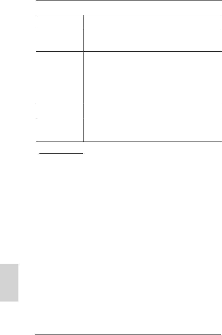
1.3 Einstellung der Jumper
Die Abbildung verdeutlicht, wie Jumper
gese tzt werde n. Wer den Pins dur ch
Jumperkappen verdeckt, ist der Jumper
“gebrückt”. Werden keine Pins durch Jump-
erkappen verdeckt, ist der Jumper “offen”.
Die Abbildung zeigt einen 3-Pin Jumper
dessen Pin1 und Pin2 “gebrückt” sind, bzw.
es befindet sich eine Jumper-Kappe auf
diesen beiden Pins.
Jumper Einstellun
CMOS löschen
(CLRCMOS1, 3-Pin jumper)
(siehe S.2, No. 21)
Default-
CMOS
Einstellung
löschen
Hinweis: CLRCMOS1 erlaubt Ihnen das Löschen der CMOS-Daten. Diese beinhal-
ten das System-Passwort, Datum, Zeit und die verschiedenen BIOS-Para-
meter. Um die Systemparameter zu löschen und auf die Werkseinstellung
zurückzusetzen, schalten Sie bitte den Computer ab und entfernen das
Stromkabel. Benutzen Sie eine Jumperkappe, um die
Pin 2 und Pin 3 an CLRCMOS1 für 5 Sekunden kurzzuschließen. Bitte
vergessen Sie nicht, den Jumper wieder zu entfernen, nachdem das
CMOS gelöscht wurde. Bitte vergessen Sie nicht, den Jumper wieder zu
entfernen, nachdem das CMOS gelöscht wurde. Wenn Sie den CMOS-
Inhalt gleich nach dem Aktualisieren des BIOS löschen müssen, müssen
Sie zuerst das System starten und dann wieder ausschalten, bevor Sie
den CMOS-Inhalt löschen.
Deutsch
35
ASRock 970 Extreme3 R2.0 Motherboard
1.4 Anschlüsse
Anschlussleisten sind KEINE Jumper. Setzen Sie KEINE Jumperkappen
auf die Pins der Anschlussleisten. Wenn Sie die Jumperkappen auf die
Anschlüsse setzen, wird das Motherboard permanent beschädigt!
Anschluss Beschreibung
Seriell-ATA3-Anschlüsse Diese fünf Serial ATA3-
(SATA3_1: siehe S.2 - No. 17)
(SATA3-)Verbínder
SATA3_3 SATA3_1
(SATA3_2: siehe S.2 - No. 18)
unterstützten SATA-Datenkabel
(SATA3_3: siehe S.2 - No. 16)
für interne
SATA3_5 SATA3_4 SATA3_2
(SATA3_4: siehe S.2 - No. 19)
Massenspeichergeräte. Die
(SATA3_5: siehe S.2 - No. 20)
aktuelle SATA3- Schnittstelle
ermöglicht eine
Datenübertragungsrate bis
6,0 Gb/s.
Serial ATA- (SATA-) SJedes Ende des SATA
Datenkabel Datenkabels kann an die
(Option)
SATA / SATAII / SATA3
Festplatte oder das SATA3
Verbindungsstück auf dieser
Hauptplatine angeschlossen
werden.
USB 2.0-Header Zusätzlich zu den vier
(9-pol. USB_4_5)
üblichen USB 2.0-Ports an den
(siehe S.2 - No. 26)
I/O-Anschlüssen benden sich
drei USB 2.0-
Anschlussleisten am
Motherboard. Pro USB 2.0-
(9-pol. USB_6_7)
Anschlussleiste werden zwei
(siehe S.2 - No. 27)
USB 2.0-Ports unterstützt.
Deutsch
(9-pol. USB_8_9)
U SB_PWR
P-9
(siehe S.2 - No. 28)
P +9
GND
DUMMY
1
GND
P +8
P-8
U SB_PWR
36
ASRock 970 Extreme3 R2.0 Motherboard
Infrarot-Modul-Header Dieser Header unterstützt ein
(5-pin IR1)
optionales, drahtloses Sende-
(siehe S.2 - No. 29)
und Empfangs-Infrarotmodul.
Consumer Infrared-Modul-Header Dieser Header kann zum
(4-pin CIR1)
Anschließen Remote-
(siehe S.2 - No. 25)
Empfänger.
GND
Anschluss für Audio auf Dieses Interface zu einem
P RESENCE#
M IC_RET
der Gehäusevorderseite Audio-Panel auf der Vorder
OUT_RET
(9-Pin HD_AUDIO1)
seite Ihres Gehäuses,
1
(siehe S.2 - No. 32)
ermöglicht Ihnen eine bequeme
O UT2_L
J _SENSE
Anschlussmöglichkeit und
O UT2_R
M IC2_R
Kontrolle über Audio-Geräte.
M IC2_L
1. High Denition Audio unterstützt Jack Sensing (automatische Erkennung
falsch angeschlossener Geräte), wobei jedoch die Bildschirmverdrahtung
am Gehäuse HDA unterstützen muss, um richtig zu funktionieren.
Beachten Sie bei der Installation im System die Anweisungen in unserem
Handbuch und im Gehäusehandbuch.
2. Wenn Sie die AC’97-Audioleiste verwenden, installieren Sie diese wie
nachstehend beschrieben an der Front-Audioanschlussleiste:
A. Schließen Sie Mic_IN (MIC) an MIC2_L an.
B. Schließen Sie Audio_R (RIN) an OUT2_R und Audio_L (LIN) an OUT2_L an.
C. Schließen Sie Ground (GND) an Ground (GND) an.
D. MIC_RET und OUT_RET sind nur für den HD-Audioanschluss gedacht. Diese
Anschlüsse müssen nicht an die AC’97-Audioleiste angeschlossen werden.
E. So aktivieren Sie das Mikrofon an der Vorderseite.
®
Bei den Betriebssystemen Windows
XP / XP 64 Bit:
Wählen Sie „Mixer“. Wählen Sie „Recorder“ (Rekorder). Klicken Sie dann
auf „FrontMic“ (Vorderes Mikrofon).
®
TM
TM
Bei den Betriebssystemen Windows
8 / 8 64 Bit / 7 / 7 64 Bit / Vista
/ Vista
64 Bit:
Wählen Sie im Realtek-Bedienfeld die „FrontMic“ (Vorderes Mikrofon)-
Registerkarte. Passen Sie die „Recording Volume“ (Aufnahmelautstärke)
an.
System Panel-Header Dieser Header unterstützt
(9-pin PANEL1)
Deutsch
mehrere Funktion der
(siehe S.2 - No. 23)
Systemvorderseite.
37
ASRock 970 Extreme3 R2.0 Motherboard
Schließen Sie die Ein-/Austaste, die Reset-Taste und die
Systemstatusanzeige am Gehäuse an diesen Header an; befolgen Sie
dabei die nachstehenden Hinweise zur Pinbelegung. Beachten Sie die
positiven und negativen Pins, bevor Sie die Kabel anschließen.
PWRBTN (Ein-/Ausschalter):
Zum Anschließen des Ein-/Ausschalters an der Frontblende des Gehäu
ses. Sie können kongurieren, wie das System mit Hilfe des
Ein-/Ausschalters ausgeschaltet werden können soll.
RESET (Reset-Taste):
Zum Anschließen der Reset-Taste an der Frontblende des Gehäuses.
Mit der Reset-Taste können Sie den Computer im Falle eines Absturzes
neu starten.
PLED (Systembetriebs-LED):
Zum Anschließen der Betriebsstatusanzeige an der Frontblende des
Gehäuses. Die LED leuchtet, wenn das System in Betrieb ist. Die LED
blinkt, wenn sich das System im Ruhezustand S1 bendet. Die LED
schaltet sich aus, wenn sich das System in den Modi S3/S4 bendet
oder ausgeschaltet ist (S5).
HDLED (Festplattenaktivitäts-LED):
Zum Anschließen der Festplattenaktivitäts-LED an der Frontblende des
Gehäuses. Die LED leuchtet, wenn die Festplatte Daten liest oder
schreibt.
Das Design der Frontblende kann je nach Gehäuse variiere. Ein
Frontblendenmodul besteht hauptsächlich aus einer Ein-/Austaste, einer
Reset-Taste, einer Betriebs-LED, einer Festplattenaktivitäts-LED,
Lautsprechern, etc. Stellen Sie beim Anschließen des
Frontblendenmoduls Ihres Gehäuses an diesem Header sicher, dass die
Kabel- und Pinbelegung korrekt übereinstimmen.
Gehäuselautsprecher-Header Schließen Sie den
(4-pin SPEAKER1)
Gehäuselautsprecher an
(siehe S.2 - No. 24)
diesen Header an.
Betriebs-LED-Header Bitte schließen Sie die
(3-pin PLED1)
Betriebs-LED des Gehäuses
Deutsch
(siehe S.2 - No. 22)
zur Anzeige des
Systembetriebsstatus an
diesem Header an. Die LED
leuchtet, wenn das System in
Betrieb ist. Die LED blinkt im
S1-Zustand. Im S3-/S4- oder
S5-Zustand (ausgeschaltet)
leuchtet die LED nicht.
38
ASRock 970 Extreme3 R2.0 Motherboard
Gehäuse- und Stromlüfteranschlüsse Verbinden Sie die Lüfterkabel
(4-pin CHA_FAN1)
mit den Lüfteranschlüssen,
(siehe S.2, No. 12)
wobei der schwarze Draht an
den Schutzleiterstift
(3-pin CHA_FAN2)
GND
angeschlossenwird. CHA_
+ 12V
(siehe S.2 - No. 15)
CHA_FAN_SPEED
FAN1/2/3-Lüftergeschwindigkeit
kann über UEFI oder AXTU
(3-pin CHA_FAN3)
gesteuert werden.
(siehe S.2 - No. 2)
(3-pin PWR_FAN1)
(siehe S.2 - No. 10)
CPU-Lüfteranschluss Verbinden Sie das CPU -
FAN_S PEED_CONTROL
(4-pin CPU_FAN1)
CPU_FAN_SPEED
Lüfterkabel mit diesem
+ 12V
(siehe S.2 - No. 6)
Anschluss und passen Sie den
GND
schwarzen Draht dem
1 2 3 4
Erdungsstift an.
Obwohl dieses Motherboard einen vierpoligen CPU-Lüfteranschluss
(Quiet Fan) bietet, können auch CPU-Lüfter mit dreipoligem Anschluss
angeschlossen werden; auch ohne Geschwindigkeitsregulierung. Wenn
Sie einen dreipoligen CPU-Lüfter an den CPU-Lüferanschluss dieses
Motherboards anschließen möchten, verbinden Sie ihn bitte mit den
Pins 1 – 3.
Pins 1–3 anschließen
Lüfter mit dreipoligem Anschluss installieren
(3-pin CPU_FAN2)
GND
+ 12V
(siehe S.2 - No. 5)
CPU_FAN_SPEED
ATX-Netz-Header Verbinden Sie die ATX-
12
24
(24-pin ATXPWR1)
Stromversorgung mit diesem
(siehe S.2 - No. 9)
Header.
1
13
Deutsch
39
ASRock 970 Extreme3 R2.0 Motherboard
Obwohl dieses Motherboard einen 24-pol. ATX-
12
24
Stromanschluss bietet, kann es auch mit einem
modizierten traditionellen 20-pol. ATX-Netzteil
verwendet werden. Um ein 20-pol. ATX-Netzteil zu
verwenden, stecken Sie den Stecker mit Pin 1 und
Pin 13 ein.
Installation eines 20-pol. ATX-Netzteils
1
13
ATX 12V Anschluss Bitte schließen Sie an diesen
5 1
(8-pin ATX12V1)
Anschluss die ATX 12V
(siehe S.2 - No. 1)
Stromversorgung an.
8 4
Obwohl diese Hauptplatine 8-Pin ATX 12V Stromanschluss zur
Verfügung stellt, kann sie noch arbeiten, wenn Sie einen
traditionellen 4-Pin ATX 12V Energieversorgung adoptieren. Um die
4-Pin ATX Energieversorgung zu verwenden, stecken Sie bitte Ihre
Energieversorgung zusammen mit dem Pin 1 und Pin 5 ein.
5 1
8 4
Installation der 4-Pin ATX 12V Energieversorgung
COM-Anschluss-Header Dieser COM-Anschluss-
(9-pin COM1)
Header wird verwendet, um
(siehe S.2 - No. 30)
ein COM-Anschlussmodul zu
unterstützen.
HDMI_SPDIF-Anschluss Der HDMI_SPDIF-Anschluss
(2-pin HDMI_SPDIF1)
stellt einen SPDIF-
(siehe S.2 - No. 31)
Audioausgang für eine HDMI-
VGA-Karte zur Verfügung und
ermöglicht den Anschluss von
HDMI-Digitalgeräten wie
Deutsch
Fernsehgeräten, Projektoren,
LCD-Geräten an das System.
Bitte verbinden Sie den
HDMI_SPDIF-Anschluss der
HDMI-VGA-Karte mit diesem
Anschluss.
40
ASRock 970 Extreme3 R2.0 Motherboard


