Siemens HB78G1590S: Connecting the appliance to the power supply Securing the appliance
Connecting the appliance to the power supply Securing the appliance: Siemens HB78G1590S
Table of contents
- Preparing the units - Fig. 1
- Connecting the appliance to the power supply Securing the appliance
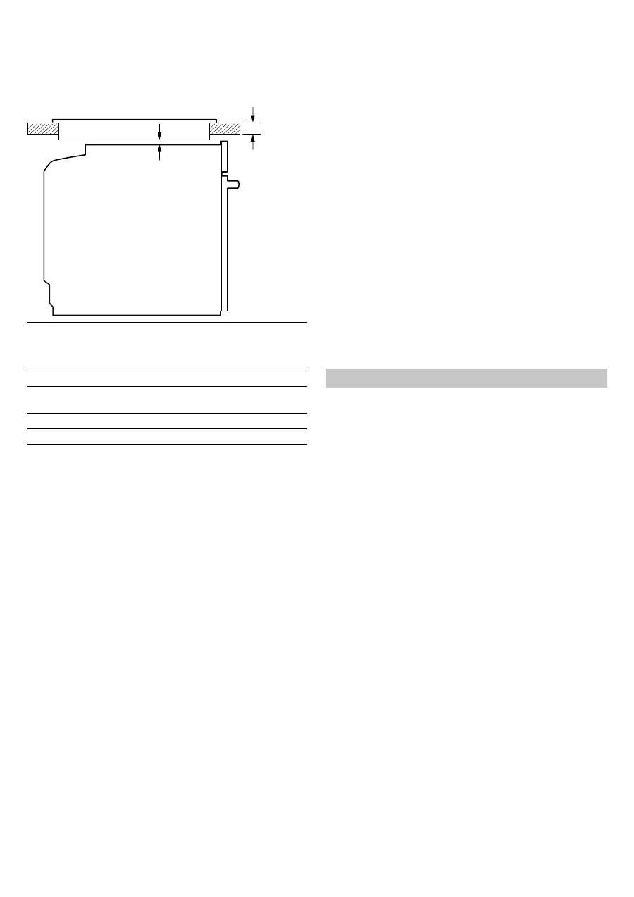
Appliance under worktop – Fig. 1
To ventilate the appliance, the intermediate floor must have a
ventilation cut-out.
Secure the worktop to the fitted units.
If the appliance is installed under a hob, the following minimum
dimensions must be adhered to (including substructure, if
applicable):
The minimum worktop thickness
a
results from the minimum
required dimension
b
.
Observe the installation instructions for the hob.
Appliance in a tall unit
Figs 2+4
The appliance may also be installed in a tall unit.
There must be a gap between the intermediate floors and the
mounting wall of approx. 20 mm in order to provide ventilation
to the oven.
Only fit the appliance at a height where removing baking trays
does not present a problem.
Corner installation
Fig. 3
To ensure that the appliance door can be opened in the case of
corner installation, take account of dimension
D
. Dimension
E
is
dependent on the thickness of the unit front under the handle.
Connecting the appliance to the power supply
The appliance corresponds to protection class I and may only
be operated with a protective earth connection.
The appliance must be disconnected from the power supply for
all installation work.
The appliance must only be connected with the power cable
provided. Connect the power cable to the back of the appliance
(listen for the click).
A longer power cable can be obtained from the after-sales
service.
The power cable may only be replaced by a cable from the
original manufacturer, obtainable via the after-sales service.
Contact protection must be ensured by the installation.
Power cable with a plug with earthing contact
The appliance must only be connected to a properly installed
protective contact socket.
If the plug is no longer accessible following installation, an all-
pole isolating switch must be present on the installation side
with a contact gap of at least 3 mm.
Power cable without a plug with earthing contact
Only allow a licenced professional to connect the appliance. He
is subject to the regulations of the local electricity provider.
An all-pole isolating switch with at least a 3 mm contact gap
must be fitted in the installation. Identify the phase and neutral
(zero) conductor in the connection socket. Incorrect connection
may cause damage to the appliance.
only connect as per the connection diagram. See the rating
plate for the voltage. Connect the wires of the mains power
cable according to the colour coding: green/yellow = PE
conductor
<
, blue = neutral conductor, brown = phase (external
conductor).
UK and Australia only
Connect using at least a 16 A plug or protect with a 16 A fuse.
Only in Sweden, Finland and Norway
The appliance can also be connected using the plug provided
which has an earthing contact system. This must still be
accessible after installation. If this is not the case, an all-pole
isolating switch must be used on the installation side with a
contact gap of at least 3 mm.
Securing the appliance
Fig. 5
■
If necessary, fit the spacer.
■
Fully insert the appliance and centre it.
■
Screw the appliance into place.
■
The gap between the worktop and the appliance must not be
closed by additional battens.
Removal
Disconnect the appliance from the power supply. Undo the
securing screws. Raise the appliance slightly and pull it out
completely.
fr
Þ
Notice de montage
Préparation du meuble - fig. 1
■
Uniquement une installation effectuée selon cette notice de
montage garantit une utilisation en toute sécurité. En cas de
dommages résultant d'une installation incorrecte, l'installateur
est responsable.
■
Les meubles d'encastrement doivent résister à des
températures jusqu'à 90 °C , les façades des meubles
attenants à des températures jusqu'à 70 °C.
■
Effectuer tous les travaux de découpe sur le meuble et sur le
plan de travail avant d'encastrer les appareils. Enlever les
copeaux, le fonctionnement des composants électriques peut
être compromis.
■
Attention lors de l'encastrement! Des éléments accessibles
pendant le montage peuvent posséder des arêtes vives.
Porter des gants de protection pour éviter des coupures
■
La prise de raccordement de l'appareil doit se situer dans la
zone de la surface
B
ou à l'extérieur de la zone
d'encastrement.
■
Une fente d'aération de 5mm est nécessaire entre l'appareil et
les façades des meubles attenants.
■
Les meubles non fixés doivent être vissés au mur avec une
équerre usuelle du commerce
C
.
L'appareil sous le plan de travail - fig. 1
Pour l'aération de l'appareil, le faux-plancher doit présenter une
découpe de ventilation.
Fixer le plan de travail sur le meuble d'encastrement.
Si l'appareil est encastré sous une table de cuisson, les cotes
minimales suivantes doivent être respectées (le cas échéant,
construction support incluse) :
Hob type
a
Fixed
a
Flush with
surrounding
surfaces
b
Induction hob
37 mm
38 mm
5 mm
Full-surface induction hob
43 mm
48 mm
5 mm
Gas hob
32 mm
42 mm
5 mm
Electric hob
22 mm
24 mm
2 mm
