Acme PLB110S: Mounting the monitor Mounting the wall plate brackets to a TV with curved to the wall back
Mounting the monitor Mounting the wall plate brackets to a TV with curved to the wall back: Acme PLB110S
Table of contents
- Unpacking instructions Important safety information
- Supplied parts list Mounting the monitor brackets to a TV with flat back
- Mounting the monitor Mounting the wall plate brackets to a TV with curved to the wall back
- Attaching monitor to wall plate Levelling mount and adding the safety bolts
GB
GB
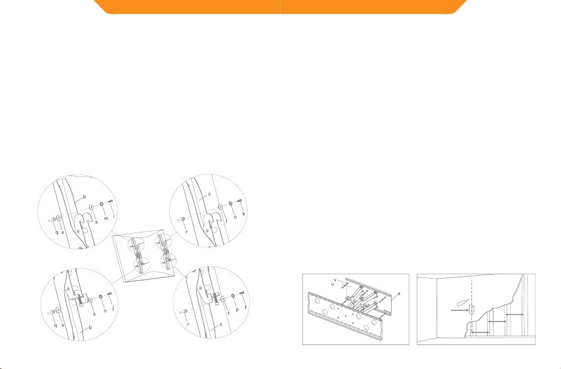
Mounting the monitor
Mounting the wall plate
brackets to a TV with curved
to the wall
Brick, Solid Concrete and Concrete Block mounting:
back
Use the Wall Plate(a) as a template to mark 6 hole locations on the wall.
First of all, make sure the diameter of the Bolt (i,j,k,l) your TV requires.
Three in the top row of slots and three more in the bottom row. Make sure
Once you have determined the correct diameter, please see the relative
these holes are level and there is at least 6”(150mm) distance between
any two holes. Pre-Drill these holes with a 3/8”(10mm) masonry bit to
diagram as below. You will thread the Bolt into the TV using the correct
at least 3”(75mm) in depth. Insert a Concrete Anchor(w) into each of
Lock Washer(m,n,o,p), Washer(s,t) and spacer (q,r). For the M4 or M5
these holes. Make sure the anchor is seated completely ush with the
diameter bolt, you will need another M4/M5 Washer between the
concrete surface even if there is a layer of drywall or other material in
Monitor Bracket and the Spacer. Please make sure the Monitor Brackets
front. Attach the Wall Plate to the wall using 6pcs Lag Bolts(u) and 6pcs
are vertically centered and level with each other.
Lag Bolt Washers(v), shown in Diagram 2A.
Wood Stud mounting:
M4 Diameter Bolt
M6 Diameter Bolt
The Wall Plate(a) must be mounted to two wood studs at least
16”(406mm) apart. Use a stud nder to locate two adjacent studs. It is
a good idea to verify where the studs are located with an awl or thin
nail shown in Diagram 2B. Pre-drill a 3”(75mm) deep hole at the desired
height in each stud using a 5/32”(4mm) drill bit. Make sure these holes
are in the center area of the studs and level with each other. Use the Wall
Diagram 1B
Plate as a template to mark the location of the second hole in each stud.
Drill 3”(75mm) deep holes using the 5/32”(4mm) drill bit in the marked
locations. Attach the Wall Plate to the wall using the 4pcs Lag Bolts(u)
and 4pcs Lag Bolt Washers(v).
M8 Diameter Bolt
M5 Diameter Bolt
Diagram 2A Diagram 2B
16 inch
Stud Finder
16 inch
16 inch
8
9
