Swarovski Optik Z6(i) 5-30x50 P (BT): DE EN EN DE
DE EN EN DE: Swarovski Optik Z6(i) 5-30x50 P (BT)
DE
EN EN
DE
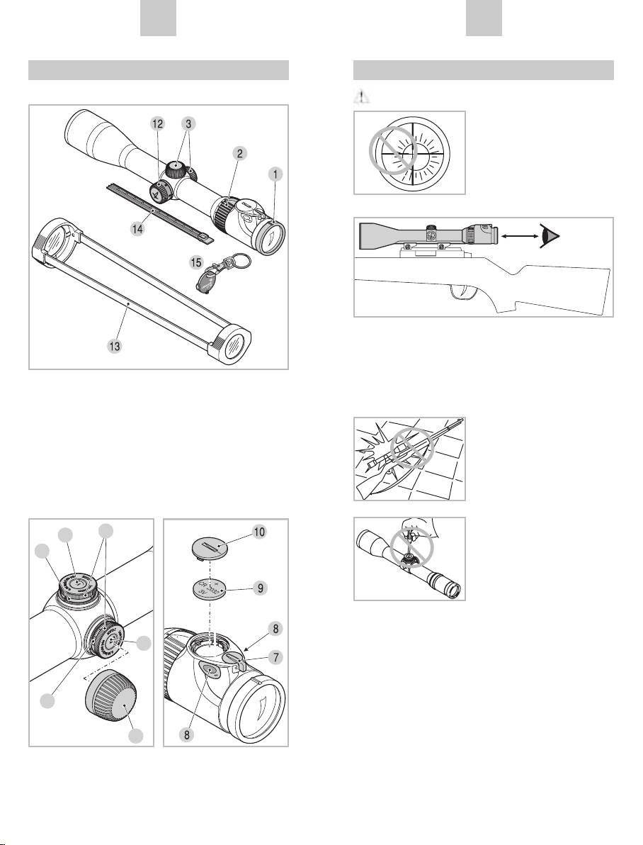
Description
For your safety!
Z6/Z6i
WARNING!
Never use the rifle scope
to look at the sun! This will
lead to damage to your eyes!
Please protect your rifle
scope from unnecessary
solar radiation.
Please note the eye relief distance specified for a
mounted rifle scope (see Data Sheet for dimen-
sions).
General Information
Please protect your rifle
scope against knocks.
Reticle illumination
Repairs should only be
6
4
carried out by authorized
workshops.
4.1
Sealing
5
Thanks to the use of high-quality sealing elements
and controlled fabrication processes, our rifle scopes
are watertight and gas-tight to a pressure of 0.4 bar
5.1
or a depth in water of 4.4 yds/4 m. Seal integrity is
guaranteed even when the screw-on cap has been
removed. Nevertheless, careful handling is advised,
11
especially around the turrets.
16
17
DE
EN EN
DE
The scope has been filled with nitrogen via the sealing
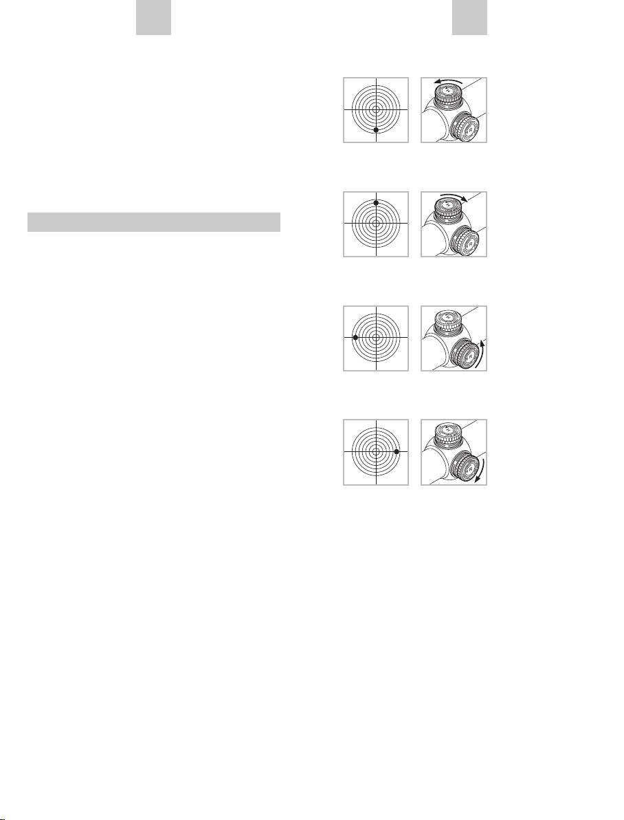
When the shot is low
screw located underneath the windage adjustment
Turn the knurled
turret. Please do not loosen this sealing screw!
knob of the elevation
turret in the direction
of H (counter-clock-
wise).
When the shot is high
Turn the knurled
knob of the elevation
turret in the opposite
Mounting
direction to H (clock-
wise).
Basic Alignment
When the shot is to the left
To ensure perfect alignment of the scope to the
Turn the knurled
rifle, please have a competent gunsmith mount the
knob of the windage
scope.
turret in the direc-
The reticle has been factory-set to the mechanical
tion of R (counter-
middle position. Prior to mounting you can check the
clockwise).
correct position of the reticle. To do this, unscrew the
screw-on caps of the elevation adjustment turret and
windage adjustment turret.
When the shot is to the right
Now turn the respective knurled knob of the eleva-
Turn the knurled
tion adjustment turret and windage adjustment turret
knob of the windage
clockwise until it reaches the stop. Then turn the
turret in the opposite
knurled knob back again counter-clockwise until it
direction to R (clock-
reaches the stop and count the clicks at the same
wise).
time.
Halve the number of clicks and you will have the
exact middle position. Repeat this procedure for the
The impact point correction per click can be taken
second turret.
from the enclosed technical data sheet or the infor-
mation printed on the elevation or windage adjust-
ment turret of your rifle scope.
Alignment of the Scope to the Rifle
If the point of impact of the bullet deviates from the
aiming point, this can be easily and precisely correc-
ted by adjusting the elevation turret and the windage
turret of the scope.
Regardless of corrections, the middle point of the
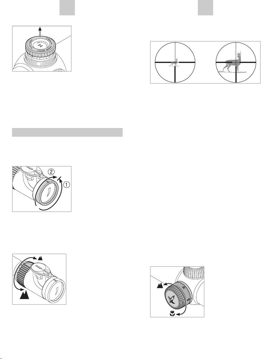
Zero Point Adjustment
aiming mark always stays in the middle of the field
of view.
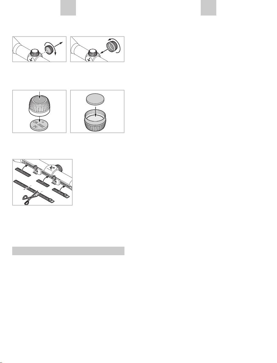
Once you have aligned the scope to the rifle, you can
retain this basic setting. The scale for this is located
To make adjustments, simply unscrew the screw-on
on the respective knurled knob of the elevation/
caps of the elevation and windage turrets.
windage adjustment turret.
18
19
DE
EN EN
DE
nd
1. Pull the knurled
The Reticle in the 2
Image Plane
knob upwards.
(Eyepiece Image Plane)
In this position the
reticle is not adjus-
ted when the knurled
knob is twisted.
2. Turn the knurled knob until the zero point of the
scale is aligned with the index point on the scope.
If the magnification increases, then the reticle
3. Pushing the knurled knob back down re-engages
remains the same size – the size of the image is
the reticle adjustment and the knurled knob. Your
increased but not the size of the reticle. Even for
individual setting is now precisely adjusted as the
large magnifications only a little of the target is cove-
zero point.
red. The reticle can only be used for estimating the
distance to a limited extent.
Operation
Adjusting the Focus
Parallaxe
Simply turn the dioptric correction ring to achieve the
Your rifle scope is set to be parallax-free without
best focus for your individual setting of the reticle.
parallax turret at a target distance of 110 yards
First turn the diop-
(100 m). This means that at a distance of 110 yards
tric correction ring all
(100 m), the image of the object aimed at and the
the way to the left ➀
image of the reticle are in a single plane.
(counter-clockwise)
and then to the right
Please take into consideration:
➁, until the reticle is
With shots at distances greater or less than 110
optimally focused.
yards (100 m), take care to position the eye carefully
central to the scope. This will prevent shifting of the
The adjustment ranges depend on the individual
impact point due to parallax errors.
models. Please consult the technical data sheet
enclosed.
Changing the Magnification
Operation of the Parallax Turret
You can set the desired
(depending on model)
magnification by turning
the (stepless) magni-
Using the parallax turret,
fication adjustment ring
you can adjust the opti-
through 180°. The scale
mum focus for every tar-
on the adjustment ring
get distance thus preven-
allows simple and easy
ting aiming errors due to
reading of the setting.
parallax.
The soft, ribbed covering
of the adjustment ring has a nose for better orien-
tation.
20
21
DE
EN EN
DE
a) Rapid Adjustment
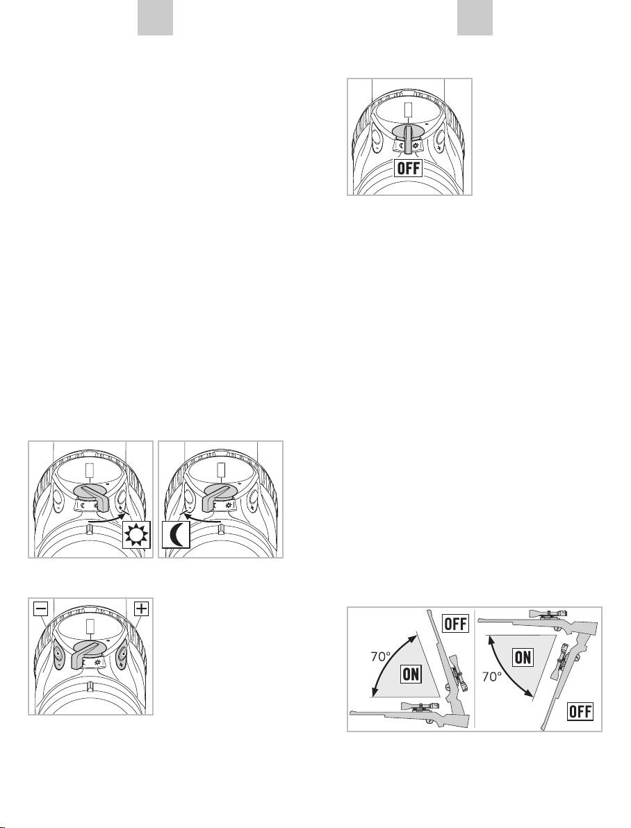
3. Switching off
The target distances are printed on the parallax
To do this, turn the OFF/
turret from 50 m to ∞. Turn the parallax turret until
DAY/NIGHT switch to the
the index point indicates the desired distance. The
center position.
parallax turret also features a detent at 100 m, allo-
wing you to feel when this point has been reached,
especially in twilight.
b) Precision adjustment
Set the magnification as high as possible and turn
the parallax turret until the image appears at its
sharpest. Now move the eye backwards and forwards
within the range of the exit pupil. If in the process
the reticle moves in relation to the image, correct
4. Memory function
the distance setting until it is no longer possible to
When turning off the illumination unit, the last bright-
discern any difference between the movement of the
ness setting used for DAY or NIGHT will be stored
reticle and the movement of the image.
and automatically activated when the unit is turned
on again.
Operation of the Reticle Illumination
5. Automatic turn-off function
1. OFF/DAY/NIGHT switch
The illumination of the unit automatically turns off if
First of all choose between daytime (symbol) and
no brightness adjustment has been carried out within
twilight (symbol) illumination by turning the switch to
a period of 3 hours during the day or 5 hours at night.
the appropriate position.
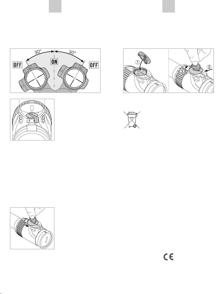
6. SWAROLIGHT
The illuminated Z6 models are equipped with an
intelligent tilt sensor. This senses whether or not the
rifle scope is in a shooting position and transmits this
information to the illumination unit. The rifle scope
switches off if the tilt angle exceeds 70° (upwards or
downwards), if you position the weapon on the turret
2. Brightness control
at a right angle, for example.
You can now adjust the
brightness in the mode
selected by means of the
+/– button. To quickly
find the optimum bright-
ness, the button can
remain pressed (sustai-
ned pulse). You can
make fine adjustments
by pressing the buttons once (individual pulse).
22
23
DE
EN EN
DE
The rifle scope also switches off if the lateral tilt
• When installing the new battery (type CR 2032)
exceeds 30° (if you rest the weapon on your legs,
please make sure that the side marked “+” is
for example).
facing upwards.
When the weapon is returned to the shooting posi-
• Replace the battery cover by matching the two
tion, the illumination automatically switches on.
markings and turning it clockwise a quarter turn.
You can also deactivate
the SWAROLIGHT func-
Batteries Directive
tion by pressing the +/-
Batteries must not be disposed of as
keys at the same time for
household waste and you are legally
5 seconds. The illumina-
obliged to return used batteries. Local
tion point will blink twice
facilities exist for returning used batteries
ON
to confirm the chan-
free of charge (e.g. in retail outlets or at commu-
geover. The SWARO-
nal collection points). Batteries are labelled with a
LIGHT function can be
crossed-out wheeled bin and the chemical symbol
reactivated by repeating this action.
of the harmful substance they contain: “Cd” for cad-
mium, “Hg” for mercury and “Pb” for lead.
Please help us to protect the environment.
7. Battery power indicator
If the illuminated reticle begins to flash, this signi-
Please note!
fies that a battery change will soon be needed. The
The last brightness setting stored will be lost when
remaining operating time will be a few hours, depen-
the battery is changed. When turned on, the illu-
ding on the brightness adjustment and ambient
mination unit will revert to the medium brightness
temperature.
setting in the day range.
8. Changing the battery
9. Battery operating hours
• Turnoffthereticleillu-
mination.
Consult the technical data sheet enclosed!
• Remove the battery
cover with the coin
opener provided tur-
ning it counter clock-
10. Conformity
wise. With a quarter
The reticle illumination unit complies with Directive
turn, the cover lifts off
No. 2004/108/EG regarding electromagnetic com-
its mounting for easy
patibility.
removal.
• Removetheoldbattery.
24
25
DE
EN EN
DE
Attach spare battery container
Cleaning
We have designed all elements and surfaces to
require very little care.
SWAROCLEAN
The SWAROCLEAN non-stick outer surface coating
makes it much easier to clean objective lenses and
eyepiece lenses, especially of any dried-on mineral
deposits (e.g. water marks from condensation),
Battery
insect repellents and tree resin.
To ensure the long-lasting optical brilliance of your
rifle scope, you should keep the glass surfaces free
from dirt, oil and grease. When cleaning the lenses,
first remove larger particles with an optical lens
brush. For subsequent thorough cleaning, breathe
CR 2032
lightly on the lens and clean with the cleaning cloth.
The metal parts are best cleaned with a soft, clean
cloth.
Covering the SWAROVSKI OPTIK Rail
Storage
The cover provided
You should keep your rifle scope in a well-ventilated,
serves to protect the
dry, dark place.
exposed rail parts.
If the rifle scope is wet, it must be dried prior to
It may be cut to the
storage.
required size and
pressed into the rail
by hand.
Maintenance and Care
Lens-Cleaning Cloth
The special microfibre cloth can be used to clean
even the most sensitive glass surfaces. It is suitable
for objective lens, eyepieces and spectacles.
Please keep the microfiber cloth clean as dirt par-
ticles can damage the lens surface. If the cloth is
dirty, it may be washed in lukewarm soapy water and
All details are typical values.
allowed to dry naturally. Please use it exclusively for
We reserve the right to make changes regarding design and delivery.
cleaning lens surfaces.
We accept no liability for printing errors. BA-670-12, 09/2012
26
27
