ASRock b85m: 1.4 Onboard Headers and Connectors
1.4 Onboard Headers and Connectors: ASRock b85m
B85M-DGS
1.4 Onboard Headers and Connectors
Onboard headers and connectors are NOT jumpers. Do NOT place jumper caps over
these headers and connectors. Placing jumper caps over the headers and connectors
will cause permanent damage to the motherboard.
PLED+
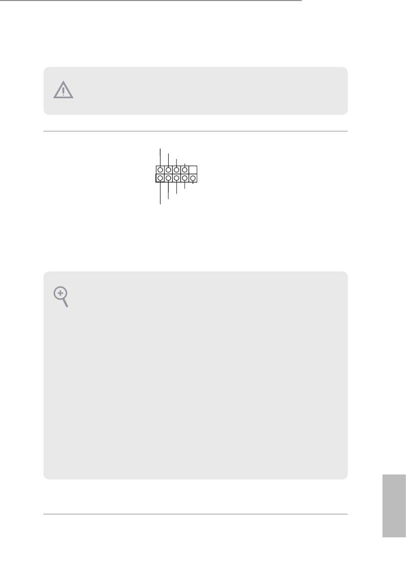
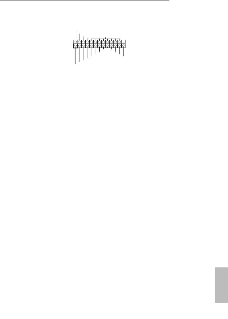
System Panel Header
Connect the power
PLED-
PWRBTN#
(9-pin PANEL1)
GND
switch, reset switch and
(see p.1, No. 12)
system status indicator on
1
GND
the chassis to this header
RESET#
GND
according to the pin
HDLED-
HDLED+
assignments below. Note
the positive and negative
pins before connecting
the cables.
PWRBTN (Power Switch):
Connect to the power switch on the chassis front panel. You may congure the way to
turn o your system using the power switch.
RESET (Reset Switch):
Connect to the reset switch on the chassis front panel. Press the reset switch to restart
the computer if the computer freezes and fails to perform a normal restart.
PLED (System Power LED):
Connect to the power status indicator on the chassis front panel. e LED is on when
the system is operating. e LED keeps blinking when the system is in S1/S3 sleep state.
e LED is o when the system is in S4 sleep state or powered o (S5).
HDLED (Hard Drive Activity LED):
Connect to the hard drive activity LED on the chassis front panel. e LED is on when
the hard drive is reading or writing data.
e front panel design may dier by chassis. A front panel module mainly consists
of power switch, reset switch, power LED, hard drive activity LED, speaker and etc.
When connecting your chassis front panel module to this header, make sure the wire
assignments and the pin assignments are matched correctly.
English
9
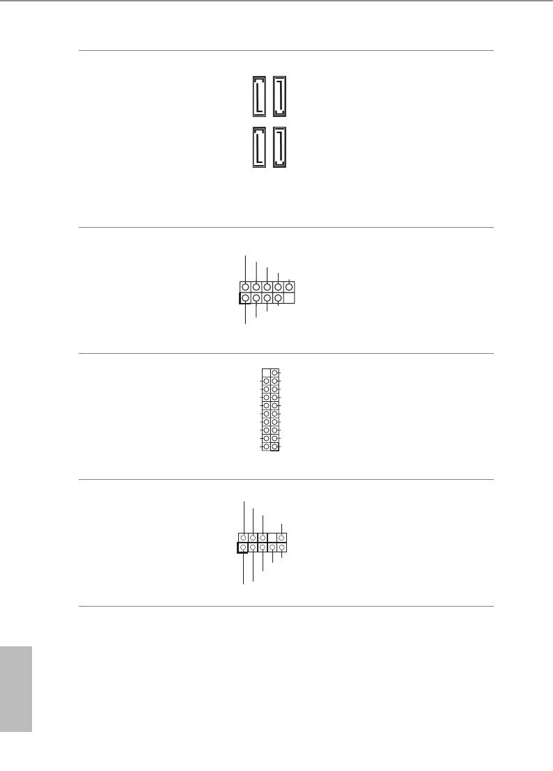
Serial ATA3 Connectors
ese four SATA3
(SATA3_0:
connectors support SATA
see p.1, No. 8)
data cables for internal
SATA3_3
SATA3_2
(SATA3_1:
storage devices with up to
see p.1, No. 9)
6.0 Gb/s data transfer rate.
(SATA3_2:
SATA3_1
SATA3_0
see p.1, No. 7)
(SATA3_3:
see p.1, No. 6)
USB 2.0 Headers
USB_PWR
Besides four USB 2.0 ports
P-
P+
(9-pin USB4_5)
on the I/O panel, there
GND
DUMMY
(see p.1, No. 16)
are two headers on this
(9-pin USB6_7)
1
motherboard. Each USB
GND
(see p.1, No. 14)
P+
2.0 header can support
P-
USB_PWR
two ports.
VbusVbus
USB 3.0 Header
Besides two USB 3.0 ports
Vbus
IntA_ PB_S SRX -
IntA_ PA_S SRX -
IntA_ PB_S SRX +
(19-pin USB3_2_3)
on the I/O panel, there
IntA_ PA_S SRX +
GND
GND
IntA_ PB_S STX -
(see p.1, No. 10)
is one header on this
IntA_ PA_S STX -
IntA_ PB_S STX +
IntA_ PA_S STX +
GND
motherboard. Each USB
GND
IntA_ PB_D -
IntA_ PA_D -
IntA_ PB_D +
3.0 header can support
IntA_ PA_D +
Dummy
1
two ports.
Front Panel Audio Header
GND
is header is for
PRESENCE#
MIC_RET
(9-pin HD_AUDIO1)
OUT_RET
connecting audio devices
(see p.1, No. 21)
to the front audio panel.
1
OUT2_L
J_SENSE
OUT2_R
MIC2_R
MIC2_L
English
10
B85M-DGS
1. High Denition Audio supports Jack Sensing, but the panel wire on the chassis must
support HDA to function correctly. Please follow the instructions in our manual and
chassis manual to install your system.
2. If you use an AC’97 audio panel, please install it to the front panel audio header by
the steps below:
A. Connect Mic_IN (MIC) to MIC2_L.
B. Connect Audio_R (RIN) to OUT2_R and Audio_L (LIN) to OUT2_L.
C. Connect Ground (GND) to Ground (GND).
D. MIC_RET and OUT_RET are for the HD audio panel only. You don’t need to
connect them for the AC’97 audio panel.
E. To activate the front mic, go to the “FrontMic” Tab in the Realtek Control panel
and adjust “Recording Volume”.
Chassis Speaker Header
DUMMY
SPEAKER
Please connect the chassis
1
(4-pin SPEAKER1)
speaker to this header.
+5V
DUMMY
(see p.1, No. 15)
Chassis and Power Fan
Please connect fan cables
Connectors
to the fan connectors and
(4-pin CHA_FAN1)
match the black wire to
(see p.1, No. 17)
the ground pin.
(3-pin PWR_FAN1)
(see p.1, No. 3)
CPU Fan Connector
is motherboard pro-
(4-pin CPU_FAN1)
vides a 4-Pin CPU fan
(see p.1, No. 1)
(Quiet Fan) connector.
If you plan to connect a
3-Pin CPU fan, please
connect it to Pin 1-3.
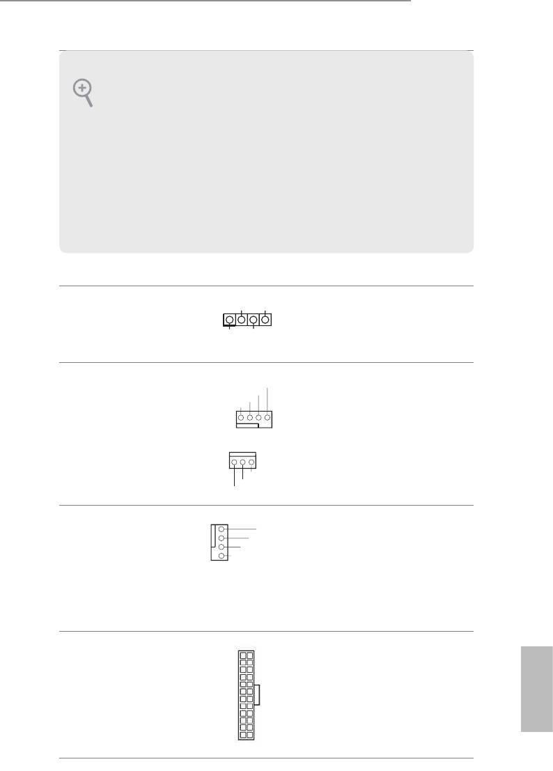
ATX Power Connector
12
24
is motherboard pro-
(24-pin ATXPWR1)
vides a 24-pin ATX power
(see p.1, No. 5)
connector. To use a 20-pin
ATX power supply, please
English
plug it along Pin 1 and Pin
1
13
13.
11
GND
+12V
FAN_SPEED
FAN_SPE ED_CO NTROL
FAN_SPE ED
+12V
GND
1 2 3 4
1
GND
2
+12V
3
FAN_SPE ED
4
FAN_SPE ED_CO NTROL
ATX 12V Power
Please connect an ATX
Connector
12V power supply to this
(4-pin ATX12V1)
connector.
(see p.1, No. 2)
Serial Port Header
RRXD1
is COM1 header
DDTR#1
DDSR#1
(9-pin COM1)
CCTS#1
supports a serial port
(see p.1, No. 19)
module.
1
RRI#1
RRTS#1
GND
TTXD1
DDCD#1
Chassis Intrusion Header
is motherboard
1
(2-pin CI1)
GND
supports CASE OPEN
Signal
(see p.1, No. 20)
detection feature that
detects if the chassis cove
has been removed. is
feature requires a chassis
with chassis intrusion
detection design.
TPM Header
is connector supports
(17-pin TPMS1)
Trusted Platform Module
(see p.1, No. 13)
(TPM) system, which can
GN D
SM B_CLK_MAI N
SM B_DATA_MA IN
LA D2
LA D1
GN D
S_ PWRDWN#
SE RIRQ#
GN D
securely store keys, digital
certicates, passwords,
1
and data. A TPM system
+3 V
LA D3
LA D0
GN D
FR AME
+3 VSB
also helps enhance
PC ICLK
PC IRST#
network security, protects
digital identities, and
ensures platform integrity.
English
12
B85M-DGS
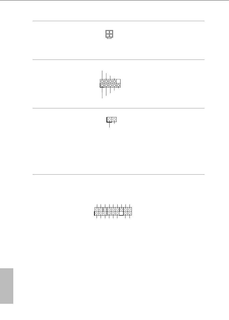
Print Port Header
AF D#
is is an interface
ER ROR#
PI NIT#
(25-pin LPT1)
SL IN#
GN D
for print port cable
(see p.1, No. 18)
that allows convenient
1
SP D7
SP D6
AC K#
connection of printer
SP D5
BU SY
SP D4
PE
SP D3
SL CT
devices.
SP D2
SP D1
SP D0
ST B#
English
13


