ASRock H67M-GE__HT – страница 2
Инструкция к Материнской Плате ASRock H67M-GE__HT

21
ASRock H67M-GE/HT Motherboard
English
For Windows
®
7 / 7 64-bit / Vista
TM
/ Vista
TM
64-bit OS:
Right click the desktop, choose “Personalize”, and select the “Display
Settings” tab so that you can adjust the parameters of the multi-monitor
according to the steps below.
A. Click the number ”2” icon.
B. Click the items “This is my main monitor” and “Extend the desktop onto
this monitor”.
C. Click “OK” to save your change.
D. Repeat steps A through C for the display icon identi
fi
ed by the number
three and four.
6. Use Surround Display. Click and drag the display icons to positions representing
the physical setup of your monitors that you would like to use. The placement
of display icons determines how you move items from one monitor to another.
HDCP Function
HDCP function is supported on this motherboard. To use HDCP
function with this motherboard, you need to adopt the monitor
that supports HDCP function as well. Therefore, you can enjoy
the superior display quality with high-de
fi
nition HDCP
encryption contents. Please refer to below instruction for more
details about HDCP function.
What
is
HDCP?
HDCP stands for High-Bandwidth Digital Content Protection,
a
speci
fi
cation developed by Intel
®
for protecting digital
entertainment content that uses the DVI interface. HDCP is a
copy protection scheme to eliminate the possibility of
intercepting digital data midstream between the video source,
or transmitter - such as a computer, DVD player or set-top box -
and the digital display, or receiver - such as a monitor, television
or projector. In other words, HDCP speci
fi
cation is designed to
protect the integrity of content as it is being transmitted.
Products compatible with the HDCP scheme such as DVD
players, satellite and cable HDTV set-top-boxes, as well as few
entertainment PCs requires a secure connection to a compliant
display. Due to the increase in manufacturers employing HDCP
in their equipment, it is highly recommended that the HDTV or
LCD monitor you purchase is compatible.
22
ASRock H67M-GE/HT Motherboard
English
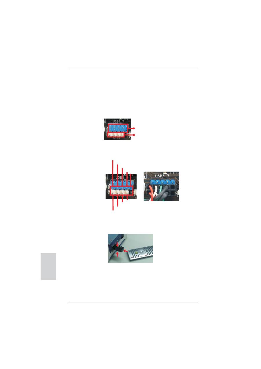
2.6 Remote Receiver Installation Guide
This motherboard is equipped with a 4-pin CIR header (CIR1, see page 2, No. 24),
which is used to connect the Remote Receiver. Please refer to below procedure for
installing the Remote Receiver.
1. Find the CIR header located under the USB 2.0 header (USB6_7, see page 2,
No. 23) on this motherboard.
2. Connect the front USB cable to the USB 2.0 header (as below, pin 1-5) and the
CIR header. Please make sure the wire assignments and the pin assignments are
matched correctly.
3. Install the Remote Receiver to the front USB port. If the Remote Receiver cannot
successfully receive the infrared signals from the Remote Controller, please try to
install it to the other front USB port.
* Only one of the front USB port can support CIR function. When the CIR function is enabled,
the other port will remain USB function.
* The Remote Receiver is used for front USB only. Please do not use the rear USB bracket
to connect it on the rear panel. The Remote Receiver is able to receive the multi-direction
infrared signals (top, down and front), which is compatible with most of the chassis on the
market.
USB 2.0 header (9-pin, blue)
CIR header (4-pin, white)
1 2
4
3
5
USB_PWR
P-
P+
GND
ATX+5VSB
IRRX
IRTX
GND
DUMMY
23
ASRock H67M-GE/HT Motherboard
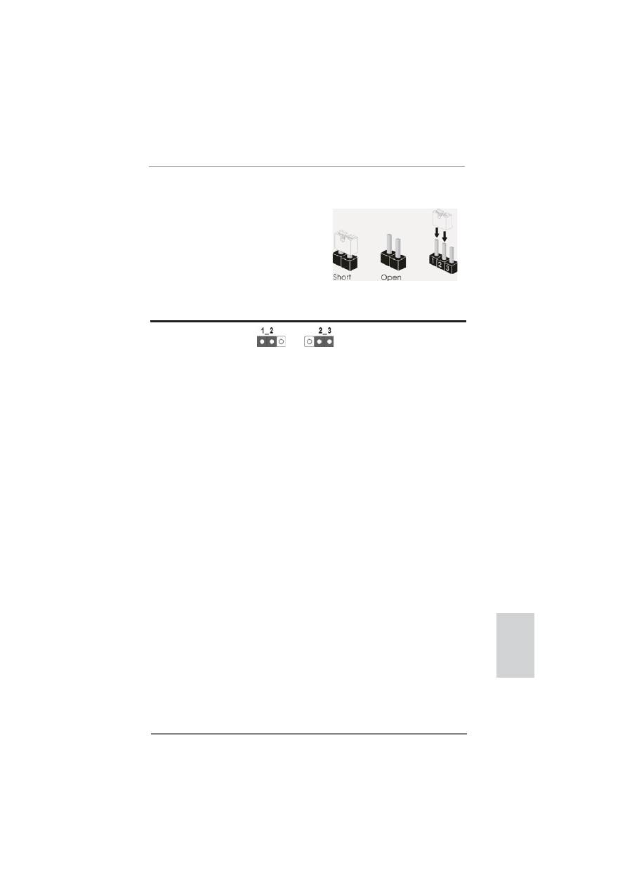
2.7 Jumpers Setup
The illustration shows how jumpers are
setup. When the jumper cap is placed on
pins, the jumper is “Short”. If no jumper cap
is placed on pins, the jumper is “Open”. The
illustration shows a 3-pin jumper whose
pin1 and pin2 are “Short” when jumper cap
is placed on these 2 pins.
Jumper Setting
Description
Clear CMOS Jumper
(CLRCMOS1)
(see p.2, No. 13)
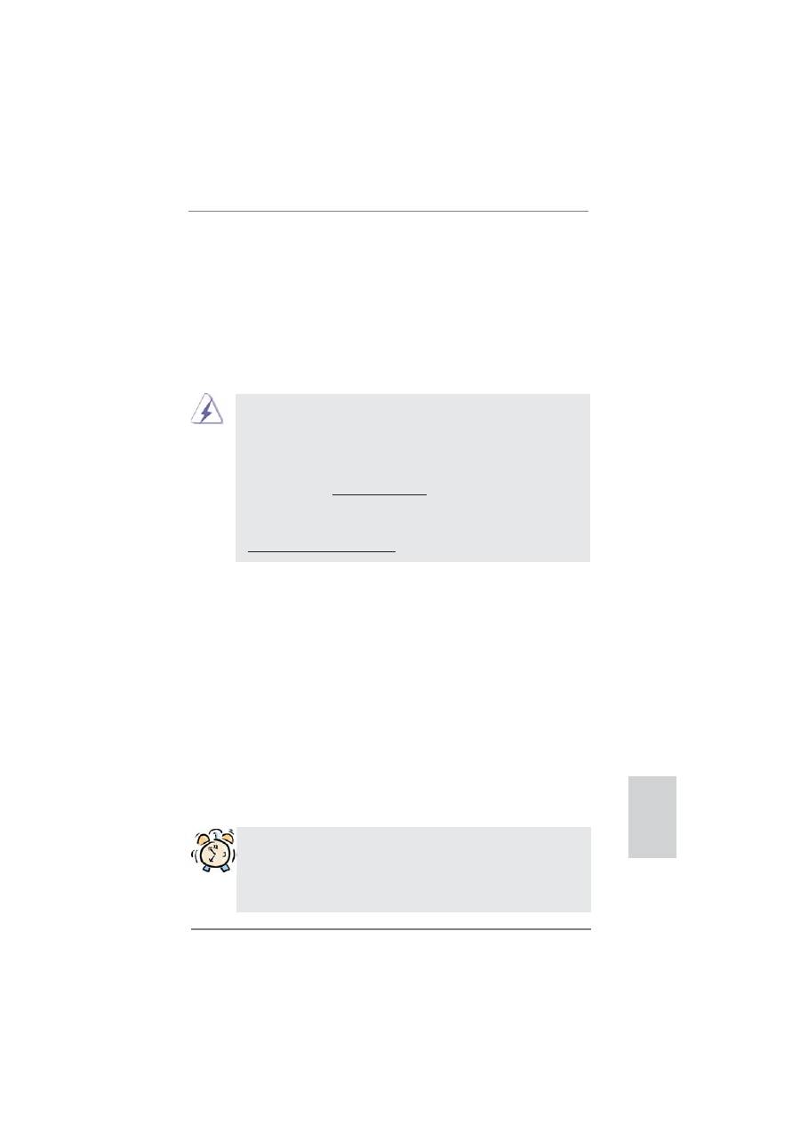
Note: CLRCMOS1 allows you to clear the data in CMOS. To clear and reset the
system parameters to default setup, please turn off the computer and unplug
the power cord from the power supply. After waiting for 15 seconds, use a
jumper cap to short pin2 and pin3 on CLRCMOS1 for 5 seconds. However,
please do not clear the CMOS right after you update the BIOS. If you need
to clear the CMOS when you just
fi
nish updating the BIOS, you must boot
up the system
fi
rst, and then shut it down before you do the clear-CMOS ac-
tion. Please be noted that the password, date, time, user default pro
fi
le, 1394
GUID and MAC address will be cleared only if the CMOS battery is removed.
Clear CMOS
Default
English
24
ASRock H67M-GE/HT Motherboard
English
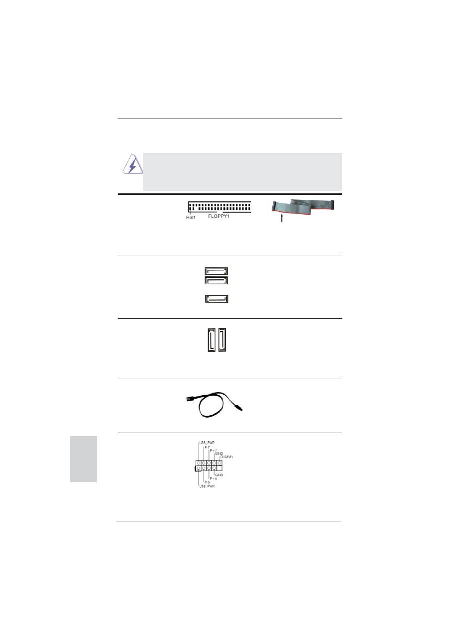
the red-striped side to Pin1
2.8 Onboard Headers and Connectors
Onboard headers and connectors are NOT jumpers. Do NOT place
jumper caps over these headers and connectors. Placing jumper caps
over the headers and connectors will cause permanent damage of the
motherboard!
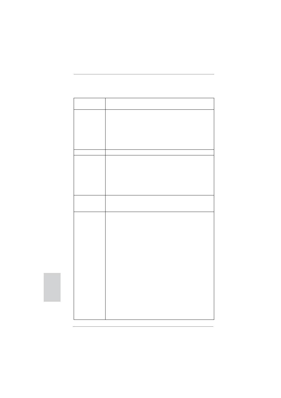
FDD connector
(33-pin FLOPPY1)
(see p.2 No. 27)
Note: Make sure the red-striped side of the cable is plugged into Pin1 side of the
connector.
Serial ATAII Connectors
These three Serial ATAII
(SATA2_2: see p.2, No. 14)
(SATAII) connectors support
(SATA2_3: see p.2, No. 15)
SATA data cables for internal
(SATA2_4: see p.2, No. 16)
storage devices. The current
SATAII interface allows up to
3.0 Gb/s data transfer rate.
Serial ATA3 Connectors
These two Serial ATA3 (SATA3)
(SATA3_0: see p.2, No. 10)
connectors support SATA data
(SATA3_1: see p.2, No. 9)
cables for internal storage
devices. The current SATA3
interface allows up to 6.0 Gb/s
data transfer rate.
Serial ATA (SATA)
Either end of the SATA data
Data Cable
cable can be connected to the
(Optional)
SATA / SATAII / SATA3 hard
disk or the SATAII / SATA3
connector on this motherboard.
SA
TA3_1
SA
TA3_0
SATA2_3
SATA2_2
SATA2_4
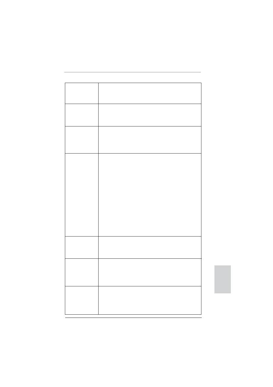
USB 2.0 Headers
Besides four default USB 2.0
(9-pin USB6_7)
ports on the I/O panel, there
(see p.2 No. 23)
are three USB 2.0 headers on
this motherboard. Each
USB 2.0 header can support
two USB 2.0 ports.
25
ASRock H67M-GE/HT Motherboard
English
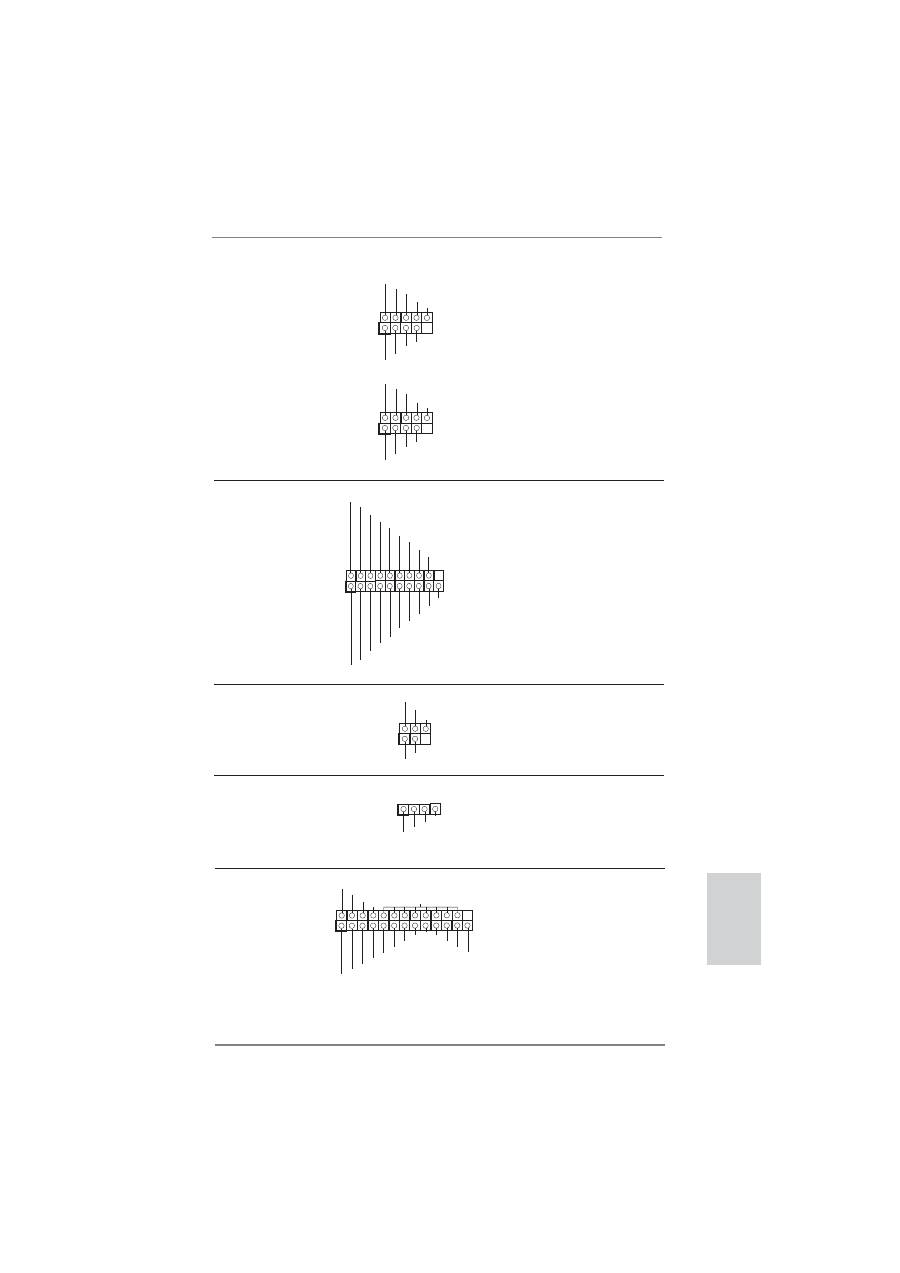
(9-pin USB8_9)
(see p.2 No. 21)
(9-pin USB10_11)
(see p.2 No. 22)
1
USB_PWR
P-8
GND
DUMMY
USB_PWR
P+8
GND
P-9
P+9
1
USB
_
P
W
R
P
-10
G
N
D
DU
MMY
USB
_
P
W
R
P
+10
G
N
D
P
-11
P
+11
Print Port Header
This is an interface for print
(25-pin LPT1)
port cable that allows
(see p.2 No. 26)
convenient connection of printer
devices.
Infrared Module Header
This header supports an
(5-pin IR1)
optional wireless transmitting
(see p.2 No. 25)
and receiving infrared module.
1
IRTX
+5VSB
DUMMY
IRRX
GND
Consumer Infrared Module Header
This header can be used to
(4-pin CIR1)
connect the remote
(see p.2 No. 24)
controller
receiver.
1
ATX+5VSB
IRTX
GND
IRRX
1
AFD#
ERROR#
PINIT#
GND
SLIN#
STB#
SPD0
SPD1
SPD2
SPD3
SPD4
SPD5
SPD6
SPD7
ACK#
BUSY
PE
SLCT
USB 3.0 Header
Besides two default USB 3.0
(19-pin USB_12_13)
ports on the I/O panel, there is
(see p.2 No. 19)
one USB 3.0 header on this
motherboard. This USB 3.0
header can support two USB
3.0
ports.
1
ID
IntA_P1_D+
IntA_P1_D-
GND
IntA_P1_SSTX+
IntA_P1_SSTX-
GND
IntA_P1_SSRX+
IntA_P1_SSRX-
Vbus
IntA_P2_D+
IntA_P2_D-
GND
IntA_P2_SSTX+
IntA_P2_SSTX-
GND
IntA_P2_SSRX+
IntA_P2_SSRX-
Vbus
26
ASRock H67M-GE/HT Motherboard
English
J_SENSE
OUT2_L
1
MIC_RET
PRESENCE#
GND
OUT2_R
MIC2_R
MIC2_L
OUT_RET
Front Panel Audio Header
This is an interface for front
(9-pin HD_AUDIO1)
panel audio cable that allows
(see p.2 No. 29)
convenient connection and
control of audio devices.
1. High De
fi
nition Audio supports Jack Sensing, but the panel wire on
the chassis must support HDA to function correctly. Please follow the
instruction in our manual and chassis manual to install your system.
2. If you use AC’97 audio panel, please install it to the front panel audio
header as below:
A. Connect Mic_IN (MIC) to MIC2_L.
B. Connect Audio_R (RIN) to OUT2_R and Audio_L (LIN) to OUT2_L.
C. Connect Ground (GND) to Ground (GND).
D. MIC_RET and OUT_RET are for HD audio panel only. You don’t
need to connect them for AC’97 audio panel.
E. To activate the front mic.
For Windows
®
XP / XP 64-bit OS:
Select “Mixer”. Select “Recorder”. Then click “FrontMic”.
For Windows
®
7 / 7 64-bit / Vista
TM
/ Vista
TM
64-bit OS:
Go to the "FrontMic" Tab in the Realtek Control panel. Adjust
“Recording Volume”.
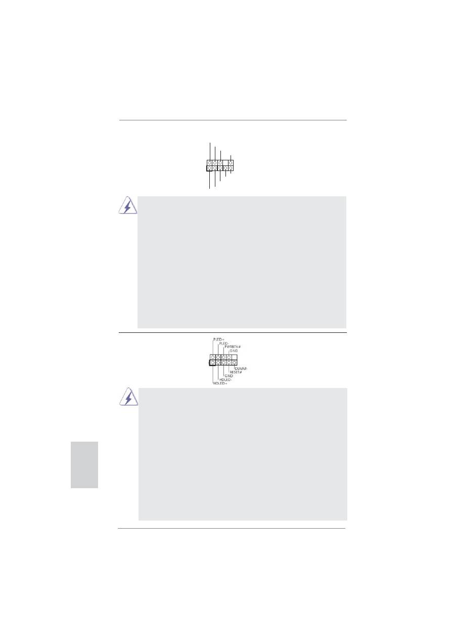
System Panel Header
This header accommodates
(9-pin PANEL1)
several system front panel
(see p.2 No. 17)
functions.
Connect the power switch, reset switch and system status indicator on the
chassis to this header according to the pin assignments below. Note the
positive and negative pins before connecting the cables.
PWRBTN (Power Switch):
Connect to the power switch on the chassis front panel. You may con
fi
gure
the way to turn off your system using the power switch.
RESET (Reset Switch):
Connect to the reset switch on the chassis front panel. Press the reset
switch to restart the computer if the computer freezes and fails to perform a
normal restart.
PLED (System Power LED):
Connect to the power status indicator on the chassis front panel. The LED
is on when the system is operating. The LED keeps blinking when the sys-
tem is in S1 sleep state. The LED is off when the system is in S3/S4 sleep
state or powered off (S5).
27
ASRock H67M-GE/HT Motherboard
English
Chassis Speaker Header
Please connect the chassis
(4-pin SPEAKER 1)
speaker to this header.
(see p.2 No. 18)
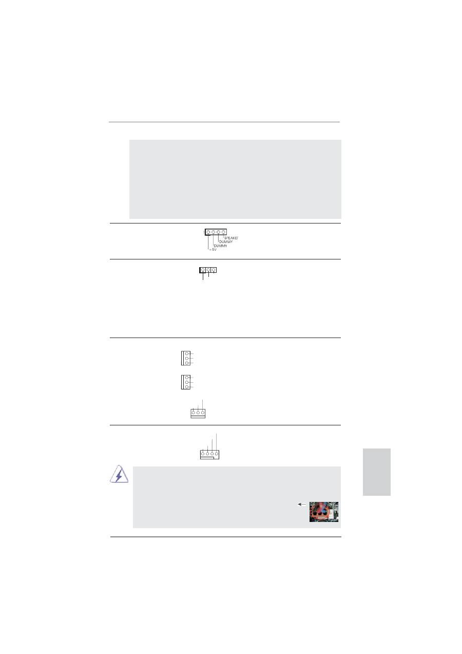
Power LED Header
Please connect the chassis
(3-pin PLED1)
power LED to this header to
(see p.2 No. 20)
indicate system power status.
The LED is on when the system
is operating. The LED keeps
blinking in S1 state. The LED is
off in S3/S4 state or S5 state
(power
off).
1
PLED+
PLED+
PLED-
HDLED (Hard Drive Activity LED):
Connect to the hard drive activity LED on the chassis front panel. The LED
is on when the hard drive is reading or writing data.
The front panel design may differ by chassis. A front panel module mainly
consists of power switch, reset switch, power LED, hard drive activity LED,
speaker and etc. When connecting your chassis front panel module to this
header, make sure the wire assignments and the pin assign-ments are
matched correctly.
Chassis and Power Fan Connectors
Please connect the fan cables
(3-pin CHA_FAN1)
to the fan connectors and
(see p.2 No. 8)
match the black wire to the
ground
pin.
(3-pin CHA_FAN2)
(see p.2 No. 35)
(3-pin PWR_FAN1)
(see p.2 No. 1)
CPU Fan Connectors
Please connect the CPU fan
(4-pin CPU_FAN1)
cable to the connector and
(see p.2 No. 2)
match the black wire to the
ground
pin.
Though this motherboard provides 4-Pin CPU fan (Quiet Fan) support, the 3-Pin
CPU fan still can work successfully even without the fan speed control function.
If you plan to connect the 3-Pin CPU fan to the CPU fan connector on this
motherboard, please connect it to Pin 1-3.
3-Pin Fan Installation
Pin 1-3 Connected
G
N
D
+1
2
V
C
HA_FAN_
SP
EE
D
G
N
D
+1
2
V
C
HA_FAN_
SP
EE
D
GND
+12V
CPU_FAN_SPEED
FAN_SPEED_CONTROL
1 2 3 4
PWR_FAN_SPEED
GND
+12V
28
ASRock H67M-GE/HT Motherboard
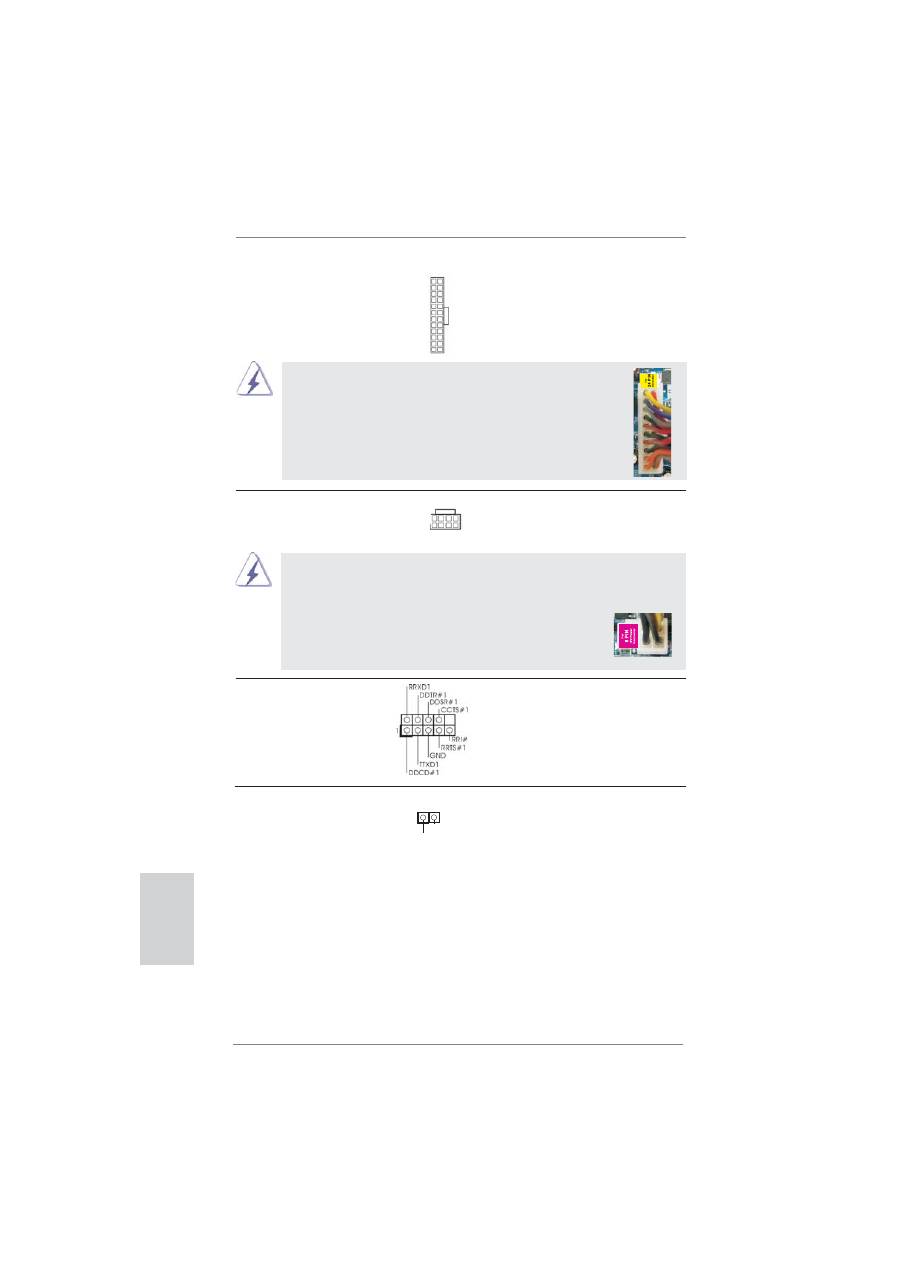
ATX Power Connector
Please connect an ATX power
(24-pin ATXPWR1)
supply to this connector.
(see p.2 No. 7)
12
1
24
13
20-Pin ATX Power Supply Installation
Though this motherboard provides 24-pin ATX power connector,
it can still work if you adopt a traditional 20-pin ATX power supply.
To use the 20-pin ATX power supply, please plug your
power supply along with Pin 1 and Pin 13.
12
1
24
13
ATX 12V Power Connector
Please connect an ATX 12V
(8-pin ATX12V1)
power supply to this connector.
(see p.2 No. 3)
4-Pin ATX 12V Power Supply Installation
Though this motherboard provides 8-pin ATX 12V power connector, it can still work
if you adopt a traditional 4-pin ATX 12V power supply. To use the 4-pin ATX power
supply, please plug your power supply along with Pin 1 and Pin 5.
8 5
4 1
8
5
4
1
HDMI_SPDIF Header
HDMI_SPDIF header, providing
(2-pin HDMI_SPDIF1)
SPDIF audio output to HDMI
(see p.2 No. 30)
VGA card, allows the system to
connect HDMI Digital TV/
projector/LCD devices. Please
connect the HDMI_SPDIF
connector of HDMI VGA card to
this
header.
SPDIFOUT
GND
1
Serial port Header
This COM1 header supports a
(9-pin COM1)
serial port module.
(see p.2 No. 28)
English
29
ASRock H67M-GE/HT Motherboard
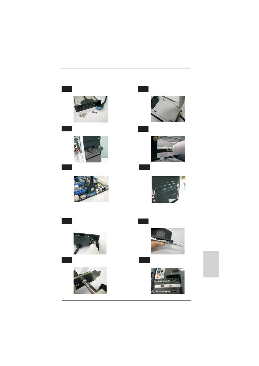
The Installation Guide of Front USB 3.0 Panel
Intall the Front USB 3.0 Panel into the 2.5”
drive bay of the chassis.
Step
3
Step
4
The Front USB 3.0 Panel is ready to use.
Plug the Front USB 3.0 cable into the USB 3.0
header (USB_12_13) on the motherboard.
Step
5
Step
6
Screw the Front USB 3.0 Panel to the
drive bay with six chassis screws.
Prepare the bundled Front USB 3.0 Panel, four
HDD screws, and six chassis screws.
Step
1
Step
2
Screw the 2.5” HDD/SSD to the Front
USB 3.0 Panel with four HDD screws.
The Installation Guide of Rear USB 3.0 Bracket
Put the USB 3.0 cable and the rear
USB 3.0 bracket together.
Unscrew the two screws from the Front USB 3.0
Panel.
Step
1
Step
2
Put the rear USB 3.0 bracket into the
chassis.
Screw the two screws into the rear USB 3.0
bracket.
Step
3
Step
4
English

30
ASRock H67M-GE/HT Motherboard
2.9 Driver Installation Guide
To install the drivers to your system, please insert the support CD to your optical
drive
fi
rst. Then, the drivers compatible to your system can be auto-detected and
listed on the support CD driver page. Please follow the order from up to bottom side
to install those required drivers. Therefore, the drivers you install can work properly.
2.10 Installing
Windows
®
7 / 7 64-bit / Vista
TM
/ Vista
TM
64-bit / XP / XP 64-bit With RAID Functions
If you want to install Windows
®
7 / 7 64-bit / Vista
TM
/ Vista
TM
64-bit / XP / XP 64-
bit on your SATA / SATAII / SATA3 HDDs with RAID functions, please refer to the
document at the following path in the Support CD for detailed procedures:
..\ RAID Installation Guide
2.11 Installing
Windows
®
7 / 7 64-bit / Vista
TM
/ Vista
TM
64-bit / XP
/ XP 64-bit Without RAID Functions
If you want to install Windows
®
7 / 7 64-bit / Vista
TM
/ Vista
TM
64-bit / XP / XP 64-
bit OS on your SATA / SATAII / SATA3 HDDs without RAID functions, please follow
below procedures according to the OS you install.
2.11.1 Installing Windows
®
XP / XP 64-bit Without RAID
Functions
If you want to install Windows
®
XP / XP 64-bit OS on your SATA / SATAII / SATA3
HDDs without RAID functions, please follow below steps.
STEP 1: Set up BIOS.
A. Enter BIOS SETUP UTILITY Advanced screen SATA Con
fi
guration.
B. Set the option “SATA Mode” to [IDE].
STEP 2: Install Windows
®
XP / XP 64-bit OS on your system.
Using SATA / SATAII / SATA3 HDDs without NCQ function
English
31
ASRock H67M-GE/HT Motherboard
English
2.11.2 Installing Windows
®
7 / 7 64-bit / Vista
TM
/ Vista
TM
64-bit
Without RAID Functions
If you want to install Windows
®
7 / 7 64-bit / Vista
TM
/ Vista
TM
64-bit OS on your SATA
/ SATAII / SATA3 HDDs without RAID functions, please follow below steps.
Using SATA / SATAII / SATA3 HDDs with NCQ function
STEP 1: Set Up BIOS.
A. Enter BIOS SETUP UTILITY Advanced screen SATA Con
fi
guration.
B. Set the option “SATA Mode” to [AHCI].
STEP 2: Install Windows
®
7 / 7 64-bit / Vista
TM
/ Vista
TM
64-bit OS on your
system.
Using SATA / SATAII / SATA3 HDDs without NCQ function
STEP 1: Set up BIOS.
A. Enter BIOS SETUP UTILITY Advanced screen SATA Con
fi
guration.
B. Set the option “SATA Mode” to [IDE].
STEP 2: Install Windows
®
7 / 7 64-bit / Vista
TM
/ Vista
TM
64-bit OS on your
system.

32
ASRock H67M-GE/HT Motherboard
English
3. BIOS Information
The Flash Memory on the motherboard stores BIOS Setup Utility. When you start up
the computer, please press <F2> or <Del> during the Power-On-Self-Test (POST)
to enter BIOS Setup utility; otherwise, POST continues with its test routines. If you
wish to enter BIOS Setup after POST, please restart the system by pressing <Ctl>
+ <Alt> + <Delete>, or pressing the reset button on the system chassis. The BIOS
Setup program is designed to be user-friendly. It is a menu-driven program, which
allows you to scroll through its various sub-menus and to select among the prede-
termined choices. For the detailed information about BIOS Setup, please refer to the
User Manual (PDF
fi
le) contained in the Support CD.
4. Software Support CD information
This motherboard supports various Microsoft
®
Windows
®
operating systems: 7 / 7
64-bit / Vista
TM
/ Vista
TM
64-bit / XP / XP 64-bit. The Support CD that came with the
motherboard contains necessary drivers and useful utilities that will enhance moth-
erboard features. To begin using the Support CD, insert the CD into your CD-ROM
drive. It will display the Main Menu automatically if “AUTORUN” is enabled in your
computer. If the Main Menu does not appear automatically, locate and double-click
on the
fi
le “ASSETUP.EXE” from the BIN folder in the Support CD to display the
menus.
33
ASRock H67M-GE/HT Motherboard
Deutsch
1. Einführung
Wir danken Ihnen für den Kauf des ASRock
H67M-GE/HT
Motherboard, ein zuver-
lässiges Produkt, welches unter den ständigen, strengen Qualitätskontrollen von
ASRock gefertigt wurde. Es bietet Ihnen exzellente Leistung und robustes Design,
gemäß der Verpflichtung von ASRock zu Qualität und Halbarkeit. Diese Schnel-
linstallationsanleitung führt in das Motherboard und die schrittweise Installation
ein. Details über das Motherboard
fi
nden Sie in der Bedienungsanleitung auf der
Support-CD.
Da sich Motherboard-Spezi
fi
kationen und BIOS-Software verändern
können, kann der Inhalt dieses Handbuches ebenfalls jederzeit geändert
werden. Für den Fall, dass sich Änderungen an diesem Handbuch
ergeben, wird eine neue Version auf der ASRock-Website, ohne weitere
Ankündigung, verfügbar sein. Die neuesten Gra
fi
kkarten und unterstützten
CPUs sind auch auf der ASRock-Website aufgelistet.
ASRock-Website: http://www.asrock.com
Wenn Sie technische Unterstützung zu Ihrem Motherboard oder spezi
fi
sche
Informationen zu Ihrem Modell benötigen, besuchen Sie bitte unsere
Webseite:
www.asrock.com/support/index.asp
1.1 Kartoninhalt
ASRock
H67M-GE/HT
Motherboard
(Micro ATX-Formfaktor: 24.4 cm x 24.4 cm; 9.6 Zoll x 9.6 Zoll)
ASRock
H67M-GE/HT
Schnellinstallationsanleitung
ASRock
H67M-GE/HT
Support-CD
Zwei Serial ATA (SATA) -Datenkabel (optional)
Ein I/O Shield
Ein USB 3.0-Frontblende
Vier Festplatte Schrauben
Sechs Gehäuses Schrauben
Ein USB 3.0-Blech an der Rückwand
Ein 3D-Rot-Grün-Anaglyphenbrille (optional)
Ein Remote-Empfänger (optional)
Ein Fernbedienung (optional)
ASRock erinnert...
Zur besseren Leistung unter Windows
®
7 / 7, 64 Bit / Vista
TM
/ Vista
TM
64 Bit empfehlen wir, die Speicherkon
fi
guration im BIOS auf den AHCI-
Modus einzustellen. Hinweise zu den BIOS-Einstellungen
fi
nden Sie in
der Bedienungsanleitung auf der mitgelieferten CD.
34
ASRock H67M-GE/HT Motherboard
1.2 Spezifikationen
Plattform
- Micro ATX-Formfaktor: 24.4 cm x 24.4 cm; 9.6 Zoll x 9.6 Zoll
- Alle Feste Kondensatordesign
CPU
- Unterstützt Intel
®
Core
TM
(2te Generation) i7 / i5 / i3 im
LGA1155-Paket
- 4 + 1-Stromphasendesign
- Unterstützt Intel
®
Turbo Boost 2.0-Technologie
- Unterstützt freigegebene CPU der K-Serie
- Unterstützt Hyper-Threading-Technologie
(siehe
VORSICHT 1
)
Chipsatz
- Intel
®
H67
Speicher
- Unterstützung von Dual-Kanal-Speichertechnologie
(siehe
VORSICHT 2
)
- 4 x Steckplätze für DDR3
- Unterstützt DDR3 1333/1066 non-ECC, ungepufferter
Speicher
- Max. Kapazität des Systemspeichers: 32GB
(siehe
VORSICHT 3
)
Erweiterungs-
- 1 x PCI Express 2.0 x16-Steckplatz (blau für x16-Modus)
steckplätze
- 2 x PCI Express 2.0 x1-Steckplätze
- 1 x PCI -Steckplätze
Onboard-VGA *
* Benötigt einen Prozessor mit Intel
®
-Gra
fi
ktechnologie
-
Intel
®
HD Gra
fi
k 2000/3000
- Pixel Shader 4.1, DirectX 10.1
- Maximal gemeinsam genutzter Speicher 1759MB
(siehe
VORSICHT 4
)
- Vier VGA-Ausgangsoptionen: D-Sub, DVI-D, HDMI sowie
DisplayPort (siehe
VORSICHT 5
)
- Unterstützt HDMI 1.4a mit einer maximalen Au
fl
ösung von
1920 x 1200 bei 60 Hz
- Unterstützt DVI mit einer maximalen Au
fl
ösung von
1920 x 1200 bei 60 Hz
- Unterstützt D-Sub mit einer maximalen Au
fl
ösung von
2048 x 1536 bei 75 Hz
- Unterstützt DisplayPort mit einer maximalen Au
fl
ösung von
2560 x 1600 bei 60 Hz
- Unterstützt Auto Lip Sync, Deep Color (12bpc), xvYCC und
HBR (High Bit Rate-Audio) mit HDMI (kompatibler HDMI-
Bildschirm erforderlich) (siehe
VORSICHT 6
)
- Unterstützt stereoskopisches 3D per Blu-ray mit HDMI 1.4a
Deutsch
35
ASRock H67M-GE/HT Motherboard
Deutsch
- Unterstützt HDCP-Funktion mit DVI- , HDMI- und Display
Port-Ports
- Unterstutzt 1080p Blu-ray (BD) / HD-DVD-Wiedergabe mit
DVI- , HDMI- und Display Port-Ports
Audio
-
7.1
CH HD Audio mit dem Inhalt Schutz
(Realtek ALC892 Audio Codec)
- Premium Blu-ray-Audio-Unterstützung
- Unterstützt THX TruStudio Pro
TM
LAN
- PCIE x1 Gigabit LAN 10/100/1000 Mb/s
- Realtek RTL8111E
- Unterstützt Wake-On-LAN
- Unterstützt LAN-Kabelerkennung
- Unterstützt energieef
fi
zientes Ethernet 802.3az
E/A-Anschlüsse
I/O Panel
an der
- 1 x PS/2-Tastaturanschluss
Rückseite
- 1 x VGA/D-Sub port
- 1 x VGA/DVI-D port
- 1 x HDMI port
- 1 x DisplayPort
- 1 x optischer SPDIF-Ausgang
- 4 x Standard-USB 2.0-Anschlüsse
- 1 x eSATA2-Anschluss
- 2 x Standard-USB 3.0-Anschlüsse
- 1 x RJ-45 LAN Port mit LED (ACT/LINK LED und SPEED
LED)
- HD Audiobuchse: Lautsprecher hinten / Mitte/Bass /
Audioeingang / Lautsprecher vorne / Mikrofon
(siehe
VORSICHT 7
)
SATA3
- 2 x SATA 3-Anschlüsse (6,0 Gb/s); unterstützt RAID-
(RAID 0, RAID 1, RAID 10, RAID 5 und Intel Rapid
Storage), NCQ-, AHCI-und „Hot Plug“ (Hot-Plugging)-
Funktionen
USB3.0
- 2 x USB 3.0-Ports an der Rückseite durch Etron EJ168A,
unterstützt USB 1.0/2.0/3.0 mit bis zu 5 Gb/s
- 1 x USB 3.0-Header (unterstützt zwei USB 3.0-Ports) an der
Vorderseite durch Etron EJ168A, unterstützt USB 1.0/2.0/
3.0 mit bis zu 5 Gb/s
Anschlüsse
- 3 x SATA2 3,0 GB/s-Anschlüsse, unterstützen RAID-
(RAID 0, RAID 1, RAID 10, RAID 5 und Intel Rapid
Storage), NCQ-, AHCI-und „Hot Plug“ (Hot-Plugging)-
Funktionen
- 2 x SATA3 6,0 GB/s-Anschlüsse
36
ASRock H67M-GE/HT Motherboard
- 1 x FDD-Anschlüsse
- 1 x Infrarot-Modul-Header
- 1 x Consumer Infrared-Modul-Header
- 1 x Druckerport-Anschlussleiste
- 1 x COM-Anschluss-Header
- 1 x HDMI_SPDIF-Anschluss
- 1 x Betriebs-LED-Header
-
CPU/Gehäuse/Stromlüfter-Anschluss
-
24-pin
ATX-Netz-Header
- 8-pin anschluss für 12V-ATX-Netzteil
- Anschluss für Audio auf der Gehäusevorderseite
- 3 x USB 2.0-Anschlüsse (Unterstützung 6 zusätzlicher
USB 2.0-Anschlüsse)
- 1 x USB 3.0-Anschlüsse (Unterstützung 2 zusätzlicher
USB 3.0-Anschlüsse)
BIOS
- 64Mb AMI BIOS
- AMIs Legal BIOS UEFI mit GUI-Unterstützung
- Unterstützung für “Plug and Play”
-
ACPI
1.1-Weckfunktionen
-
JumperFree-Übertaktungstechnologie
- SMBIOS 2.3.1
- IGPU, DRAM, PCH, CPU PLL, VTT, VCSA Stromspannung
Multianpassung
Support-CD
- Treiber, Dienstprogramme, Anti-Virus-Software
(Testversion), ASRock Software Suite (CyberLink DVD
Suite) (OEM- und Testversion)
Einzigartige
- ASRock Extreme Tuning Utility (AXTU) (siehe
VORSICHT 8
)
Eigenschaft
-
Sofortstart
- ASRock Instant Flash (siehe
VORSICHT 9
)
- ASRock AIWI (siehe
VORSICHT 10
)
- ASRock APP Charger (siehe
VORSICHT 11
)
- SmartView (siehe
VORSICHT 12
)
- Hybrid Booster:
- ASRock U-COP (siehe
VORSICHT 13
)
- Boot Failure Guard (B.F.G. – Systemstartfehlerschutz)
- Combo-Kühleroption (siehe
VORSICHT 14
)
- Gute Nacht-LED
Hardware Monitor
- Überwachung der CPU-Temperatur
-
Motherboardtemperaturerkennung
- Drehzahlmessung für CPU/Gehäuse/Stromlüfter
- Geräuscharmer CPU-/Gehäuselüfter (ermöglicht die au
tomatische Anpassung der Gehäuselüftergeschwindigkeit
durch CPU- oder MB-Temperatur)
Deutsch
37
ASRock H67M-GE/HT Motherboard
Deutsch
VORSICHT!
1. Die Einstellung der “Hyper-Threading Technology”,
fi
nden Sie auf Seite
50 des auf der Support-CD enthaltenen Benutzerhandbuches beschrie-
ben.
2. Dieses Motherboard unterstützt Dual-Kanal-Speichertechnologie. Vor
Implementierung der Dual-Kanal-Speichertechnologie müssen Sie die
Installationsanleitung für die Speichermodule auf Seite 44 zwecks
richtiger Installation gelesen haben.
3. Durch Betriebssystem-Einschränkungen kann die tatsächliche Speicher-
größe weniger als 4 GB betragen, da unter Windows
®
7 / Vista™ / XP
etwas Speicher zur Nutzung durch das System reserviert wird. Unter
Windows
®
OS mit 64-Bit-CPU besteht diese Einschränkung nicht.
4. Die Maximalspeichergröße ist von den Chipshändler de
fi
niert und umge-
tauscht. Bitte überprüfen Sie Intel
®
website für die neuliche Information.
5. Sie können nur die Nutzung von zwei von vier Bildschirmen auswählen.
Die D-Sub-, DVI-D-, HDMI- und DisplayPort-Bildschirme können nicht
gleichzeitig aktiviert werden. Zudem kann der DVI-D-Port mit DVI-zu-
HDMI-Adapter dieselben Funktionen wie der HDMI-Port unterstützen.
6. xvYCC und Deep Color werden nur unter Windows
®
7 64-Bit / 7 unter-
stützt. Der Deep Color-Modus wird nur aktiviert, wenn der Bildschirm
12bpc in EDID unterstützt. HBR wird unter Windows
®
7 64 Bit / 7 / Vista
TM
64 Bit / Vista
TM
unterstützt.
7. Der Mikrofoneingang dieses Motherboards unterstützt Stereo- und Mono-
Modi. Der Audioausgang dieses Motherboards unterstützt 2-Kanal-,
4-Kanal-, 6-Kanal- und 8-Kanal-Modi. Stellen Sie die richtige Verbindung
anhand der Tabelle auf Seite 3 her.
WARNUNG
Beachten Sie bitte, dass Overclocking, einschließlich der Einstellung im BIOS,
Anwenden der Untied Overclocking-Technologie oder Verwenden von Overclocking-
Werkzeugen von Dritten, mit einem gewissen Risiko behaftet ist. Overclocking kann
sich nachteilig auf die Stabilität Ihres Systems auswirken oder sogar Komponenten
und Geräte Ihres Systems beschädigen. Es geschieht dann auf eigene Gefahr und
auf Ihre Kosten. Wir übernehmen keine Verantwortung für mögliche Schäden, die
aufgrund von Overclocking verursacht wurden.
-
Mehrstu
fi
ge Geschwindigkeitsteuerung für CPUlüfter
- Spannungsüberwachung: +12V, +5V, +3.3V, Vcore
Betriebssysteme
- Unterstützt Microsoft
®
Windows
®
7 / 7 64-Bit / Vista
TM
/
Vista
TM
64-Bit / XP / XP 64-Bit
Zerti
fi
zierungen
- FCC, CE, WHQL
- Gemäß Ökodesign-Richtlinie (ErP/EuP) (Stromversorgung
gemäß Ökodesign-Richtlinie (ErP/EuP) erforderlich)
(siehe
VORSICHT 15
)
* Für die ausführliche Produktinformation, besuchen Sie bitte unsere Website:
http://www.asrock.com

38
ASRock H67M-GE/HT Motherboard
8. ASRock Extreme Tuning Utility (AXTU) ist ein Alles-in-einem-
Werkzeug zur Feineinstellung verschiedener Systemfunktionen an
einer benutzerfreundlichen Schnittstelle; diese beinhaltet Hardware-
Überwachung, Lüftersteuerung, Übertaktung, OC DNA und IES. Über die
Hardware-Überwachung können Sie die Hauptsystemdaten einsehen.
Die Lüftersteuerung zeigt Ihnen zur Anpassung Lüftergeschwindigkeit
und Temperatur an. Bei der Übertaktung können Sie die CPU-Frequenz
zur Erzielung optimaler Systemleistung übertakten. OC DNA ermöglicht
Ihnen die Speicherung Ihrer OC-Einstellungen als Pro
fi
l, welches Sie
mit Freunden teilen können. Ihre Freunde können das OC-Pro
fi
l dann
in ihrem System laden und so die gleichen OC-Einstellungen erzielen.
Per IES (Intelligent Energy Saver) kann der Spannungsregulator bei
Inaktivität der CPU-Kerne die Anzahl an Ausgangsphasen zur Steigerung
der
Ef
fi
zienz reduzieren – ohne die Rechenleistung zu beeinträchtigen.
Hinweise zur Bedienung der ASRock Extreme Tuning Utility (AXTU)
fi
nden Sie auf unserer Webseite.
ASRock-Webseite: http://www.asrock.com
9. ASRock Instant Flash ist ein im Flash-ROM eingebettetes BIOS-Flash-
Programm. Mithilfe dieses praktischen BIOS-Aktualisierungswerkzeugs
können Sie das System-BIOS aktualisieren, ohne dafür zuerst Betriebs-
systeme wie MS-DOS oder Windows
®
aufrufen zu müssen. Mit diesem
Programm bekommen Sie durch Drücken der <F6>-Taste
während des POST-Vorgangs oder durch Drücken der <F2>-Taste im
BIOS-Setup-Menü Zugang zu ASRock Instant Flash. Sie brauchen dieses
Werkzeug einfach nur zu starten und die neue BIOS-Datei auf Ihrem
USB-Flash-Laufwerk, Diskettenlaufwerk oder der Festplatte zu speichern,
und schon können Sie Ihr BIOS mit nur wenigen Klickvorgängen ohne
Bereitstellung einer zusätzlichen Diskette oder eines anderen kompli-
zierten Flash-Programms aktualisieren. Achten Sie darauf, dass das
USB-Flash-Laufwerk oder die Festplatte das Dateisystem FAT32/16/12
benutzen muss.
10. Das Erlebnis intuitiver, bewegungsgesteuerter Spiele ist nicht mehr
nur noch an der Wii möglich. Das ASRock AIWI-Dienstprogramm führt
eine neue Möglichkeit der PC-Spielsteuerung ein. ASRock AIWI ist das
weltweit erste Dienstprogramm, mit dem Sie Ihr iPhone/iPod touch in
einen Joystick zur Steuerung Ihrer PC-Spiele verwandeln können. Sie
müssen lediglich das ASRock AIWI-Dienstprogramm – entweder von der
of
fi
ziellen ASRock-Webseite oder der ASRock-Software-CD Ihres Moth-
erboards – installieren sowie das kostenlose AIWI Lite vom App Store
auf Ihr iPhone/iPod touch herunterladen. Verbinden Sie Ihren PC und
das Apple-Gerät via Bluetooth oder Wi-Fi-Netzwerk – schon können Sie
die bewegungsgesteuerten Spiele genießen. Bitte denken Sie außerdem
daran, regelmäßig einen Blick auf die of
fi
zielle ASRock-Webseite zu
werfen; wir bieten stets topaktuelle Informationen über die unterstützten
Spiele!
ASRock-Webseite:
http://www.asrock.com/Feature/Aiwi/index.asp
Deutsch
39
ASRock H67M-GE/HT Motherboard
Deutsch
11. Wenn Sie nach einer schnelleren, weniger eingeschränkten Möglich-
keit zur Au
fl
adung Ihrer Apple-Geräte (z. B. iPhone/iPad/iPod touch)
suchen, bietet ASRock Ihnen eine wunderbare Lösung – den ASRock
APP Charger. Installieren Sie einfach den ASRock APP Charger-Treiber;
dadurch lädt sich Ihr iPhone wesentlich schneller über einen Computer-
auf – genaugenommen bis zu 40 % schneller als zuvor. Der ASRock APP
Charger ermöglicht Ihnen die schnelle Au
fl
adung mehrerer Apple-Geräte
gleichzeitig; der Ladevorgang wird sogar dann fortgesetzt, wenn der PC
den Ruhezustand (S1), Suspend to RAM-Modus (S3) oder Tiefschlafmo-
dus (S4) aufruft oder ausgeschaltet wird (S5). Nach der Installation des
APP Charger-Treibers können Sie im Handumdrehen das großartigste
Ladeerlebnis überhaupt genießen. ASRock-Webseite: http://www.asrock.
com/Feature/AppCharger/index.asp
12. SmartView, eine neue Internetbrowserfunktion, ist eine intelligente IE-
Startseite, die meist besuchte Internetseiten, Ihren Browserverlauf,
Facebook-Freunde und Nachrichten in Echtzeit miteinander kombiniert:
In einer speziellen Ansicht, die das Internet noch angenehmer und aufre-
gender macht. ASRock-Motherboards werden exklusiv mit der Smart-
View-Software geliefert, die auch dafür sorgt, dass Sie immer mit Ihren
Freunden in Verbindung bleiben. Die SmartView-Funktionen können Sie
mit den Windows
®
-Betriebssystemen 7 / 7, 64 Bit / Vista
TM
/ Vista
TM
64 Bit
und dem Internet Explorer ab Version 8 nutzen. ASRock-Website: http://
www.asrock.com/Feature/SmartView/index.asp
13. Wird eine Überhitzung der CPU registriert, führt das System einen au-
tomatischen Shutdown durch. Bevor Sie das System neu starten,
prüfen Sie bitte, ob der CPU-Lüfter am Motherboard richtig funktioniert,
und stecken Sie bitte den Stromkabelstecker aus und dann wieder ein.
Um die Wärmeableitung zu verbessern, bitte nicht vergessen, etwas
Wärmeleitpaste zwischen CPU und Kühlkörper zu sprühen.
14. Die Combo-Kühleroption bietet die
fl
exible Möglichkeit zur Aufnahme von
drei verschiedenen CPU-Kühlertypen, Socket LGA 775, LGA 1155 und LGA
1156. Beachten Sie bitte, dass nicht alle 775 und 1156 CPU-Lüfter verwen-
det werden können.
15. EuP steht für Energy Using Product und kennzeichnet die Ökodesign-Richt-
linie, die von der Europäischen Gemeinschaft zur Festlegung des Ener-
gieverbrauchs von vollständigen Systemen in Kraft gesetzt wurde. Gemäß
dieser Ökodesign-Richtlinie (EuP) muss der gesamte Netzstromverbrauch
von vollständigen Systemen unter 1,00 Watt liegen,
wenn sie ausgeschaltet sind. Um dem EuP-Standard zu entsprechen,
sind ein EuP-fähiges Motherboard und eine EuP-fähige Stromversorgung
erforderlich. Gemäß einer Empfehlung von Intel muss eine EuP-fähige
Stromversorgung dem Standard entsprechen, was bedeutet, dass bei
einem Stromverbrauch von 100 mA die 5-Volt-Standby-Energieef
fi
zienz
höher als 50% sein sollte. Für die Wahl einer EuP-fähigen Stromversorgung
empfehlen wir Ihnen, weitere Details beim Hersteller der Stromversorgung
abzufragen.
40
ASRock H67M-GE/HT Motherboard
Contact Array
Socket Body
Load Lever
Load Plate
2. Installation
Sicherheitshinweise vor der Montage
Bitte nehmen Sie die folgende Sicherheitshinweise zur Kenntnis, bevor Sie das
Motherboard einbauen oder Veränderungen an den Einstellungen vornehmen.
1. Trennen Sie das System vom Stromnetz, bevor Sie eine ystemkomponente
berühren, da es sonst zu schweren Schäden am Motherboard oder den son-
stigen internen, bzw. externen omponenten kommen kann.
2. Um Schäden aufgrund von statischer Elektrizität zu vermeiden, das Mother-
board NIEMALS auf einen Teppich o.ä.legen. Denken Sie außerem daran,
immer ein geerdetes Armband zu tragen oder ein geerdetes Objekt aus Metall
zu berühren, bevor Sie mit Systemkomponenten hantieren.
3. Halten Sie Komponenten immer an den Rändern und vermeiden Sie Berüh-
rungen mit den ICs.
4. Wenn Sie Komponenten ausbauen, legen Sie sie immer auf eine antistatische
Unterlage, oder zurück in die Tüte, mit der die Komponente geliefert wurde.
5. Wenn Sie das Motherboard mit den Schrauben an dem Computergehäuse
befestigen, überziehen Sie bitte die Schrauben nicht! Das Motherboard kann
sonst beschädigt werden.
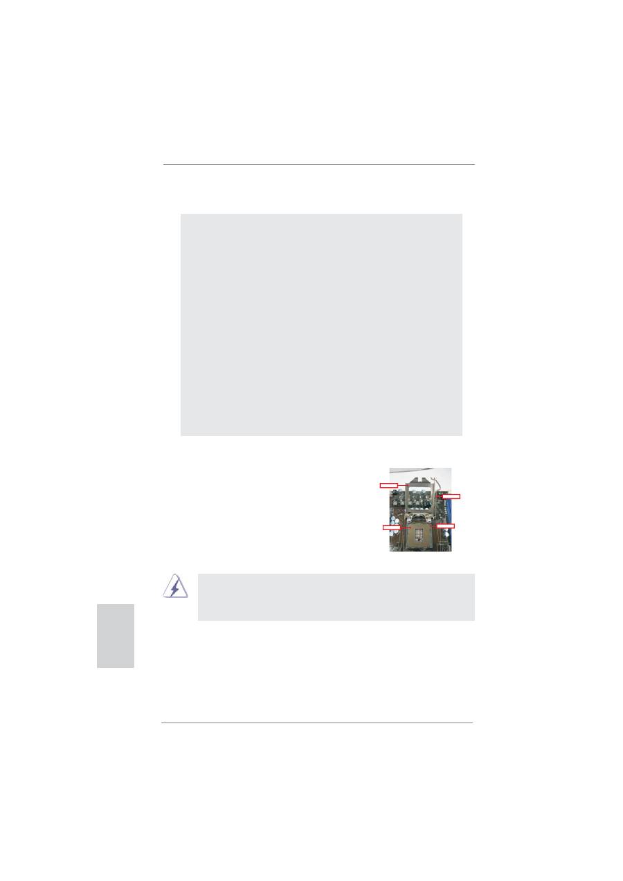
2.1 CPU Installation
Für die Installation des Intel 1155-Pin CPU
führen Sie bitte die folgenden Schritte durch.
1155-Pin Sockel Übersicht
(Ladeplatte)
(Kontaktreihe)
(Sockel)
Bevor Sie die 1155-Pin CPU in den Sockel sitzen, prüfen Sie bitte,
ob die CPU-Ober
fl
äche sauber ist und keine der Kontakte verbogen
sind. Setzen Sie die CPU nicht mit Gewalt in den Sockel, dies kann
die CPU schwer beschädigen.
Deutsch
