ASRock Fatal1ty X79 Professional – страница 2
Инструкция к Материнской Плате ASRock Fatal1ty X79 Professional
TM
TM
TM
TM
2.5 SLI
, 3-Way SLI
, 4-Way SLI
and Quad SLI
Operation
Guide
®
TM
TM
TM
This motherboard supports NVIDIA
SLI
, 3-Way SLI
, 4-Way SLI
and Quad
TM
SLI
(Scalable Link Interface) technology that allows you to install up to four
®
TM
identical PCI Express x16 graphics cards. Currently, NVIDIA
SLI
technology
®
TM
TM
®
supports Windows
XP / XP 64-bit / Vista
/ Vista
64-bit / 7 / 7 64-bit OS. NVIDIA
TM
TM
TM
®
TM
3-Way SLI
, 4-Way SLI
and Quad SLI
technology supports Windows
Vista
/
TM
Vista
64-bit / 7 / 7 64-bit OS only. Please follow the installation procedures in this
section.
Requirements
TM
TM
1. For SLI
technology, you should have two identical SLI
-ready graphics
®
TM
cards that are NVIDIA
certied. For 3-Way SLI
technology you should
TM
have three, whereas for 4-Way SLI
technology you should have four. For
TM
TM
Quad SLI
technology, you should have two identical Quad SLI
-ready
®
graphics cards that are NVIDIA
certied.
®
TM
2. Make sure that your graphics card driver supports NVIDIA
SLI
technology
(driver version 280.41 and later). Download the driver from NVIDIA website
(www.nvidia.com).
3. Make sure that your power supply unit (PSU) can provide at least the
®
minimum power required by your system. It is recommended to use NVIDIA
®
certied PSU. Please refer to NVIDIA
website for details.
2.5.1 Graphics Card Setup
TM
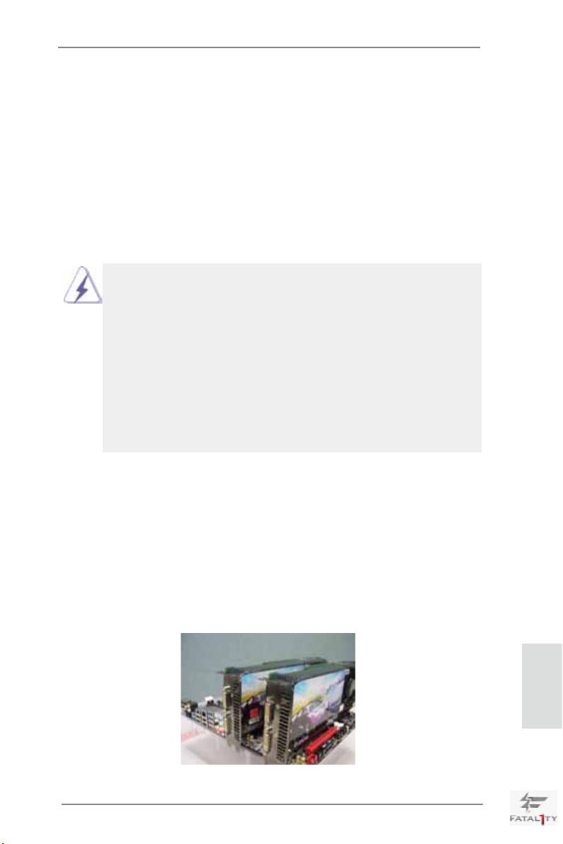
2.5.1.1 Installing Two SLI
-Ready Graphics Cards
TM
®
Step 1. Install the identical SLI
-ready graphics cards that are NVIDIA
certied
because different types of graphics cards will not work together properly.
(Even the GPU chips version shall be the same.) Insert one graphics card
into PCIE1 slot and the other graphics card to PCIE4 slot. Make sure that
the cards are properly seated on the slots.
English
21
Fatal1ty X79 Professional Series Motherboard
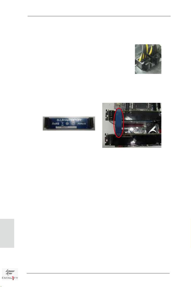
Step2. If required, connect the auxiliary power source to the PCI Express graph-
ics cards.
Step3. Align and insert the ASRock SLI_Bridge_3S Card to the goldngers on
each graphics card. Make sure the ASRock SLI_Bridge_3S Card is rmly
in place.
ASRock SLI_Bridge_3S Card
Step4. Connect a VGA cable or a DVI cable to the monitor connector or the DVI
connector of the graphics card that is inserted to PCIE1 slot.
English
22
Fatal1ty X79 Professional Series Motherboard
TM
2.5.1.2 Installing Three SLI
-Ready Graphics Cards
TM
®
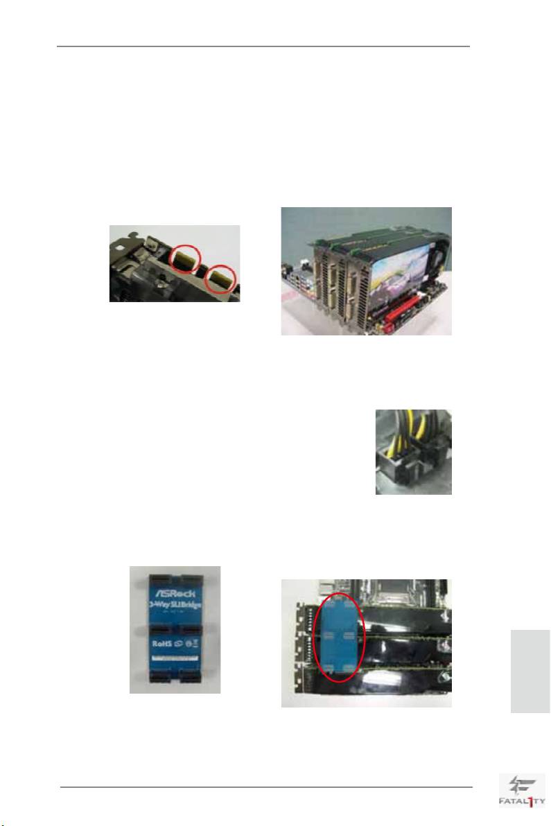
Step 1. Install the identical 3-Way SLI
-ready graphics cards that are NVIDIA
certied because different types of graphics cards will not work together
properly. (Even the GPU chips version shall be the same.) Each graph-
ics card should have two goldngers for the 3-Way SLI Bridge connector.
Insert one graphics card into PCIE1 slot, another graphics card to PCIE2
slot, and the other graphics card to PCIE4 slot. Make sure that the cards
are properly seated on the slots.
Two Goldngers
Step2. Connect the auxiliary power source to the PCI Express graphics card.
Please make sure that both power connectors on the PCI Express graph-
ics card are connected. Repeat this step on the three graphics cards.
Step3. Align and insert ASRock 3-Way SLI Bridge Card to the goldfingers on
each graphics card. Make sure ASRock 3-Way SLI Bridge Card is rmly in
place.
English
ASRock 3-Way SLI Bridge Card
Step4. Connect a VGA cable or a DVI cable to the monitor connector or the DVI
connector of the graphics card that is inserted to PCIE1 slot.
23
Fatal1ty X79 Professional Series Motherboard
TM
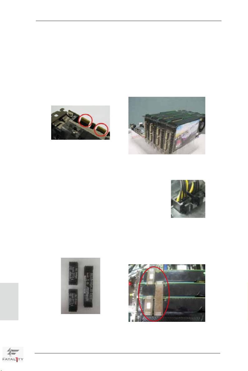
2.5.1.3 Installing Four SLI
-Ready Graphics Cards
TM
®
Step 1. Install the identical 4-Way SLI
-ready graphics cards that are NVIDIA
certied because different types of graphics cards will not work together
properly. (Even the GPU chips version shall be the same.) Each graphics
card should have two goldngers for the ASRock SLI Bridge Card connec-
tors. Insert one graphics card into the PCIE1 slot, another graphics card
into the PCIE2 slot, the third graphics card into the PCIE4 slot and the last
graphics card into the PCIE5 slot. Make sure that the cards are properly
seated on the slots.
Two Goldngers
Step2. Connect the auxiliary power source to the PCI Express graphics card.
Please make sure that both power connectors on the PCI Express graph-
ics card are connected. Repeat this step on the other graphics cards.
Step3. Align and insert an ASRock SLI Bridge Card to the goldngers of the rst
and second graphics card. Install the second ASRock SLI Bridge Card to
the goldngers of the third and fourth graphics card. Connect the second
and the fourth graphics card with the ASRock SLI_Bridge_3S Card. Make
sure the ASRock SLI Bridge Cards are rmly in place.
English
2 ASRock SLI_Bridge Cards
and an ASRock SLI_Bridge_3S Card
Step4. Connect a VGA cable or a DVI cable to the monitor connector or the DVI
connector of the graphics card that is inserted to PCIE1 slot.
24
Fatal1ty X79 Professional Series Motherboard
2.5.2 Driver Installation and Setup
Install the graphics card drivers to your system. After that, you can enable the Multi-
®
Graphics Processing Unit (GPU) feature in the NVIDIA
nView system tray utility.
Please follow the below procedures to enable the multi-GPU feature.
®
For Windows
XP / XP 64-bit OS:
TM
(For SLI
mode only)
®
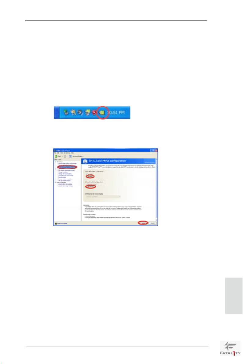
A. Double-click NVIDIA Settings icon on your Windows
taskbar.
B. From the pop-up menu, select Set SLI and PhysX conguration. In
Set PhysX GPU acceleration item, please select Enabled. In Select
an SLI conguration item, please select Enable SLI. And click Apply.
C. Reboot your system.
TM
D. You can freely enjoy the benets of SLI
.
English
25
Fatal1ty X79 Professional Series Motherboard
®
TM
TM
For Windows
Vista
/ Vista
64-bit / 7 / 7 64-bit OS:
TM
TM
(For SLI
and Quad SLI
mode)
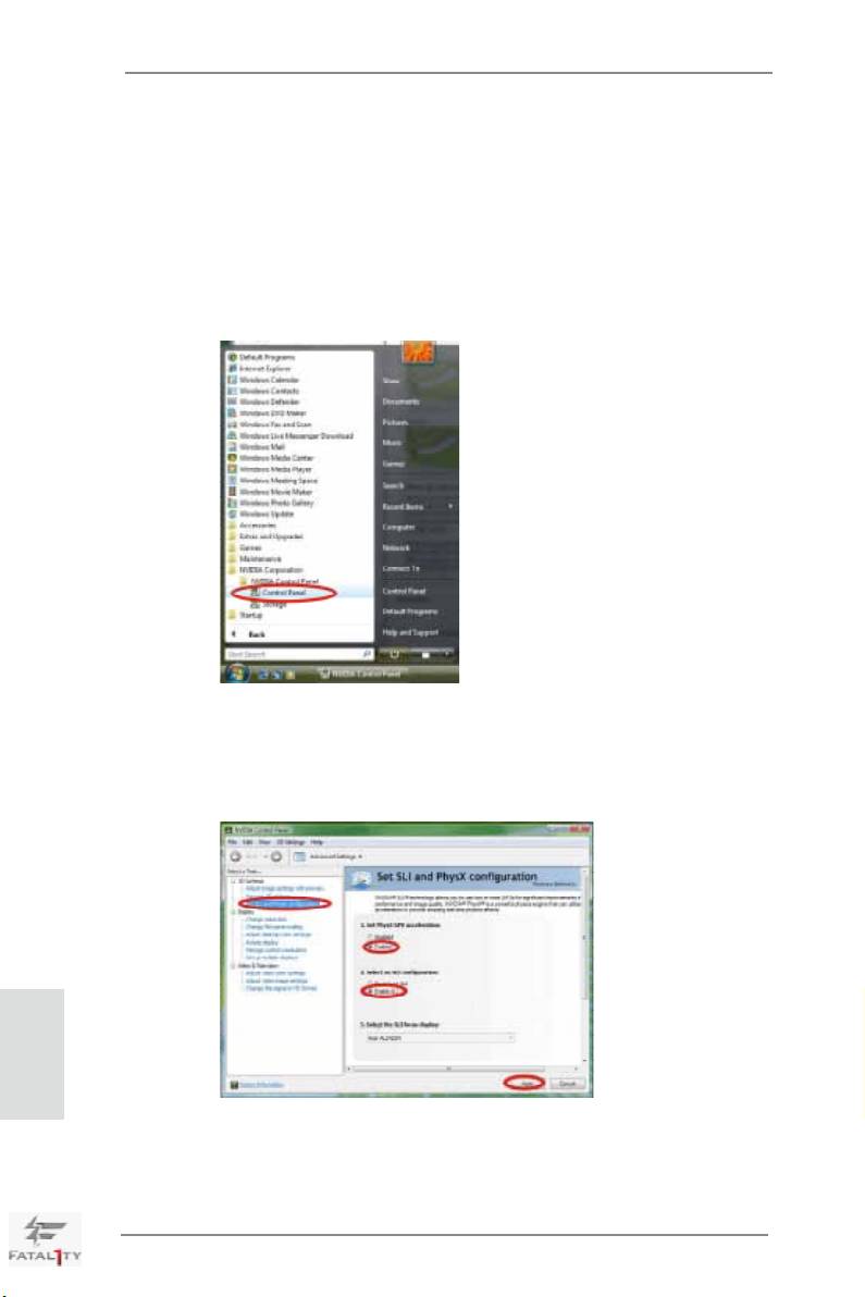
A. Click the Start icon on your Windows taskbar.
B. From the pop-up menu, select All Programs, and then click NVIDIA
Corporation.
C. Select NVIDIA Control Panel tab.
D. Select Control Panel tab.
E. From the pop-up menu, select Set SLI and PhysX conguration. In
Set PhysX GPU acceleration item, please select Enabled.
F. In Select an SLI conguration item, please select Enable SLI. And
click Apply.
English
G. Reboot your system.
TM
TM
H. You can freely enjoy the benets of SLI
or Quad SLI
.
26
Fatal1ty X79 Professional Series Motherboard
®
TM
TM
For Windows
Vista
/ Vista
64-bit / 7 / 7 64-bit OS:
TM
TM
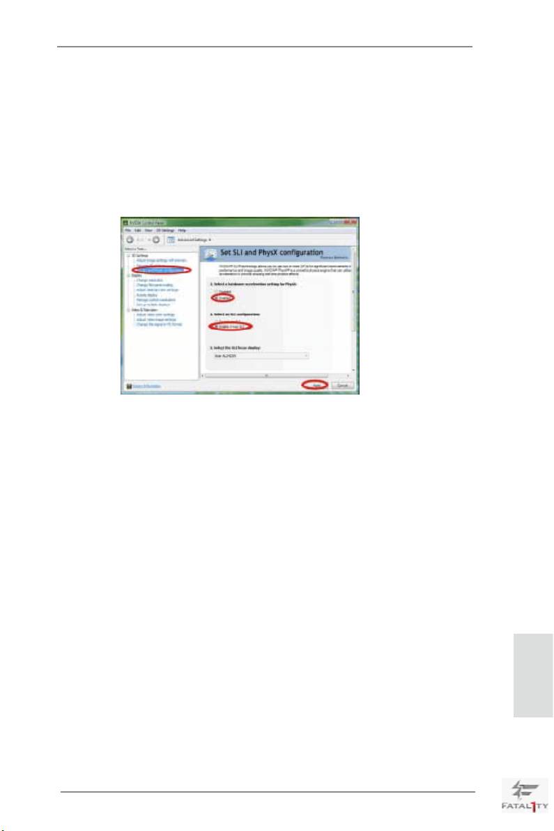
(For 3-Way SLI
or 4-Way SLI
mode)
A. Follow steps A to E on page 26.
B. In Select an SLI conguration item, please select Enable 3-way SLI
or Enable 4-way SLI and click Apply.
C. Reboot your system.
TM
TM
D. You can freely enjoy the benets of 3-Way SLI
or 4-Way SLI
.
TM
®
* SLI
appearing here is a registered trademark of NVIDIA
Technologies Inc., and is used only
for identication or explanation and to the owners’ benet, without intent to infringe.
English
27
Fatal1ty X79 Professional Series Motherboard
TM
TM
TM
2.6 CrossFireX
, 3-Way CrossFireX
, 4-Way CrossFireX
and
TM
Quad CrossFireX
Operation Guide
TM
TM
TM
This motherboard supports CrossFireX
, 3-way CrossFireX
, 4-way CrossFireX
TM
TM
and Quad CrossFireX
. CrossFireX
technology offers the most advantageous
means available of combining multiple high performance Graphics Processing
Units (GPU) in a single PC. Combining a range of different operating modes with
TM
intelligent software design and an innovative interconnect mechanism, CrossFireX
enables the highest possible level of performance and image quality in any 3D
TM
®
application. Currently CrossFireX
is supported with Windows
XP with Service
TM
TM
TM
Pack 2 / Vista
/ 7 OS. 3-way CrossFireX
, 4-way CrossFireX
and Quad
TM
®
TM
CrossFireX
are supported with Windows
Vista
/ 7 OS only. Please check AMD’s
TM
TM
website for ATI
CrossFireX
driver updates.
1. If a customer incorrectly congures their system they will not see the performance
TM
TM
TM
benets of CrossFireX
. All three CrossFireX
components, a CrossFireX
TM
TM
Ready graphics card, a CrossFireX
Ready motherboard and a CrossFireX
Edition co-processor graphics card, must be installed correctly to benet from the
TM
CrossFireX
multi-GPU platform.
TM
2. If you pair a 12-pipe CrossFireX
Edition card with a 16-pipe card, both cards
TM
will operate as 12-pipe cards while in CrossFireX
mode.
2.6.1 Graphics Card Setup
TM
2.6.1.1 Installing Two CrossFireX
-Ready Graphics Cards
TM
TM
Different CrossFireX
cards may require different methods to enable CrossFireX
feature. In below procedures, we use Radeon HD 5770 as the example graphics
TM
card. For other CrossFireX
cards that AMD has released or will release in the
future, please refer to AMD graphics card manuals for detailed installation guide.
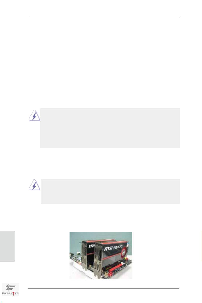
Step 1. Insert one Radeon graphics card into PCIE1 slot and the other Radeon
graphics card to PCIE4 slot. Make sure that the cards are properly seated
on the slots.
English
28
Fatal1ty X79 Professional Series Motherboard
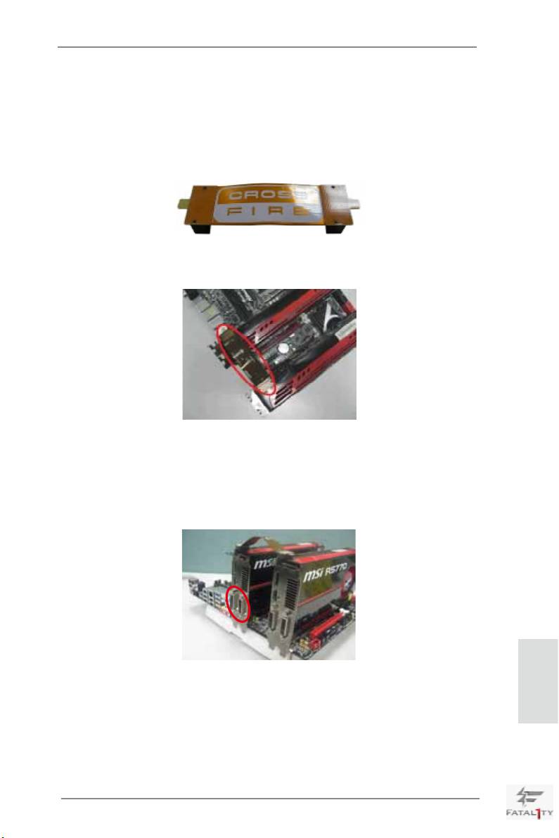
Step 2. Connect two Radeon graphics cards by installing CrossFire Bridge on
CrossFire Bridge Interconnects on the top of Radeon graphics cards.
(CrossFire Bridge is provided with the graphics card you purchase, not
bundled with this motherboard. Please refer to your graphics card vendor
for details.)
CrossFire Bridge
Step 3. Connect the DVI monitor cable to the DVI connector on the Radeon graph-
ics card on PCIE1 slot. (You may use the DVI to D-Sub adapter to convert
the DVI connector to D-Sub interface, and then connect the D-Sub monitor
cable to the DVI to D-Sub adapter.)
English
29
Fatal1ty X79 Professional Series Motherboard
TM
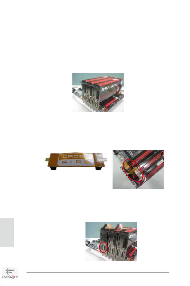
2.6.1.2 Installing Three CrossFireX
-Ready Graphics Cards
TM
Step 1. Install the identical 3-Way CrossFireX
-ready graphics cards that are
®
AMD
certified because different types of graphics cards will not work
together properly. (Even the GPU chips version shall be the same.) Insert
one graphics card into PCIE1 slot, another graphics card to PCIE2 slot,
and the other graphics card to PCIE4 slot. Make sure that the cards are
properly seated on the slots.
TM
Step 2. Use one CrossFire
Bridge to connect Radeon graphics cards on PCIE1
TM
and PCIE2 slots, and use the other CrossFire
Bridge to connect Radeon
TM
graphics cards on PCIE2 and PCIE4 slots. (CrossFire
Bridge is provided
with the graphics card you purchase, not bundled with this motherboard.
Please refer to your graphics card vendor for details.)
TM
CrossFire
Bridge
Step 3. Connect the DVI monitor cable to the DVI connector on the Radeon graph-
ics card on PCIE1 slot. (You may use the DVI to D-Sub adapter to convert
the DVI connector to D-Sub interface, and then connect the D-Sub monitor
cable to the DVI to D-Sub adapter.)
English
30
Fatal1ty X79 Professional Series Motherboard
TM
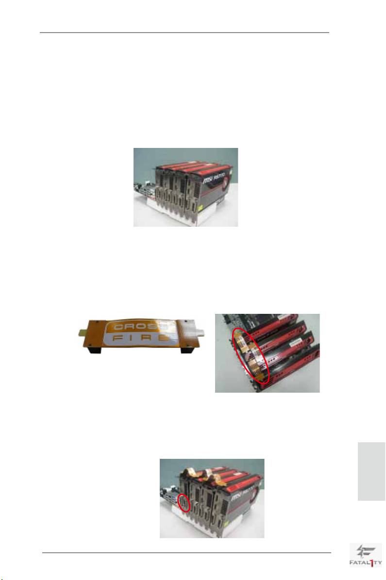
2.6.1.3 Installing Four CrossFireX
-Ready Graphics Cards
TM
Step 1. Install the identical 4-Way CrossFireX
-ready graphics cards that are
®
AMD
certified because different types of graphics cards will not work
together properly. (Even the GPU chips version shall be the same.) Insert
one graphics card into PCIE1 slot, another graphics card into PCIE2 slot,
the third graphics card into PCIE4 slot and the last graphics card into
PCIE5 slot. Make sure that the cards are properly seated on the slots.
TM
Step 2. Use one CrossFire
Bridge to connect Radeon graphics cards on PCIE1
TM
and PCIE2 slots, another CrossFire
Bridge to connect Radeon graphics
TM
cards on PCIE2 and PCIE4 slots, and use the third CrossFire
Bridge to
TM
connect Radeon graphics cards on PCIE4 and PCIE5 slots. (CrossFire
Bridge is provided with the graphics card you purchase, not bundled with
this motherboard. Please refer to your graphics card vendor for details.)
TM
CrossFire
Bridge
Step 3. Connect the DVI monitor cable to the DVI connector on the Radeon graph-
ics card on PCIE1 slot. (You may use the DVI to D-Sub adapter to convert
the DVI connector to D-Sub interface, and then connect the D-Sub monitor
cable to the DVI to D-Sub adapter.)
English
31
Fatal1ty X79 Professional Series Motherboard
2.6.2 Driver Installation and Setup
Step 1. Power on your computer and boot into OS.
Step 2. Remove the AMD driver if you have any VGA driver installed in your
system.
The Catalyst Uninstaller is an optional download. We recommend using this utility to
uninstall any previously installed Catalyst drivers prior to installation.
TM
Please check AMD’s website for ATI
driver updates.
Step 3. Install the required drivers to your system.
®
For Windows
XP OS:
®
A. AMD recommends Windows
XP Service Pack 2 or higher to be
®
installed (If you have Windows
XP Service Pack 2 or higher installed
in your system, there is no need to download it again):
http://www.microsoft.com/windowsxp/sp2/default.mspx
B. You must have Microsoft .NET Framework installed prior to
downloading and installing the CATALYST Control Center. Please
check Microsoft website for details.
®
TM
For Windows
7 / Vista
OS:
Install the CATALYST Control Center. Please check AMD’s website for de-
tails.
Step 4. Restart your computer.
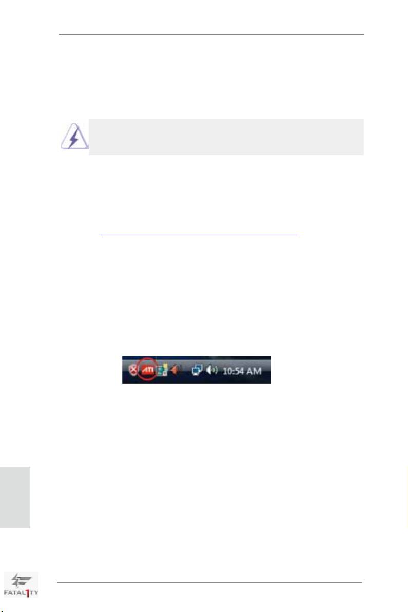
Step 5. Install the VGA card driver to your system, and restart your computer.
®
Then you will nd “ATI Catalyst Control Center” on your Windows
taskbar.
ATI Catalyst Control Center
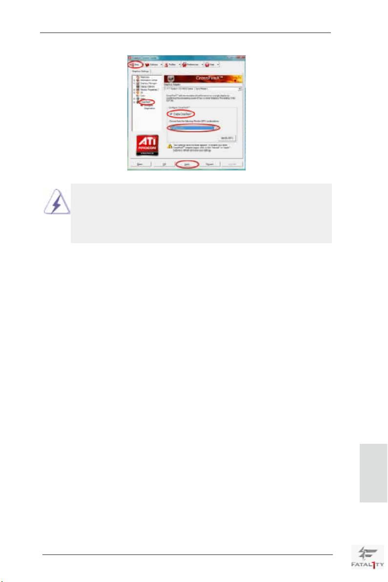
Step 6. Double-click “ATI Catalyst Control Center”. Click “View”, select “CrossFi-
TM
TM
reX
”, and then check the item “Enable CrossFireX
”. Select “2 GPUs”
and click “Apply” (if you install two Radeon graphics cards). Select “3
GPUs” and click “OK” (if you install three Radeon graphics cards). Select “4
GPUs” and click “OK” (if you install four Radeon graphics cards).
English
32
Fatal1ty X79 Professional Series Motherboard
TM
TM
Although you have selected the option “Enable CrossFire
”, the CrossFireX
function may not work actually. Your computer will automatically reboot. After
TM
restarting your computer, please conrm whether the option “Enable CrossFire
” in
“ATI Catalyst Control Center” is selected or not; if not, please select it again, and then
TM
you are able to enjoy the benets of CrossFireX
.
TM
TM
Step 7. You can freely enjoy the benets of CrossFireX
, 3-Way CrossFireX
,
TM
TM
4-Way CrossFireX
or Quad CrossFireX
.
TM
* CrossFireX
appearing here is a registered trademark of AMD Technologies Inc., and is used
only for identication or explanation and to the owners’ benet, without intent to infringe.
TM
* For further information of AMD CrossFireX
technology, please check AMD’s website for
updates and details.
2.7 Surround Display Feature
This motherboard supports Surround Display upgrade. With the external add-on PCI
Express VGA cards, you can easily enjoy the benets of Surround Display feature.
For detailed instructions, please refer to the document at the following path in the
Support CD:
..\ Surround Display Information
English
33
Fatal1ty X79 Professional Series Motherboard
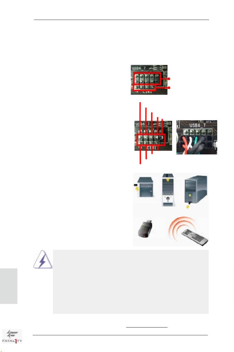
2.8 ASRock Smart Remote Installation Guide
ASRock Smart Remote is only used for ASRock motherboard with CIR header.
Please refer to below procedures for the quick installation and usage of ASRock
Smart Remote.
Step1. Find the CIR header located next
to the USB 2.0 header on ASRock
USB 2.0 header (9-pin, black)
motherboard.
CIR header (4-pin, gray)
USB_PWR
Step2. Connect the front USB cable to the
P-
USB 2.0 header (as below, pin 1-5)
P+
and the CIR header. Please make
GND
DUMMY
sure the wire assignments and the
pin assignments are matched
correctly.
GND
IRTX
IRRX
ATX+5VSB
Step3. Install Multi-Angle CIR Receiver to
the front USB port. If Multi-Angle
CIR Receiver cannot successfully
receive the infrared signals from
MCE Remote Controller, please try
to install it to the other front USB
port.
3 CIR sensors in different angles
1. Only one of the front USB port can support CIR function. When
the CIR function is enabled, the other port will remain USB
function.
2. Multi-Angle CIR Receiver is used for front USB only. Please do
English
not use the rear USB bracket to connect it on the rear panel.
Multi-Angle CIR Receiver can receive the multi-direction infrared
signals (top, down and front), which is compatible with most of
the chassis on the market.
3. The Multi-Angle CIR Receiver does not support Hot-Plug
function. Please install it before you boot the system.
* ASRock Smart Remote is only supported by some of ASRock motherboards. Please refer to
ASRock website for the motherboard support list: http://www.asrock.com
34
Fatal1ty X79 Professional Series Motherboard
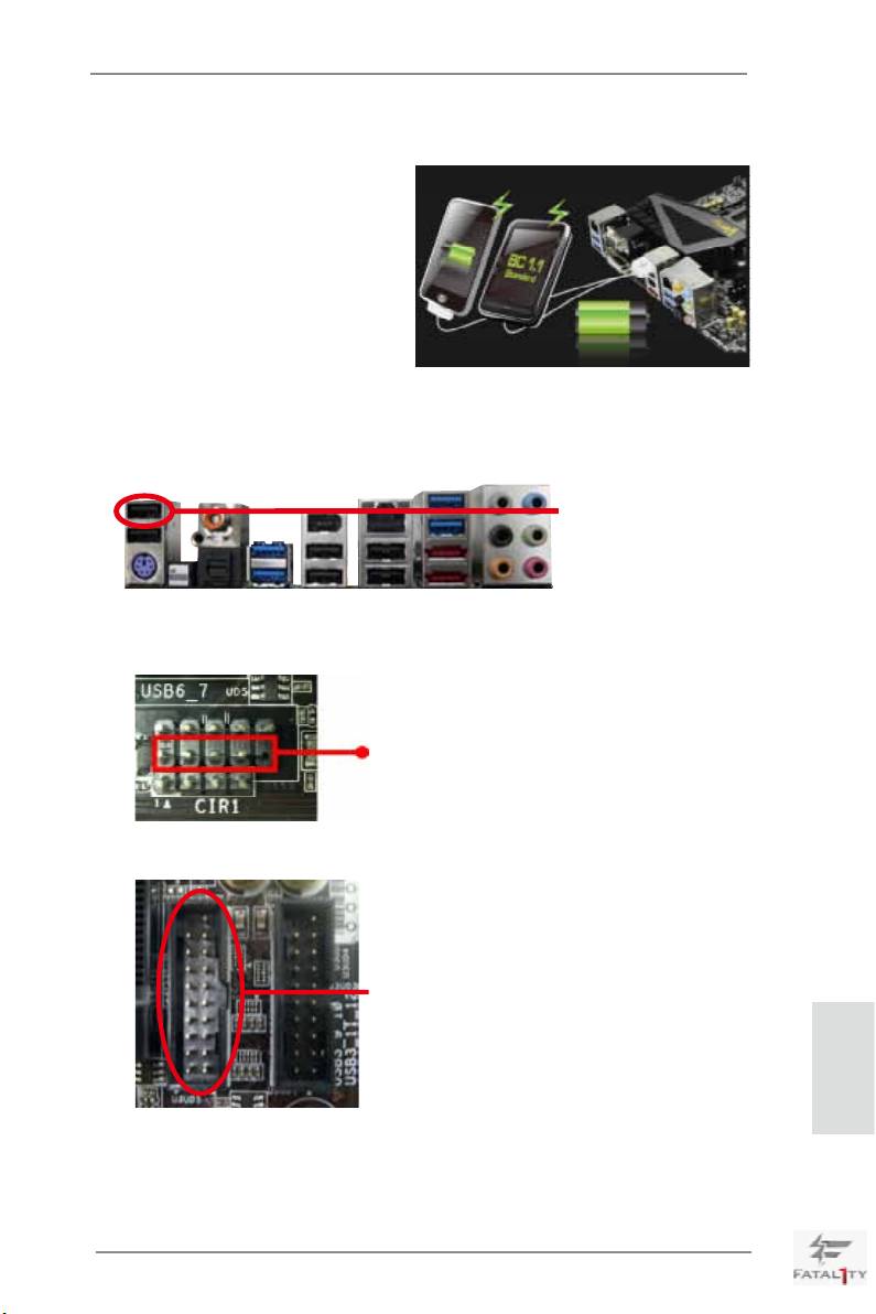
2.9 ASRock XFast Charger Operation Guide
ASRock XFast Charger is the best and
fastest technology to charge your mobile
devices via PC. With the superb XFast
Charger USB port, users are assured to
enjoy the quick charging experience
anytime. In addition to Apple devices, it
is also capable of Charging the BC 1.1
standard smart devices. Please refer to
below instruction for proper operation.
This motherboard provides three USB ports for ASRock XFast Charger:
1. USB 2.0 port (USB0) on the I/O panel
see p.5 No. 1
2. USB 2.0 port (USB_6) header
see p.4 No. 29
3. USB 3.0 port (USB3_5) header
see p.4 No. 8
English
With ASRock XFast Charger feature, you can freely enjoy the quick charging
convenience by installing the USB cable on these three ports.
35
Fatal1ty X79 Professional Series Motherboard
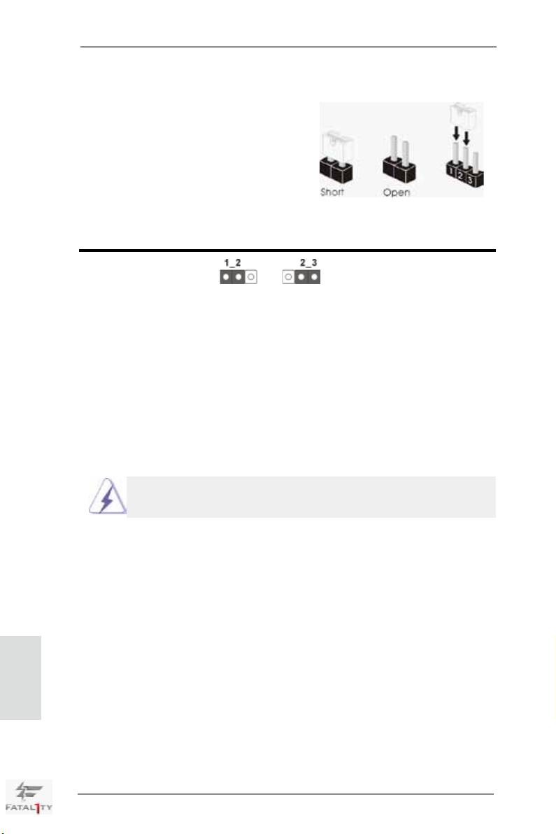
2.10 Jumpers Setup
The illustration shows how jumpers are
setup. When the jumper cap is placed on
pins, the jumper is “Short”. If no jumper cap
is placed on pins, the jumper is “Open”. The
illustration shows a 3-pin jumper whose
pin1 and pin2 are “Short” when jumper cap
is placed on these 2 pins.
Jumper Setting Description
Clear CMOS Jumper
(CLRCMOS1)
(see p.4, No. 25)
Clear CMOSDefault
Note: CLRCMOS1 allows you to clear the data in CMOS. To clear and reset the sys-
tem parameters to default setup, please turn off the computer and unplug the
power cord from the power supply. After waiting for 15 seconds, use a jumper
cap to short pin2 and pin3 on CLRCMOS1 for 5 seconds. However, please do
not clear the CMOS right after you update the BIOS. If you need to clear the
CMOS when you just nish updating the BIOS, you must boot up the system
rst, and then shut it down before you do the clear-CMOS action. Please be
noted that the password, date, time, user default prole, 1394 GUID and MAC
address will be cleared only if the CMOS battery is removed.
The Clear CMOS Switch has the same function as the Clear CMOS
jumper.
English
36
Fatal1ty X79 Professional Series Motherboard
2.11 Onboard Headers and Connectors
Onboard headers and connectors are NOT jumpers. Do NOT place
jumper caps over these headers and connectors. Placing jumper caps
over the headers and connectors will cause permanent damage of the
motherboard!
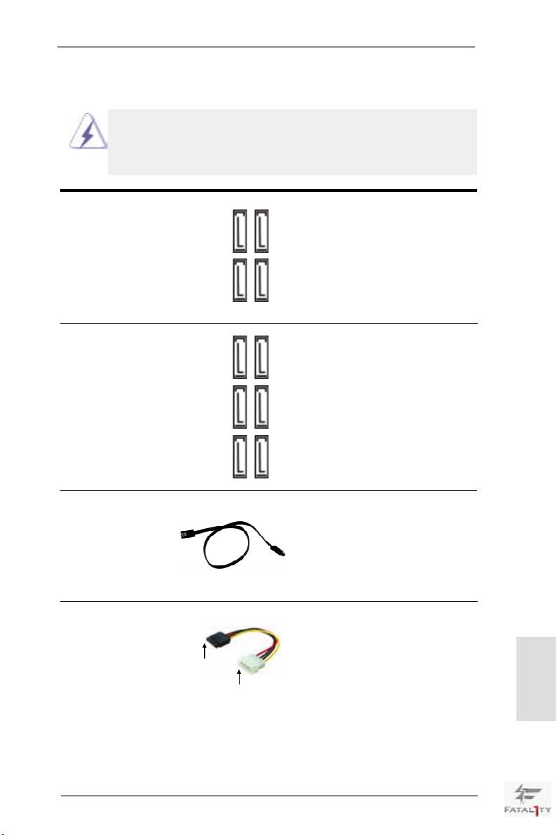
Serial ATA2 Connectors These four Serial ATA2 (SATA2)
(SATA2_0_1: see p.4, No. 13)
connectors support SATA data
(SATA2_2_3: see p.4, No. 12)
cables for internal storage
devices. The current SATA2
interface allows up to 3.0 Gb/s
data transfer rate.
SATA2_0 SATA2_3
SATA2_1 SATA2_2
Serial ATA3 Connectors These six Serial ATA3
(SATA3_0_1: see p.4, No. 14)
(SATA3) connectors support
SATA3_1
SATA3_0
(SATA3_M0_M1: see p.4, No. 15)
SATA data cables for internal
(SATA3_M2_M3: see p.4, No. 16)
storage devices. The current
SATA3 interface allows up to
6.0 Gb/s data transfer rate.
SATA3_M3 SATA3_M1
SATA3_M2 SATA3_M0
Serial ATA (SATA) Either end of the SATA data
Data Cable cable can be connected to the
(Optional)
SATA / SATA2 / SATA3 hard
disk or the SATA2 / SATA3
connector on this motherboard.
Serial ATA (SATA) Please connect the black end
Power Cable of SATA power cable to the
(Optional)
power connector on each drive.
connect to the SATA
Then connect the white end of
HDD power connector
SATA power cable to the power
connect to the
power supply
English
connector of the power supply.
37
Fatal1ty X79 Professional Series Motherboard
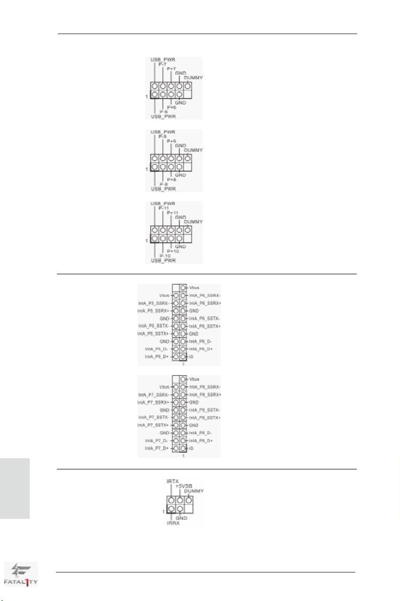
USB 2.0 Headers Besides six default USB 2.0
(9-pin USB_6_7)
ports on the I/O panel, there are
(see p.4 No. 29)
three USB 2.0 headers on this
motherboard. Each USB 2.0
header can support two USB 2.0
ports.
(9-pin USB_8_9)
(see p.4 No. 28)
(9-pin USB_10_11)
(see p.4 No. 27)
USB 3.0 Header Besides four default USB 3.0
(19-pin USB3_5_6)
ports on the I/O panel, there are
(see p.4 No. 8)
two USB 3.0 headers on this
motherboard. Each USB 3.0
header can support two USB 3.0
ports.
(19-pin USB3_7_8)
(see p.4 No. 9)
English
Infrared Module Header This header supports an
(5-pin IR1)
optional wireless transmitting
(see p.4 No. 37)
and receiving infrared module.
38
Fatal1ty X79 Professional Series Motherboard
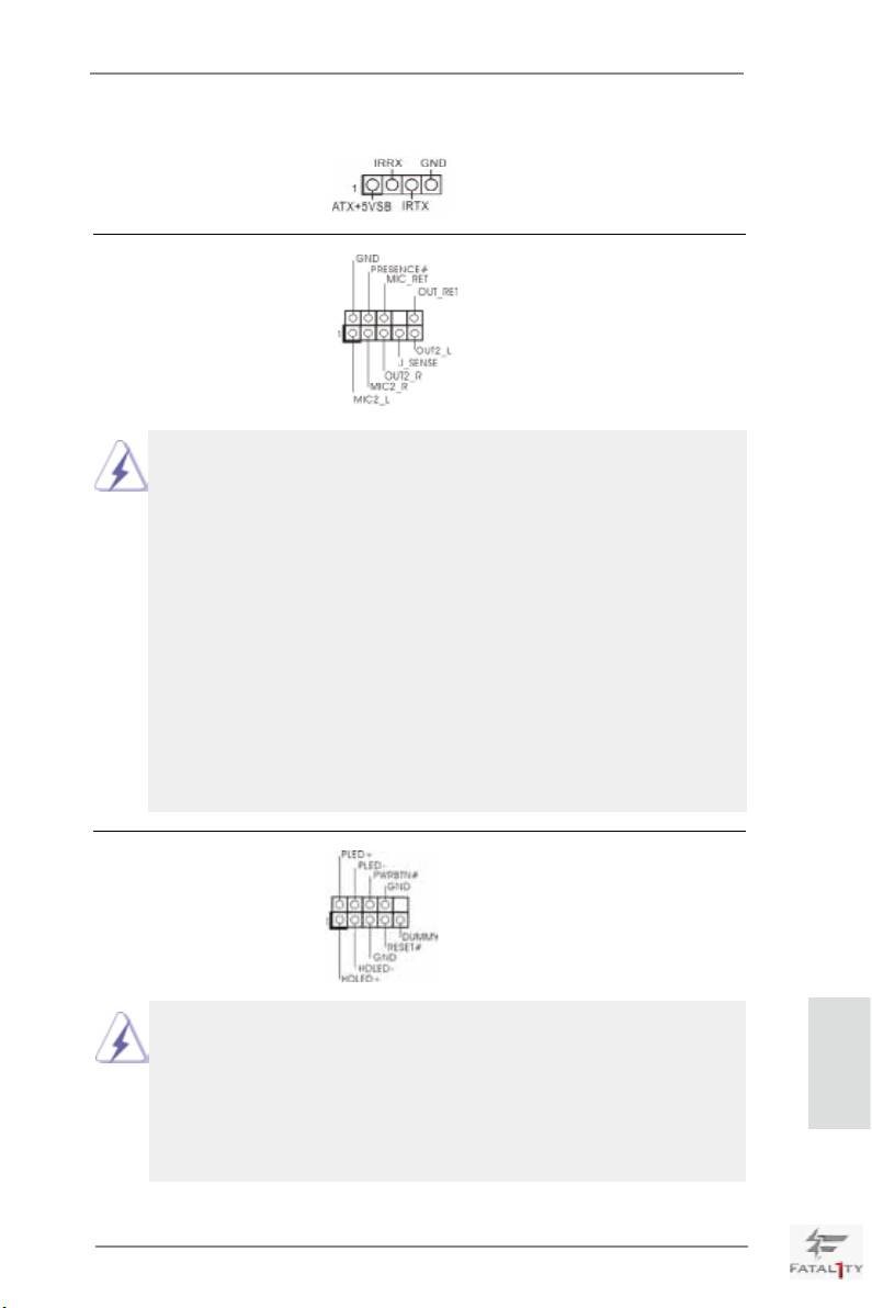
Consumer Infrared Module Header This header can be used to
(4-pin CIR1)
connect the remote controller
(see p.4 No. 30)
receiver.
Front Panel Audio Header This is an interface for front
(9-pin HD_AUDIO1)
panel audio cable that allows
(see p.4 No. 35)
convenient connection and
control of audio devices.
1. High Denition Audio supports Jack Sensing, but the panel wire on the
chassis must support HDA to function correctly. Please follow the
instruction in our manual and chassis manual to install your system.
2. If you use AC’97 audio panel, please install it to the front panel audio
header as below:
A. Connect Mic_IN (MIC) to MIC2_L.
B. Connect Audio_R (RIN) to OUT2_R and Audio_L (LIN) to OUT2_L.
C. Connect Ground (GND) to Ground (GND).
D. MIC_RET and OUT_RET are for HD audio panel only. You don’t
need to connect them for AC’97 audio panel.
E. To activate the front mic.
®
For Windows
XP / XP 64-bit OS:
Select “Mixer”. Select “Recorder”. Then click “FrontMic”.
®
TM
TM
For Windows
7 / 7 64-bit / Vista
/ Vista
64-bit OS:
Go to the “FrontMic” Tab in the Realtek Control panel. Adjust
“Recording Volume”.
System Panel Header This header accommodates
(9-pin PANEL1)
several system front panel
(see p.4 No. 22)
functions.
Connect the power switch, reset switch and system status indicator on the
chassis to this header according to the pin assignments below. Note the
positive and negative pins before connecting the cables.
English
PWRBTN (Power Switch):
Connect to the power switch on the chassis front panel. You may congure
the way to turn off your system using the power switch.
39
Fatal1ty X79 Professional Series Motherboard
RESET (Reset Switch):
Connect to the reset switch on the chassis front panel. Press the reset
switch to restart the computer if the computer freezes and fails to perform a
normal restart.
PLED (System Power LED):
Connect to the power status indicator on the chassis front panel. The LED
is on when the system is operating. The LED keeps blinking when the
system is in S1 sleep state. The LED is off when the system is in S3/S4
sleep state or powered off (S5).
HDLED (Hard Drive Activity LED):
Connect to the hard drive activity LED on the chassis front panel. The LED
is on when the hard drive is reading or writing data.
The front panel design may differ by chassis. A front panel module mainly
consists of power switch, reset switch, power LED, hard drive activity LED,
speaker and etc. When connecting your chassis front panel module to this
header, make sure the wire assignments and the pin assign-ments are
matched correctly.
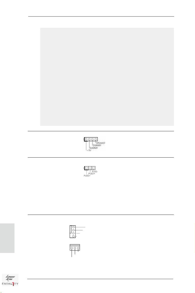
Chassis Speaker Header Please connect the chassis
(4-pin SPEAKER 1)
speaker to this header.
(see p.4 No. 21)
Power LED Header Please connect the chassis
(3-pin PLED1)
power LED to this header to
(see p.4 No. 23)
indicate system power status.
The LED is on when the system
is operating. The LED keeps
blinking in S1 state. The LED is
off in S3/S4 state or S5 state
(power off).
Chassis and Power Fan Connectors Please connect the fan cables
English
(4-pin CHA_FAN1)
to the fan connectors and match
(see p.4 No. 11)
the black wire to the ground pin.
CHA_FAN1, CHA_FAN2 and
CHA_FAN3
support Fan
(3-pin CHA_FAN2)
Control.
(see p.4 No. 20)
40
Fatal1ty X79 Professional Series Motherboard
GND
+12V
CHA_FAN_SPEED
FAN_SPEED_CONTROL
GND
+12V
CHA_FAN_SPEED
