ASRock Fatal1ty P67 Performance – страница 2
Инструкция к Материнской Плате ASRock Fatal1ty P67 Performance
Fatal1ty P67 Performance Series Motherboard
21
English
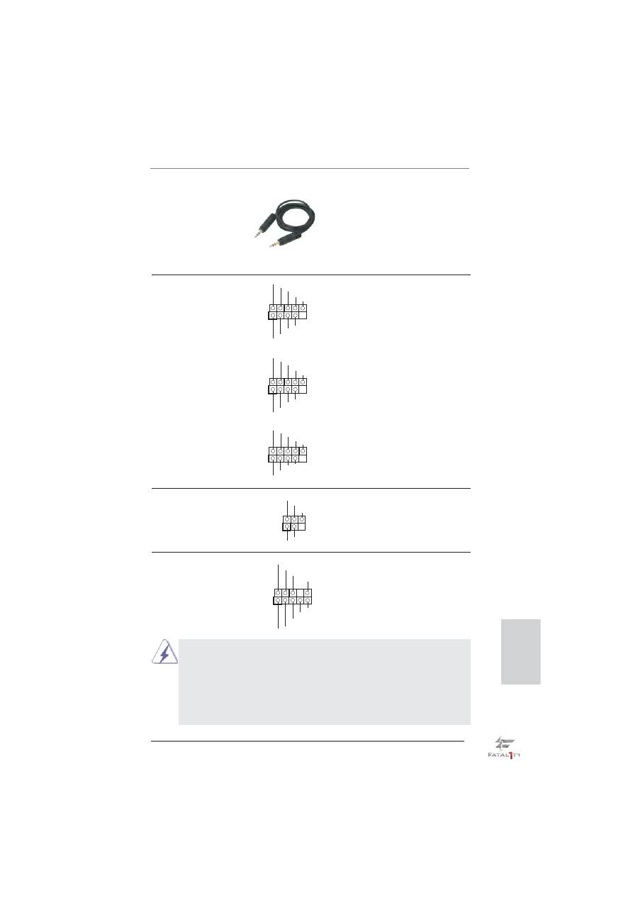
3.5mm Audio Cable
Either end of the 3.5mm audio
(Optional)
cable can be connected to the
portable audio devices, such
as MP3 player and mobile
phone or the Line-in port of
your
PC.
USB 2.0 Headers
Besides six default USB 2.0
(9-pin USB8_9)
ports on the I/O panel, there
(see p.4 No. 27)
are three USB 2.0 headers on
this motherboard. Each
USB 2.0 header can support
two USB 2.0 ports.
(9-pin USB10_11)
(see p.4 No. 26)
(9-pin USB12_13)
(see p.4 No. 25)
1
DUMMY
GND
P+13
P-13
USB_PWR
USB_PWR
GND
P+12
P-12
1
USB_PWR
P-8
GND
DUMMY
USB_PWR
P+8
GND
P-9
P+9
1
USB
_
P
W
R
P
-10
G
N
D
DU
MMY
USB
_
P
W
R
P
+10
G
N
D
P
-11
P
+11
J_SENSE
OUT2_L
1
MIC_RET
PRESENCE#
GND
OUT2_R
MIC2_R
MIC2_L
OUT_RET
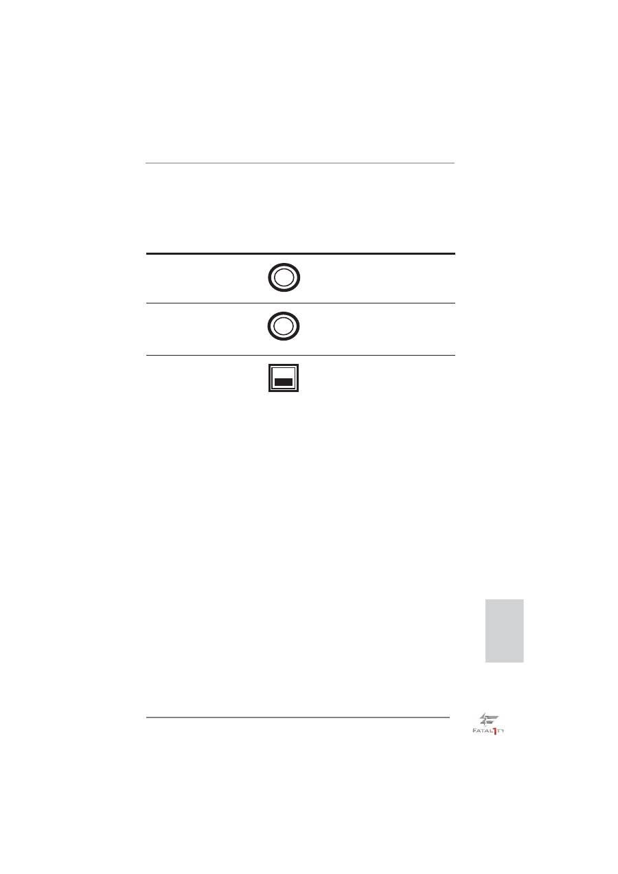
Front Panel Audio Header
This is an interface for front
(9-pin HD_AUDIO1)
panel audio cable that allows
(see p.4 No. 32)
convenient connection and
control of audio devices.
Infrared Module Header
This header supports an
(5-pin IR1)
optional wireless transmitting
(see p.4 No. 29)
and receiving infrared module.
1
IRTX
+5VSB
DUMMY
IRRX
GND
1. High De
fi
nition Audio supports Jack Sensing, but the panel wire on
the chassis must support HDA to function correctly. Please follow the
instruction in our manual and chassis manual to install your system.
2. If you use AC’97 audio panel, please install it to the front panel audio
header as below:
A. Connect Mic_IN (MIC) to MIC2_L.
B. Connect Audio_R (RIN) to OUT2_R and Audio_L (LIN) to OUT2_L.
22
Fatal1ty P67 Performance Series Motherboard
English
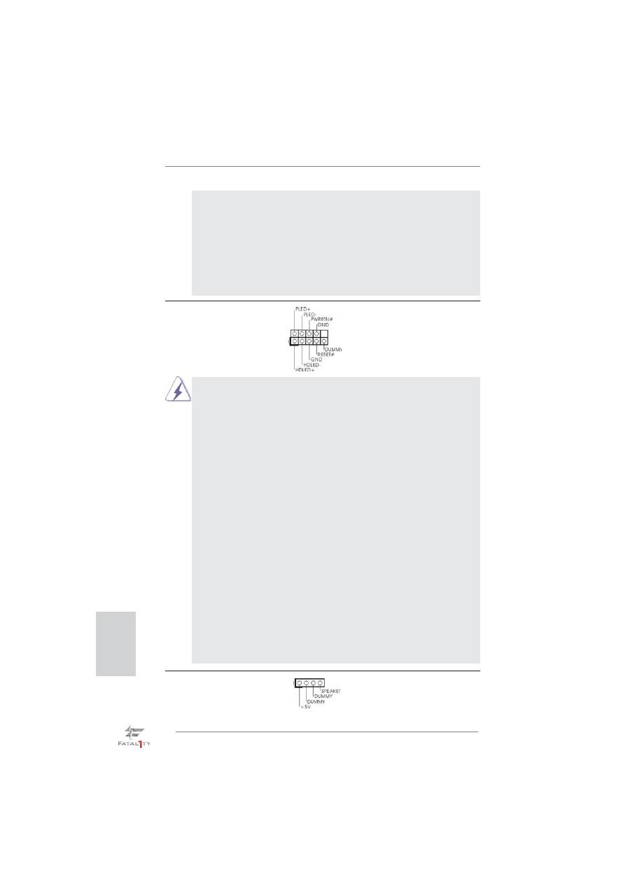
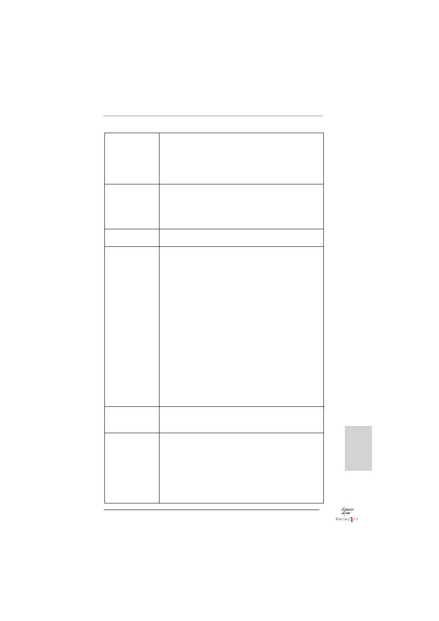
System Panel Header
This header accommodates
(9-pin PANEL1)
several system front panel
(see p.4 No. 14)
functions.
Connect the power switch, reset switch and system status indicator on the
chassis to this header according to the pin assignments below. Note the
positive and negative pins before connecting the cables.
PWRBTN (Power Switch):
Connect to the power switch on the chassis front panel. You may con
fi
gure
the way to turn off your system using the power switch.
RESET (Reset Switch):
Connect to the reset switch on the chassis front panel. Press the reset
switch to restart the computer if the computer freezes and fails to perform a
normal restart.
PLED (System Power LED):
Connect to the power status indicator on the chassis front panel. The LED
is on when the system is operating. The LED keeps blinking when the sys-
tem is in S1 sleep state. The LED is off when the system is in S3/S4 sleep
state or powered off (S5).
HDLED (Hard Drive Activity LED):
Connect to the hard drive activity LED on the chassis front panel. The LED
is on when the hard drive is reading or writing data.
The front panel design may differ by chassis. A front panel module mainly
consists of power switch, reset switch, power LED, hard drive activity LED,
speaker and etc. When connecting your chassis front panel module to this
header, make sure the wire assignments and the pin assign-ments are
matched correctly.
C. Connect Ground (GND) to Ground (GND).
D. MIC_RET and OUT_RET are for HD audio panel only. You don’t
need to connect them for AC’97 audio panel.
E. To activate the front mic.
For Windows
®
XP / XP 64-bit OS:
Select “Mixer”. Select “Recorder”. Then click “FrontMic”.
For Windows
®
7 / 7 64-bit / Vista
TM
/ Vista
TM
64-bit OS:
Go to the "FrontMic" Tab in the Realtek Control panel. Adjust
“Recording Volume”.
Chassis Speaker Header
Please connect the chassis
(4-pin SPEAKER 1)
speaker to this header.
(see p.4 No. 13)
Fatal1ty P67 Performance Series Motherboard
23
English
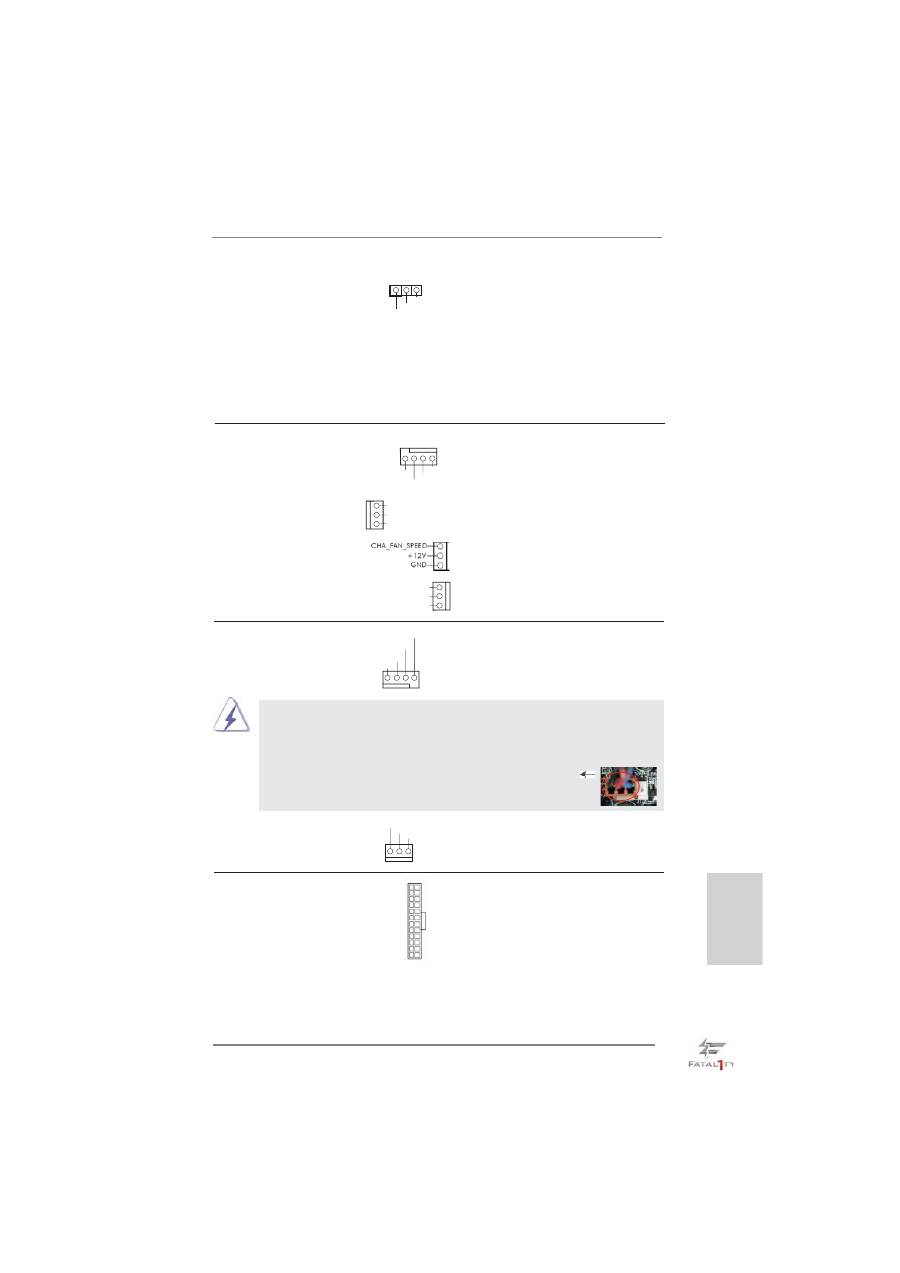
Power LED Header
Please connect the chassis
(3-pin PLED1)
power LED to this header to
(see p.4 No. 12)
indicate system power status.
The LED is on when the system
is operating. The LED keeps
blinking in S1 state. The LED is
off in S3/S4 state or S5 state
(power
off).
1
PLED+
PLED+
PLED-
Chassis and Power Fan Connectors
Please connect the fan cables
(4-pin CHA_FAN1)
to the fan connectors and
(see p.4 No. 28)
match the black wire to the
ground
pin.
(3-pin CHA_FAN2)
(see p.4 No. 10)
(3-pin CHA_FAN3)
(see p.4 No. 39)
(3-pin PWR_FAN1)
(see p.4 No. 40)
GND
+12V
CHA_FAN_SPEED
FAN_SPEED_CONTROL
GND
CHA_FAN2_PWR
CHA_FAN_SPEED
GND
+12V
PWR_FAN_SPEED
CPU Fan Connectors
Please connect the CPU fan
(4-pin CPU_FAN1)
cable to the connector and
(see p.4 No. 3)
match the black wire to the
ground
pin.
Though this motherboard provides 4-Pin CPU fan (Quiet Fan) support, the 3-Pin
CPU fan still can work successfully even without the fan speed control function.
If you plan to connect the 3-Pin CPU fan to the CPU fan connector on this
motherboard, please connect it to Pin 1-3.
3-Pin Fan Installation
Pin 1-3 Connected
GND
+12V
CPU_FAN_SPEED
FAN_SPEED_CONTROL
1 2 3 4
(3-pin CPU_FAN2)
(see p.4 No. 2)
GND
+12V
CPU_FAN_SPEED
ATX Power Connector
Please connect an ATX power
(24-pin ATXPWR1)
supply to this connector.
(see p.4 No. 7)
12
1
24
13
24
Fatal1ty P67 Performance Series Motherboard
English
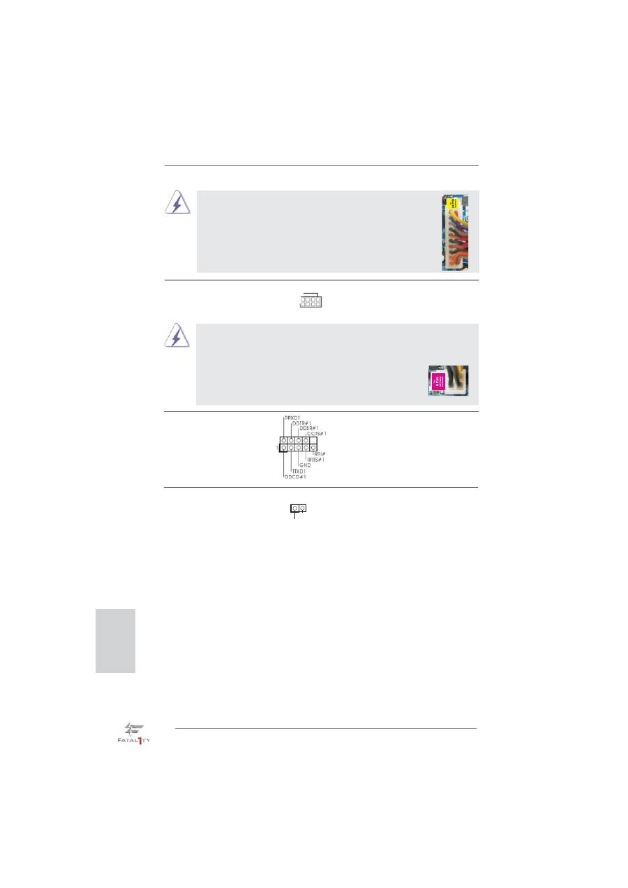
20-Pin ATX Power Supply Installation
Though this motherboard provides 24-pin ATX power connector,
it can still work if you adopt a traditional 20-pin ATX power supply.
To use the 20-pin ATX power supply, please plug your
power supply along with Pin 1 and Pin 13.
12
1
24
13
ATX 12V Power Connector
Please connect an ATX 12V
(8-pin ATX12V1)
power supply to this connector.
(see p.4 No. 1)
4-Pin ATX 12V Power Supply Installation
Though this motherboard provides 8-pin ATX 12V power connector, it can still work
if you adopt a traditional 4-pin ATX 12V power supply. To use the 4-pin ATX power
supply, please plug your power supply along with Pin 1 and Pin 5.
8 5
4 1
8
5
4
1
HDMI_SPDIF Header
HDMI_SPDIF header, providing
(2-pin HDMI_SPDIF1)
SPDIF audio output to HDMI
(see p.4 No. 33)
VGA card, allows the system to
connect HDMI Digital TV/
projector/LCD devices. Please
connect the HDMI_SPDIF
connector of HDMI VGA card to
this
header.
SPDIFOUT
GND
1
Serial port Header
This COM1 header supports a
(9-pin COM1)
serial port module.
(see p.4 No. 31)
Fatal1ty P67 Performance Series Motherboard
25
English
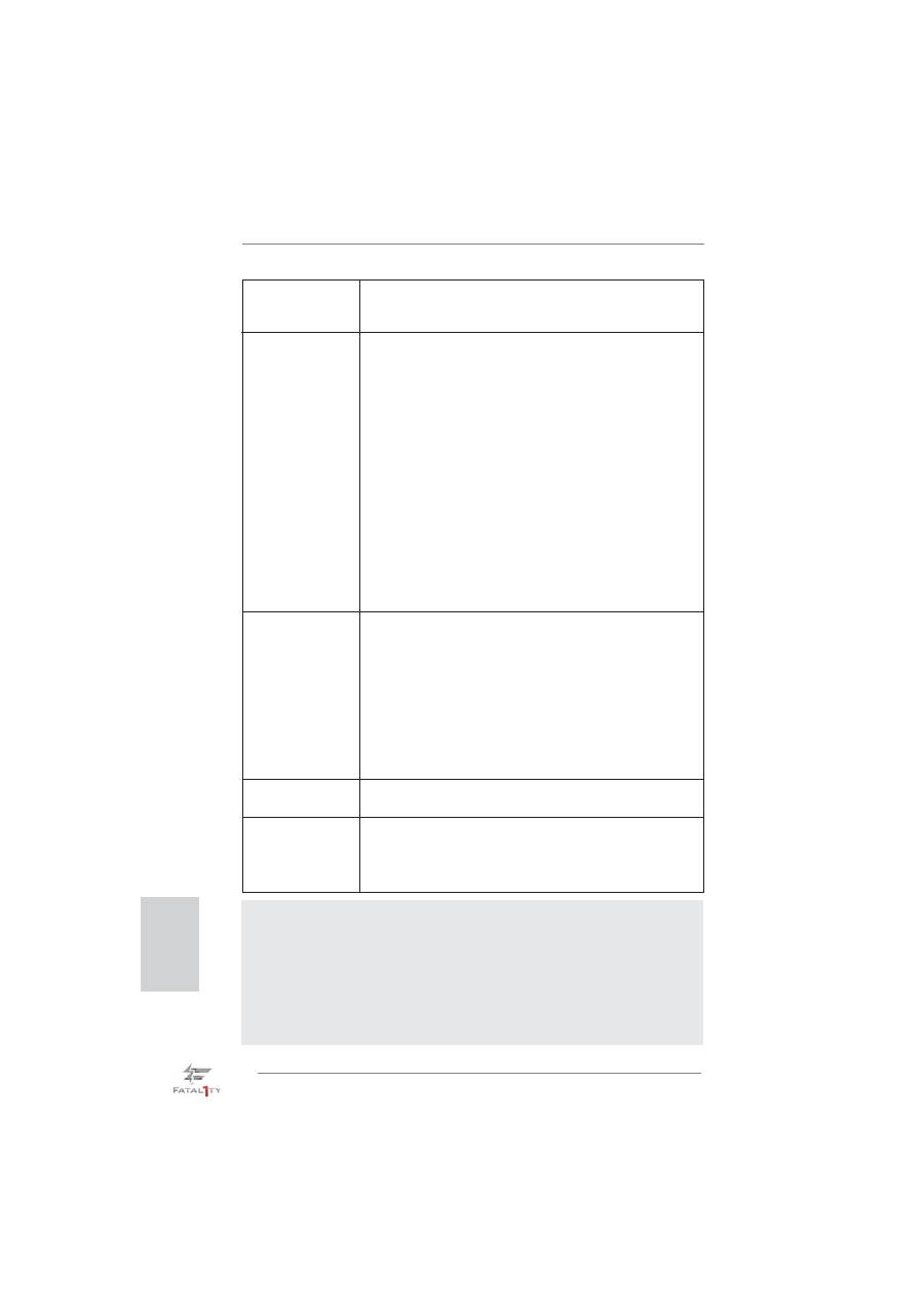
Reset Switch
Reset Switch is a smart switch,
(RSTBTN)
allowing users to quickly reset
(see p.4 No. 17)
the
system.
Clear CMOS Switch
Clear CMOS Switch is a smart
(CLRCBTN)
switch, allowing users to quickly
(see p.5 No. 17)
clear the CMOS values.
clr
CMOS
2.7 Smart Switches
The motherboard has three smart switches: power switch, reset switch and clear
CMOS switch, allowing users to quickly turn on/off or reset the sytem clear the
CMOS values.
Power Switch
Power Switch is a smart switch,
(PWRBTN)
allowing users to quickly turn
(see p.4 No. 16)
on/off the system.
Power
Reset
26
Fatal1ty P67 Performance Series Motherboard
English
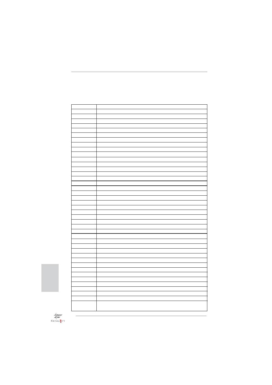
2.8 Dr. Debug
Dr. Debug is used to provide code information, which makes troubleshooting even
easier. Please see the diagrams below for reading the Dr. Debug codes.
Status Code
Description
0x00
Not used
0x01
Power on. Reset type detection (soft/hard)
0x02
AP initialization before microcode loading
0x03
North Bridge initialization before microcode loading
0x04
South Bridge initialization before microcode loading
0x05
OEM initialization before microcode loading
0x06
Microcode loading
0x07
AP initialization after microcode loading
0x08
North Bridge initialization after microcode loading
0x09
South Bridge initialization after microcode loading
0x0A
OEM initialization after microcode loading
0x0B
Cache initialization
0x0C – 0x0D
Reserved for future AMI SEC error codes
0x0E
Microcode not found
0x0F
Microcode not loaded
0x10
PEI Core is started
0x11
Pre-memory CPU initialization is started
0x12
Pre-memory CPU initialization (CPU module speci
fi
c)
0x13
Pre-memory CPU initialization (CPU module speci
fi
c)
0x14
Pre-memory CPU initialization (CPU module speci
fi
c)
0x15
Pre-memory North Bridge initialization is started
0x16
Pre-Memory North Bridge initialization (North Bridge module speci
fi
c)
0x17
Pre-Memory North Bridge initialization (North Bridge module speci
fi
c)
0x18
Pre-Memory North Bridge initialization (North Bridge module speci
fi
c)
0x19
Pre-memory South Bridge initialization is started
0x1A
Pre-memory South Bridge initialization (South Bridge module speci
fi
c)
0x1B
Pre-memory South Bridge initialization (South Bridge module speci
fi
c)
0x1C
Pre-memory South Bridge initialization (South Bridge module speci
fi
c)
0x1D – 0x2A
OEM pre-memory initialization codes
0x2B
Memory initialization. Serial Presence Detect (SPD) data reading
0x2C
Memory initialization. Memory presence detection
0x2D
Memory initialization. Programming memory timing information
0x2E
Memory initialization. Con
fi
guring memory
0x2F
Memory initialization (other)
0x30
Reserved for ASL (see ASL Status Codes section below)
0x31
Memory Installed
0x32
CPU post-memory initialization is started
0x33
CPU post-memory initialization. Cache initialization
0x34
CPU post-memory initialization. Application Processor(s) (AP) initialization
0x35
CPU post-memory initialization. Boot Strap Processor (BSP) selection
0x36
CPU post-memory initialization. System Management Mode (SMM)
initialization

Fatal1ty P67 Performance Series Motherboard
27
English
0x37
Post-Memory North Bridge initialization is started
0x38
Post-Memory North Bridge initialization (North Bridge module speci
fi
c)
0x39
Post-Memory North Bridge initialization (North Bridge module speci
fi
c)
0x3A
Post-Memory North Bridge initialization (North Bridge module speci
fi
c)
0x3B
Post-Memory South Bridge initialization is started
0x3C
Post-Memory South Bridge initialization (South Bridge module speci
fi
c)
0x3D
Post-Memory South Bridge initialization (South Bridge module speci
fi
c)
0x3E
Post-Memory South Bridge initialization (South Bridge module speci
fi
c)
0x3F-0x4E
OEM post memory initialization codes
0x4F
DXE IPL is started
0x50
Memory initialization error. Invalid memory type or incompatible memory
speed
0x51
Memory initialization error. SPD reading has failed
0x52
Memory initialization error. Invalid memory size or memory modules do not
match
0x53
Memory initialization error. No usable memory detected
0x54
Unspeci
fi
ed memory initialization error
0x55
Memory not installed
0x56
Invalid CPU type or Speed
0x57
CPU mismatch
0x58
CPU self test failed or possible CPU cache error
0x59
CPU micro-code is not found or micro-code update is failed
0x5A
Internal CPU error
0x5B
reset PPI is not available
0x5C-0x5F
Reserved for future AMI error codes
0xE0
S3 Resume is stared (S3 Resume PPI is called by the DXE IPL)
0xE1
S3 Boot Script execution
0xE2
Video repost
0xE3
OS S3 wake vector call
0xE4-0xE7
Reserved for future AMI progress codes
0xE8
S3 Resume Failed
0xE9
S3 Resume PPI not Found
0xEA
S3 Resume Boot Script Error
0xEB
S3 OS Wake Error
0xEC-0xEF
Reserved for future AMI error codes
0xF0
Recovery condition triggered by
fi
rmware (Auto recovery)
0xF1
Recovery condition triggered by user (Forced recovery)
0xF2
Recovery process started
0xF3
Recovery
fi
rmware image is found
0xF4
Recovery
fi
rmware image is loaded
0xF5-0xF7
Reserved for future AMI progress codes
0xF8
Recovery PPI is not available
0xF9
Recovery capsule is not found
0xFA
Invalid recovery capsule
0xFB – 0xFF
Reserved for future AMI error codes
0x60
DXE Core is started
0x61
NVRAM initialization

28
Fatal1ty P67 Performance Series Motherboard
English
0x62
Installation of the South Bridge Runtime Services
0x63
CPU DXE initialization is started
0x64
CPU DXE initialization (CPU module speci
fi
c)
0x65
CPU DXE initialization (CPU module speci
fi
c)
0x66
CPU DXE initialization (CPU module speci
fi
c)
0x67
CPU DXE initialization (CPU module speci
fi
c)
0x68
PCI host bridge initialization
0x69
North Bridge DXE initialization is started
0x6A
North Bridge DXE SMM initialization is started
0x6B
North Bridge DXE initialization (North Bridge module speci
fi
c)
0x6C
North Bridge DXE initialization (North Bridge module speci
fi
c)
0x6D
North Bridge DXE initialization (North Bridge module speci
fi
c)
0x6E
North Bridge DXE initialization (North Bridge module speci
fi
c)
0x6F
North Bridge DXE initialization (North Bridge module speci
fi
c)
0x70
South Bridge DXE initialization is started
0x71
South Bridge DXE SMM initialization is started
0x72
South Bridge devices initialization
0x73
South Bridge DXE Initialization (South Bridge module speci
fi
c)
0x74
South Bridge DXE Initialization (South Bridge module speci
fi
c)
0x75
South Bridge DXE Initialization (South Bridge module speci
fi
c)
0x76
South Bridge DXE Initialization (South Bridge module speci
fi
c)
0x77
South Bridge DXE Initialization (South Bridge module speci
fi
c)
0x78
ACPI module initialization
0x79
CSM initialization
0x7A – 0x7F
Reserved for future AMI DXE codes
0x80 – 0x8F
OEM DXE initialization codes
0x90
Boot Device Selection (BDS) phase is started
0x91
Driver connecting is started
0x92
PCI Bus initialization is started
0x93
PCI Bus Hot Plug Controller Initialization
0x94
PCI Bus Enumeration
0x95
PCI Bus Request Resources
0x96
PCI Bus Assign Resources
0x97
Console Output devices connect
0x98
Console input devices connect
0x99
Super IO Initialization
0x9A
USB initialization is started
0x9B
USB Reset
0x9C
USB Detect
0x9D
USB Enable
0x9E – 0x9F
Reserved for future AMI codes
0xA0
IDE initialization is started
0xA1
IDE Reset
0xA2
IDE Detect
0xA3
IDE Enable
0xA4
SCSI initialization is started
0xA5
SCSI Reset

Fatal1ty P67 Performance Series Motherboard
29
English
0xA6
SCSI Detect
0xA7
SCSI Enable
0xA8
Setup Verifying Password
0xA9
Start of Setup
0xAA
Reserved for ASL (see ASL Status Codes section below)
0xAB
Setup Input Wait
0xAC
Reserved for ASL (see ASL Status Codes section below)
0xAD
Ready To Boot event
0xAE
Legacy Boot event
0xAF
Exit Boot Services event
0xB0
Runtime Set Virtual Address MAP Begin
0xB1
Runtime Set Virtual Address MAP End
0xB2
Legacy Option ROM Initialization
0xB3
System Reset
0xB4
USB hot plug
0xB5
PCI bus hot plug
0xB6
Clean-up of NVRAM
0xB7
Con
fi
guration Reset (reset of NVRAM settings)
0xB8 – 0xBF
Reserved for future AMI codes
0xC0 – 0xCF
OEM BDS initialization codes
0xD0
CPU initialization error
0xD1
North Bridge initialization error
0xD2
South Bridge initialization error
0xD3
Some of the Architectural Protocols are not available
0xD4
PCI resource allocation error. Out of Resources
0xD5
No Space for Legacy Option ROM
0xD6
No Console Output Devices are found
0xD7
No Console Input Devices are found
0xD8
Invalid password
0xD9
Error loading Boot Option (LoadImage returned error)
0xDA
Boot Option is failed (StartImage returned error)
0xDB
Flash update is failed
0xDC
Reset protocol is not available

30
Fatal1ty P67 Performance Series Motherboard
English
2.9 Driver Installation Guide
To install the drivers to your system, please insert the support CD to your optical
drive
fi
rst. Then, the drivers compatible to your system can be auto-detected and
listed on the support CD driver page. Please follow the order from up to bottom side
to install those required drivers. Therefore, the drivers you install can work properly.
2.10 Installing
Windows
®
7 / 7 64-bit / Vista
TM
/ Vista
TM
64-bit / XP / XP 64-bit With RAID Functions
If you want to install Windows
®
7 / 7 64-bit / Vista
TM
/ Vista
TM
64-bit / XP / XP 64-
bit on your SATA / SATAII / SATA3 HDDs with RAID functions, please refer to the
document at the following path in the Support CD for detailed procedures:
..\ RAID Installation Guide
2.11 Installing
Windows
®
7 / 7 64-bit / Vista
TM
/ Vista
TM
64-bit / XP
/ XP 64-bit Without RAID Functions
If you want to install Windows
®
7 / 7 64-bit / Vista
TM
/ Vista
TM
64-bit / XP / XP 64-
bit OS on your SATA / SATAII / SATA3 HDDs without RAID functions, please follow
below procedures according to the OS you install.
2.11.1 Installing Windows
®
XP / XP 64-bit Without RAID
Functions
If you want to install Windows
®
XP / XP 64-bit OS on your SATA / SATAII / SATA3
HDDs without RAID functions, please follow below steps.
STEP 1: Set up UEFI.
A. Enter UEFI SETUP UTILITY Advanced screen Storage Con
fi
guration.
B. Set the option “SATA Mode” to [IDE].
STEP 2: Install Windows
®
XP / XP 64-bit OS on your system.
Using SATA / SATAII / SATA3 HDDs without NCQ function

Fatal1ty P67 Performance Series Motherboard
31
English
2.11.2 Installing Windows
®
7 / 7 64-bit / Vista
TM
/ Vista
TM
64-bit
Without RAID Functions
If you want to install Windows
®
7 / 7 64-bit / Vista
TM
/ Vista
TM
64-bit OS on your SATA
/ SATAII / SATA3 HDDs without RAID functions, please follow below steps.
Using SATA / SATAII / SATA3 HDDs with NCQ function
STEP 1: Set Up UEFI.
A. Enter UEFI SETUP UTILITY Advanced screen Storage Con
fi
guration.
B. Set the option “SATA Mode” to [AHCI].
STEP 2: Install Windows
®
7 / 7 64-bit / Vista
TM
/ Vista
TM
64-bit OS on your
system.
Using SATA / SATAII / STA3 HDDs without NCQ function
STEP 1: Set up UEFI.
A. Enter UEFI SETUP UTILITY Advanced screen Storage Con
fi
guration.
B. Set the option “SATA Mode” to [IDE].
STEP 2: Install Windows
®
7 / 7 64-bit / Vista
TM
/ Vista
TM
64-bit OS on your
system.

32
Fatal1ty P67 Performance Series Motherboard
3. BIOS Information
The Flash Memory on the motherboard stores BIOS Setup Utility. When you start up
the computer, please press <F2> or <Del> during the Power-On-Self-Test (POST)
to enter BIOS Setup utility; otherwise, POST continues with its test routines. If you
wish to enter BIOS Setup after POST, please restart the system by pressing <Ctl>
+ <Alt> + <Delete>, or pressing the reset button on the system chassis. The BIOS
Setup program is designed to be user-friendly. It is a menu-driven program, which
allows you to scroll through its various sub-menus and to select among the prede-
termined choices. For the detailed information about BIOS Setup, please refer to the
User Manual (PDF
fi
le) contained in the Support CD.
4. Software Support CD information
This motherboard supports various Microsoft
®
Windows
®
operating systems: 7 / 7
64-bit / Vista
TM
/ Vista
TM
64-bit / XP / XP 64-bit. The Support CD that came with the
motherboard contains necessary drivers and useful utilities that will enhance moth-
erboard features. To begin using the Support CD, insert the CD into your CD-ROM
drive. It will display the Main Menu automatically if “AUTORUN” is enabled in your
computer. If the Main Menu does not appear automatically, locate and double-click
on the
fi
le “ASSETUP.EXE” from the BIN folder in the Support CD to display the
menus.
English
Fatal1ty P67 Performance Series Motherboard
33
1. Einführung
Wir danken Ihnen für den Kauf des
Fatal1ty P67 Performance Series
Mother-
board, ein zuverlässiges Produkt, welches unter den ständigen, strengen Qualitäts-
kontrollen von gefertigt wurde. Es bietet Ihnen exzellente Leistung und robustes De-
sign, gemäß der Verp
fl
ichtung von zu Qualität und Halbarkeit. Diese Schnellinstalla-
tionsanleitung führt in das Motherboard und die schrittweise Installation ein. Details
über das Motherboard
fi
nden Sie in der Bedienungsanleitung auf der Support-CD.
Da sich Motherboard-Spezi
fi
kationen und BIOS-Software verändern
können, kann der Inhalt dieses Handbuches ebenfalls jederzeit geändert
werden. Für den Fall, dass sich Änderungen an diesem Handbuch
ergeben, wird eine neue Version auf der Website, ohne weitere Ankündigung,
verfügbar sein. Die neuesten Gra
fi
kkarten und unterstützten CPUs sind auch
auf der Website aufgelistet.
Wenn Sie technische Unterstützung zu Ihrem Motherboard oder spezi
fi
sche
Informationen zu Ihrem Modell benötigen, besuchen Sie bitte unsere
Webseite.
1.1 Kartoninhalt
Fatal1ty P67 Performance Series
Motherboard
(ATX-Formfaktor: 30.5 cm x 24.4 cm; 12.0 Zoll x 9.6 Zoll)
Fatal1ty P67 Performance Series
Schnellinstallationsanleitung
Fatal1ty P67 Performance Series
Support-CD
Ein 80-adriges Ultra-ATA 66/100/133 IDE-Flachbandkabel
Ein Flachbandkabel für ein 3,5-Zoll-Diskettenlaufwerk
Vier Serial ATA (SATA) -Datenkabel (optional)
Ein Audiokabel (3,5 mm, Klinke) (optional)
Ein I/O Shield
Deutsch
Wir erinnert...
Zur besseren Leistung unter Windows
®
7 / 7, 64 Bit / Vista
TM
/ Vista
TM
64 Bit empfehlen wir, die Speicherkon
fi
guration im BIOS auf den AHCI-
Modus einzustellen. Hinweise zu den BIOS-Einstellungen
fi
nden Sie in
der Bedienungsanleitung auf der mitgelieferten CD.
34
Fatal1ty P67 Performance Series Motherboard
1.2 Spezifikationen
Plattform
- ATX-Formfaktor: 30.5 cm x 24.4 cm; 12.0 Zoll x 9.6 Zoll
- Alle Feste Kondensatordesign (100% in Japan gefertigte,
erstklassige leitfähige Polymer-Kondensatoren)
CPU
- Unterstützt Intel
®
Core
TM
(2te Generation) i7 / i5 / i3 im
LGA1155-Paket
- Erweitertes V8-Stromphasendesign
- Unterstützt Intel
®
Turbo Boost 2.0-Technologie
- Unterstützt freigegebene CPU der K-Serie
- Unterstützt Hyper-Threading-Technologie
(siehe
VORSICHT 1
)
Chipsatz
- Intel
®
P67
Speicher
- Unterstützung von Dual-Kanal-Speichertechnologie
(siehe
VORSICHT 2
)
- 4 x Steckplätze für DDR3
- Unterstützt DDR3 2133(OC)/1866(OC)/1600/1333/1066
non-ECC, ungepufferter Speicher (siehe
VORSICHT 3
)
- Max. Kapazität des Systemspeichers: 32GB
(siehe
VORSICHT 4
)
- Unterstützt Intel
®
Extreme Memory Pro
fi
le (XMP)
Erweiterungs-
- 1 x PCI Express 2.0 x16-Steckplatz
steckplätze
- 3 x PCI Express 2.0 x1-Steckplätze
- 3 x PCI -Steckplätze
Audio
-
7.1
CH HD Audio mit dem Inhalt Schutz
(Realtek ALC892 Audio Codec)
- Premium Blu-ray-Audio-Unterstützung
LAN
- PCIE x1 Gigabit LAN 10/100/1000 Mb/s
- Realtek RTL8111E
- Unterstützt Wake-On-LAN
- Unterstützt LAN-Kabelerkennung
- Unterstützt energieef
fi
zientes Ethernet 802.3az
E/A-Anschlüsse
I/O Panel
an der
- 1 x PS/2-Mausanschluss
Rückseite
- 1 x PS/2-Tastaturanschluss
- 1 x Koaxial-SPDIF-Ausgang
- 1 x optischer SPDIF-Ausgang
- 5 x Standard-USB 2.0-Anschlüsse
- 1 x Fatal1ty Mausanschluss (USB 2.0)
- 1 x eSATA3-Anschluss
- 2 x Standard-USB 3.0-Anschlüsse
Deutsch
Fatal1ty P67 Performance Series Motherboard
35
Deutsch
- 1 x RJ-45 LAN Port mit LED (ACT/LINK LED und SPEED
LED)
- 1 x CMOS löschen-Schalter mit LED
- HD Audiobuchse: Lautsprecher seitlich / Lautsprecher
hinten / Mitte/Bass / Audioeingang/ Lautsprecher vorne /
Mikrofon (siehe
VORSICHT 5
)
SATA3
- 2 x SATA 3-Anschlüsse (6,0 Gb/s); unterstützt RAID-
(RAID 0, RAID 1, RAID 10, RAID 5 und Intel Rapid
Storage), NCQ-, AHCI-und „Hot Plug“ (Hot-Plugging)-
Funktionen (SATA3_1-Anschluss wird mit dem
eSATA 3-Port geteilt)
USB3.0
- 2 x USB 3.0-Ports an der Rückseite durch Etron EJ168A,
unterstützt USB 1.0/2.0/3.0 mit bis zu 5 Gb/s
Anschlüsse
- 4 x SATA2 3,0 GB/s-Anschlüsse, unterstützen RAID-
(RAID 0, RAID 1, RAID 10, RAID 5 und Intel Rapid
Storage), NCQ-, AHCI-und „Hot Plug“ (Hot-Plugging)-
Funktionen
- 2 x SATA3 6,0 GB/s-Anschlüsse
- 1 x ATA133 IDE-Anschlüsse (Unterstützt bis 2 IDE-Geräte)
- 1 x FDD-Anschlüsse
- 1 x Infrarot-Modul-Header
- 1 x COM-Anschluss-Header
- 1 x HDMI_SPDIF-Anschluss
- 1 x Betriebs-LED-Header
-
CPU/Gehäuse/Stromlüfter-Anschluss
-
24-pin
ATX-Netz-Header
- 8-pin anschluss für 12V-ATX-Netzteil
- Anschluss für Audio auf der Gehäusevorderseite
- 3 x USB 2.0-Anschlüsse (Unterstützung 6 zusätzlicher
USB 2.0-Anschlüsse)
- 1 x Dr. Debug (Debug-LED mit 7 Segmenten)
Schnellschalter
- 1 x CMOS löschen-Schalter mit LED
- 1 x Netzschalter mit LED
- 1 x Rücksetzschalter (Reset) mit LED
BIOS
- 64Mb AMI BIOS
- AMIs Legal BIOS UEFI mit GUI-Unterstützung
- Unterstützung für “Plug and Play”
-
ACPI
1.1-Weckfunktionen
-
JumperFree-Übertaktungstechnologie
- SMBIOS 2.3.1
- DRAM, PCH, CPU PLL, VTT, VCSA Stromspannung
Multianpassung
36
Fatal1ty P67 Performance Series Motherboard
Support-CD
- Treiber, Dienstprogramme, Anti-Virus-Software (Testversion),
Software Suite (CyberLink DVD Suite und Creative Sound
Blaster X-Fi MB) (OEM- und Testversion)
Einzigartige
- F-Stream (siehe
VORSICHT 6
)
Eigenschaft
-
Sofortstart
- ASRock Instant Flash (siehe
VORSICHT 7
)
- ASRock APP Charger (siehe
VORSICHT 8
)
- SmartView (siehe
VORSICHT 9
)
- ASRock XFast USB (siehe
VORSICHT 10
)
-
ASRock
ein/aus-Wiedergabetechnologie
(siehe
VORSICHT 11
)
- Hybrid Booster:
- Schrittloser CPU-Frequenz-Kontrolle
(siehe
VORSICHT 12
)
- ASRock U-COP (siehe
VORSICHT 13
)
- Boot Failure Guard (B.F.G. – Systemstartfehlerschutz)
- Combo-Kühleroption (siehe
VORSICHT 14
)
- Gute Nacht-LED
Hardware Monitor
- Überwachung der CPU-Temperatur
-
Motherboardtemperaturerkennung
- Drehzahlmessung für CPU/Gehäuse/Stromlüfter
- Geräuscharmer CPU-/Gehäuselüfter (ermöglicht die au
tomatische Anpassung der Gehäuselüftergeschwindigkeit
durch CPU- Temperatur)
-
Mehrstu
fi
ge Geschwindigkeitsteuerung für CPU-/
Gehäuselüfter
- Spannungsüberwachung: +12V, +5V, +3.3V, Vcore
Betriebssysteme
- Unterstützt Microsoft
®
Windows
®
7 / 7 64-Bit / Vista
TM
/
Vista
TM
64-Bit / XP / XP 64-Bit
Zerti
fi
zierungen
- FCC, CE, WHQL
- Gemäß Ökodesign-Richtlinie (ErP/EuP) (Stromversorgung
gemäß Ökodesign-Richtlinie (ErP/EuP) erforderlich)
(siehe
VORSICHT 15
)
WARNUNG
Beachten Sie bitte, dass Overclocking, einschließlich der Einstellung im BIOS,
Anwenden der Untied Overclocking-Technologie oder Verwenden von Overclocking-
Werkzeugen von Dritten, mit einem gewissen Risiko behaftet ist. Overclocking kann
sich nachteilig auf die Stabilität Ihres Systems auswirken oder sogar Komponenten
und Geräte Ihres Systems beschädigen. Es geschieht dann auf eigene Gefahr und
auf Ihre Kosten. Wir übernehmen keine Verantwortung für mögliche Schäden, die
aufgrund von Overclocking verursacht wurden.
Deutsch

Fatal1ty P67 Performance Series Motherboard
37
Deutsch
VORSICHT!
1. Die Einstellung der “Hyper-Threading Technology”,
fi
nden Sie auf Seite
51 des auf der Support-CD enthaltenen Benutzerhandbuches beschrie-
ben.
2. Dieses Motherboard unterstützt Dual-Kanal-Speichertechnologie. Vor
Implementierung der Dual-Kanal-Speichertechnologie müssen Sie die
Installationsanleitung für die Speichermodule auf Seite 44 zwecks
richtiger Installation gelesen haben.
3. DDR3-Frequenzoptionen können je nach Prozessor variieren. Nur CPU
der K-Serie kann DDR3-Übertaktung auf 2133 und 1866 unterstützen.
4. Durch Betriebssystem-Einschränkungen kann die tatsächliche Speicher-
größe weniger als 4 GB betragen, da unter Windows
®
7 / Vista™ / XP
etwas Speicher zur Nutzung durch das System reserviert wird. Unter
Windows
®
OS mit 64-Bit-CPU besteht diese Einschränkung nicht.
5. Der Mikrofoneingang dieses Motherboards unterstützt Stereo- und Mono-
Modi. Der Audioausgang dieses Motherboards unterstützt 2-Kanal-,
4-Kanal-, 6-Kanal- und 8-Kanal-Modi. Stellen Sie die richtige Verbindung
anhand der Tabelle auf Seite 3 her.
6. F-Stream ist ein Alles-in-einem-Werkzeug zur Feineinstellung
verschiedener Systemfunktionen an einer benutzerfreundlichen
Schnittstelle; diese beinhaltet Hardware-Überwachung, Lüftersteuerung,
Übertaktung, OC DNA und IES. Über die Hardware-Überwachung
können Sie die Hauptsystemdaten einsehen. Die Lüftersteuerung zeigt
Ihnen zur Anpassung Lüftergeschwindigkeit und Temperatur an. Bei
der Übertaktung können Sie die CPU-Frequenz zur Erzielung optimaler
Systemleistung übertakten. OC DNA ermöglicht Ihnen die Speicherung
Ihrer OC-Einstellungen als Pro
fi
l, welches Sie mit Freunden teilen
können. Ihre Freunde können das OC-Pro
fi
l dann in ihrem System laden
und so die gleichen OC-Einstellungen erzielen. Per IES (Intelligent
Energy Saver) kann der Spannungsregulator bei Inaktivität der CPU-
Kerne die Anzahl an Ausgangsphasen zur Steigerung der Ef
fi
zienz
reduzieren – ohne die Rechenleistung zu beeinträchtigen.
7. ASRock Instant Flash ist ein im Flash-ROM eingebettetes BIOS-Flash-
Programm. Mithilfe dieses praktischen BIOS-Aktualisierungswerkzeugs
können Sie das System-BIOS aktualisieren, ohne dafür zuerst Betriebs-
systeme wie MS-DOS oder Windows
®
aufrufen zu müssen. Mit diesem
Programm bekommen Sie durch Drücken der <F6>-Taste
während des POST-Vorgangs oder durch Drücken der <F2>-Taste im
BIOS-Setup-Menü Zugang zu ASRock Instant Flash. Sie brauchen dieses
Werkzeug einfach nur zu starten und die neue BIOS-Datei auf Ihrem
USB-Flash-Laufwerk, Diskettenlaufwerk oder der Festplatte zu
speichern, und schon können Sie Ihr BIOS mit nur wenigen Klickvorgän-
gen ohne Bereitstellung einer zusätzlichen Diskette oder eines ande-
ren komplizierten Flash-Programms aktualisieren. Achten Sie darauf,
dass das USB-Flash-Laufwerk oder die Festplatte das Dateisystem
FAT32/16/12 benutzen muss.

38
Fatal1ty P67 Performance Series Motherboard
8. Wenn Sie nach einer schnelleren, weniger eingeschränkten Möglichkeit
zur Au
fl
adung Ihrer Apple-Geräte (z. B. iPhone/iPad/iPod touch) suchen,
bietet ASRock Ihnen eine wunderbare Lösung – den ASRock APP
Charger. Installieren Sie einfach den ASRock APP Charger-Treiber;
dadurch lädt sich Ihr iPhone wesentlich schneller über einen Computer
auf – genaugenommen bis zu 40 % schneller als zuvor. Der ASRock APP
Charger ermöglicht Ihnen die schnelle Au
fl
adung mehrerer Apple-Geräte
gleichzeitig; der Ladevorgang wird sogar dann fortgesetzt, wenn der PC
den Ruhezustand (S1), Suspend to RAM-Modus (S3) oder Tiefschlafmo-
dus (S4) aufruft oder ausgeschaltet wird (S5). Nach der Installation des
APP Charger-Treibers können Sie im Handumdrehen das großartigste
Ladeerlebnis überhaupt genießen.
9. SmartView, eine neue Internetbrowserfunktion, ist eine intelligente IE-
Startseite, die meist besuchte Internetseiten, Ihren Browserverlauf,
Facebook-Freunde und Nachrichten in Echtzeit miteinander kombiniert:
In einer speziellen Ansicht, die das Internet noch angenehmer und aufre-
gender macht. ASRock-Motherboards werden exklusiv mit der Smart-
View-Software geliefert, die auch dafür sorgt, dass Sie immer mit Ihren
Freunden in Verbindung bleiben. Die SmartView-Funktionen können Sie
mit den Windows
®
-Betriebssystemen 7 / 7, 64 Bit / Vista
TM
/ Vista
TM
64 Bit
und dem Internet Explorer ab Version 8 nutzen.
10. ASRocks XFast USB dient der Steigerung der Leistungsfähigkeit Ihrer
USB-Speichergeräte. Die Leistung kann je nach Eigenschaften des
Gerätes variieren.
11. Durch die ASRock ein/aus-Wiedergabetechnologie können Sie großar-
tige Klangerlebnisse von portablen Audiogeräten, wie z. B. MP3-Playern
oder Mobiltelefonen, an Ihrem PC genießen – selbst wenn der PC ausge-
schaltet ist (oder sich im ACPI S5-Modus be
fi
ndet)! Dieses Motherboard
wird zudem mit einem kostenlosen Audiokabel (3,5 mm, Klinke) (optional)
geliefert, was eine IT-Umgebung von höchster Benutzerfreundlichkeit
gewährleistet.
12. Obwohl dieses Motherboard stufenlose Steuerung bietet, wird Over-
clocking nicht empfohlen. Frequenzen, die über den für den jeweiligen
Prozessor vorgesehenen liegen, können das System instabil werden
lassen oder die CPU beschädigen.
13. Wird eine Überhitzung der CPU registriert, führt das System einen au-
tomatischen Shutdown durch. Bevor Sie das System neu starten,
prüfen Sie bitte, ob der CPU-Lüfter am Motherboard richtig funktioniert,
und stecken Sie bitte den Stromkabelstecker aus und dann wieder ein.
Um die Wärmeableitung zu verbessern, bitte nicht vergessen, etwas
Wärmeleitpaste zwischen CPU und Kühlkörper zu sprühen.
14. Die Combo-Kühleroption bietet die
fl
exible Möglichkeit zur Aufnahme von
drei verschiedenen CPU-Kühlertypen, Socket LGA 775, LGA 1155 und LGA
1156. Beachten Sie bitte, dass nicht alle 775 und 1156 CPU-Lüfter verwen-
det werden können.
Deutsch

Fatal1ty P67 Performance Series Motherboard
39
Deutsch
15. EuP steht für Energy Using Product und kennzeichnet die Ökodesign-Richt-
linie, die von der Europäischen Gemeinschaft zur Festlegung des Ener-
gieverbrauchs von vollständigen Systemen in Kraft gesetzt wurde. Gemäß
dieser Ökodesign-Richtlinie (EuP) muss der gesamte Netzstromverbrauch
von vollständigen Systemen unter 1,00 Watt liegen,
wenn sie ausgeschaltet sind. Um dem EuP-Standard zu entsprechen,
sind ein EuP-fähiges Motherboard und eine EuP-fähige Stromversorgung
erforderlich. Gemäß einer Empfehlung von Intel muss eine EuP-fähige
Stromversorgung dem Standard entsprechen, was bedeutet, dass bei
einem Stromverbrauch von 100 mA die 5-Volt-Standby-Energieef
fi
zienz
höher als 50% sein sollte. Für die Wahl einer EuP-fähigen Stromversorgung
empfehlen wir Ihnen, weitere Details beim Hersteller der Stromversorgung
abzufragen.
40
Fatal1ty P67 Performance Series Motherboard
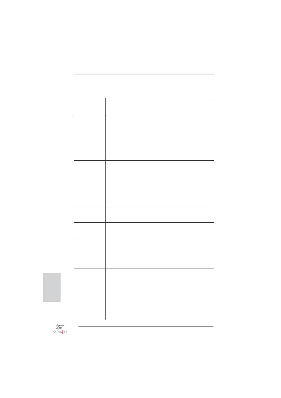
Contact Array
Socket Body
Load Lever
Load Plate
2. Installation
Sicherheitshinweise vor der Montage
Bitte nehmen Sie die folgende Sicherheitshinweise zur Kenntnis, bevor Sie das
Motherboard einbauen oder Veränderungen an den Einstellungen vornehmen.
1. Trennen Sie das System vom Stromnetz, bevor Sie eine ystemkomponente
berühren, da es sonst zu schweren Schäden am Motherboard oder den son-
stigen internen, bzw. externen omponenten kommen kann.
2. Um Schäden aufgrund von statischer Elektrizität zu vermeiden, das Mother-
board NIEMALS auf einen Teppich o.ä.legen. Denken Sie außerem daran,
immer ein geerdetes Armband zu tragen oder ein geerdetes Objekt aus Metall
zu berühren, bevor Sie mit Systemkomponenten hantieren.
3. Halten Sie Komponenten immer an den Rändern und vermeiden Sie Berüh-
rungen mit den ICs.
4. Wenn Sie Komponenten ausbauen, legen Sie sie immer auf eine antistatische
Unterlage, oder zurück in die Tüte, mit der die Komponente geliefert wurde.
5. Wenn Sie das Motherboard mit den Schrauben an dem Computergehäuse
befestigen, überziehen Sie bitte die Schrauben nicht! Das Motherboard kann
sonst beschädigt werden.
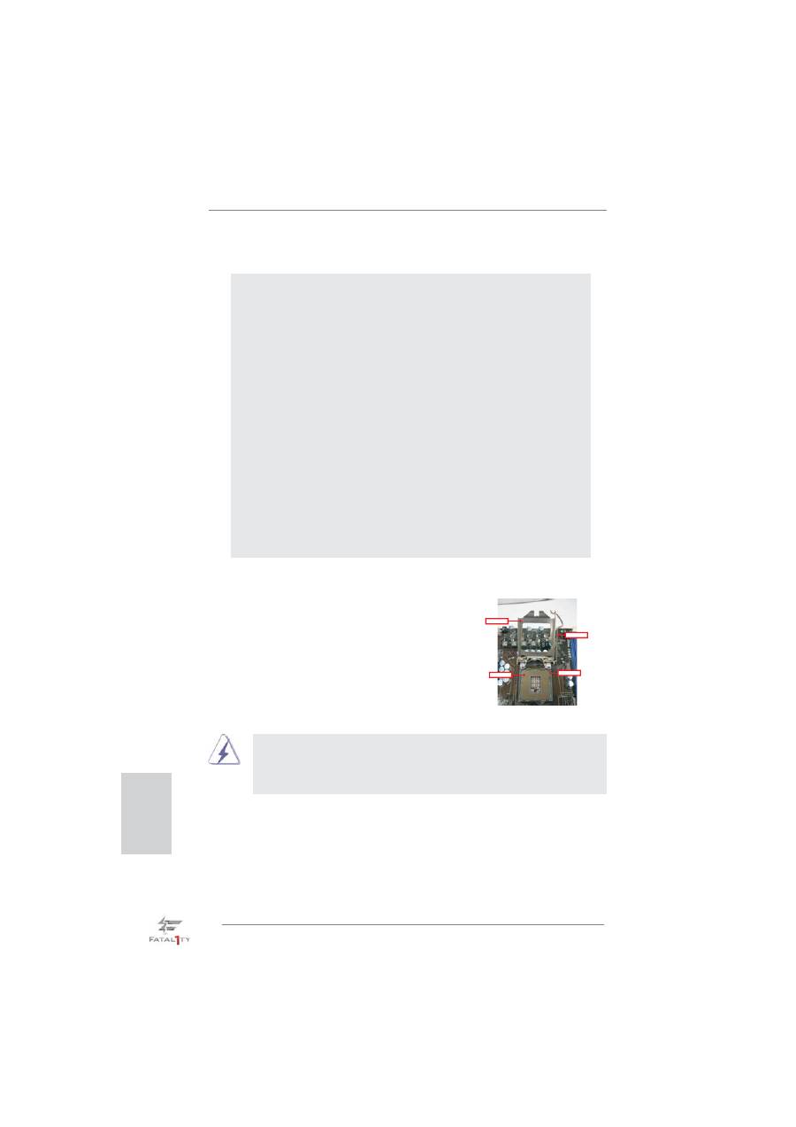
2.1 CPU Installation
Für die Installation des Intel 1155-Pin CPU
führen Sie bitte die folgenden Schritte durch.
1155-Pin Sockel Übersicht
(Ladeplatte)
(Kontaktreihe)
(Sockel)
Bevor Sie die 1155-Pin CPU in den Sockel sitzen, prüfen Sie bitte,
ob die CPU-Ober
fl
äche sauber ist und keine der Kontakte verbogen
sind. Setzen Sie die CPU nicht mit Gewalt in den Sockel, dies kann
die CPU schwer beschädigen.
Deutsch
