ASRock A75 Pro4-M – страница 2
Инструкция к Материнской Плате ASRock A75 Pro4-M
2.6 AMD Dual Graphics Operation Guide
This motherboard supports AMD Dual Graphics feature. AMD Dual Graphics brings
multi-GPU performance capabilities by enabling an AMD A75 FCH (Hudson-D3)
integrated graphics processor and a discrete graphics processor to operate
simultaneously with combined output to a single display for blisteringly-fast frame
®
rates. Currently, AMD Dual Graphics Technology is only supported with Windows
7
®
TM
OS, and is not available with Windows
Vista
/ XP OS.
What does an AMD Dual Graphics system include?
An AMD Dual Graphics system includes an AMD Radeon HD 65XX/64XX graphics
processor and a motherboard based on an AMD A75 FCH (Hudson-D3) integrated
®
chipset, all operating in a Windows
7 environment. Please refer to below PCI
Express graphics card support list for AMD Dual Graphics. For the future update of
more compatible PCI Express graphics cards, please visit AMD website for further
information.
Chipset Model Driver
AMD RADEON HD6670 ASUS DIS-PCIE2.1-ASUS-HDMI-EAH6670-DI-1GD3/1G-DDR3 8.86
AMD RADEON HD6570 MSI DIS-PCIE2.1-MSI-HDMI-R6570-MD1GD3-LP/1G-DDR3 8.86
AMD RADEON HD6450 MSI DIS-PCIE2.1-MSI-HDMI-R6450-MD1GD3-LP/1G-DDR3 8.86
Enjoy the benefit of AMD Dual Graphics
Step 1. Please keep the default UEFI setting of “Dual Graphics“ option on [Auto].
Step 2. Install one AMD RADEON HD6670 / 6570 / 6450 PCI Express graphics
card to PCIE1 slot (blue).
Step 3. Connect the monitor cable to the onboard VGA port. Please be noted that
the current VGA driver / VBIOS can allow Dual Graphics output from on-
board display only. For any future update, please refer to our website for
further information.
Step 4. Boot into OS. Please remove the AMD driver if you have any VGA driver
installed in your system.
Step 5. Install the onboard VGA driver from our support CD to your system for
both the onboard VGA and the discrete graphics card.
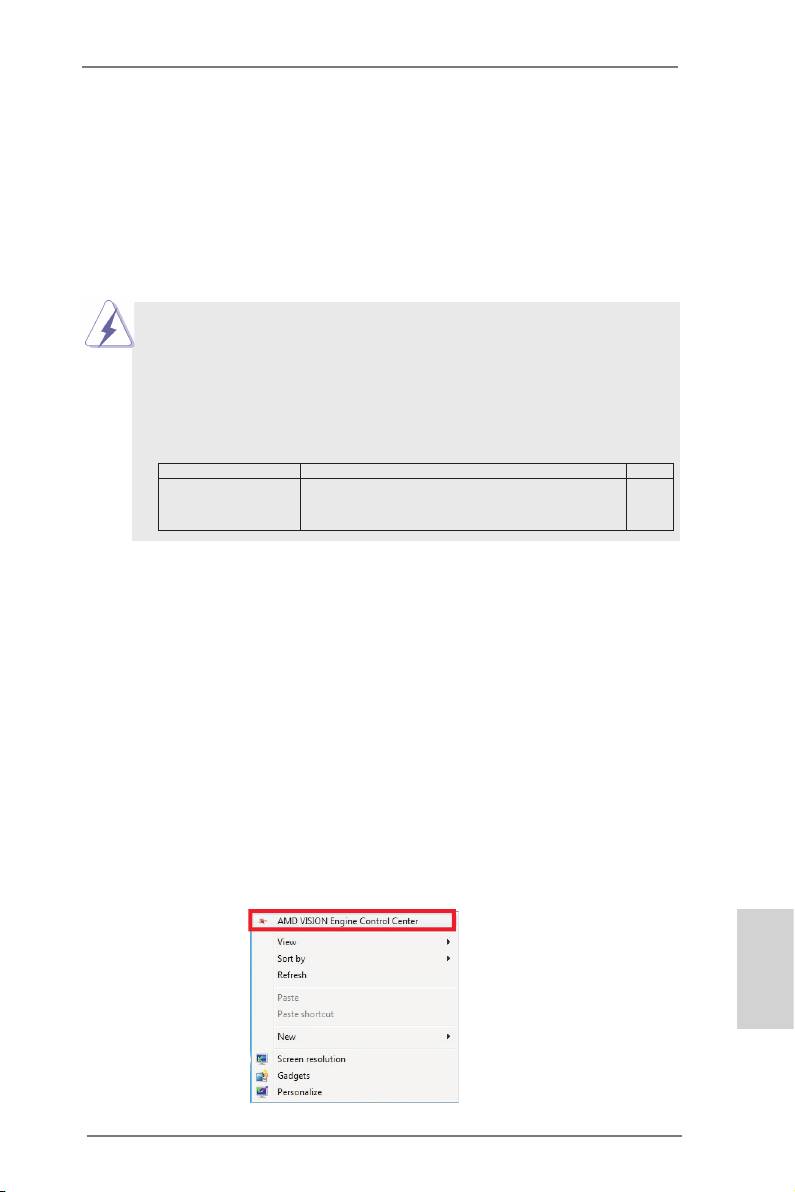
Step 6. Restart your computer. Right-click the desktop. Click “AMD VISION
Engine Control Center” to enter AMD VISION Engine Control Center.
English
21
ASRock A75 Pro4-M Motherboard
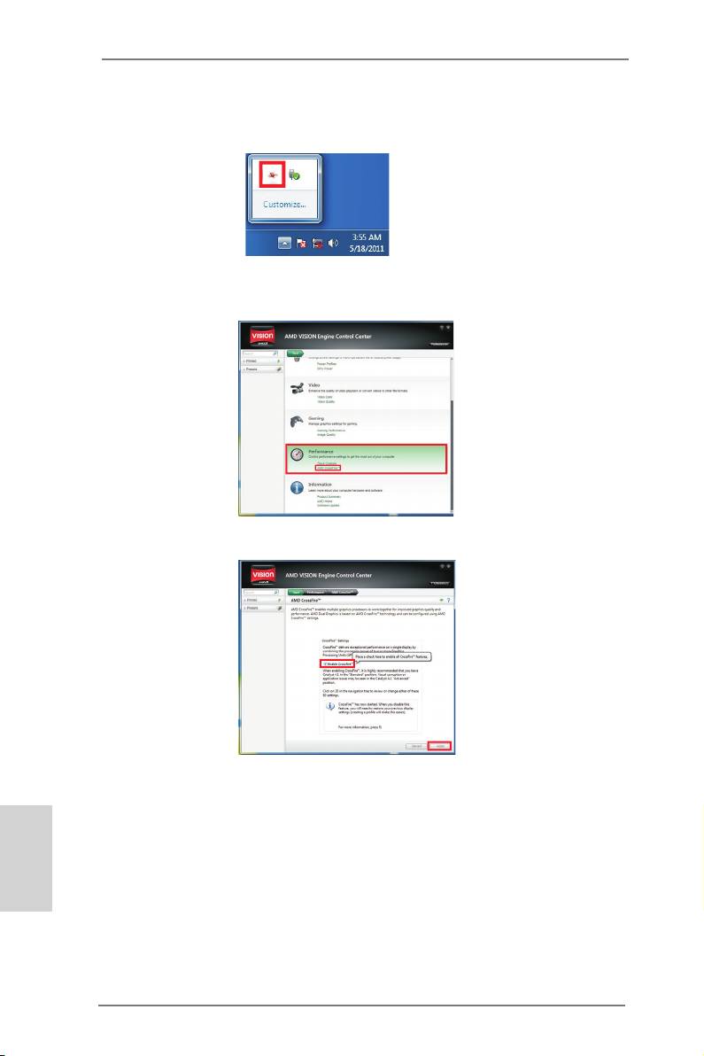
Step 7. You can also click “AMD VISION Engine Control Center” on your
®
Windows
taskbar to enter AMD VISION Engine Control Center.
AMD VISION Engine Control Center
Step 8. In AMD VISION Engine Control Center, please choose “Performance”.
TM
Click “AMD CrossFire
”.
TM
Step 9. Click “Enable CrossFire
” and click “Apply“ to save your change.
Step 10. Reboot your system. Then you can freely enjoy the benet of Dual
Graphics feature.
English
* Dual Graphics appearing here is a registered trademark of AMD Technologies Inc., and is
used only for identication or explanation and to the owners’ benet, without intent to infringe.
* For further information of AMD Dual Graphics technology, please check AMD website for up
dates and details.
22
ASRock A75 Pro4-M Motherboard
2.7 Dual Monitor and Surround Display Features
Dual Monitor Feature
This motherboard supports dual monitor feature. With the internal VGA output sup-
port (DVI-D, D-Sub and HDMI), you can easily enjoy the benets of dual monitor
feature without installing any add-on VGA card to this motherboard. This mother-
board also provides independent display controllers for DVI-D, D-Sub and HDMI to
support dual VGA output so that DVI-D, D-sub and HDMI can drive same or different
display contents.
To enable dual monitor feature, please follow the below steps:
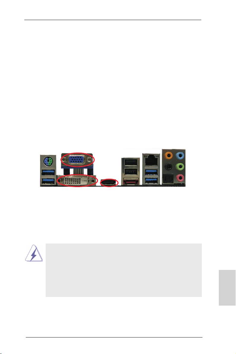
1. Connect DVI-D monitor cable to DVI-D port on the I/O panel, connect D-Sub
monitor cable to D-Sub port on the I/O panel, or connect HDMI monitor cable to
HDMI port on the I/O panel.
D-Sub port
DVI-D port
HDMI port
2. If you have installed onboard VGA driver from our support CD to your system
already, you can freely enjoy the benets of dual monitor function after your
system boots. If you haven’t installed onboard VGA driver yet, please install
onboard VGA driver from our support CD to your system and restart your
computer.
1. D-Sub, DVI-D and HDMI monitors cannot be enabled at the same
time. You can only choose the combination: DVI-D + HDMI, or HDMI
+ D-Sub.
2. When you playback HDCP-protected video from Blu-ray (BD) or
HD-DVD disc, the content will be displayed only in one of the two
monitors instead of both monitors.
3. To support Dual-link DVI monitor, please do not use D-Sub and HDMI
ports. Please connect the DVI monitor cable to the DVI port only.
English
23
ASRock A75 Pro4-M Motherboard

Surround Display Feature
This motherboard supports surround display upgrade. With the internal VGA output
support (DVI-D, D-Sub and HDMI) and external add-on PCI Express VGA cards,
you can easily enjoy the benets of surround display feature.
Please refer to the following steps to set up a surround display environment:
1. Install the PCI Express VGA cards on PCIE1 and PCIE2 slots. Please refer to
page 16 for proper expansion card installation procedures for details.
2. Connect DVI-D monitor cable to DVI-D port on the I/O panel, connect D-Sub
monitor cable to D-Sub port on the I/O panel, or connect HDMI monitor
cable to HDMI port on the I/O panel. Then connect other monitor cables to the
corresponding connectors of the add-on PCI Express VGA cards on PCIE1 and
PCIE4 slots.
3. Boot your system. Press <F2> or <Del> to enter UEFI setup. Enter “Share
Memory” option to adjust the memory capability to [32MB], [64MB], [128MB],
[256MB] or [512MB] to enable the function of D-sub. Please make sure that
the value you select is less than the total capability of the system memory. If you
do not adjust the UEFI setup, the default value of “Share Memory”, [Auto], will
disable D-Sub function when the add-on VGA card is inserted to this
motherboard.
4. Install the onboard VGA driver and the add-on PCI Express VGA card driver to
your system. If you have installed the drivers already, there is no need to install
them again.
5. Set up a multi-monitor display.
®
For Windows
XP / XP 64-bit OS:
Right click the desktop, choose “Properties”, and select the “Settings” tab
so that you can adjust the parameters of the multi-monitor according to
the steps below.
A. Click the “Identify” button to display a large number on each monitor.
B. Right-click the display icon in the Display Properties dialog that you
wish to be your primary monitor, and then select “Primary”. When
you use multiple monitors with your card, one monitor will always be
Primary, and all additional monitors will be designated as Secondary.
English
C. Select the display icon identied by the number 2.
D. Click “Extend my Windows desktop onto this monitor”.
E. Right-click the display icon and select “Attached”, if necessary.
F. Set the “Screen Resolution” and “Color Quality” as appropriate for the
second monitor. Click “Apply” or “OK” to apply these new values.
G. Repeat steps C through E for the diaplay icon identied by the number
one to six.
24
ASRock A75 Pro4-M Motherboard
®
TM
TM
For Windows
7 / 7 64-bit / Vista
/ Vista
64-bit OS:
Right click the desktop, choose “Personalize”, and select the “Display
Settings” tab so that you can adjust the parameters of the multi-monitor
according to the steps below.
A. Click the number ”2” icon.
B. Click the items “This is my main monitor” and “Extend the desktop onto
this monitor”.
C. Click “OK” to save your change.
D. Repeat steps A through C for the display icon identied by the number
three to six.
6. Use Surround Display. Click and drag the display icons to positions representing
the physical setup of your monitors that you would like to use. The placement
of display icons determines how you move items from one monitor to another.
HDCP Function
HDCP function is supported on this motherboard. To use HDCP
function with this motherboard, you need to adopt the monitor
that supports HDCP function as well. Therefore, you can enjoy
the superior display quality with high-denition HDCP
encryption contents. Please refer to below instruction for more
details about HDCP function.
What is HDCP?
HDCP stands for High-Bandwidth Digital Content Protection,
®
a specication developed by Intel
for protecting digital
entertainment content that uses the DVI interface. HDCP is a
copy protection scheme to eliminate the possibility of
intercepting digital data midstream between the video source,
or transmitter - such as a computer, DVD player or set-top box -
and the digital display, or receiver - such as a monitor, television
or projector. In other words, HDCP specication is designed to
protect the integrity of content as it is being transmitted.
Products compatible with the HDCP scheme such as DVD
players, satellite and cable HDTV set-top-boxes, as well as few
entertainment PCs requires a secure connection to a compliant
display. Due to the increase in manufacturers employing HDCP
English
in their equipment, it is highly recommended that the HDTV or
LCD monitor you purchase is compatible.
25
ASRock A75 Pro4-M Motherboard
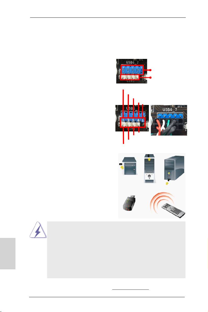
2.8 ASRock Smart Remote Installation Guide
ASRock Smart Remote is only used for ASRock motherboard with CIR header.
Please refer to below procedures for the quick installation and usage of ASRock
Smart Remote.
Step1. Find the CIR header located next
USB 2.0 header
to the USB 2.0 header on ASRock
(9-pin, blue)
motherboard.
CIR header
(4-pin, white)
USB_PWR
Step2. Connect the front USB cable to the
P-
USB 2.0 header (as below, pin 1-5)
P+
GND
and the CIR header. Please make
DUMMY
sure the wire assignments and the
pin assignments are matched
correctly.
GND
IRTX
IRRX
ATX+5VSB
Step3. Install Multi-Angle CIR Receiver to
the front USB port. If Multi-Angle
CIR Receiver cannot successfully
receive the infrared signals from
MCE Remote Controller, please try
to install it to the other front USB
port.
3 CIR sensors in different angles
1. Only one of the front USB port can support CIR function. When the
CIR function is enabled, the other port will remain USB function.
2. Multi-Angle CIR Receiver is used for front USB only. Please do not
English
use the rear USB bracket to connect it on the rear panel. Multi-Angle
CIR Receiver can receive the multi-direction infrared signals (top,
down and front), which is compatible with most of the chassis on the
market.
3. The Multi-Angle CIR Receiver does not support Hot-Plug function.
Please install it before you boot the system.
* ASRock Smart Remote is only supported by some of ASRock motherboards. Please refer to
ASRock website for the motherboard support list: http://www.asrock.com
26
ASRock A75 Pro4-M Motherboard
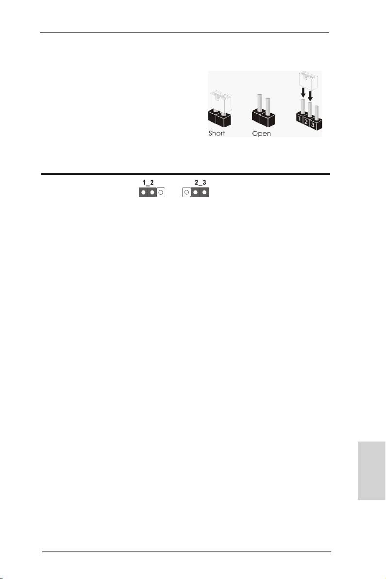
2.9 Jumpers Setup
The illustration shows how jumpers are
setup. When the jumper cap is placed on
pins, the jumper is “Short”. If no jumper cap
is placed on pins, the jumper is “Open”. The
illustration shows a 3-pin jumper whose
pin1 and pin2 are “Short” when jumper cap
is placed on these 2 pins.
Jumper Setting Description
Clear CMOS Jumper
(CLRCMOS1)
(see p.2, No. 11)
Clear CMOSDefault
Note: CLRCMOS1 allows you to clear the data in CMOS. To clear and reset the
system parameters to default setup, please turn off the computer and unplug
the power cord from the power supply. After waiting for 15 seconds, use a
jumper cap to short pin2 and pin3 on CLRCMOS1 for 5 seconds. However,
please do not clear the CMOS right after you update the BIOS. If you need
to clear the CMOS when you just nish updating the BIOS, you must boot
up the system rst, and then shut it down before you do the clear-CMOS ac-
tion. Please be noted that the password, date, time, user default prole, 1394
GUID and MAC address will be cleared only if the CMOS battery is removed.
English
27
ASRock A75 Pro4-M Motherboard
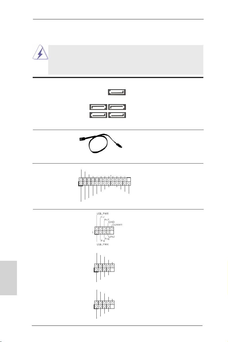
2.10 Onboard Headers and Connectors
Onboard headers and connectors are NOT jumpers. Do NOT place
jumper caps over these headers and connectors. Placing jumper caps
over the headers and connectors will cause permanent damage of the
motherboard!
Serial ATA3 Connectors These ve Serial ATA3
SATA3_5
(SATA3_1: see p.2, No. 15)
(SATA3) connectors support
(SATA3_2: see p.2, No. 16)
SATA data cables for internal
SATA3_2 SATA3_4
(SATA3_3: see p.2, No. 14)
storage devices. The current
(SATA3_4: see p.2, No. 13)
SATA3 interface allows up to
(SATA3_5: see p.2, No. 12)
6.0 Gb/s data transfer rate.
SATA3_1 SATA3_3
Serial ATA (SATA) Either end of the SATA data
Data Cable cable can be connected to the
(Optional)
SATA3 hard disk or the SATA3
connector on this motherboard.
Print Port Header This is an interface for print
AFD#
ERROR#
PINIT#
(25-pin LPT1)
port cable that allows
SLIN#
GND
(see p.2 No. 27)
convenient connection of printer
1
SPD7
devices.
SPD6
ACK#
SPD5
BUSY
SPD4
PE
SPD3
SLCT
SPD2
SPD1
SPD0
STB#
USB 2.0 Headers Besides two default USB 2.0
(9-pin USB6_7)
ports on the I/O panel, there
(see p.2 No. 21)
are three USB 2.0 headers on
this motherboard. Each USB 2.0
header can support two USB
2.0 ports.
U SB_PWR
(9-pin USB8_9)
P-9
P +9
(see p.2 No. 24)
GND
DUMMY
English
1
GND
P +8
P-8
U SB_PWR
U SB_PWR
(9-pin USB10_11)
P-11
P +11
(see p.2 No. 25)
GND
DUMMY
1
GND
P +10
P-10
U SB_PWR
28
ASRock A75 Pro4-M Motherboard
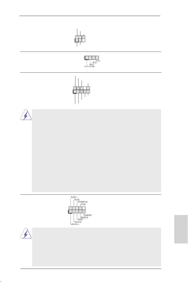
Infrared Module Header This header supports an
(5-pin IR1)
optional wireless transmitting
(see p.2 No. 26)
and receiving infrared module.
Consumer Infrared Module Header This header can be used to
(4-pin CIR1)
connect the remote
(see p.2 No. 23)
controller receiver.
Front Panel Audio Header This is an interface for the front
(9-pin HD_AUDIO1)
panel audio cable that allows
(see p.2 No. 30)
convenient connection and
control of audio devices.
English
29
ASRock A75 Pro4-M Motherboard
IRTX
+5VSB
DUMMY
1
GND
IRRX
GND
P RESENCE#
M IC_RET
OUT_RET
1
O UT2_L
J _SENSE
O UT2_R
M IC2_R
M IC2_L
1. High Denition Audio supports Jack Sensing, but the panel wire on
the chassis must support HDA to function correctly. Please follow the
instruction in our manual and chassis manual to install your system.
2. If you use AC’97 audio panel, please install it to the front panel audio
header as below:
A. Connect Mic_IN (MIC) to MIC2_L.
B. Connect Audio_R (RIN) to OUT2_R and Audio_L (LIN) to OUT2_L.
C. Connect Ground (GND) to Ground (GND).
D. MIC_RET and OUT_RET are for HD audio panel only. You don’t
need to connect them for AC’97 audio panel.
E. To activate the front mic.
®
For Windows
XP / XP 64-bit OS:
Select “Mixer”. Select “Recorder”. Then click “FrontMic”.
®
TM
TM
For Windows
7 / 7 64-bit / Vista
/ Vista
64-bit OS:
Go to the "FrontMic" Tab in the Realtek Control panel. Adjust
“Recording Volume”.
System Panel Header This header accommodates
(9-pin PANEL1)
several system front panel
(see p.2 No. 17)
functions.
Connect the power switch, reset switch and system status indicator
on the chassis to this header according to the pin assignments below.
Note the positive and negative pins before connecting the cables.
PWRBTN (Power Switch):
Connect to the power switch on the chassis front panel. You may con-
gure the way to turn off your system using the power switch.
RESET (Reset Switch):
Connect to the reset switch on the chassis front panel. Press the reset
switch to restart the computer if the computer freezes and fails to per-
form a normal restart.
PLED (System Power LED):
Connect to the power status indicator on the chassis front panel. The
LED is on when the system is operating. The LED keeps blinking
when the sys-tem is in S1 sleep state. The LED is off when the system
is in S3/S4 sleep state or powered off (S5).
HDLED (Hard Drive Activity LED):
Connect to the hard drive activity LED on the chassis front panel. The
LED is on when the hard drive is reading or writing data.
The front panel design may differ by chassis. A front panel module
mainly consists of power switch, reset switch, power LED, hard drive
activity LED, speaker and etc. When connecting your chassis front
panel module to this header, make sure the wire assignments and the
pin assign-ments are matched correctly.
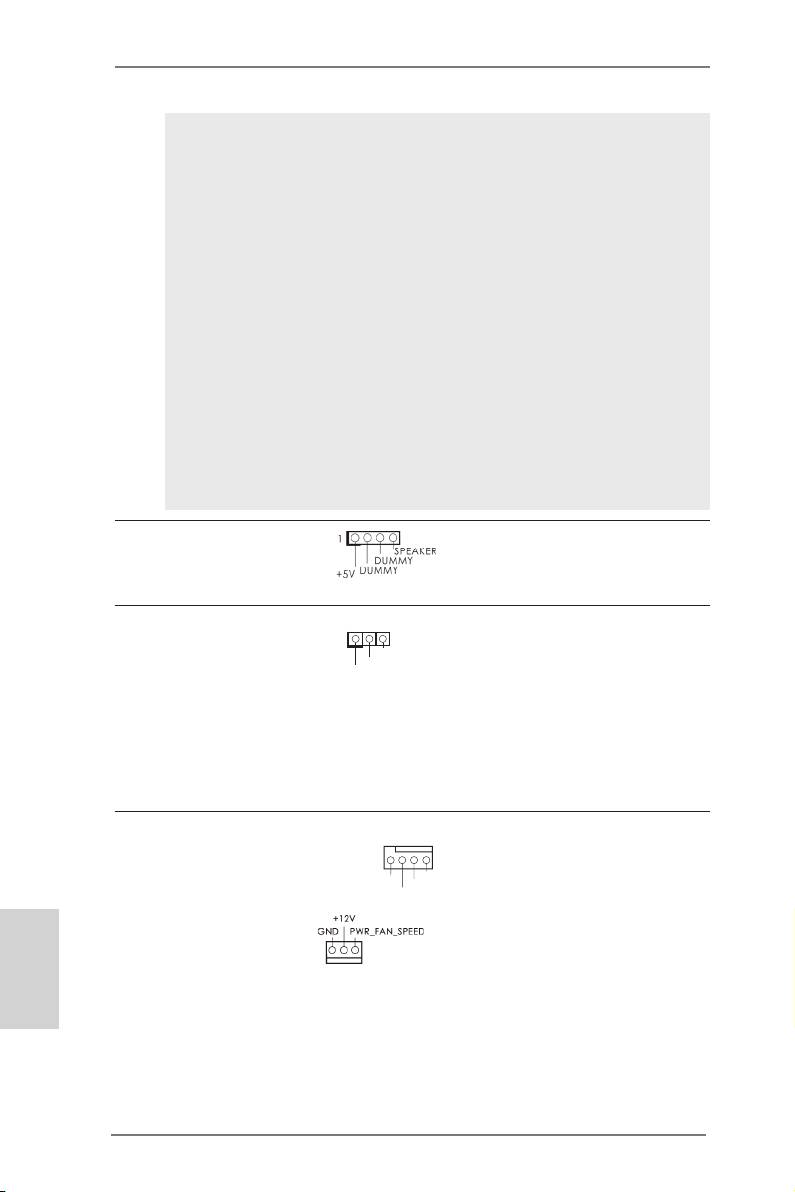
Chassis Speaker Header Please connect the chassis
(4-pin SPEAKER 1)
speaker to this header.
(see p.2 No. 18)
Power LED Header Please connect the chassis
1
(3-pin PLED1)
power LED to this header to
PLED-
PLED+
(see p.2 No. 20)
indicate system power status.
PLED+
The LED is on when the system
is operating. The LED keeps
blinking in S1 state. The LED is
off in S3/S4 state or S5 state
(power off).
Chassis and Power Fan Connectors Please connect the fan cables
(4-pin CHA_FAN1)
to the fan connectors and
(see p.2 No. 22)
match the black wire to the
GND
FAN_SPEED_CONTROL
+12V
CHA_FAN_SPEED
ground pin.
(3-pin PWR_FAN1)
English
(see p.2 No. 2)
30
ASRock A75 Pro4-M Motherboard
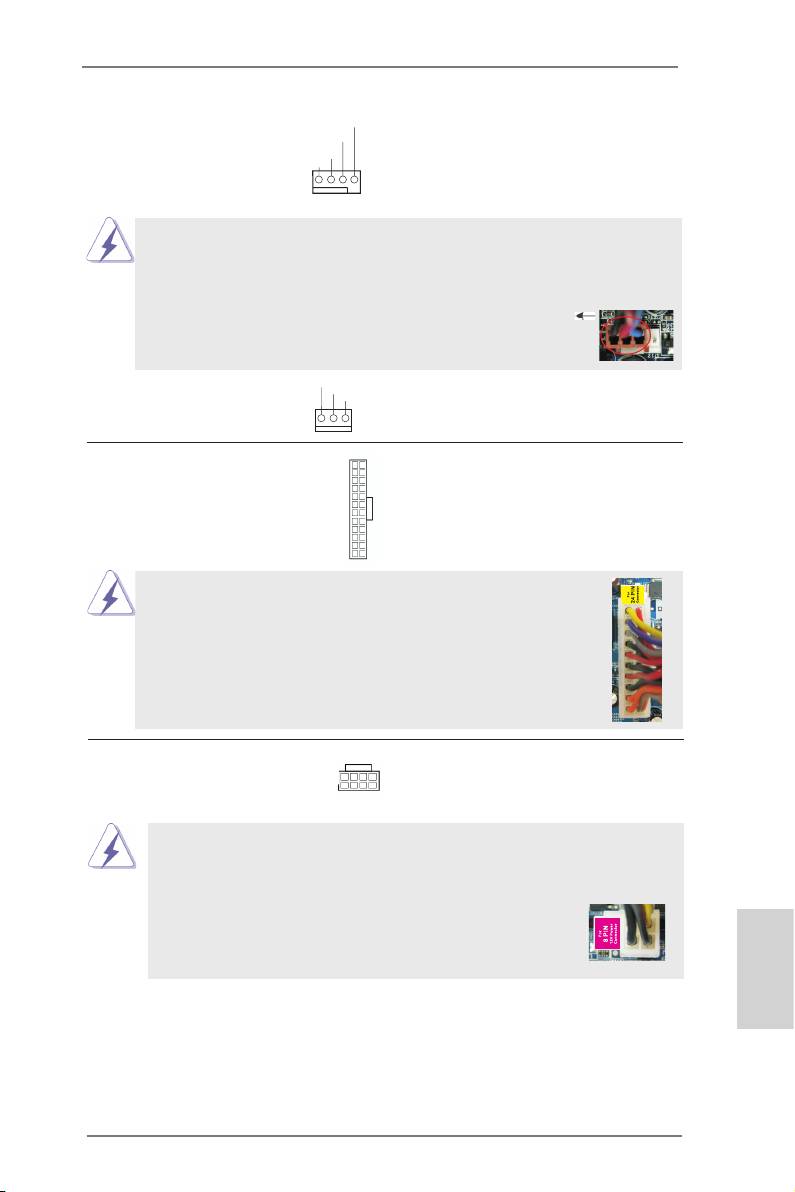
CPU Fan Connectors Please connect the CPU fan
FAN_S PEED_CONTROL
CPU_FAN_SPEED
(4-pin CPU_FAN1)
cable to the connector and
+ 12V
GND
(see p.2 No. 5)
match the black wire to the
ground pin.
1 2 3 4
Though this motherboard provides 4-Pin CPU fan (Quiet Fan) support, the 3-Pin
CPU fan still can work successfully even without the fan speed control function.
If you plan to connect the 3-Pin CPU fan to the CPU fan connector on this
motherboard, please connect it to Pin 1-3.
Pin 1-3 Connected
3-Pin Fan Installation
GND
(3-pin CPU_FAN2)
+ 12V
CPU_FAN_SPEED
(see p.2 No. 6)
ATX Power Connector Please connect an ATX power
12
24
(24-pin ATXPWR1)
supply to this connector.
(see p.2 No. 9)
1
13
Though this motherboard provides 24-pin ATX power connector,
12
24
it can still work if you adopt a traditional 20-pin ATX power supply.
To use the 20-pin ATX power supply, please plug your power
supply along with Pin 1 and Pin 13.
20-Pin ATX Power Supply Installation
1
13
ATX 12V Power Connector Please connect an ATX 12V
8 5
(8-pin ATX12V1)
power supply to this connector.
4 1
(see p.2 No. 1)
Though this motherboard provides 8-pin ATX 12V power connector, it can still work
if you adopt a traditional 4-pin ATX 12V power supply. To use the 4-pin ATX power
supply, please plug your power supply along with Pin 1 and Pin 5.
8 5
4-Pin ATX 12V Power Supply Installation
4 1
English
31
ASRock A75 Pro4-M Motherboard
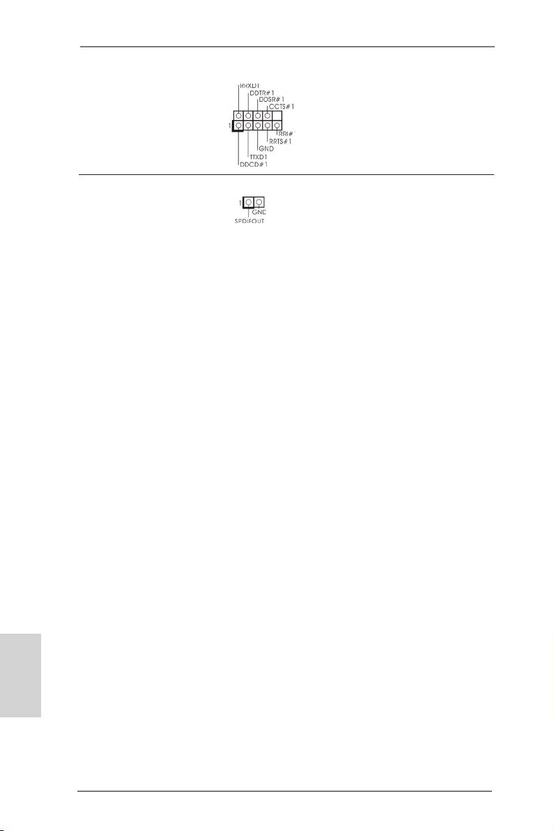
Serial port Header This COM1 header supports a
(9-pin COM1)
serial port module.
(see p.2 No.28)
HDMI_SPDIF Header HDMI_SPDIF header, providing
(2-pin HDMI_SPDIF1)
SPDIF audio output to HDMI
(
see p.2 No. 29)
VGA card, allows the system to
connect HDMI Digital TV/
projector/LCD devices. Please
connect the HDMI_SPDIF
connector of HDMI VGA card to
this header.
English
32
ASRock A75 Pro4-M Motherboard

2.11 Driver Installation Guide
To install the drivers to your system, please insert the support CD to your optical
drive rst. Then, the drivers compatible to your system can be auto-detected and
listed on the support CD driver page. Please follow the order from up to bottom side
to install those required drivers. Therefore, the drivers you install can work properly.
®
TM
TM
2.12 Installing Windows
7 / 7 64-bit / Vista
/ Vista
64-bit / XP /
XP 64-bit With RAID Functions
®
TM
TM
If you want to install Windows
7 / 7 64-bit / Vista
/ Vista
64-bit / XP / XP 64-
bit on your SATA3 HDDs with RAID functions, please refer to the document at the
following path in the Support CD for detailed procedures:
..\ RAID Installation Guide
®
TM
TM
2.13 Installing Windows
7 / 7 64-bit / Vista
/ Vista
64-bit / XP /
XP 64-bit Without RAID Functions
®
TM
TM
If you want to install Windows
7 / 7 64-bit / Vista
/ Vista
64-bit / XP / XP 64-bit
OS on your SATA3 HDDs without RAID functions, please follow below procedures
according to the OS you install.
®
2.13.1 Installing Windows
XP / XP 64-bit Without RAID Functions
®
If you want to install Windows
XP / XP 64-bit on your SATA3 HDDs without RAID
functions, please follow below steps.
Using SATA3 HDDs without NCQ and Hot Plug functions (IDE mode)
STEP 1: Set up UEFI.
A. Enter UEFI SETUP UTILITY Advanced screen Storage
Conguration.
B. Set the “SATA Mode” option to [IDE].
®
STEP 2: Install Windows
XP / XP 64-bit OS on your system.
English
33
ASRock A75 Pro4-M Motherboard
®
TM
TM
2.13.2 Installing Windows
7 / 7 64-bit / Vista
/ Vista
64-bit
Without RAID Functions
®
TM
TM
If you want to install Windows
7 / 7 64-bit / Vista
/ Vista
64-bit on your SATA3
HDDs without RAID functions, please follow below steps.
Using SATA3 HDDs without NCQ and Hot Plug functions (IDE mode)
STEP 1: Set up UEFI.
A. Enter UEFI SETUP UTILITY Advanced screen Storage
Conguration.
B. Set the “SATA Mode” option to [IDE].
®
TM
TM
STEP 2: Install Windows
7 / 7 64-bit / Vista
/ Vista
64-bit OS on your
system.
Using SATA3 HDDs with NCQ and Hot Plug functions (AHCI mode)
STEP 1: Set up UEFI.
A. Enter UEFI SETUP UTILITY Advanced screen Storage
Conguration.
B. Set the “SATA Mode” option to [AHCI].
®
TM
TM
STEP 2: Install Windows
7 / 7 64-bit / Vista
/ Vista
64-bit OS on your
system.
English
34
ASRock A75 Pro4-M Motherboard

3. BIOS Information
The Flash Memory on the motherboard stores BIOS Setup Utility. When you start up
the computer, please press <F2> or <Del> during the Power-On-Self-Test (POST)
to enter BIOS Setup utility; otherwise, POST continues with its test routines. If you
wish to enter BIOS Setup after POST, please restart the system by pressing <Ctl>
+ <Alt> + <Delete>, or pressing the reset button on the system chassis. The BIOS
Setup program is designed to be user-friendly. It is a menu-driven program, which
allows you to scroll through its various sub-menus and to select among the prede-
termined choices. For the detailed information about BIOS Setup, please refer to the
User Manual (PDF le) contained in the Support CD.
4. Software Support CD information
®
®
This motherboard supports various Microsoft
Windows
operating systems: 7 / 7
TM
TM
64-bit / Vista
/ Vista
64-bit / XP SP3 / XP 64-bit. The Support CD that came with
the motherboard contains necessary drivers and useful utilities that will enhance
motherboard features. To begin using the Support CD, insert the CD into your CD-
ROM drive. It will display the Main Menu automatically if “AUTORUN” is enabled in
your computer. If the Main Menu does not appear automatically, locate and double-
click on the le “ASSETUP.EXE” from the BIN folder in the Support CD to display
the menus.
English
35
ASRock A75 Pro4-M Motherboard
1. Einführung
Wir danken Ihnen für den Kauf des ASRock A75 Pro4-M Motherboard, ein zuver-
lässiges Produkt, welches unter den ständigen, strengen Qualitätskontrollen von
ASRock gefertigt wurde. Es bietet Ihnen exzellente Leistung und robustes Design,
gemäß der Verpflichtung von ASRock zu Qualität und Halbarkeit. Diese Schnel-
linstallationsanleitung führt in das Motherboard und die schrittweise Installation
ein. Details über das Motherboard nden Sie in der Bedienungsanleitung auf der
Support-CD.
Da sich Motherboard-Spezikationen und BIOS-Software verändern
können, kann der Inhalt dieses Handbuches ebenfalls jederzeit geändert
werden. Für den Fall, dass sich Änderungen an diesem Handbuch
ergeben, wird eine neue Version auf der ASRock-Website, ohne weitere
Ankündigung, verfügbar sein. Die neuesten Grakkarten und unterstützten
CPUs sind auch auf der ASRock-Website aufgelistet.
ASRock-Website: http://www.asrock.com
Wenn Sie technische Unterstützung zu Ihrem Motherboard oder spezische
Informationen zu Ihrem Modell benötigen, besuchen Sie bitte unsere
Webseite:
www.asrock.com/support/index.asp
1.1 Kartoninhalt
ASRock A75 Pro4-M Motherboard
(Micro ATX-Formfaktor: 24.4 cm x 24.4 cm; 9.6 Zoll x 9.6 Zoll)
ASRock A75 Pro4-M Schnellinstallationsanleitung
ASRock A75 Pro4-M Support-CD
Zwei Serial ATA (SATA) -Datenkabel (optional)
Ein I/O Shield
ASRock erinnert...
®
TM
TM
Zur besseren Leistung unter Windows
7 / 7, 64 Bit / Vista
/ Vista
64 Bit empfehlen wir, die Speicherkonguration im BIOS auf den AHCI-
Modus einzustellen. Hinweise zu den BIOS-Einstellungen nden Sie in
der Bedienungsanleitung auf der mitgelieferten CD.
Deutsch
36
ASRock A75 Pro4-M Motherboard
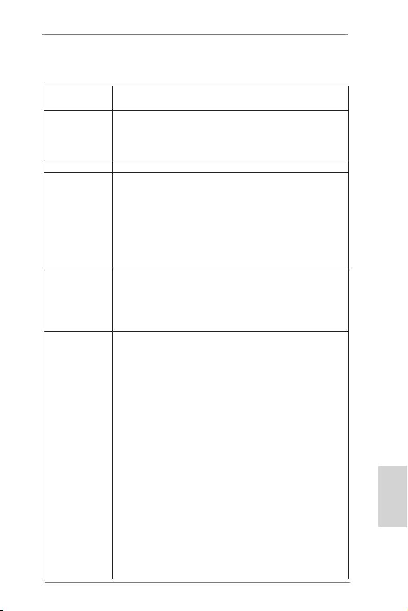
1.2 Spezifikationen
Plattform - Micro ATX-Formfaktor: 24.4 cm x 24.4 cm; 9.6 Zoll x 9.6 Zoll
- Alle Feste Kondensatordesign
CPU - Unterstützt Sockel-FM1-100-W-Prozessoren
- V4 + 1-Stromphasendesign
TM
- Unterstützt Cool ‘n’ Quiet
-Technologie von AMD
- UMI-Link-GEN2
Chipsatz - AMD A75 FCH (Hudson-D3)
Speicher - Unterstützung von Dual-Kanal-Speichertechnologie
(siehe VORSICHT 1)
- 4 x Steckplätze für DDR3
- Unterstützt DDR3 2400+(OC)/1866/1600/1333/
1066/800 non-ECC, ungepufferter Speicher
(siehe VORSICHT 2)
- Max. Kapazität des Systemspeichers: 32GB
(siehe VORSICHT 3)
Erweiterungs- - 2 x PCI-Express-2.0-x16-Steckplätze
steckplätze (PCIE1: x16-Modus; PCIE2: x4-Modus)
- 2 x PCI -Steckplätze
TM
TM
- Unterstützt AMD Quad CrossFireX
, CrossFireX
und
duale Grakkarten
Onboard-VGA - AMD Radeon HD 65XX/64XX-Grak
- DirectX 11, Pixel Shader 5.0
- Maximal gemeinsam genutzter Speicher 512MB
(siehe VORSICHT 4)
- Drei VGA-Ausgangsoptionen: D-Sub, DVI-D sowie HDMI
(siehe VORSICHT 5)
- Unterstützt HDMI 1.4a mit einer maximalen Auösung von
1920 x 1200 bei 60 Hz
- Unterstützt Dual-link DVI mit einer maximalen Auösung von
2560 x 1600 bei 75 Hz
- Unterstützt D-Sub mit einer maximalen Auösung von
1920 x 1600 bei 60 Hz
- Unterstützt Auto Lip Sync, Deep Color (12bpc), xvYCC und
HBR (High Bit Rate-Audio) mit HDMI (kompatibler HDMI-
Bildschirm erforderlich) (siehe VORSICHT 6)
Deutsch
- Unterstützt stereoskopisches 3D per Blu-ray mit HDMI 1.4a
TM
- Unterstützt AMD Steady Video
: Neuartige Funktion der
Videonachbearbeitung für automatische Reduzierung von
Bildschwankungen bei Heim-/Online-Videos
- Unterstützt HDCP-Funktion mit DVI- und HDMI-Ports
37
ASRock A75 Pro4-M Motherboard
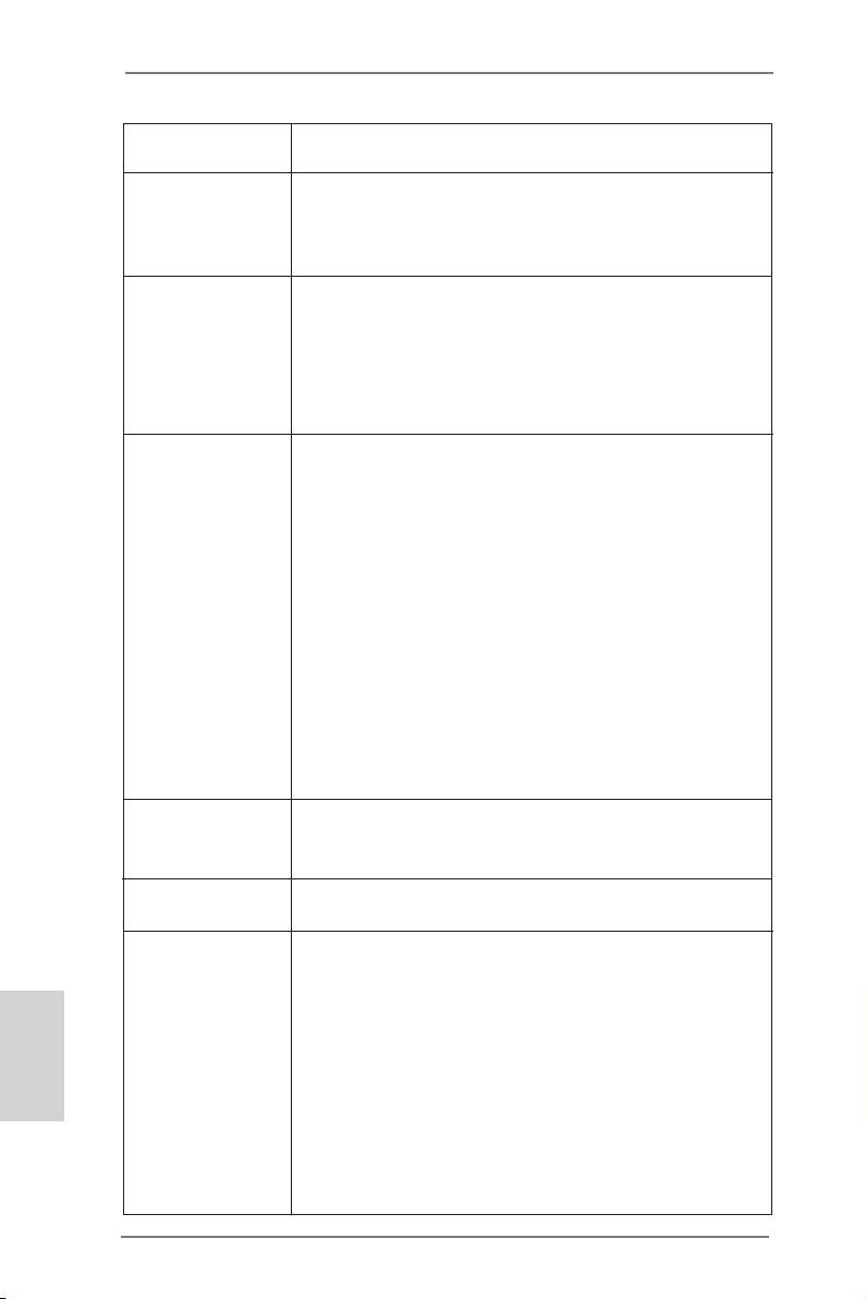
- Unterstutzt 1080p Blu-ray (BD) / HD-DVD-Wiedergabe mit
DVI- und HDMI-Ports
Audio - 7.1
CH HD Audio mit dem Inhalt Schutz
(Realtek ALC892 Audio Codec)
- Premium Blu-ray-Audio-Unterstützung
TM
- Unterstützt THX TruStudio
LAN - PCIE x1 Gigabit LAN 10/100/1000 Mb/s
- Realtek RTL8111E
- Unterstützt Wake-On-LAN
- Unterstützt LAN-Kabelerkennung
- Unterstützt energieefzientes Ethernet 802.3az
- Unterstützt PXE
E/A-Anschlüsse I/O Panel
an der - 1 x PS/2-Maus/Tastaturanschluss
Rückseite - 1 x D-Sub port
- 1 x DVI-D port
- 1 x HDMI port
- 1 x optischer SPDIF-Ausgang
- 2 x Standard-USB 2.0-Anschlüsse
- 1 x eSATA3-Anschluss
- 4 x Standard-USB 3.0-Anschlüsse
- 1 x RJ-45 LAN Port mit LED (ACT/LINK LED und SPEED
LED)
- HD Audiobuchse: Lautsprecher hinten / Mitte/Bass /
Audioeingang / Lautsprecher vorne / Mikrofon
(siehe VORSICHT 7)
SATA3 - 5 x SATA 3-Anschluss mit 6,0 Gb/s, unterstützt RAID-
(RAID 0, RAID 1 und RAID 10), NCQ-, AHCI- und „Hot
Plugging“-Funktionen
USB3.0 - 4 x USB 3.0-Ports, unterstützt USB 1.0/2.0/3.0 mit bis zu
5 Gb/s
Anschlüsse - 5 x SATA3 6,0 GB/s-Anschlüsse
- 1 x Infrarot-Modul-Header
- 1 x Consumer Infrarot-Modul-Header
Deutsch
- 1 x Druckerport-Anschlussleiste
- 1 x COM-Anschluss-Header
- 1 x HDMI_SPDIF-Anschluss
- 1 x Betriebs-LED-Header
- CPU/Gehäuse/Stromlüfter-Anschluss
- 24-pin ATX-Netz-Header
- 8-pin anschluss für 12V-ATX-Netzteil
- Anschluss für Audio auf der Gehäusevorderseite
38
ASRock A75 Pro4-M Motherboard
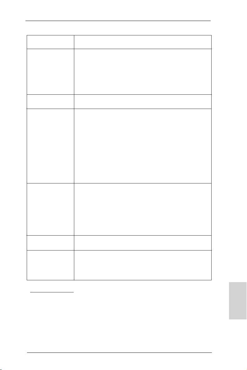
- 3 x USB 2.0-Anschlüsse (Unterstützung 6 zusätzlicher
USB 2.0-Anschlüsse)
BIOS - 32Mb AMIs Legal BIOS UEFI mit GUI-Unterstützung
- Unterstützung für “Plug and Play”
- ACPI 1.1-Weckfunktionen
- JumperFree-Modus
- SMBIOS 2.3.1
- DRAM, VDDP, VDDR, SB Stromspannung Multianpassung
Support-CD - Treiber, Dienstprogramme, Antivirussoftware
(Probeversion), CyberLink MediaEspresso 6.5-Testversion
Einzigartige - ASRock Extreme Tuning Utility (AXTU)
Eigenschaft (siehe VORSICHT 8)
- ASRock Sofortstart
- ASRock Instant Flash (siehe VORSICHT 9)
- ASRock APP Charger (siehe VORSICHT 10)
- ASRock XFast USB (siehe VORSICHT 11)
- ASRock ein/aus-Wiedergabetechnologie
(siehe VORSICHT 12)
- Hybrid Booster:
- ASRock U-COP (siehe VORSICHT 13)
Hardware Monitor - CPU-Temperatursensor
- Motherboardtemperaturerkennung
- Drehzahlmessung für CPU/Gehäuse/Stromlüfter
- Geräuscharmer CPU-/Gehäuselüfter
- Mehrstuge Geschwindigkeitsteuerung für CPU-/
Gehäuselüfter
- Spannungsüberwachung: +12V, +5V, +3.3V, Vcore
®
®
TM
Betriebssysteme - Unterstützt Microsoft
Windows
7 / 7 64-Bit / Vista
/
TM
Vista
64-Bit / XP SP3 / XP 64-Bit
Zertizierungen - FCC, CE, WHQL
- Gemäß Ökodesign-Richtlinie (ErP/EuP) (Stromversorgung
gemäß Ökodesign-Richtlinie (ErP/EuP) erforderlich)
(siehe VORSICHT 14)
* Für die ausführliche Produktinformation, besuchen Sie bitte unsere Website:
http://www.asrock.com
Deutsch
39
ASRock A75 Pro4-M Motherboard

WARNUNG
Beachten Sie bitte, dass Overclocking, einschließlich der Einstellung im BIOS, Anwenden
der Untied Overclocking-Technologie oder Verwenden von Overclocking-Werkzeugen von
Dritten, mit einem gewissen Risiko behaftet ist. Overclocking kann sich nachteilig auf die
Stabilität Ihres Systems auswirken oder sogar Komponenten und Geräte Ihres Systems
beschädigen. Es geschieht dann auf eigene Gefahr und auf Ihre Kosten. Wir übernehmen
keine Verantwortung für mögliche Schäden, die aufgrund von Overclocking verursacht wur-
den.
VORSICHT!
1.
Dieses Motherboard unterstützt Dual-Kanal-Speichertechnologie. Vor
Implementierung der Dual-Kanal-Speichertechnologie müssen Sie die
Installationsanleitung für die Speichermodule auf Seite 45 zwecks richtiger
Installation gelesen haben.
2. Ob die Speichergeschwindigkeit 2400/1866/1600 MHz unterstützt wird,
hängt von der von Ihnen eingesetzten CPU ab. Schauen Sie bitte auf un-
seren Internetseiten in der Liste mit unterstützten Speichermodulen nach,
wenn Sie DDR3 2400/1866/1600-Speichermodule einsetzen möchten.
ASRock-Internetseite: http://www.asrock.com
3. Durch Betriebssystem-Einschränkungen kann die tatsächliche Speicher-
®
TM
größe weniger als 4 GB betragen, da unter Windows
7 / Vista
/ XP
etwas Speicher zur Nutzung durch das System reserviert wird. Unter
®
Windows
OS mit 64-Bit-CPU besteht diese Einschränkung nicht.
4. Die Maximalspeichergröße ist von den Chipshändler deniert und umge-
tauscht. Bitte überprüfen Sie AMD website für die neuliche Information.
5. Sie können nur die Nutzung von zwei von drei Bildschirmen auswählen.
Die D-Sub-, DVI-D- und HDMI-Bildschirme können nicht gleichzeitig
aktiviert werden. Zudem kann der DVI-D-Port mit DVI-zu-HDMI-Adapter
dieselben Funktionen wie der HDMI-Port unterstützen.
®
6. xvYCC und Deep Color werden nur unter Windows
7 64-Bit / 7 unter-
stützt. Der Deep Color-Modus wird nur aktiviert, wenn der Bildschirm
®
TM
12bpc in EDID unterstützt. HBR wird unter Windows
7 64 Bit / 7 / Vista
TM
64 Bit / Vista
unterstützt.
7. Der Mikrofoneingang dieses Motherboards unterstützt Stereo- und Mono-
Modi. Der Audioausgang dieses Motherboards unterstützt 2-Kanal-,
4-Kanal-, 6-Kanal- und 8-Kanal-Modi. Stellen Sie die richtige Verbindung
anhand der Tabelle auf Seite 3 her.
Deutsch
8. ASRock Extreme Tuning Utility (AXTU) ist ein Alles-in-einem-
Werkzeug zur Feineinstellung verschiedener Systemfunktionen an
einer benutzerfreundlichen Schnittstelle; diese beinhaltet
HardwareÜberwachung, Lüftersteuerung und IES. Über die Hardware-
Überwachung können Sie die Hauptsystemdaten einsehen. Die
Lüftersteuerung zeigt Ihnen zur Anpassung Lüftergeschwindigkeit und
Temperatur an. Per IES (Intelligent Energy Saver) kann der Spannungs-
regulator bei Inaktivität der CPU-Kerne die Anzahl an Ausgangsphasen
40
ASRock A75 Pro4-M Motherboard
