ASRock 970 EXTREME4 – страница 3
Инструкция к Материнской Плате ASRock 970 EXTREME4

2.13 Serial ATA3 (SATA3) Hard Disks Installation
This motherboard adopts AMD SB950 chipset that supports Serial ATA3 (SATA3)
hard disks and RAID (RAID 0, RAID 1, RAID 0+1, JBOD and RAID 5) functions. You
may install SATA3 hard disks on this motherboard for internal storage devices. This
section will guide you to install the SATA3 hard disks.
STEP 1: Install the SATA3 hard disks into the drive bays of your chassis.
STEP 2: Connect the SATA power cable to the SATA3 hard disk.
STEP 3: Connect one end of the SATA data cable to the motherboard’s SATA3 con-
nector.
STEP 4: Connect the other end of the SATA data cable to the SATA3 hard disk.
2.14 Hot Plug and Hot Swap Functions for SATA3 HDDs
This motherboard supports Hot Plug and Hot Swap functions for SA TA3 in RAID
/ AHCI mode. AMD SB950 chipset provides hardware support for Advanced Host
controller Interface (AHCI), a new programming interface for SA TA host controllers
developed thru a joint industry effort.
NOTE
What is Hot Plug Function?
If the SATA3 HDDs are NOT set for RAID conf guration, it is called “Hot
Plug” for the action to insert and remove the SA TA3 HDDs while the
system is still power-on and in working condition.
However, please note that it cannot perform Hot Plug if the OS has
been installed into the SATA3 HDD.
What is Hot Swap Function?
If SATA3 HDDs are built as RAID 1 or RAID 5 then it is called “Hot
Swap” for the action to insert and remove the SA TA3 HDDs while the
system is still power-on and in working condition.
41

2.15 SATA3 HDD Hot Plug Feature and Operation Guide
This motherboard supports Hot Plug feature for SATA3 HDD in RAID / AHCI
mode. Please read below operation guide of Hot Plug feature carefully . Before you
process the SATA3 HDD Hot Plug, please check below cable accessories from the
motherboard gift box pack.
A. 7-pin SATA data cable
B. SATA power cable with SATA 15-pin power connector interface
A. SATA data cable (Red) B. SATA power cable
SATA 7-pin
The SATA 15-pin power
1x4-pin conventional
connector
connector (Black) connect
power connector (White)
to SATA3 HDD
connect to power supply
Caution
1. Without SATA 15-pin power connector interface, the SATA3 Hot Plug cannot be
processed.
2. Even some SATA3 HDDs provide both SATA 15-pin power connector and IDE
1x4-pin conventional power connector interfaces, the IDE 1x4-pin conventional
power connector interface is def nitely not able to support Hot Plug and will cause
the HDD damage and data loss.
Points of attention, before you process the Hot Plug:
1. Below operation procedure is designed only for our motherboard, which supports
SATA3 HDD Hot Plug.
* The SATA3 Hot Plug feature might not be supported by the chipset because of
its limitation, the SATA3 Hot Plug support information of our motherboard is
indicated in the product spec on our website: www.asrock.com
2. Make sure your SATA3 HDD can support Hot Plug function from your dealer or
HDD user manual. The SATA3 HDD, which cannot support Hot Plug function, will
be damaged under the Hot Plug operation.
3. Please make sure the SATA3 driver is installed into system properly. The latest
SATA3 driver is available on our support website: www.asrock.com
4. Make sure to use the SATA power cable & data cable, which are from our
motherboard package.
5. Please follow below instructions step by step to reduce the risk of HDD crash or
data loss.
42
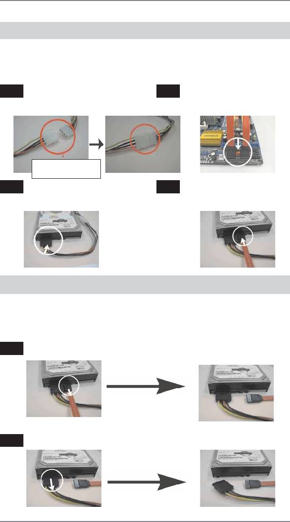
How to Hot Plug a SATA3 HDD:
Points of attention, before you process the Hot Plug:
Please do follow below instruction sequence to process the Hot Plug, improper
procedure will cause the SATA3 HDD damage and data loss.
Step 1
Please connect SATA power cable 1x4-pin
Step 2
Connect SATA data cable to
end (White) to the power supply 1x4-pin
the motherboard’s SATAII / SATA3
cable.
connector.
SATA power cable 1x4-pin
power connector (White)
Step 3
Connect SATA 15-pin power cable
Step 4
Connect SATA data cable to the
connector (Black) end to SATA3 HDD.
SATA3 HDD.
How to Hot Unplug a SATA3 HDD:
Points of attention, before you process the Hot Unplug:
Please do follow below instruction sequence to process the Hot Unplug, improper
procedure will cause the SATA3 HDD damage and data loss.
Step 1
Unplug SATA data cable from SATA3 HDD side.
Step 2
Unplug SATA 15-pin power cable connector (Black) from SATA3 HDD side.
43

2.16 Driver Installation Guide
To install the drivers to your system, please insert the support CD to your optical
drive f rst. Then, the drivers compatible to your system can be auto-detected and
listed on the support CD driver page. Please follow the order from up to bottom side
to install those required drivers. Therefore, the drivers you install can work properly.
®
TM
2.17 Installing Windows
7 / 7 64-bit / Vista
/
TM
Vista
64-bit / XP / XP 64-bit With RAID Functions
®
TM
TM
If you want to install Windows
7 / 7 64-bit / V ista
/ Vista
64-bit / XP / XP 64-bit
on a RAID disk composed of 2 or more SA TA3 HDDs with RAID functions, please
follow below procedures according to the OS you install.
®
2.17.1 Installing Windows
XP / XP 64-bit With RAID Functions
®
If you want to install Windows
XP / XP 64-bit on a RAID disk composed of 2 or
more SATA3 HDDs with RAID functions, please follow below steps.
STEP 1: Set up UEFI.
A. Enter UEFI SETUP UTILITY Advanced screen Storage Conf guration.
B. Set the “SATA Mode” option to [RAID].
STEP 2: Make a SATA3 Driver Diskette. (Please use USB fl oppy or fl oppy disk.)
A. Insert the ASRock Support CD into your optical drive to boot your system.
B. During POST at the beginning of system boot-up, press <F11> key, and
then a window for boot devices selection appears. Please select CD-ROM as
the boot device.
C. When you see the message on the screen, “Generate Serial ATA driver diskette
[YN]?”, press <Y>.
D. Then you will see these messages,
Please insert a diskette into the fl oppy drive.
WARNING! Formatting the fl oppy diskette will
lose ALL data in it!
Start to format and copy fi les [YN]?
Please insert a f oppy diskette into the f oppy drive, and press any key.
E. The system will start to format the f oppy diskette and copy SATA3 drivers into
the f oppy diskette.
44

STEP 3: Use “RAID Installation Guide” to set RAID confi guration.
Before you start to conf gure RAID function, you need to check the RAID installation
guide in the Support CD for proper con f guration. Please refer to the BIOS RAID
installation guide part of the document in the following path in the Support CD:
.. \ RAID Installation Guide
®
STEP 4: Install Windows
XP / XP 64-bit OS on your system.
®
After step 1, 2, 3, you can start to install Windows
XP / XP 64-bit OS on your
®
system. At the beginning of Windows
setup, press F6 to install a third-party RAID
driver. When prompted, insert the SA TA3 driver diskette containing the AMD RAID
driver. After reading the f oppy disk, the driver will be presented. Select the driver to
install according to the OS you install.
®
TM
2.17.2 Installing Windows
7 / 7 64-bit / Vista
/
TM
Vista
64-bit With RAID Functions
®
TM
TM
If you want to install Windows
7 / 7 64-bit / V ista
/ Vista
64-bit on a RAID disk
composed of 2 or more SATA3 HDDs with RAID functions, please follow below
steps.
STEP 1: Set up UEFI.
A. Enter UEFI SETUP UTILITY Advanced screen Storage Conf guration.
B. Set the “SATA Mode” option to [RAID].
STEP 2: Use “RAID Installation Guide” to set RAID confi guration.
Before you start to conf gure RAID function, you need to check the RAID installation
guide in the Support CD for proper con f guration. Please refer to the BIOS RAID
installation guide part of the document in the following path in the Support CD:
.. \ RAID Installation Guide
STEP 3: Make a SATA3 Driver Diskette. (Please use USB fl oppy or fl oppy disk.)
Make a SATA3 driver diskette by following section 2.17.1 step 2 on page 44.
®
TM
TM
STEP 4: Install Windows
7 / 7 64-bit / Vista
/ Vista
64-bit OS on your
system.
45

®
TM
2.18 Installing Windows
7 / 7 64-bit / Vista
/
TM
Vista
64-bit / XP / XP 64-bit Without RAID Functions
®
TM
TM
If you want to install Windows
7 / 7 64-bit / V ista
/ Vista
64-bit / XP / XP 64-bit
OS on your SA TA3 HDDs without RAID functions, please follow below procedures
according to the OS you install.
®
2.18.1 Installing Windows
XP / XP 64-bit Without RAID
Functions
®
If you want to install Windows
XP / XP 64-bit on your SA TA3 HDDs without RAID
functions, please follow below steps.
Using SATA3 HDDs with NCQ and Hot Plug functions (AHCI mode)
STEP 1: Set up UEFI.
A. Enter UEFI SETUP UTILITY Advanced screen Storage Conf guration.
B. Set the “SATA Mode” option to [AHCI].
STEP 2: Make a SATA3 Driver Diskette. (Please use USB fl oppy or fl oppy disk.)
Make a SATA3 driver diskette by following section 2.17.1 step 2 on page 44.
®
STEP 3: Install Windows
XP / XP 64-bit OS on your system.
®
You can start to install Windows
XP / XP 64-bit OS on your system. At the begin-
®
ning of Windows
setup, press F6 to install a third-party AHCI driver. When prompt-
ed, insert the SA TA3 driver diskette containing the AMD AHCI driver. After reading
the f oppy disk, the driver will be presented. Select the driver to install according to
the OS you install.
Using SATA3 HDDs without NCQ and Hot Plug functions (IDE mode)
STEP 1: Set up UEFI.
A. Enter UEFI SETUP UTILITY Advanced screen Storage Conf guration.
B. Set the “SATA Mode” option to [IDE].
®
STEP 2: Install Windows
XP / XP 64-bit OS on your system.
46

®
TM
2.18.2 Installing Windows
7 / 7 64-bit / Vista
/
TM
Vista
64-bit Without RAID Functions
®
TM
TM
If you want to install Windows
7 / 7 64-bit / V ista
/ Vista
64-bit on your SA TA3
HDDs without RAID functions, please follow below steps.
Using SATA3 HDDs with NCQ and Hot Plug functions (AHCI mode)
STEP 1: Set up UEFI.
A. Enter UEFI SETUP UTILITY Advanced screen Storage Conf guration.
B. Set the “SATA Mode” option to [AHCI].
®
TM
TM
STEP 2: Install Windows
7 / 7 64-bit / Vista
/ Vista
64-bit OS on your
system.
Using SATA3 HDDs without NCQ and Hot Plug functions (IDE mode)
STEP 1: Set up UEFI.
A. Enter UEFI SETUP UTILITY Advanced screen Storage Conf guration.
B. Set the “SATA Mode” option to [IDE].
®
TM
TM
STEP 2: Install Windows
7 / 7 64-bit / Vista
/ Vista
64-bit OS on your sys-
tem.
2.19 Untied Overclocking Technology
This motherboard supports Untied Overclocking Technology, which means during
overclocking, FSB enjoys better margin due to f xed PCI / PCIE buses. Before you
enable Untied Overclocking function, please enter “Overclock Mode” option of UEFI
setup to set the selection from [Auto] to [Manual]. Therefore, CPU FSB is untied
during overclocking, but PCI / PCIE buses are in the f xed mode so that FSB can
operate under a more stable overclocking environment.
Please refer to the warning on page 8 for the possible overclocking risk
before you apply Untied Overclocking Technology.
47

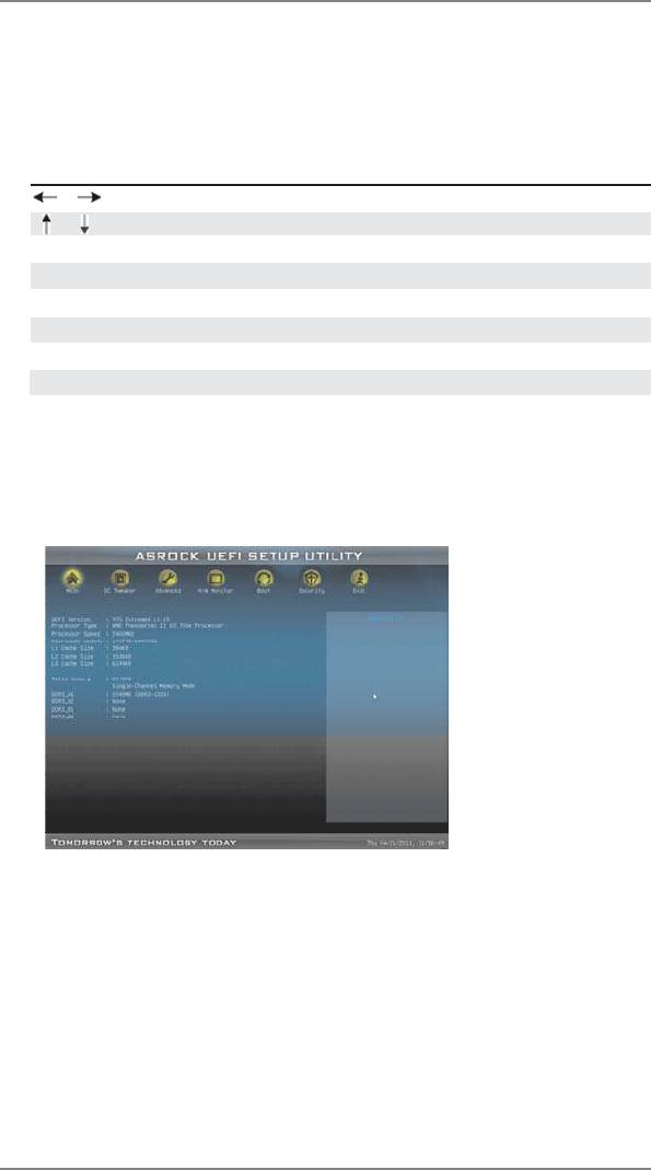
3. UEFI SETUP UTILITY
3.1 Introduction
This section explains how to use the UEFI SETUP UTILITY to conf gure your sys-
tem. The SPI Memory on the motherboard stores the UEFI SETUP UTILITY. You
may run the UEFI SETUP UTILITY when you start up the computer . Please press
<F2> or <Del>during the Power-On-Self-Test (POST) to enter the UEFI SETUP
UTILITY, otherwise, POST will continue with its test routines.
If you wish to enter the UEFI SETUP UTILITY after POST, restart the system by
pressing <Ctl> + <Alt> + <Delete>, or by pressing the reset button on the system
chassis. You may also restart by turning the system off and then back on.
Because the UEFI software is constantly being updated, the following
UEFI setup screens and descriptions are for reference purpose only ,
and they may not exactly match what you see on your screen.
3.1.1 UEFI Menu Bar
The top of the screen has a menu bar with the following selections:
Main To set up the system time/date information
OC Tweaker To set up overclocking features
Advanced To set up the advanced UEFI features
H/W Monitor To display current hardware status
Boot To set up the default system device to locate and load the
Operating System
Security To set up the security features
Exit To exit the current screen or the UEFI SETUP UTILITY
Use < > key or < > key to choose among the selections on the menu
bar, and then press <Enter> to get into the sub screen.
48
3.1.2 Navigation Keys
Please check the following table for the function description of each navigation
key.
Navigation Key(s) Function Description
/ Moves cursor left or right to select Screens
/ Moves cursor up or down to select items
+ / - To change option for the selected items
<Enter> To bring up the selected screen
<F1> To display the General Help Screen
<F9> To load optimal default values for all the settings
<F10> To save changes and exit the UEFI SETUP UTILITY
<ESC> To jump to the Exit Screen or exit the current screen
3.2 Main Screen
When you enter the UEFI SETUP UTILITY, the Main screen will appear and display
the system overview.
System Time [Hour:Minute:Second]
Use this item to specify the system time.
System Date [Day Month/Date/Year]
Use this item to specify the system date.
49

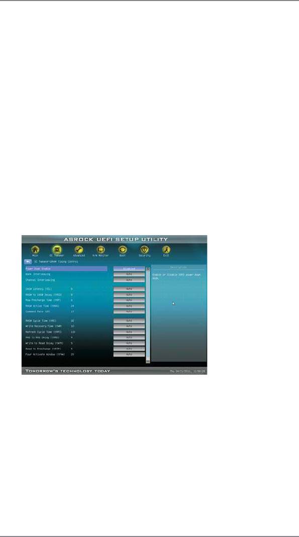
3.3 OC Tweaker Screen
In the OC Tweaker screen, you can set up overclocking features.
CPU Confi guration
Overclock Mode
Use this to select Overclock Mode. Configuration options: [Auto] and
[Manual]. The default value is [Auto].
Spread Spectrum
This item should always be [Auto] for better system stability.
ASRock UCC
ASRock UCC (Unlock CPU Core) feature simpli f es AMD CPU activation.
As long as a simple switch of the UEFI option “ASRock UCC”, you can
unlock the extra CPU core to enjoy an instant performance boost. When
UCC feature is enabled, the dual-core or triple-core CPU will boost to the
quad-core CPU, and some CPU, including quad-core CPU, can also in-
crease L3 cache size up to 6MB, which means you can enjoy the upgrade
CPU performance with a better price. Please be noted that UCC feature is
supported with AM3/AM3+ CPU only, and in addition, not every AM3/AM3+
CPU can support this function because some CPU’ s hidden core may be
malfunctioned.
CPU Active Core Control
This allows you to adjust CPU Active Core Control feature. The conf gura-
tion options depend on the CPU core you adopt. The default value is [Dis-
abled].
Processor Maximum Frequency
It will display Processor Maximum Frequency for reference.
North Bridge Maximum Frequency
It will display North Bridge Maximum Frequency for reference.
Processor Maximum Voltage
It will display Processor Maximum Voltage for reference.
50
Multiplier/Voltage Change
This item is set to [Auto] by default. If it is set to [Manual], you may adjust
the value of Processor Frequency and Processor Voltage. However, it is
recommended to keep the default value for system stability.
HT Bus Speed
This feature allows you selecting Hyper-T ransport bus speed. Con f gura-
tion options: [Auto], [200MHz] to [2000MHz].
HT Bus Width
This feature allows you selecting Hyper-Transport bus width. Conf guration
options: [Auto], [8 Bit] and [16 Bit].
DRAM Confi guration
DRAM Frequency
If [Auto] is selected, the motherboard will detect the memory module(s)
inserted and assigns appropriate frequency automatically.
DRAM Timing Control
Power Down Enable
Use this item to enable or disable DDR power down mode.
Bank Interleaving
Interleaving allows memory accesses to be spread out over banks on the
same node, or accross nodes, decreasing access contention.
Channel Interleaving
It allows you to enable Channel Memory Interleaving. Con f guration op-
tions: [Disabled], [Auto]. The default value is [Auto].
51

CAS# Latency (tCL)
Use this item to change CAS# Latency (tCL) Auto/Manual setting. The
default is [Auto].
RAS# to CAS# Delay (tRCD)
Use this item to change RAS# to CAS# Delay (tRCD) Auto/Manual setting.
The default is [Auto].
Row Precharge Time (tRP)
Use this item to change Row Precharge Time (tRP) Auto/Manual setting.
The default is [Auto].
RAS# Active Time (tRAS)
Use this item to change RAS# Active Time (tRAS) Auto/Manual setting.
The default is [Auto].
Command Rate (CR)
Use this item to change Command Rate (CR) Auto/Manual setting. Min:
1T. Max: 2T. The default is [Auto].
RAS# Cycle Time (tRC)
Use this item to change RAS# Cycle Time (tRC) Auto/Manual setting. The
default is [Auto].
Write Recovery Time (tWR)
Use this item to change Write Recovery Time (tWR) Auto/Manual setting.
The default is [Auto].
Refresh Cyle Time (tRFC)
Use this item to change Refresh Cyle Time (tRFC) Auto/Manual setting.
The default is [Auto].
RAS to RAS Delay (tRRD)
Use this item to change RAS to RAS Delay (tRRD) Auto/Manual setting.
The default is [Auto].
Write to Read Delay (tWTR)
Use this item to change Write to Read Delay (tWTR) Auto/Manual setting.
The default is [Auto].
Read to Precharge (tRTP)
Use this item to change Read to Precharge (tRTP) Auto/Manual setting.
The default is [Auto].
Four Activate Window (tFAW)
Use this item to change Four Activate Window (tFAW) Auto/Manual
setting. The default is [Auto].
Voltage Control
DRAM Voltage
Use this to select DRAM Voltage. The default value is [Auto].
52

NB Voltage
Use this to select NB Voltage. The default value is [Auto].
HT Voltage
Use this to select HT Voltage. The default value is [Auto].
CPU VDDA Voltage
Use this to select CPU VDDA Voltage. The default value is [Auto].
PCIE VDDA Voltage
Use this to select PCIE VDDA Voltage. The default value is [Auto].
SB Voltage
Use this to select SB Voltage. The default value is [Auto].
Would you like to save current setting user defaults?
In this option, you are allowed to load and save three user defaults
according to your own requirements.
53
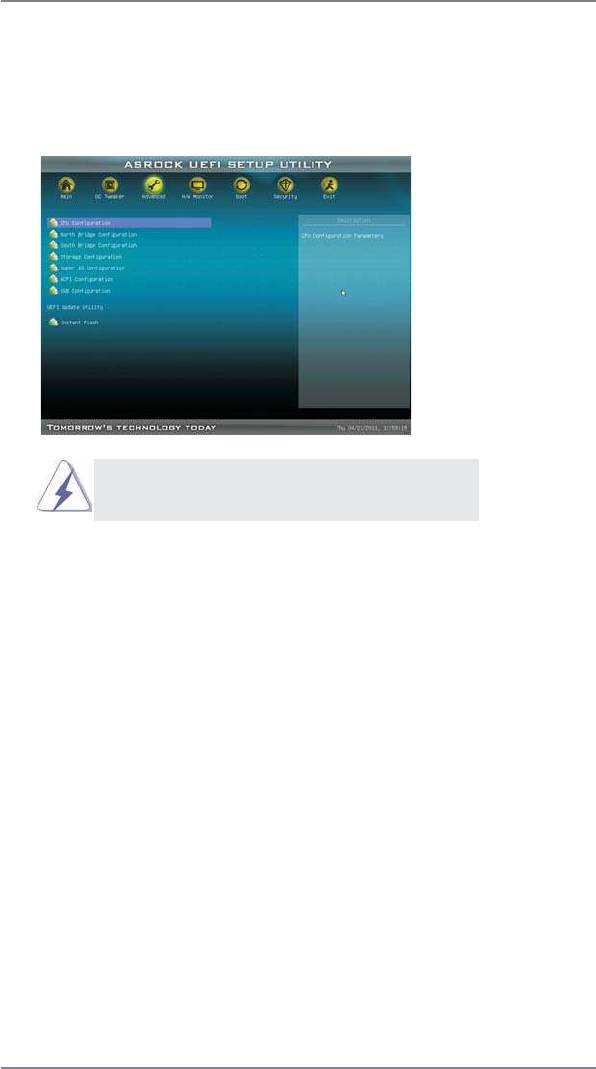
3.4 Advanced Screen
In this section, you may set the conf gurations for the following items: CPU Conf gu-
ration, Nouth Bridge Con f guration, South Bridge Con f guration, Storage Conf gura-
tion, Super IO Conf guration, ACPI Conf guration, and USB Conf guration.
Setting wrong values in this section may cause
the system to malfunction.
Instant Flash
Instant Flash is a UEFI f ash utility embedded in Flash ROM. This conve-
nient UEFI update tool allows you to update system UEFI without entering
®
operating systems f rst like MS-DOS or Windows
. Just launch this tool
and save the new UEFI f le to your USB f ash drive, f oppy disk or hard
drive, then you can update your UEFI only in a few clicks without prepar-
ing an additional f oppy diskette or other complicated f ash utility. Please
be noted that the USB f ash drive or hard drive must use FAT32/16/12 f le
system. If you execute Instant Flash utility , the utility will show the UEFI
f les and their respective information. Select the proper UEFI f le to update
your UEFI, and reboot your system after UEFI update process completes.
54

3.4.1 CPU Configuration
Cool ‘n’ Quiet
TM
Use this item to enable or disable AMD’s Cool ‘n’ Quiet
technology. The
default value is [Enabled]. Conf guration options: [Enabled] and [Disabled].
®
TM
If you install Windows
7 / Vista
and want to enable this function, please
set this item to [Enabled]. Please note that enabling this function may re-
duce CPU voltage and memory frequency , and lead to system stability or
compatibility issue with some memory modules or power supplies. Please
set this item to [Disable] if above issue occurs.
Secure Virtual Machine
When this option is set to [Enabled], a VMM (Virtual Machine Architecture)
can utilize the additional hardware capabilities provided by AMD-V. The
default value is [Enabled]. Conf guration options: [Enabled] and [Disabled].
Enhance Halt State (C1E)
All processors support the Halt State (C1). The C1 state is supported
through the native processor instructions HLT and MWAIT and requires no
hardware support from the chipset. In the C1 power state, the processor
maintains the context of the system caches.
CPU Thermal Throttle
Use this item to enable CPU internal thermal control mechanism to keep
the CPU from overheated. The default value is [Auto].
55

3.4.2 North Bridge Configuration
Primary Graphics Adapter
This item will switch the PCI Bus scanning order while searching for video
card. It allows you to select the type of Primary VGA in case of multiple
video controllers. The default value of this feature is [PCI Express]. Con-
f guration options: [PCI] and [PCI Express].
IOMMU
Use this to enable or disable IOMMU. The default value of this feature is
[Disabled].
56

3.4.3 South Bridge Configuration
Onboard HD Audio
Select [Auto], [Enabled] or [Disabled] for the onboard HD Audio feature. If
you select [Auto], the onboard HD Audio will be disabled when PCI Sound
Card is plugged.
Front Panel
Select [Auto] or [Disabled] for the onboard HD Audio Front Panel.
On/Off Play
Use this item to enable or disable On/Off Play Technology. The default val-
ue is [Enabled]. When On/Off Play is enabled, Deep Sx will be disabled. If
you want to enable Deep Sx, please disable On/Off Play f rst.
Onboard LAN
This allows you to enable or disable the onboard LAN feature.
Onboard 1394 controller
This allows you to enable or disable the onboard 1394 controller.
Good Night LED
This allows you to enable to turn off Power LED, Lan LED at power on.
Onboard Debug Port LED
This allows you to enable or disable the onboard Debug Port LED.
57
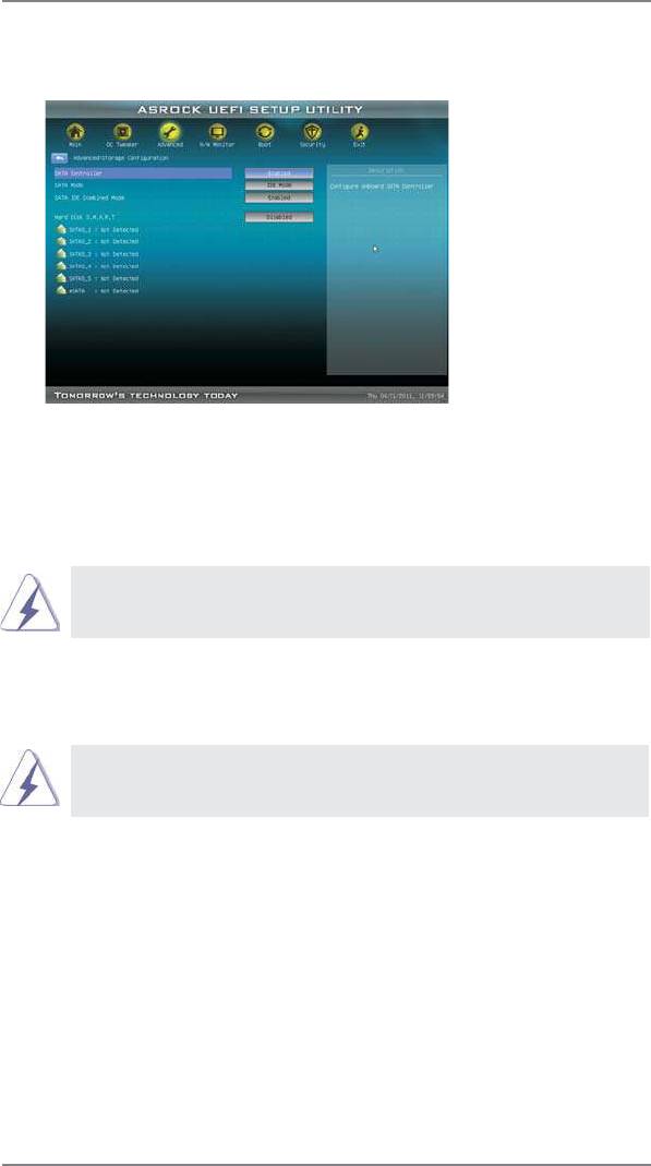
3.4.4 Storage Configuration
SATA Controller
Use this item to enable or disable the “SATA Controller” feature.
SATA Mode
Use this item to adjust SATA Mode. The default value of this option is [IDE
Mode]. Conf guration options: [AHCI Mode], [RAID Mode] and [IDE Mode].
If you set this item to RAID mode, it is suggested to install SATA ODD
driver on SATA3_5 and eSATA3 ports.
SATA IDE Combined Mode
This item is for SATA3_5 and eSATA3 ports. Use this item to enable or dis-
able SATA IDE combined mode. The default value is [Enabled].
If you want to build RAID on SATA3_5 and eSATA3 ports, please disable
this item.
Hard Disk S.M.A.R.T.
Use this item to enable or disable the S.M.A.R.T . (Self-Monitoring, Analy-
sis, and Reporting Technology) feature. Conf guration options: [Disabled],
[Auto] and [Enabled].
58

3.4.5 Super IO Configuration
Serial Port
Use this item to enable or disable the onboard serial port.
Serial Port Address
Use this item to set the address for the onboard serial port. Con f guration
options: [3F8h / IRQ4] and [3E8h / IRQ4].
Infrared Port
Use this item to enable or disable the onboard infrared port.
Infrared Port Address
Use this item to set the address for the onboard infrared port. Con f gura-
tion options: [2F8 / IRQ3] and [2E8 / IRQ3].
59

3.4.6 ACPI Configuration
Suspend to RAM
Use this item to select whether to auto-detect or disable the Suspend-to-
RAM feature. Select [Auto] will enable this feature if the OS supports it.
Check Ready Bit
Use this item to enable or disable the feature Check Ready Bit.
Restore on AC/Power Loss
This allows you to set the power state after an unexpected AC/power loss.
If [Power Off] is selected, the AC/power remains of f when the power re-
covers. If [Power On] is selected, the AC/power resumes and the system
starts to boot up when the power recovers.
PS/2 Keyboard Power On
Use this item to enable or disable PS/2 keyboard to turn on the system
from the power-soft-off mode.
PCI Devices Power On
Use this item to enable or disable PCI devices to turn on the system from
the power-soft-off mode.
Ring-In Power On
Use this item to enable or disable Ring-In signals to turn on the system
from the power-soft-off mode.
RTC Alarm Power On
Use this item to enable or disable R TC (Real Time Clock) to power on the
system.
USB Keyboard/Remote Power On
Use this item to enable or disable the system to wake from S5 using USB
Keyboard/Remote.
60


