Rotel RKB-650: Signal Connections
Signal Connections: Rotel RKB-650
13
English
Signal Connections
The RKB-650 provides standard conventional
input connections — unbalanced RCA type
connections as found on nearly all audio
equipment.
There is also a pair of SIGNAL OUTPUT LINK
connections for passing the input signal con-
nected to the “A” pair of channels on to an-
other audio component. Additionally, the
input signal to the “A” pair of channels can
be automatically linked to the inputs for the
“B” and/or “C” channels, so that a separate
input signal cable is not required for those
channels, for example in large systems where
the RKB-650 is being used to drive multiple
pairs of speakers.
RCA Inputs
See Figure 2
There are two RCA inputs for each of the
three pair of amplifier channels. These RCA
inputs accept audio signals from preamplifi-
ers or surround sound processors. Use high
quality audio interconnect cables for best
performance.
For each pair of amplifier channels, connect
the left channel output of your preamp to the
LEFT INPUT on the RKB-650. Connect the
right channel of your preamp to the RIGHT
INPUT. Make sure that the input slide switch
to the right of the RCA inputs is in the STE-
REO position.
Linking the Inputs
You can link the inputs for groups “B” and/
or “C” to the “A” inputs by placing the input
slide switch to the right of each pair of RCA
inputs in the LINK position. When linked, no
input connection is required for that group.
The input signal from the “A” group is sent
to the linked pair of channels, allowing you
to use four or six amplifier channels with the
same stereo input signals.
Input Level Controls
Three controls on the front panel, one for
each pair of channels, provide input level ad-
justments. These allow you to adjust the gain
of the amplifier to match other components in
the system. The A level control changes the
gain of the “A” channels; the B level control
changes the “B” channels; the C level con-
trol changes the “C” channels.
To adjust these controls, use a small, flat-
blade screwdriver. Turn the control clock-
wise to increase gain. Turn counterclockwise
to reduce gain.
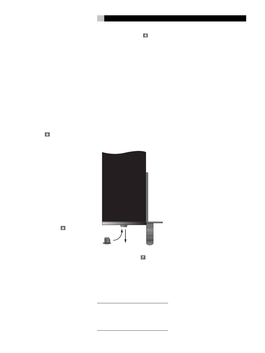
For easier adjustment, install the supplied vol-
ume control knobs by gently pressing them
onto the control shafts. Alternatively, you can
prevent inadvertant adjustment by installing
the supplied rubber plugs to conceal the vol-
ume controls.
Signal Output Link
This pair of RCA connections can be used
to pass the unprocessed input signals to an-
other audio component, for example to “dai-
sy-chain” an additional amplifier to drive a
second set of speakers. The input signals con-
nected to the “A” channels is also available
at these LINK outputs.
NOTE
:
These input signals from the “A” chan-
nels can also be linked to the “B” and/or “C”
inputs by playing the INPUT SELECT switch
associated with that pair of channels in the
LINK position.
Speakers
The RKB-650 has three groups of speaker
connectors, one for each pair of amplifier
channels.
Speaker Selection
The nominal impedance of the loudspeaker(s)
connected to the RKB-650
should be a mini-
mum of 4 ohms. When driving multiple pairs
of speakers connected in parallel, the effec-
tive impedance the amplifier sees is cut in
half. For example, when driving two pair of
8 ohm speakers, the amplifier sees a 4 ohm
load. When driving multiple speakers in par-
allel, select speakers with a nominal imped-
ance of 8 ohms or higher.
Speaker Wire Selection
Use insulated two-conductor stranded wire
to connect the RKB-650 to the speakers.
The size and quality of the wire can have
an audible effect on the performance of the
system. Standard speaker wire will work,
but can result in lower output or diminished
bass response, particularly over longer dis-
tances. In general, heavier wire will improve
the sound. For best performance, you may
want to consider special high-quality speak-
er cables. Your authorized Rotel dealer can
help in the selection of appropriate cables
for your system.
Polarity and Phasing
The polarity or positive/negative orientation
of the connections for every speaker and am-
plifier connection must be consistent so all the
speakers will be in phase. If the polarity of
one connection is mistakenly reversed, bass
output will be very weak and stereo imaging
degraded. All speaker wire is marked so you
can identify the two conductors. There may
be ribs or a stripe on the insulation of one
conductor. The wire may have clear insula-
tion with different color conductors (copper
and silver). There may be polarity indica-
tions printed on the insulation. Identify the
positive and negative conductors and be
consistent with every speaker and amplifier
connection.
Оглавление
- About Rotel
- AC Power and Control
- Signal Connections
- Troubleshooting
- Au sujet de Rotel
- Pour démarrer
- Alimentation secteur et mise sous tension
- Branchements des signaux en entrée
- Enceintes acoustiques
- Problèmes de fonctionnement
- Acerca de Rotel
- Para Empezar
- Alimentación y Control
- Conexiones de Señal
- Cajas Acústicas
- Problemas y Posibles Soluciones
- Alcune Parole Sulla Rotel
- Per Cominciare
- Alimentazione e comandi
- Collegamenti di segnale
- Diffusori
- Risoluzione dei problemi
- Die Firma Rotel
- Zu dieser Anleitung
- Netzspannung und Bedienung
- Signalanschlüsse
- Lautsprecher
- Störungssuche
- Wij van Rotel
- Aan de slag met de RKB-650
- Het aansluiten op het lichtnet en de bediening
- De ingangen
- Luidsprekers
- Technische gegevens
- Om Rotel
- Ström och strömfunktioner
- Högtalare
- Felsökning
- О компании ROTEL
- Ввод в эксплуатацию
- Подключение сети переменного тока и управление питанием
- Разъемы для сигналов
- Громкоговорители
- Характеристики
