Husqvarna 236: ASSEMBLY
ASSEMBLY: Husqvarna 236
ASSEMBLY
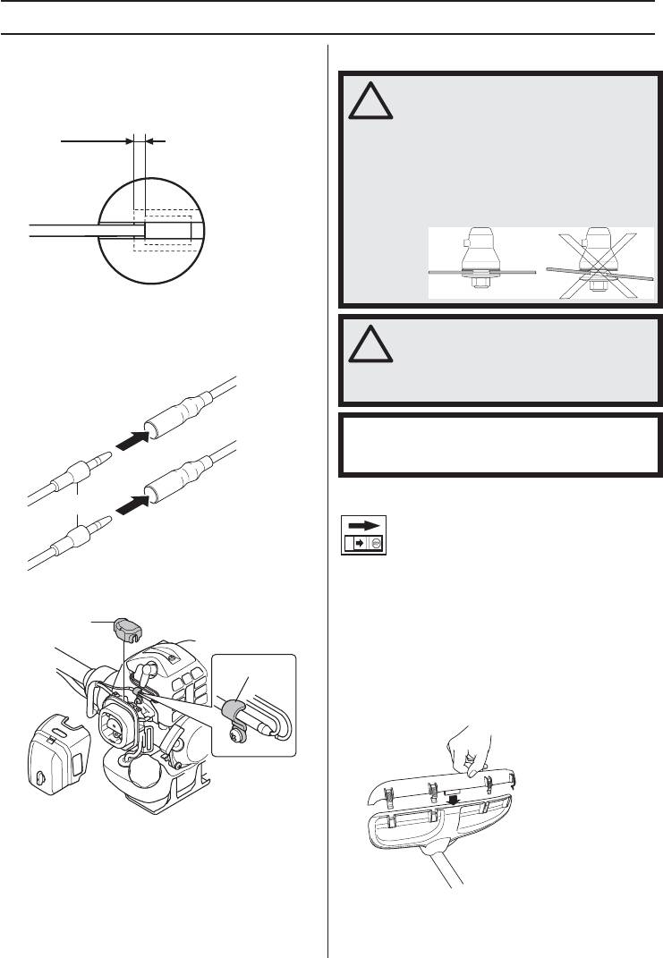
6 Adjust the cable adjuster sleeve so the stop on the
Fitting blades and trimmer heads
carburettor throttle cam just contacts the throttle stop
and the cable position keep 1-2 mm play between the
cable lug and the slotted fitting when the throttle
trigger is fully depressed.
1-2mm
7 When the throttle cable is adjusted correctly, tighten
the locking nut (G).
8 Plug the stop switch wires (H) into the matching
connectors from the engine. Note that wire polarity is
not important.
Fitting the guard extension
H
CAUTION! The guard extension shall always be fitted
9 Lap and fix the stop switch wires and connectors with
when using the trimmer head/plastic blades and
clamp (I).
combination guard. The guard extension shall always be
removed when using the grass blade and combination
J
guard.
Hook the blade guard/combination guard (A) onto the
fitting on the shaft and secure with the bolt.
I
Enter the guard extension guide in the slot of the
combination guard. Then click the guard extension into
position on the guard with the four quick-fasteners.
10 Fit the dust cover (J).
11 Refit the air filter cover.
66 – English
!
WARNING!
When fitting the cutting attachment it is
extremely important that the raised
section on the drive disc/support flange
engages correctly in the centre hole of
the cutting attachment. If the cutting
attachment is fitted incorrectly it can
result in serious and/or fatal personal
injury.
!
H1153278-30,236R.fm Page 66 Friday, December 4, 2009 1:21 PM
WARNING! Never use a cutting
attachment without an approved guard.
See the chapter on Technical data. If an
incorrect or faulty guard is fitted this can
cause serious personal injury.
IMPORTANT! If a saw blade or grass blade are to be
used the machine must be equipped with the correct
handlebar, blade guard and harness.
H1153278-30,236R.fm Page 67 Friday, December 4, 2009 1:21 PM
ASSEMBLY
The guard extension is removed easily using a
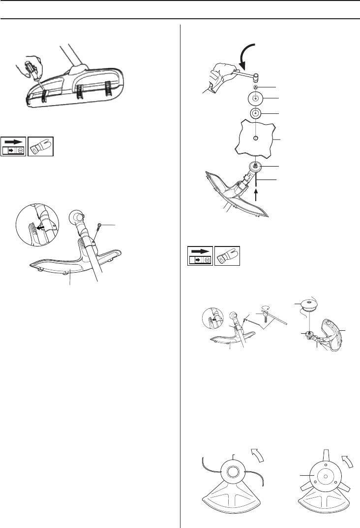
the spanner in the opposite direction to the direction
screwdriver, see illustration.
of rotation (Caution! left-hand thread).
G
E
F
Fitting a blade guard, grass blade and
grass cutter
D
• Hook the blade guard/combination guard (A) onto the
B
fitting on the shaft and secure with the bolt (L). Use the
recommended blade guard. See the Technical data
C
section. NB! Ensure that the guard extension is
removed.
L
Fitting the trimmer guard and trimmer
head
• Fit the correct trimmer guard (A) for use with the
trimmer head. NB! Ensure that the guard extension is
fitted.
A
• Fit the drive disc (B) on the output shaft.
H
• Turn the blade shaft until one of the holes in the drive
L
disc aligns with the corresponding hole in the gear
M
housing.
A
C
B
• Insert the locking pin (C) in the hole to lock the shaft.
• Place the blade (D), support cup (E) and support
A
M
L
flange (F) on the output shaft.
• Hook the trimmer guard/combination guard onto the
• Fit the nut (G). The nut must be tightened to a torque
fitting on the shaft and secure with the bolt (L).
of 35-50 Nm (3.5-5 kpm). Use the socket spanner in
• Fit the drive disc (B) on the output shaft.
the tool kit. Hold the shaft of the spanner as close to
the blade guard as possible. To tighten the nut, turn
• Turn the blade shaft until one of the holes in the drive
disc aligns with the corresponding hole in the gear
housing.
• Insert the locking pin (C) in the hole to lock the shaft.
• Screw on the trimmer head/plastic blades (H) in the
opposite direction to the direction of rotation.
H
H
• To dismantle, follow the instructions in the reverse
order.
English – 67
Оглавление
- A CLARA CIÓN DE LOS SÍMBOLOS
- ÍNDICE
- INTR ODUCCIÓN
- ¿Q UÉ ES Q UÉ?
- INSTR UCCIONES GENERALES DE SEGURID AD
- INSTR UCCIONES GENERALES DE SEGURID AD
- INSTR UCCIONES GENERALES DE SEGURID AD
- INSTR UCCIONES GENERALES DE SEGURID AD
- INSTRUCCIONES GENERALES DE SEGURIDAD
- INSTRUCCIONES GENERALES DE SEGURIDAD
- MONTAJE
- MONTAJE
- MONTAJE
- MANIPULACION DEL COMBUSTIBLE
- MANIPULACION DEL COMBUSTIBLE
- ARRANQUE Y PARADA
- ARRANQUE Y PARADA
- TÉCNICA DE TRABAJO
- TÉCNICA DE TRABAJO
- MANTENIMIENTO
- DATOS TECNICOS
- EXPLICAÇÃO DOS SÍMBOLOS
- ÍNDICE
- INTRODUÇÃO
- COMO SE CHAMA?
- INTRUÇÕES GERAIS DE SEGURANÇA
- INTRUÇÕES GERAIS DE SEGURANÇA
- INTRUÇÕES GERAIS DE SEGURANÇA
- INTRUÇÕES GERAIS DE SEGURANÇA
- INTRUÇÕES GERAIS DE SEGURANÇA
- INTRUÇÕES GERAIS DE SEGURANÇA
- MONTAGEM
- MONTAGEM
- MONTAGEM
- MANEJO DE COMBUSTÍVEL
- MANEJO DE COMBUSTÍVEL
- ARRANQUE E PARAGEM
- ARRANQUE E PARAGEM
- TÉCNICA DE TRABALHO
- TÉCNICA DE TRABALHO
- MANUTENÇÃO
- ESPECIFICAÇÕES TÉCNICAS
- KEY TO SYMBOLS
- CONTENTS
- INTRODUCTION
- WHAT IS WHAT?
- GENERAL SAFETY PRECAUTIONS
- GENERAL SAFETY PRECAUTIONS
- GENERAL SAFETY PRECAUTIONS
- GENERAL SAFETY PRECAUTIONS
- GENERAL SAFETY PRECAUTIONS
- ASSEMBLY
- ASSEMBLY
- ASSEMBLY
- FUEL HANDLING
- FUEL HANDLING
- STARTING AND STOPPING
- STARTING AND STOPPING
- WORKING TECHNIQUES
- WORKING TECHNIQUES
- MAINTENANCE
- TECHNICAL DATA
- Ÿ‘…ˆ… ‘ˆŒ‚‹‚
- ‘„…†ˆ…
- ‚‚…„…ˆ…
- —’ …‘’œ —’?
- ™ˆ… …„ˆ‘ˆŸ …‡‘‘’ˆ
- ™ˆ… …„ˆ‘ˆŸ …‡‘‘’ˆ
- ™ˆ… …„ˆ‘ˆŸ …‡‘‘’ˆ
- ™ˆ… …„ˆ‘ˆŸ …‡‘‘’ˆ
- ™ˆ… …„ˆ‘ˆŸ …‡‘‘’ˆ
- ™ˆ… …„ˆ‘ˆŸ …‡‘‘’ˆ
- ‘Š
- ‘Š
- ‘Š
- ‚ˆ‹ ™…ˆŸ ‘ ’‹ˆ‚Œ
- ‚ˆ‹ ™…ˆŸ ‘ ’‹ˆ‚Œ
- ‡“‘Š ˆ ‘’‚Š
- ‡“‘Š ˆ ‘’‚Š
- Œ…’ä ’›
- Œ…’ä ’›
- ’…•ˆ—…‘Š… ‘‹“†ˆ‚ˆ…
- ’…•ˆ—…‘Šˆ… •Š’…ˆ‘’ˆŠˆ
- S35
- T35, T35x
- T45, T45x
- T55x
- Trimmy SII


