ASRock z87 pro4: Chapter 2 Installation
Chapter 2 Installation: ASRock z87 pro4

Chapter 2 Installation
is is an ATX form factor motherboard. Before you install the motherboard, study
the conguration of your chassis to ensure that the motherboard ts into it.
Pre-installation Precautions
Take note of the following precautions before you install motherboard components
or change any motherboard settings.
•
Make sure to unplug the power cord before installing or removing the motherboard.
Failure to do so may cause physical injuries to you and damages to motherboard
components.
•
In order to avoid damage from static electricity to the motherboard’s components,
NEVER place your motherboard directly on a carpet. Also remember to use a grounded
wrist strap or touch a safety grounded object before you handle the components.
•
Hold components by the edges and do not touch the ICs.
•
Whenever you uninstall any components, place them on a grounded anti-static pad or
in the bag that comes with the components.
•
When placing screws to secure the motherboard to the chassis, please do not over-
tighten the screws! Doing so may damage the motherboard.
Z87 Pro4
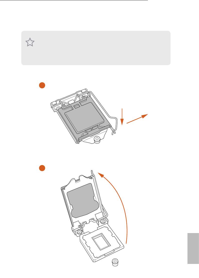
2.1 Installing the CPU
1. Before you insert the 1150-Pin CPU into the socket, please check if the PnP cap is on
the socket, if the CPU surface is unclean, or if there are any bent pins in the socket.
Do not force to insert the CPU into the socket if above situation is found. Otherwise,
the CPU will be seriously damaged.
2. Unplug all power cables before installing the CPU.
1
A
B
2
English
15
3
4
5
English
16

Z87 Pro4
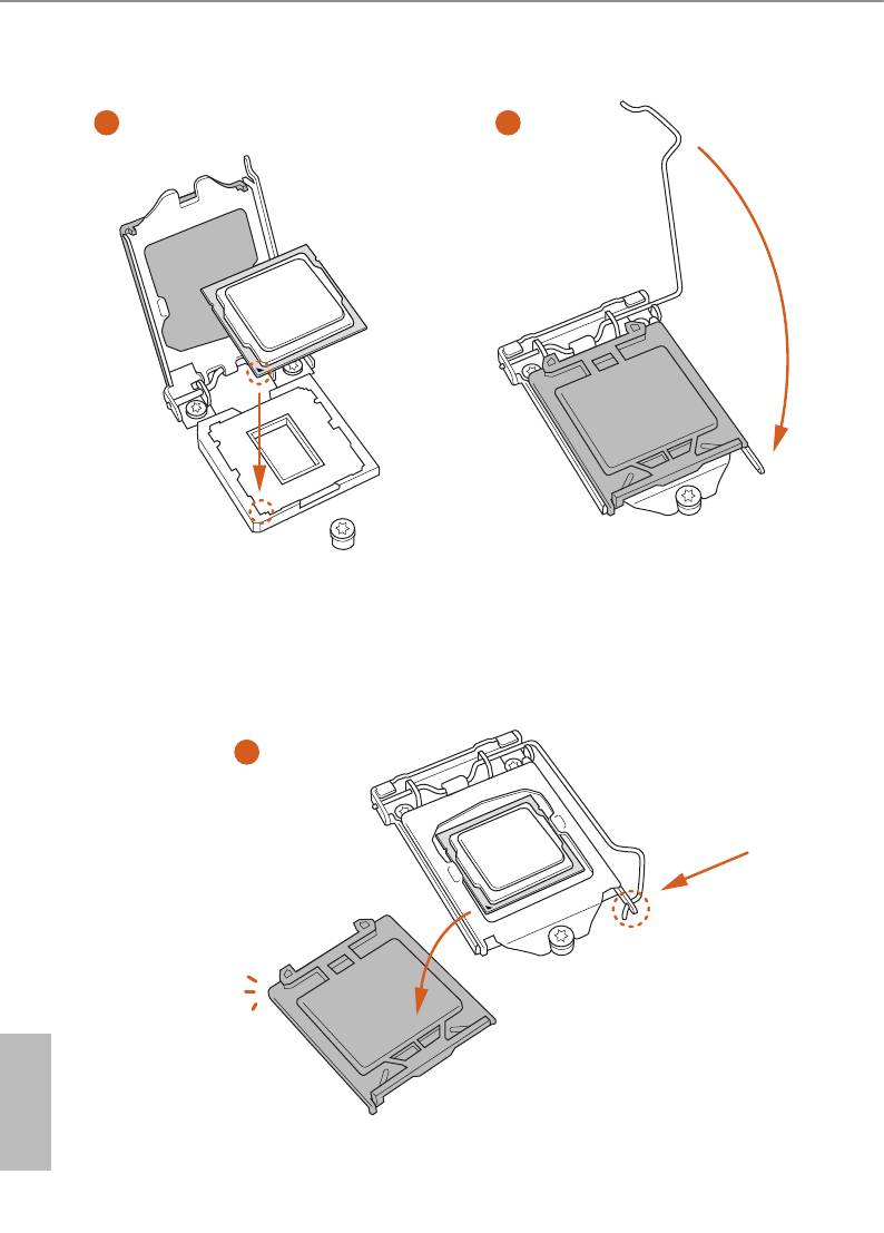
Please save and replace the cover if the processor is removed. e cover must be placed
if you wish to return the motherboard for aer service.
English
17
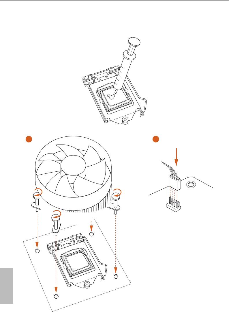
2.2 Installing the CPU Fan and Heatsink
1 2
FAN
CPU_
English
18
Z87 Pro4
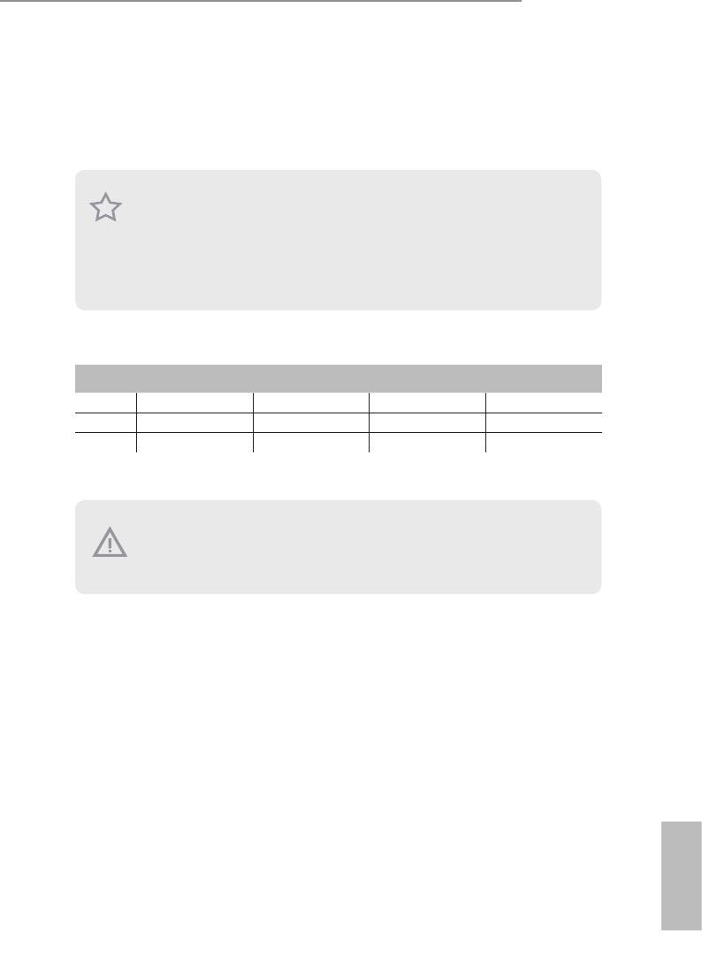
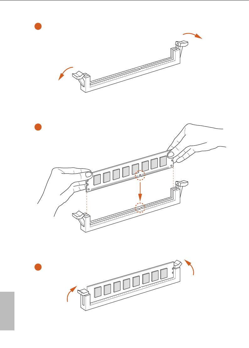
2.3 Installing Memory Modules (DIMM)
is motherboard provides four 240-pin DDR3 (Double Data Rate 3) DIMM slots,
and supports Dual Channel Memory Technology.
1. For dual channel conguration, you always need to install identical (the same
brand, speed, size and chip-type) DDR3 DIMM pairs.
2. It is unable to activate Dual Channel Memory Technology with only one or three
memory module installed.
3. It is not allowed to install a DDR or DDR2 memory module into a DDR3 slot;
otherwise, this motherboard and DIMM may be damaged.
Dual Channel Memory Conguration
Priority DDR3_A1 DDR3_A2 DDR3_B1 DDR3_B2
1 Populated Populated
2 Populated Populated
3 Populated Populated Populated Populated
e DIMM only ts in one correct orientation. It will cause permanent damage to
the motherboard and the DIMM if you force the DIMM into the slot at incorrect
orientation.
English
19
1
2
3
English
20
Z87 Pro4
2.4 Expansion Slots (PCI and PCI Express Slots)
ere are 2 PCI slots and 4 PCI Express slots on the motherboard.
Before installing an expansion card, please make sure that the power supply is
switched o or the power cord is unplugged. Please read the documentation of the
expansion card and make necessary hardware settings for the card before you start
the installation.
PCI slot:
e PCI1 and PCI2 slots are used to install expansion cards that have 32-bit PCI
interface.
PCIe slots:
PCIE1 (PCIe 3.0 x16 slot) is used for PCI Express x16 lane width graphics cards.
PCIE2 (PCIe 2.0 x1 slot) is used for PCI Express x1 lane width cards.
PCIE3 (PCIe 2.0 x16 slot) is used for PCI Express x4 lane width graphics cards.
PCIE4 (PCIe 2.0 x1 slot) is used for PCI Express x1 lane width cards.
PCIe Slot Congurations
PCIE1 PCIE3
Single Graphics Card x16 N/A
Two Graphics Cards in
x16 x4
TM
CrossFireX
Mode
For a better thermal environment, please connect a chassis fan to the motherboard’s
chassis fan connector (CHA_FAN1 or CHA_FAN2) when using multiple graphics
cards.
English
21
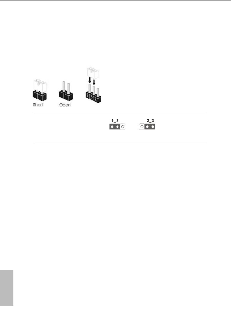
2.5 Jumpers Setup
e illustration shows how jumpers are setup. When the jumper cap is placed on
the pins, the jumper is “Short”. If no jumper cap is placed on the pins, the jumper
is “Open”. e illustration shows a 3-pin jumper whose pin1 and pin2 are “Short”
when a jumper cap is placed on these 2 pins.
Clear CMOS Jumper
(CLRCMOS1)
Clear CMOSDefault
(see p.10, No. 23)
CLRCMOS1 allows you to clear the data in CMOS. To clear and reset the system
parameters to default setup, please turn o the computer and unplug the power
cord from the power supply. Aer waiting for 15 seconds, use a jumper cap to
short pin2 and pin3 on CLRCMOS1 for 5 seconds. However, please do not clear
the CMOS right aer you update the BIOS. If you need to clear the CMOS when
you just nish updating the BIOS, you must boot up the system rst, and then shut
it down before you do the clear-CMOS action. Please be noted that the password,
date, time, and user default prole will be cleared only if the CMOS battery is
removed.
English
22
Z87 Pro4
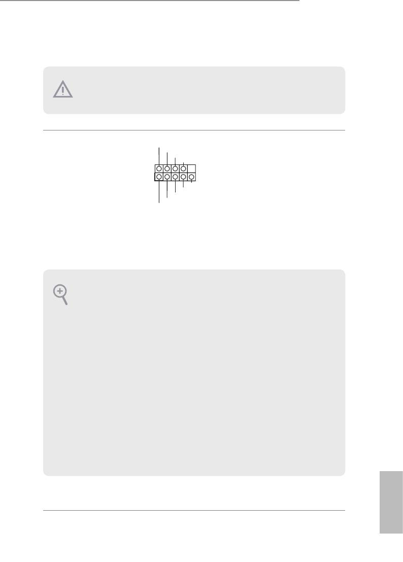
2.6 Onboard Headers and Connectors
Onboard headers and connectors are NOT jumpers. Do NOT place jumper caps over
these headers and connectors. Placing jumper caps over the headers and connectors
will cause permanent damage to the motherboard.
P LED+
System Panel Header
Connect the power
P LED-
P WRBTN#
(9-pin PANEL1)
GND
switch, reset switch and
(see p.10, No. 16)
system status indicator on
1
GND
the chassis to this header
R ESET#
GND
according to the pin
H DLED-
H DLED+
assignments below. Note
the positive and negative
pins before connecting
the cables.
PWRBTN (Power Switch):
Connect to the power switch on the chassis front panel. You may congure the way to
turn o your system using the power switch.
RESET (Reset Switch):
Connect to the reset switch on the chassis front panel. Press the reset switch to restart
the computer if the computer freezes and fails to perform a normal restart.
PLED (System Power LED):
Connect to the power status indicator on the chassis front panel. e LED is on when
the system is operating. e LED keeps blinking when the system is in S1/S3 sleep state.
e LED is o when the system is in S4 sleep state or powered o (S5).
HDLED (Hard Drive Activity LED):
Connect to the hard drive activity LED on the chassis front panel. e LED is on when
the hard drive is reading or writing data.
e front panel design may dier by chassis. A front panel module mainly consists
of power switch, reset switch, power LED, hard drive activity LED, speaker and etc.
When connecting your chassis front panel module to this header, make sure the wire
assignments and the pin assignments are matched correctly.
English
23
Power LED Header
Please connect the chassis
1
PLED-
(3-pin PLED1)
power LED to this header
PLED+
PLED+
(see p.10, No. 17)
to
indicate the system’s
power status.
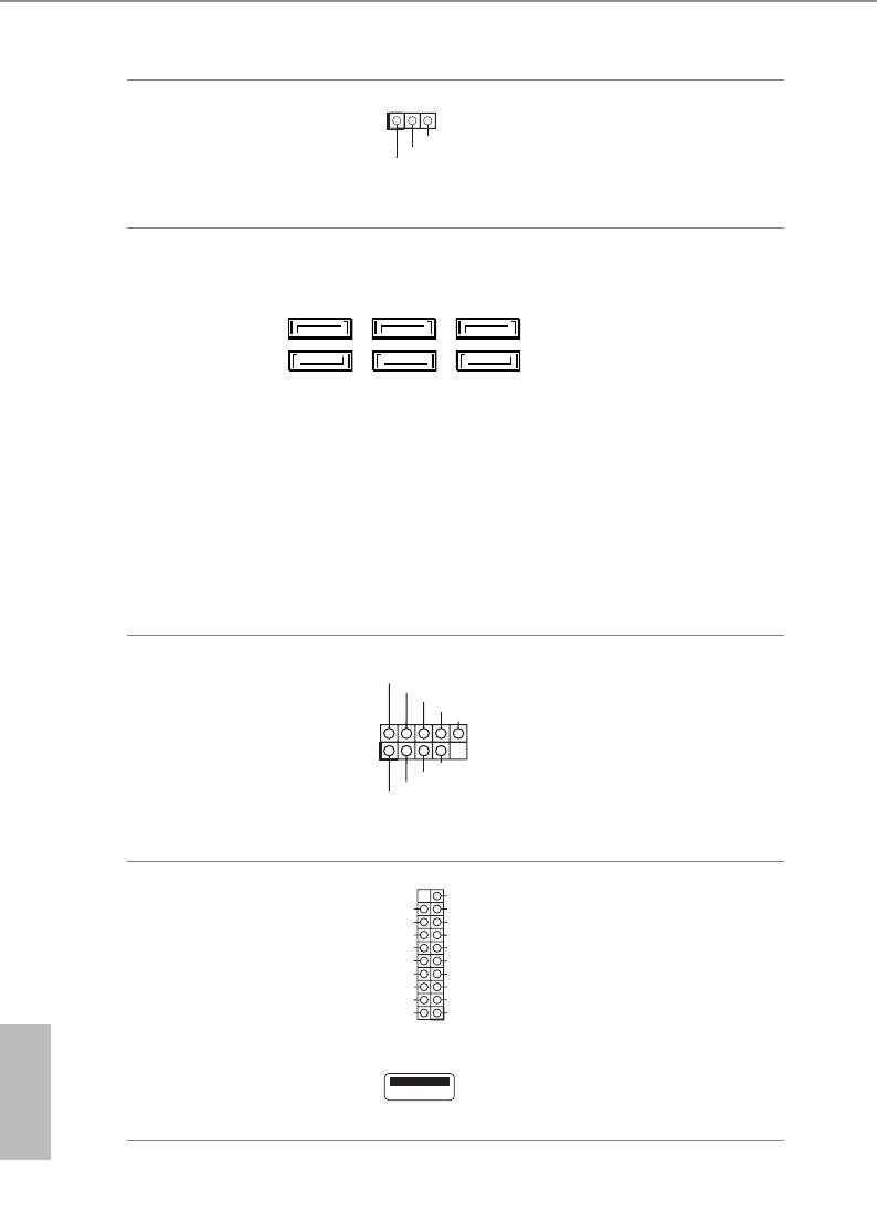
Serial ATA3 Connectors
ese six SATA3
(SATA3_0:
connectors support SATA
SATA3_4SATA3_0 SATA3_2
see p.10, No. 11)
data cables for internal
(SATA3_1:
storage devices with up to
see p.10, No. 20)
6.0 Gb/s data transfer rate.
SATA3_5SATA3_1 SATA3_3
(SATA3_2:
see p.10, No. 12)
(SATA3_3:
see p.10, No. 15)
(SATA3_4:
see p.10, No. 13)
(SATA3_5:
see p.10, No. 14)
USB 2.0 Headers
Besides four USB 2.0 ports
USB_PWR
P-
(9-pin USB4_5)
P+
on the I/O panel, there
GND
DUMMY
(see p.10, No. 21)
are two headers on this
(9-pin USB6_7)
motherboard. Each USB
1
GND
(see p.10, No. 22)
P+
2.0 header can support
P-
USB_PWR
two ports.
USB 3.0 Header
VbusVbus
Besides four USB 3.0 ports
Vbus
IntA_ PB_S SR X -
(19-pin USB3_4_5)
IntA_ PA_S SR X -
IntA_ PB_S SR X +
on the I/O panel, there
IntA_ PA_S SR X +
GND
(see p.10, No. 9)
GND
IntA_ PB_S ST X -
are two headers and one
IntA_ PA_S ST X -
IntA_ PB_S ST X +
IntA_ PA_S ST X +
(19-pin USB3_6_7)
GND
port on this motherboard.
GND
IntA_ PB_D -
IntA_ PA_D -
IntA_ PB_D +
(see p.10, No. 8)
Each USB 3.0 header can
IntA_ PA_D +
Dummy
1
support two ports.
English
(USB3_8)
(see p.10, No. 10)
24
Z87 Pro4
Front Panel Audio Header
GN D
is header is for
P RESENCE#
M IC_RET
(9-pin HD_AUDIO1)
connecting audio devices
OUT_RET
(see p.10, No. 28)
to the front audio panel.
1
O UT2_L
J _SENSE
O UT2_R
M IC2_R
M IC2_L
1. High Denition Audio supports Jack Sensing, but the panel wire on the chassis must
support HDA to function correctly. Please follow the instructions in our manual and
chassis manual to install your system.
2. If you use an AC’97 audio panel, please install it to the front panel audio header by
the steps below:
A. Connect Mic_IN (MIC) to MIC2_L.
B. Connect Audio_R (RIN) to OUT2_R and Audio_L (LIN) to OUT2_L.
C. Connect Ground (GND) to Ground (GND).
D. MIC_RET and OUT_RET are for the HD audio panel only. You don’t need to
connect them for the AC’97 audio panel.
E. To activate the front mic, go to the “FrontMic” Tab in the Realtek Control panel
and adjust “Recording Volume”.
Chassis Speaker Header
DUMMY
SPEAKER
Please connect the chassis
(4-pin SPEAKER1)
1
speaker to this header.
+5V
DUMMY
(see p.10, No. 18)
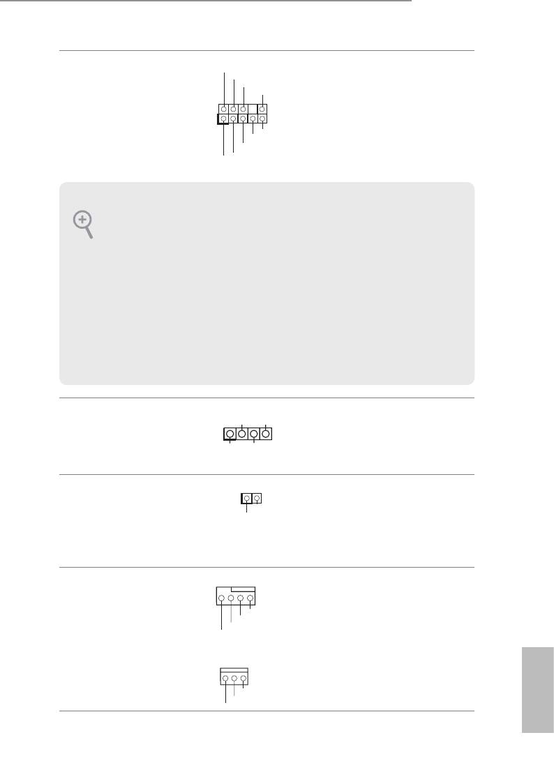
SPDIF Out Connector
Please connect the
(2-pin SPDIF_OUT1)
SPDIF_OUT connector of
(see p.10, No. 27)
a HDMI VGA card to this
header with a cable.
Chassis and Power Fan
Please connect fan cables
Connectors
to the fan connectors and
GND
+12V
(4-pin CHA_FAN1)
FAN_SPEE D
match the black wire to
FAN_SPEE D _CONTROL
(see p.10, No. 19)
the ground pin.
(3-pin CHA_FAN2)
(see p.10, No. 29)
English
25
GND
+12V
FAN_SPEED
1
GN D
SP D IFOUT
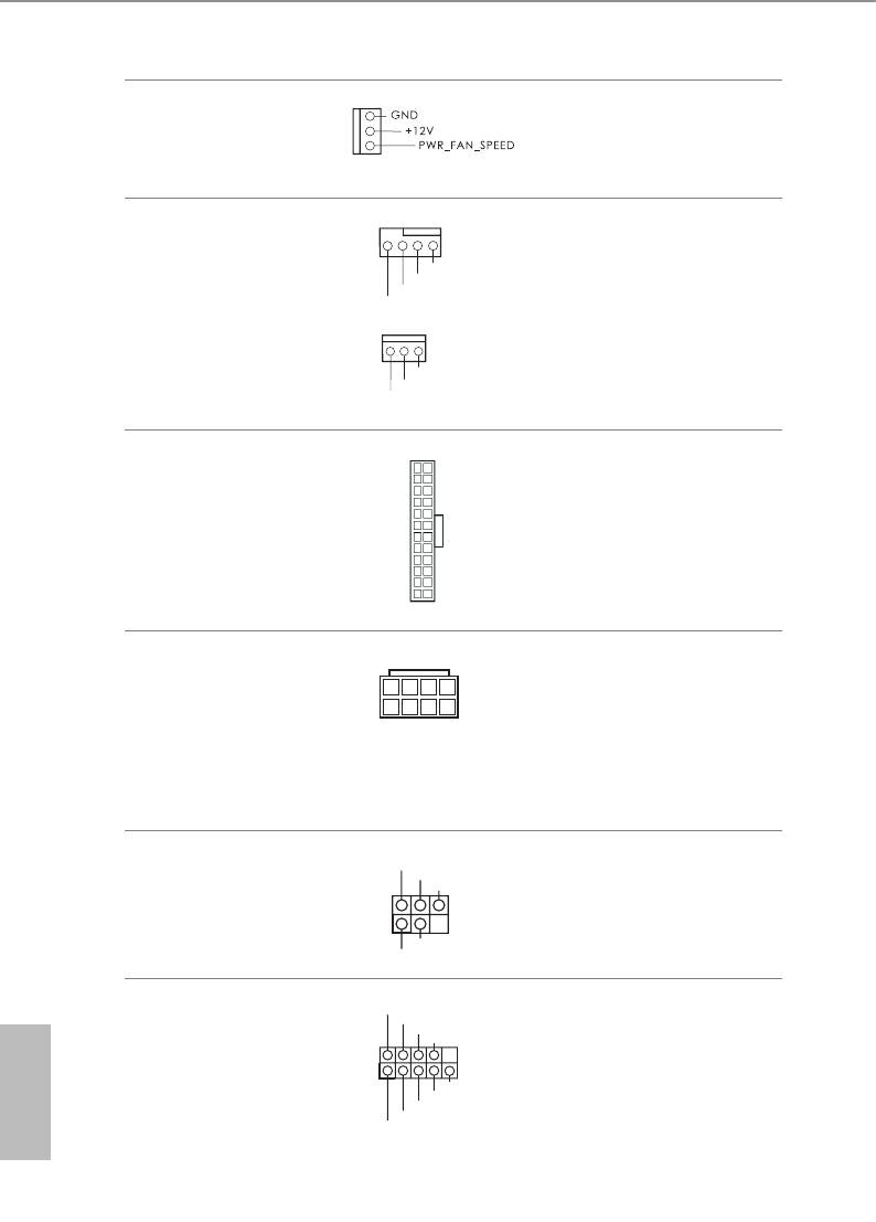
(3-pin PWR_FAN1)
(see p.10, No. 1)
CPU Fan Connectors
is motherboard pro-
(4-pin CPU_FAN1)
vides a 4-Pin CPU fan
GND
+12V
(see p.10, No. 3)
FAN_SPEE D
(Quiet Fan) connector.
FAN_SPEE D _CONTROL
If you plan to connect a
(3-pin CPU_FAN2)
3-Pin CPU fan, please
(see p.10, No. 4)
connect it to Pin 1-3.
ATX Power Connector
12
24
is motherboard pro-
(24-pin ATXPWR1)
vides a 24-pin ATX power
(see p.10, No. 7)
connector. To use a 20-pin
ATX power supply, please
plug it along Pin 1 and Pin
1
13
13.
ATX 12V Power
is motherboard pro-
Connector
vides an 8-pin ATX 12V
(8-pin ATX12V1)
power connector. To use a
(see p.10, No. 2)
4-pin ATX power supply,
please plug it along Pin 1
and Pin 5.
Infrared Module Header
IRTX
is header supports an optional
+5VSB
DUMMY
(5-pin IR1)
wireless transmitting and
(see p.10, No. 24)
receiving infrared module.
1
GND
IRRX
RRXD1
Serial Port Header
is COM1 header
DDTR#1
DDSR#1
(9-pin COM1)
CCTS#1
supports a serial port
English
(see p.10, No. 25)
module.
1
RRI#1
RRTS#1
GND
TTXD1
DDCD#1
26
GND
+12V
FAN_SPEED
8 5
4 1

Z87 Pro4
TPM Header
is connector supports
(17-pin TPMS1)
Trusted Platform Module
(see p.10, No. 26)
(TPM) system, which can
securely store keys, digital
certicates, passwords,
and data. A TPM system
also helps enhance
network security, protects
digital identities, and
ensures platform integrity.
English
27
1
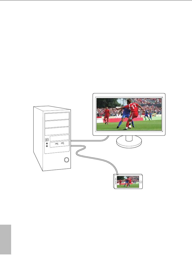
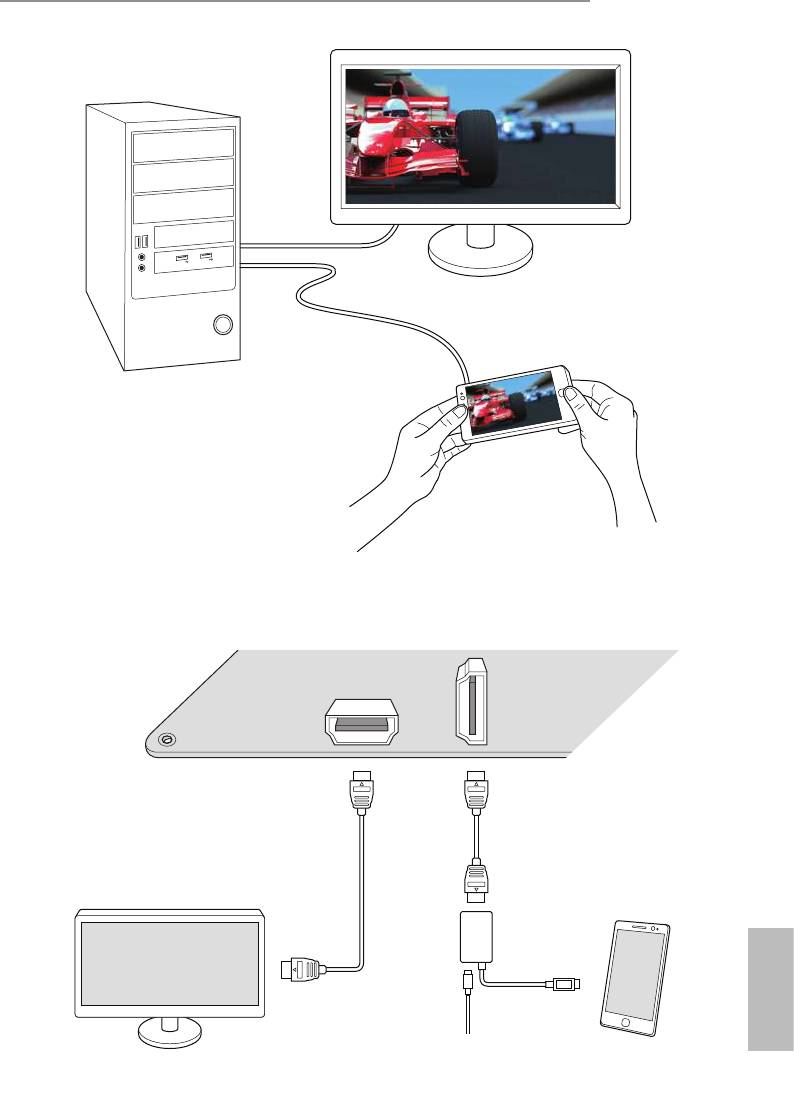
2.7 Using the HDMI-In Port
e HDMI-In port on this motherboard lets you easily switch between PC screen
(on-board VGA) and external video source on the same monitor. is function
saves you the hassle of switching cables back and forth when you want to display
the screen of another device, such as smartphone, tablet, camcorder, DVD player, or
another PC, onto the PC monitor.
Another useful feature of this function is that external video source can be viewed
even when your PC is in standby mode or powered o. For example, you can play
smartphone games or watch tablet video on your PC screen.
USB
3
.
0
USB
3
.
0
English
28
Z87 Pro4
USB
3
.
0
USB
3
.
0
Connection Diagram
HDMI
Adapter
English
Power Source
29
Step 1
Connect your monitor to the HDMI-Out port on the motherboard via an HDMI
cable.
Step 2
Connect an external devices with HDMI output to the HDMI-In port on the
motherboard via an HDMI cable.
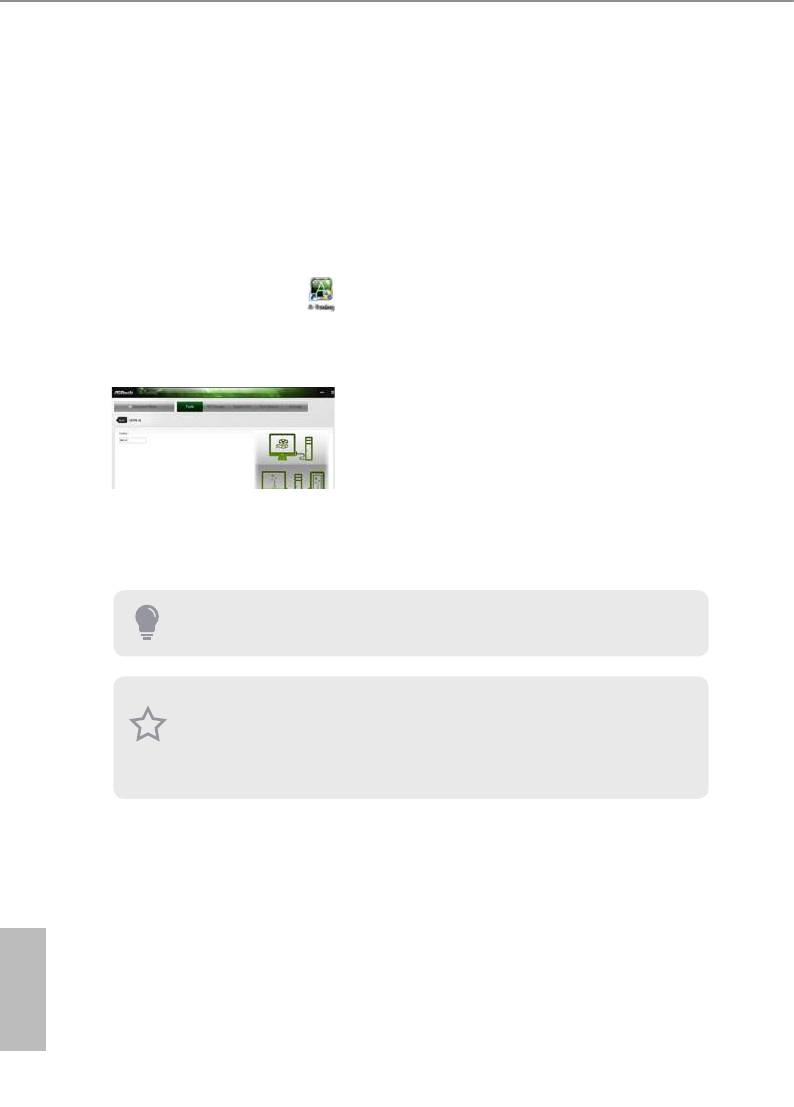
Step 3
Double-click the “A-Tuning“ icon on the desktop and nd "HDMI-IN"
function in "Tools" tab.
Drag the switch right or le to enable Onboard (on-board PC screen) or HDMI
(HDMI-In Source).
or
Use the hotkey to switch between on-board PC screen or HDMI-In Source.
To change the hotkey, click the textbox next to “Hotkey:” and enter the action for the
key.
1. If there is no video displayed on your monitor, make sure that the cables are
properly connected and make sure that “Deep S5” option in BIOS SETUP is set to
[Disable].
2. If required, connect a power source to the adapter that lets the smartphone/tablet
output HDMI signal.
English
30
Z87 Pro4
TM
TM
2.8 CrossFireX
and Quad CrossFireX
Operation Guide
TM
TM
is motherboard supports CrossFireX
and Quad CrossFireX
that allows you to
TM
install up to two identical PCI Express x16 graphics cards. Currently CrossFireX
TM
®
and Quad CrossFireX
are supported with Windows
7 / 7 64-bit / 8 / 8 64-bit OS.
TM
1. You should only use identical CrossFireX
-ready graphics cards that are AMD
certied.
TM
2. Make sure that your graphics card driver supports AMD CrossFireX
technology.
Download the drivers from the AMD’s website: www.amd.com
3. Make sure that your power supply unit (PSU) can provide at least the minimum
power your system requires. It is recommended to use a AMD certied PSU. Please
refer to the AMD’s website for details.
TM
4. If you pair a 12-pipe CrossFireX
Edition card with a 16-pipe card, both cards will
TM
operate as 12-pipe cards while in CrossFireX
mode.
TM
5. Dierent CrossFireX
cards may require dierent methods to enable CrossFi-
TM
reX
. Please refer to AMD graphics card manuals for detailed installation guide.
TM
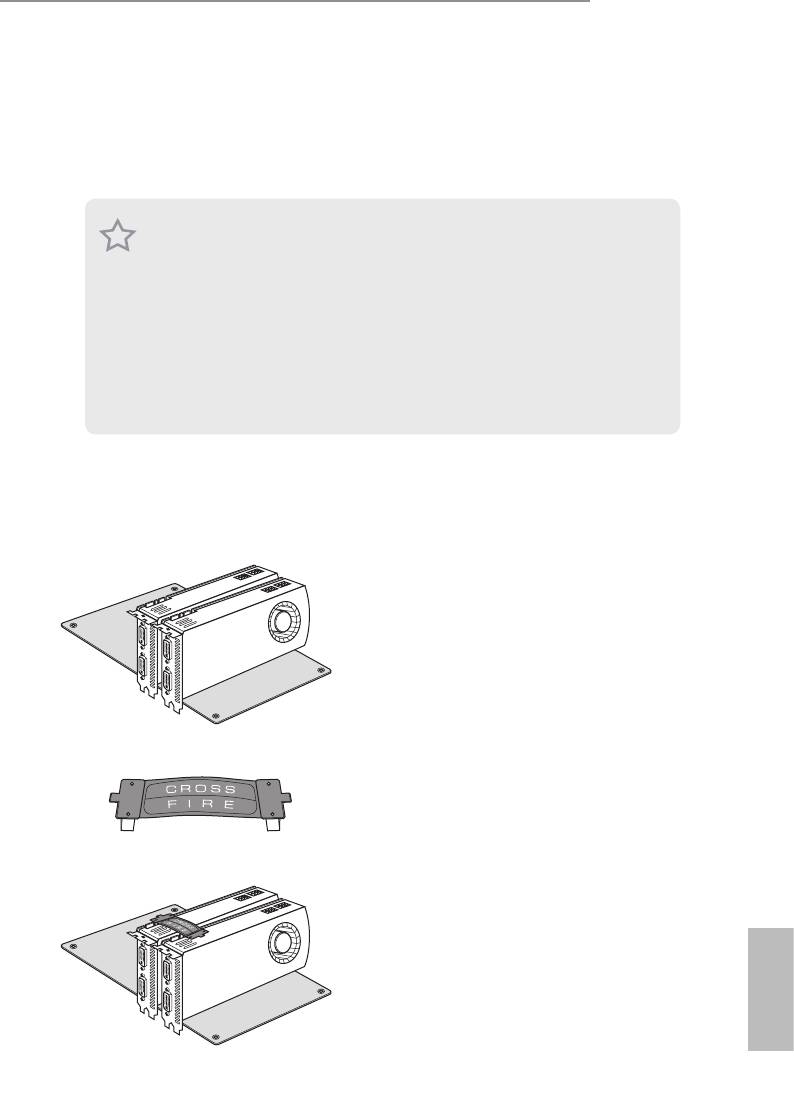
2.8.1 Installing Two CrossFireX
-Ready Graphics Cards
Step 1
Insert one graphics card into PCIE1 slot
and the other graphics card to PCIE3 slot.
Make sure that the cards are properly
seated on the slots.
Step 2
Connect two graphics cards by installing
a CrossFire Bridge on the CrossFire Bridge
CrossFire Bridge
Interconnects on the top of the graphics
cards. (e CrossFire Bridge is provided
with the graphics card you purchase, not
bundled with this motherboard. Please
refer to your graphics card vendor for
details.)
English
31
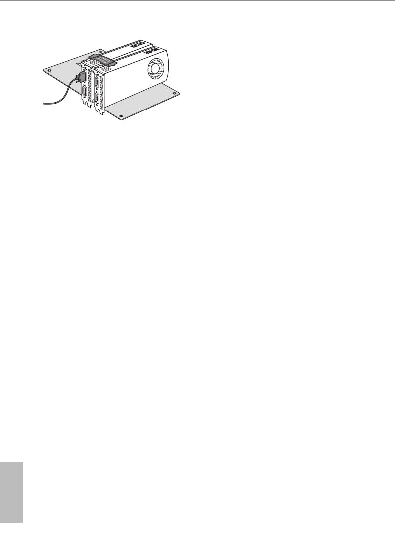
Step 3
Connect a VGA cable or a DVI cable to the
monitor connector or the DVI connec-
tor of the graphics card that is inserted to
PCIE1 slot.
English
32
Z87 Pro4
2.8.2 Driver Installation and Setup
Step 1
Power on your computer and boot into OS.
Step 2
Remove the AMD drivers if you have any VGA drivers installed in your system.
e Catalyst Uninstaller is an optional download. We recommend using this utility to
uninstall any previously installed Catalyst drivers prior to installation. Please check
AMD’s website for AMD driver updates.
Step 3
Install the required drivers and CATALYST Control Center then restart your
computer. Please check AMD’s website for details.
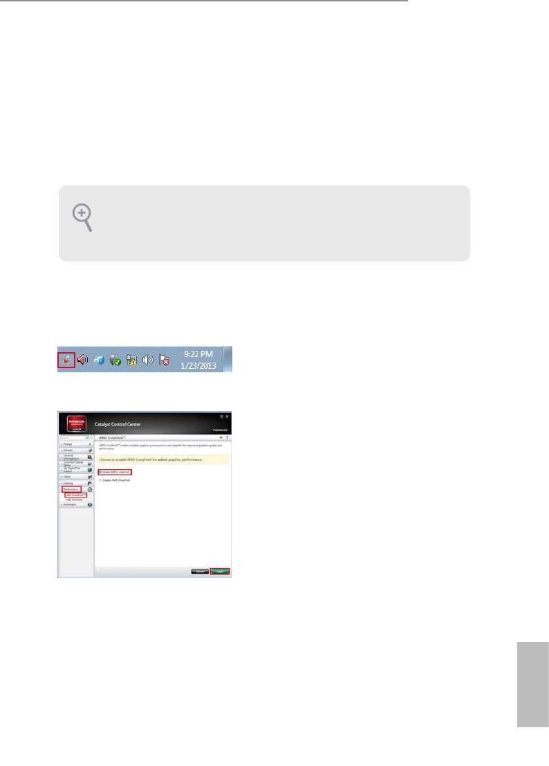
Step 4
Double-click the AMD Catalyst Control
®
AMD Catalyst Control Center
Center icon in the Windows
system tray.
Step 5
In the le pane, click Performance and
TM
then AMD CrossFireX
. en select
Enable AMD CrossFireX and click Apply.
Select the GPU number according to your
graphics card and click Apply.
English
33


