ASRock FM2A85X Extreme4 – страница 2
Инструкция к Материнской Плате ASRock FM2A85X Extreme4
21
ASRock FM2A85X Extreme4 Motherboard
English
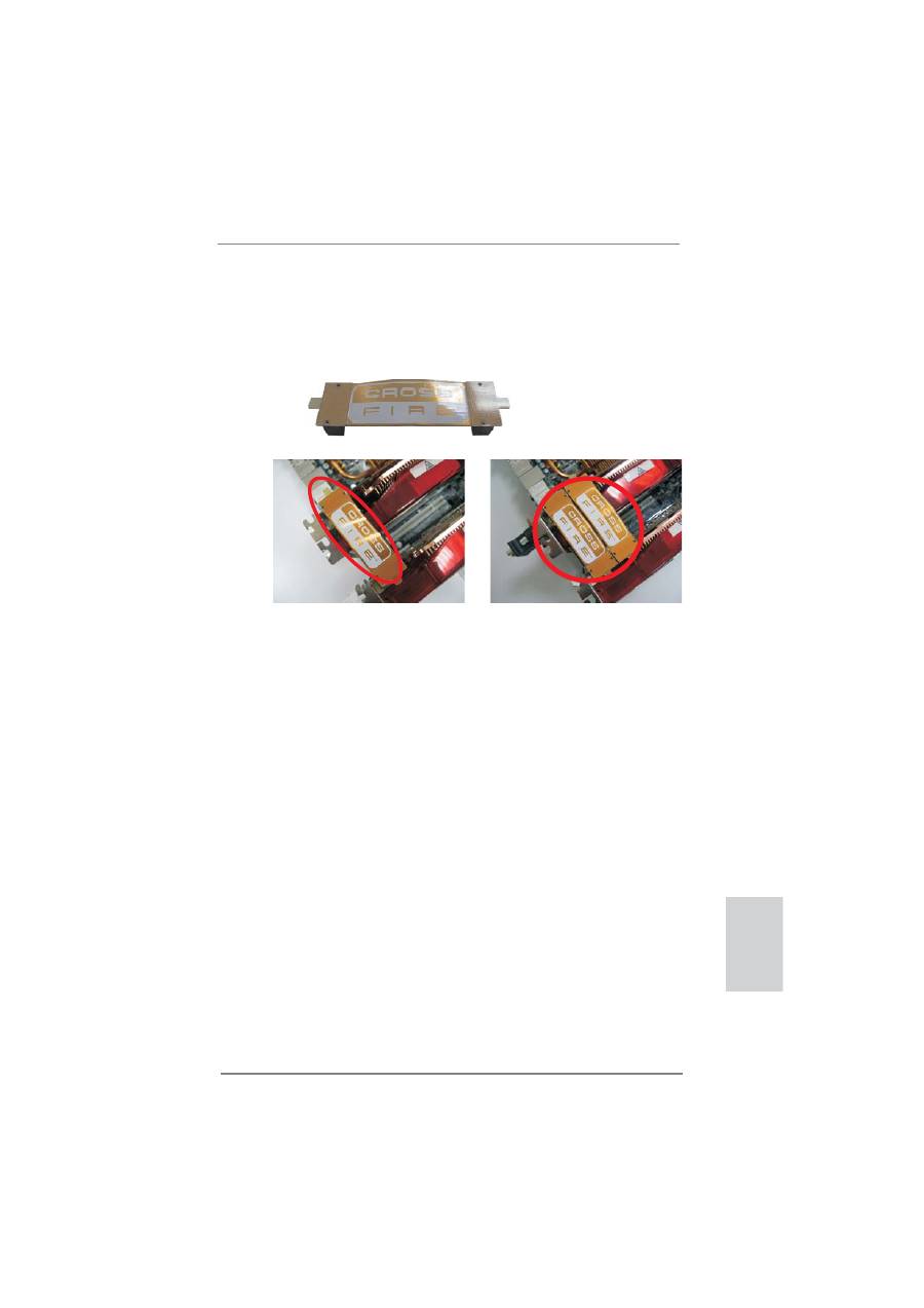
Step 2. Connect two Radeon graphics cards by installing CrossFire Bridge on
CrossFire Bridge Interconnects on the top of Radeon graphics cards.
(CrossFire Bridge is provided with the graphics card you purchase, not
bundled with this motherboard. Please refer to your graphics card vendor
for details.)
CrossFire Bridge
or
Step 3. Connect the DVI monitor cable to the DVI connector on the Radeon graph-
ics card on PCIE2 slot. (You may use the DVI to D-Sub adapter to convert
the DVI connector to D-Sub interface, and then connect the D-Sub monitor
cable to the DVI to D-Sub adapter.)
22
ASRock FM2A85X Extreme4 Motherboard
English
The Catalyst Uninstaller is an optional download. We recommend using this
utility to uninstall any previously installed Catalyst drivers prior to installation.
Please check AMD website for AMD driver updates.
Step 3. Install the required drivers to your system.
For
Windows
®
8 / 7 / Vista
TM
OS:
Install the CATALYST Control Center. Please check AMD website for de-
tails.
Step 4. Restart your computer.
Step 5. Install the VGA card drivers to your system, and restart your computer.
Then you will
fi
nd “ATI Catalyst Control Center” on your Windows
®
taskbar.
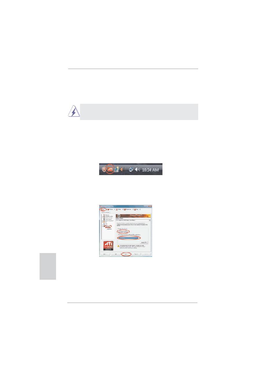
ATI Catalyst Control Center
2.5.2 Driver Installation and Setup
Step 1. Power on your computer and boot into OS.
Step 2. Remove the AMD driver if you have any VGA driver installed in your sys-
tem.
Step 6. Double-click “ATI Catalyst Control Center”. Click “View”, select “CrossFi-
reX
TM
”, and then check the item “Enable CrossFireX
TM
”. Select “2 GPUs”
and click “Apply” (if you install two Radeon graphics cards).

23
ASRock FM2A85X Extreme4 Motherboard
English
Although you have selected the option “Enable CrossFire
TM
”, the Cross-
FireX
TM
function may not work actually. Your computer will automatically
reboot. After restarting your computer, please con
fi
rm whether the option
“Enable CrossFire
TM
” in “ATI Catalyst Control Center” is selected or not;
if not, please select it again, and then you are able to enjoy the bene
fi
t of
CrossFireX
TM
feature.
Step 7. You can freely enjoy the bene
fi
t of CrossFireX
TM
or Quad CrossFireX
TM
feature.
* CrossFireX
TM
appearing here is a registered trademark of AMD Technologies Inc., and is
used only for identi
fi
cation or explanation and to the owners’ bene
fi
t, without intent to infringe.
* For further information of AMD CrossFireX
TM
technology, please check AMD website for
updates and details.
24
ASRock FM2A85X Extreme4 Motherboard
English
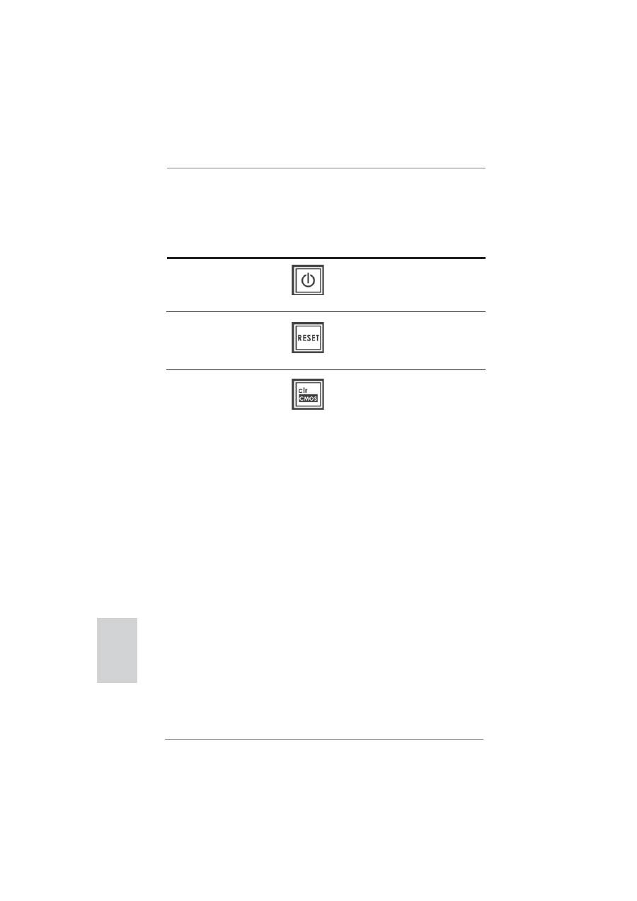
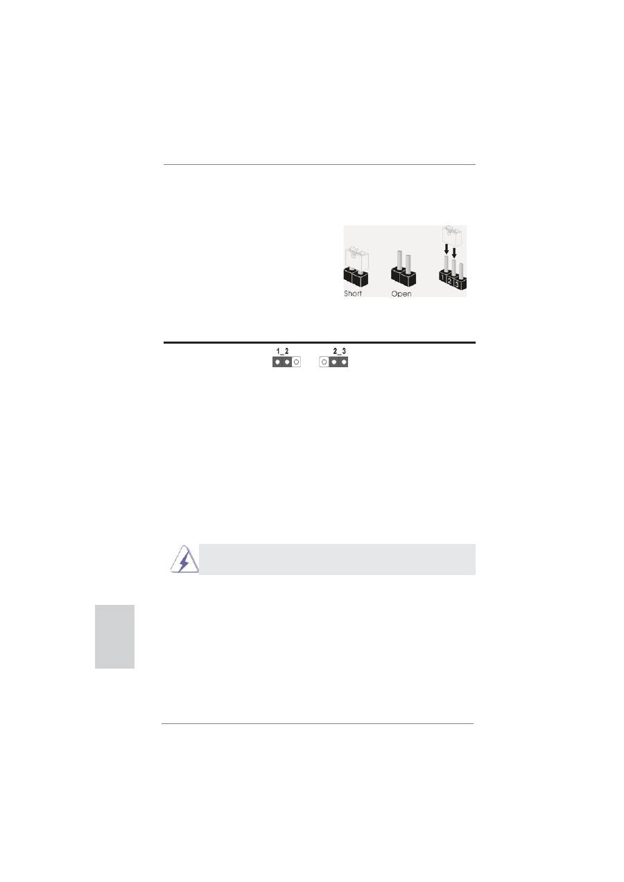
2.6 Jumpers Setup
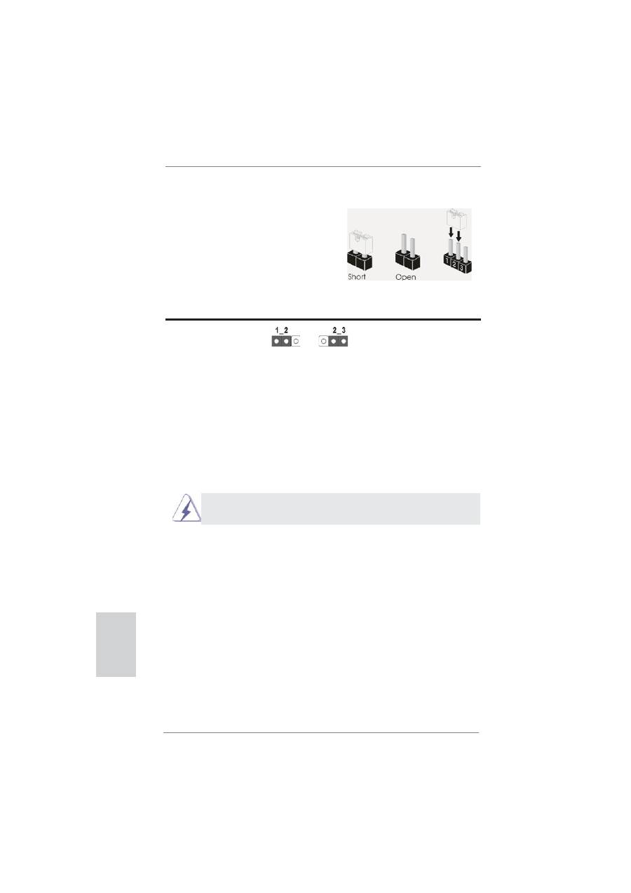
The illustration shows how jumpers are
setup. When the jumper cap is placed on
pins, the jumper is “Short”. If no jumper cap
is placed on pins, the jumper is “Open”. The
illustration shows a 3-pin jumper whose
pin1 and pin2 are “Short” when jumper cap
is placed on these 2 pins.
Jumper Setting
Description
Clear CMOS Jumper
(CLRCMOS1)
(see p.2, No. 27)
Note: CLRCMOS1 allows you to clear the data in CMOS. To clear and reset the
system parameters to default setup, please turn off the computer and unplug
the power cord from the power supply. After waiting for 15 seconds, use a
jumper cap to short pin2 and pin3 on CLRCMOS1 for 5 seconds. However,
please do not clear the CMOS right after you update the BIOS. If you need
to clear the CMOS when you just
fi
nish updating the BIOS, you must boot
up the system
fi
rst, and then shut it down before you do the clear-CMOS ac-
tion. Please be noted that the password, date, time, user default pro
fi
le, 1394
GUID and MAC address will be cleared only if the CMOS battery is removed.
Clear CMOS
Default
The Clear CMOS Switch has the same function as the Clear CMOS
jumper.
25
ASRock FM2A85X Extreme4 Motherboard
English
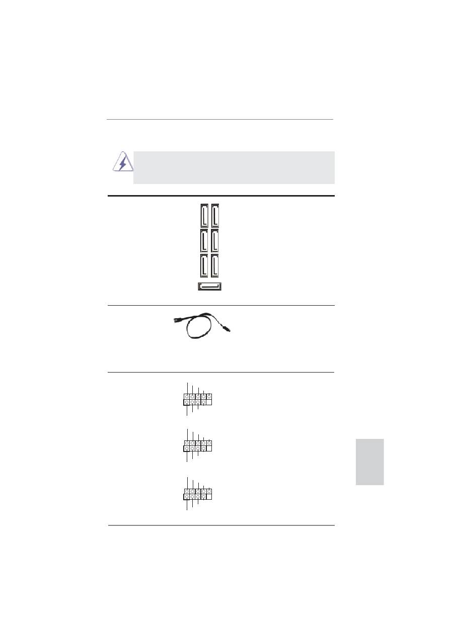
2.7 Onboard Headers and Connectors
Onboard headers and connectors are NOT jumpers. Do NOT place
jumper caps over these headers and connectors. Placing jumper caps
over the headers and connectors will cause permanent damage of the
motherboard!
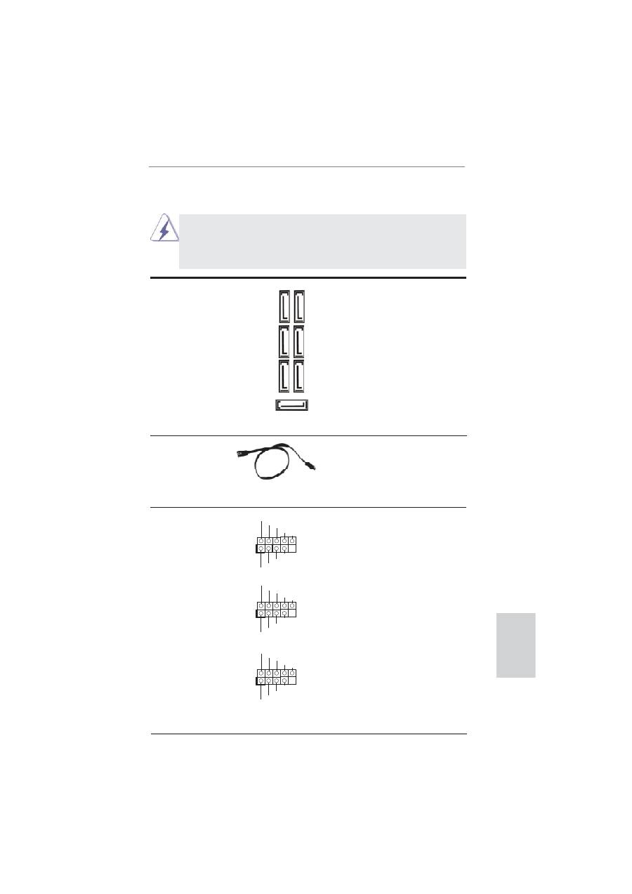
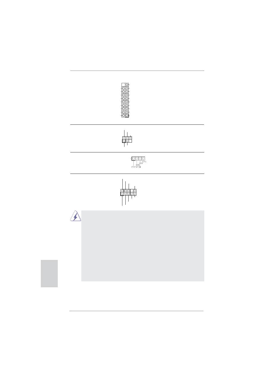
Serial ATA3 Connectors
These seven Serial ATA3
(SATA3_1: see p.2, No. 13)
(SATA3) connectors support
(SATA3_2: see p.2, No. 12)
SATA data cables for internal
(SATA3_3: see p.2, No. 14)
storage devices. The current
(SATA3_4: see p.2, No. 15)
SATA3 interface allows up to
(SATA3_5: see p.2, No. 19)
6.0 Gb/s data transfer rate.
(SATA3_6: see p.2, No. 16)
(SATA3_7: see p.2, No. 17)
Serial ATA (SATA)
Either end of the SATA data
Data Cable
cable can be connected to the
(Optional)
SATA3 hard disk or the SATA3
connector on this motherboard.
USB 2.0 Headers
Besides two default USB 2.0
(9-pin USB3_4)
ports on the I/O panel, there
(see p.2 No. 30)
are three USB 2.0 headers on
this motherboard. Each USB 2.0
header can support two USB
2.0
ports.
(9-pin USB5_6)
(see p.2 No. 29)
(9-pin USB7_8)
(see p.2 No. 28)
1
USB_PWR
P-4
P+4
USB_PWR
P-3
P+3
GND
GND
DUMMY
1
USB_PWR
P-6
P+6
USB_PWR
P-5
P+5
GND
GND
DUMMY
1
USB_PWR
P-8
P+8
USB_PWR
P-7
P+7
GND
GND
DUMMY
SA
TA3_6 SA
TA3_3 SA
TA3_1
SA
TA3_7 SA
TA3_4 SA
TA3_2
SATA3_5
26
ASRock FM2A85X Extreme4 Motherboard
English
Infrared Module Header
This header supports an
(5-pin IR1)
optional wireless transmitting
(see p.2 No. 25)
and receiving infrared module.
Front Panel Audio Header
This is an interface for the front
(9-pin HD_AUDIO1)
panel audio cable that allows
(see p.2 No. 34)
convenient connection and
control of audio devices.
Consumer Infrared Module Header
This header can be used to
(4-pin CIR1)
connect the remote
(see p.2 No. 31)
controller
receiver.
1
IRTX
+5VSB
DUMMY
IRRX
GND
J_SENSE
OUT2_L
1
MIC_RET
PRESENCE#
GND
OUT2_R
MIC2_R
MIC2_L
OUT_RET
1. High De
fi
nition Audio supports Jack Sensing, but the panel wire on
the chassis must support HDA to function correctly. Please follow the
instruction in our manual and chassis manual to install your system.
2. If you use AC’97 audio panel, please install it to the front panel audio
header as below:
A. Connect Mic_IN (MIC) to MIC2_L.
B. Connect Audio_R (RIN) to OUT2_R and Audio_L (LIN) to OUT2_L.
C. Connect Ground (GND) to Ground (GND).
D. MIC_RET and OUT_RET are for HD audio panel only. You don’t
need to connect them for AC’97 audio panel.
E. To activate the front mic.
For Windows
®
8 / 8 64-bit / 7 / 7 64-bit / Vista
TM
/ Vista
TM
64-bit OS:
Go to the “FrontMic” Tab in the Realtek Control panel. Adjust
“Recording Volume”.
USB 3.0 Header
Besides six default USB 3.0
(19-pin USB3_7_8)
ports on the I/O panel, there is
(see p.2, No. 10)
one USB 3.0 header on this
motherboard. This USB 3.0
header can support two USB 3.0
ports.
IntA_P8_D+
DUMMY
IntA_P8_D-
GND
IntA_P8_SSTX+
GND
IntA_P8_SSTX-
IntA_P8_SSRX+
IntA_P8_SSRX-
Vbus
Vbus
Vbus
IntA_P7_SSRX-
IntA_P7_SSRX+
GND
IntA_P7_SSTX-
IntA_P7_SSTX+
GND
IntA_P7_D-
IntA_P7_D+
27
ASRock FM2A85X Extreme4 Motherboard
English
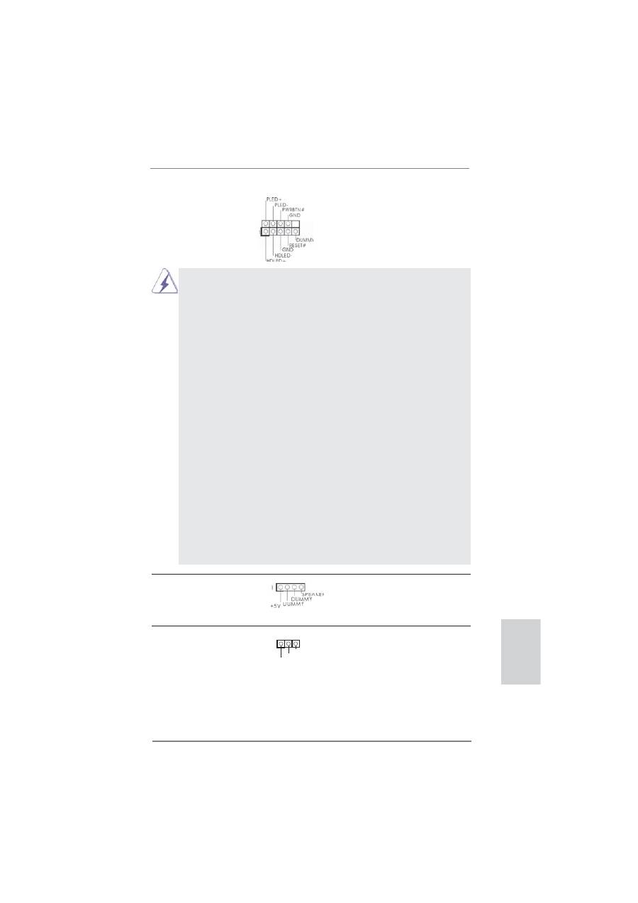
Power LED Header
Please connect the chassis
(3-pin PLED1)
power LED to this header to
(see p.2 No. 26)
indicate system power status.
The LED is on when the system
is operating. The LED keeps
blinking in S1 state. The LED is
off in S3/S4 state or S5 state
(power
off).
Chassis Speaker Header
Please connect the chassis
(4-pin SPEAKER 1)
speaker to this header.
(see p.2 No. 23)
1
PLED+
PLED+
PLED-
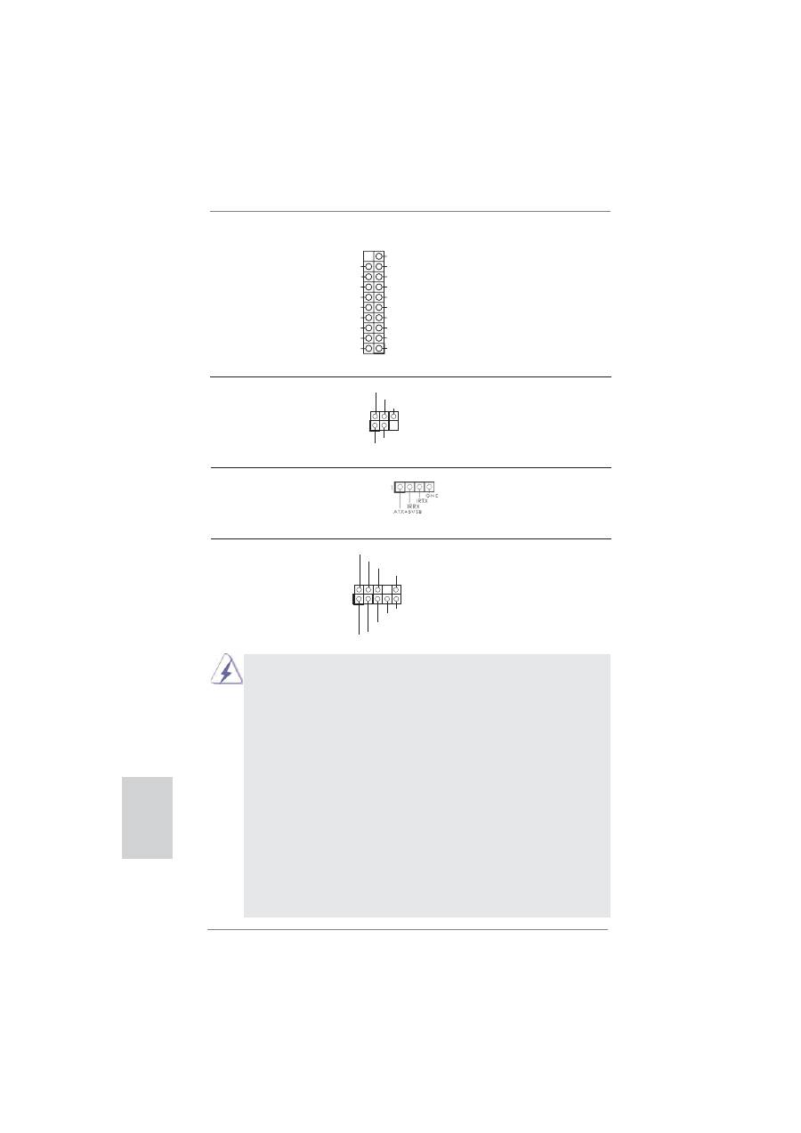
System Panel Header
This header accommodates
(9-pin PANEL1)
several system front panel
(see p.2 No. 21)
functions.
Connect the power switch, reset switch and system status indicator
on the chassis to this header according to the pin assignments below.
Note the positive and negative pins before connecting the cables.
PWRBTN (Power Switch):
Connect to the power switch on the chassis front panel. You may con-
fi
gure the way to turn off your system using the power switch.
RESET (Reset Switch):
Connect to the reset switch on the chassis front panel. Press the reset
switch to restart the computer if the computer freezes and fails to per-
form a normal restart.
PLED (System Power LED):
Connect to the power status indicator on the chassis front panel. The
LED is on when the system is operating. The LED keeps blinking
when the sys-tem is in S1 sleep state. The LED is off when the system
is in S3/S4 sleep state or powered off (S5).
HDLED (Hard Drive Activity LED):
Connect to the hard drive activity LED on the chassis front panel. The
LED is on when the hard drive is reading or writing data.
The front panel design may differ by chassis. A front panel module
mainly consists of power switch, reset switch, power LED, hard drive
activity LED, speaker and etc. When connecting your chassis front
panel module to this header, make sure the wire assignments and the
pin assign-ments are matched correctly.
28
ASRock FM2A85X Extreme4 Motherboard
English
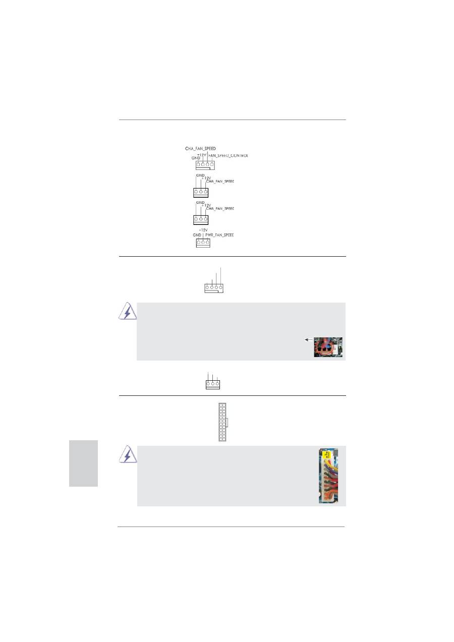
CPU Fan Connectors
Please connect the CPU fan
(4-pin CPU_FAN1)
cable to the connector and
(see p.2 No. 5)
match the black wire to the
ground
pin.
Though this motherboard provides 4-Pin CPU fan (Quiet Fan) support, the 3-Pin
CPU fan still can work successfully even without the fan speed control function.
If you plan to connect the 3-Pin CPU fan to the CPU fan connector on this
motherboard, please connect it to Pin 1-3.
ATX Power Connector
Please connect an ATX power
(24-pin ATXPWR1)
supply to this connector.
(see p.2 No. 9)
12
1
Though this motherboard provides 24-pin ATX power connector,
it can still work if you adopt a traditional 20-pin ATX power supply.
To use the 20-pin ATX power supply, please plug your power
supply along with Pin 1 and Pin 13.
(3-pin CPU_FAN2)
(see p.2 No. 6)
20-Pin ATX Power Supply Installation
Pin 1-3 Connected
3-Pin Fan Installation
12
1
24
13
24
13
GND
+12V
CPU_FAN_SPEED
FAN_SPEED_CONTROL
1 2 3 4
GND
+12V
CPU_FAN_SPEED
Chassis and Power Fan Connectors
Please connect the fan cables
(4-pin CHA_FAN1)
to the fan connectors and
(see p.2 No. 24)
match the black wire to the
ground pin. CHA_FAN1/2/3 fan
(3-pin CHA_FAN2)
speed can be controlled through
(see p.2 No. 43)
UEFI or AXTU.
(3-pin CHA_FAN3)
(see p.2 No. 44)
(3-pin PWR_FAN1)
(see p.2 No. 1)
29
ASRock FM2A85X Extreme4 Motherboard
English
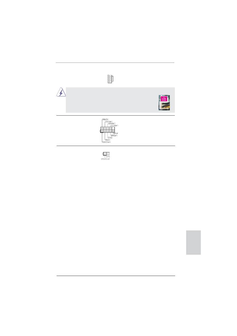
Serial port Header
This COM1 header supports a
(9-pin COM1)
serial port module.
(see p.2 No. 32)
HDMI_SPDIF Header
HDMI_SPDIF header, providing
(2-pin HDMI_SPDIF1)
SPDIF audio output to HDMI
(
see p.2 No. 33)
VGA card, allows the system to
connect HDMI Digital TV/
projector/LCD devices. Please
connect the HDMI_SPDIF
connector of HDMI VGA card to
this
header.
ATX 12V Power Connector
Please connect an ATX 12V
(8-pin ATX12V1)
power supply to this connector.
(see p.2 No. 2)
Though this motherboard provides 8-pin ATX 12V power connector, it can still work
if you adopt a traditional 4-pin ATX 12V power supply. To use the
4-pin ATX power supply, please plug your power supply along with
Pin 1 and Pin 5.
4-Pin ATX 12V Power Supply Installation
4 8
1 5
4 8
1 5
30
ASRock FM2A85X Extreme4 Motherboard
English
2.8 Smart Switches
This motherboard has three smart switches: power switch, reset switch and clear
CMOS switch, allowing users to quickly turn on/off or reset the system or clear the
CMOS values.
Power Switch
Power Switch is a smart switch,
(PWRBTN)
allowing users to quickly turn
(see p.2 No. 22)
on/off the system.
Reset Switch
Reset Switch is a smart switch,
(RSTBTN)
allowing users to quickly reset
(see p.2 No. 20)
the
system.
Clear CMOS Switch
Clear CMOS Switch is a smart
(CLRCBTN)
switch, allowing users to quickly
(see p.3 No. 14)
clear the CMOS values
31
ASRock FM2A85X Extreme4 Motherboard
English
2.9 Dr. Debug
Dr. Debug is used to provide code information, which makes troubleshooting even
easier. Please see the diagrams below for reading the Dr. Debug codes.
Status Code
Description
00
Please check if CPU is installed correctly and then clear CMOS.
0d
Problem related to memory, VGA card and other devices.
Please clear CMOS, re-install memory and VGA card, and remove other
USB, PCI devices.
01 - 54
Problem related to memory. Please re-install CPU and memory then clear
(except 0d),
CMOS.
5A- 60
If the problem still exists, please install only one memory module or try using
other memory modules.
55
Memory could not be detected. Please re-install memory and CPU.
If the problem still exists, please install only one memory module or try using
other memory modules.
61 - 91
Chipset initialization error. Please press reset or clear CMOS.
92 - 99
Problem related to PCI-E devices. Please re-install PCI-E devices or try
installing them in other slots.
If the problem still exists, please remove all PCI-E devices or try using
another VGA card.
A0 - A7
Problem related to IDE or SATA devices. Please re-install IDE and SATA
devices.
If the problem still exists, please clear CMOS and try removing all SATA
devices.
b0
Problem related to memory. Please re-install CPU and memory.
If the problem still exists, please install only one memory module or try using
other memory modules.
* For X79 models, please try installing memory to DDR3_A1, B1, C1 and D1
slots.
b4
Problem related to USB devices. Please try removing all USB devices.
b7
Problem related to memory. Please re-install CPU and memory then clear
CMOS.
If the problem still exists, please install only one memory module or try using
other memory modules.
d6
VGA could not be recognized. Please clear CMOS and try re-installing the
VGA
card.
If the problem still exists, please try installing the VGA card in other slots or
using other VGA cards.
d7
Keyboard and mouse could not be recognized. Please try re-installing
keyboard and mouse.
d8
Invalid Password.
FF
Please check if CPU is installed correctly and then clear CMOS.

32
ASRock FM2A85X Extreme4 Motherboard
English
2.10 Driver Installation Guide
To install the drivers to your system, please insert the support CD to your optical
drive
fi
rst. Then, the drivers compatible to your system can be auto-detected and
listed on the support CD driver page. Please follow the order from up to bottom side
to install those required drivers. Therefore, the drivers you install can work properly.
STEP 1: Set up UEFI.
A.
Enter UEFI SETUP UTILITY Advanced screen Storage
Con
fi
guration.
B.
Set the “SATA Mode” option to [IDE].
STEP 2: Install Windows
®
8 / 8 64-bit / 7 / 7 64-bit / Vista
TM
/ Vista
TM
64-bit OS on
your system.
Using SATA3 HDDs without NCQ and Hot Plug functions (IDE mode)
2.12 Installing Windows
®
8 / 8 64-bit / 7 / 7 64-bit / Vista
TM
/
Vista
TM
64-bit Without RAID Functions
If you want to install Windows
®
8 / 8 64-bit / 7 / 7 64-bit / Vista
TM
/ Vista
TM
64-bit on
your SATA3 HDDs without RAID functions, please follow below steps.
Using SATA3 HDDs with NCQ and Hot Plug functions (AHCI mode)
STEP 1: Set up UEFI.
A.
Enter UEFI SETUP UTILITY Advanced screen Storage
Con
fi
guration.
B.
Set the “SATA Mode” option to [AHCI].
STEP 2: Install Windows
®
8 / 8 64-bit / 7 / 7 64-bit / Vista
TM
/ Vista
TM
64-bit OS on
your system.
2.11 Installing Windows
®
8 / 8 64-bit / 7 / 7 64-bit / Vista
TM
/
Vista
TM
64-bit With RAID Functions
If you want to install Windows
®
8 / 8 64-bit / 7 / 7 64-bit / Vista
TM
/ Vista
TM
64-bit
on your SATA3 HDDs with RAID functions, please refer to the document at the
following path in the Support CD for detailed procedures:
..\ RAID Installation Guide

33
ASRock FM2A85X Extreme4 Motherboard
English
3. BIOS Information
The Flash Memory on the motherboard stores BIOS Setup Utility. When you start up
the computer, please press <F2> or <Del> during the Power-On-Self-Test (POST)
to enter BIOS Setup utility; otherwise, POST continues with its test routines. If you
wish to enter BIOS Setup after POST, please restart the system by pressing <Ctl>
+ <Alt> + <Delete>, or pressing the reset button on the system chassis. The BIOS
Setup program is designed to be user-friendly. It is a menu-driven program, which
allows you to scroll through its various sub-menus and to select among the prede-
termined choices. For the detailed information about BIOS Setup, please refer to the
User Manual (PDF
fi
le) contained in the Support CD.
4. Software Support CD information
This motherboard supports various Microsoft
®
Windows
®
operating systems: 8 /
8 64-bit / 7 / 7 64-bit / Vista
TM
/ Vista
TM
64-bit. The Support CD that came with the
motherboard contains necessary drivers and useful utilities that will enhance moth-
erboard features. To begin using the Support CD, insert the CD into your CD-ROM
drive. It will display the Main Menu automatically if “AUTORUN” is enabled in your
computer. If the Main Menu does not appear automatically, locate and double-click
on the
fi
le “ASSETUP.EXE” from the BIN folder in the Support CD to display the
menus.
34
ASRock FM2A85X Extreme4 Motherboard
1. Einführung
Wir danken Ihnen für den Kauf des ASRock
FM2A85X Extreme4
Motherboard, ein
zuverlässiges Produkt, welches unter den ständigen, strengen Qualitätskontrollen
von ASRock gefertigt wurde. Es bietet Ihnen exzellente Leistung und robustes De-
sign, gemäß der Verp
fl
ichtung von ASRock zu Qualität und Halbarkeit. Diese Sch-
nellinstallationsanleitung führt in das Motherboard und die schrittweise Installation
ein. Details über das Motherboard
fi
nden Sie in der Bedienungsanleitung auf der
Support-CD.
Da sich Motherboard-Spezi
fi
kationen und BIOS-Software verändern
können, kann der Inhalt dieses Handbuches ebenfalls jederzeit geändert
werden. Für den Fall, dass sich Änderungen an diesem Handbuch
ergeben, wird eine neue Version auf der ASRock-Website, ohne weitere
Ankündigung, verfügbar sein. Die neuesten Gra
fi
kkarten und unterstützten
CPUs sind auch auf der ASRock-Website aufgelistet.
ASRock-Website: http://www.asrock.com
Wenn Sie technische Unterstützung zu Ihrem Motherboard oder spezi
fi
sche
Informationen zu Ihrem Modell benötigen, besuchen Sie bitte unsere
Webseite:
www.asrock.com/support/index.asp
1.1 Kartoninhalt
ASRock
FM2A85X Extreme4
Motherboard (ATX-Formfaktor)
ASRock
FM2A85X Extreme4
Schnellinstallationsanleitung
ASRock
FM2A85X Extreme4
Support-CD
Vier Serial ATA (SATA) -Datenkabel (optional)
Ein I/O Shield
ASRock erinnert...
Zur besseren Leistung unter Windows
®
8 / 8 64 Bit / 7 / 7 64 Bit / Vista
TM
/ Vista
TM
64 Bit empfehlen wir, die Speicherkon
fi
guration im BIOS auf den
AHCI-Modus einzustellen. Hinweise zu den BIOS-Einstellungen
fi
nden
Sie in der Bedienungsanleitung auf der mitgelieferten CD.
Deutsch
35
ASRock FM2A85X Extreme4 Motherboard
Deutsch
1.2 Spezi
fi
kationen
Plattform
-
ATX-Formfaktor
- Alle Feste Kondensatordesign (100 % hochwertige
japanische Fertigung leitfähiger Polymerkondensatoren)
CPU
- Unterstützt Sockel-FM2-100-W-Prozessoren
- 4 + 2-Stromphasendesign
- Unterstützt Cool ‘n’ Quiet
TM
-Technologie von AMD
-
UMI-Link-GEN2
Chipsatz
- AMD A85X (Hudson-D4)
Speicher
- Unterstützung von Dual-Kanal-Speichertechnologie
- 4 x Steckplätze für DDR3
- Unterstützt DDR3 2600+(OC)/2400(OC)/2133(OC)/1866/
1600/1333/1066/800 non-ECC, ungepufferter Speicher
- Max. Kapazität des Systemspeichers: 64GB
- Unterstützt Intel
®
Extreme Memory Pro
fi
le (XMP)1.3/1.2
- Unterstützt AMD Memory Pro
fi
le (AMP)
Erweiterungs-
- 2 x PCI-Express-2.0-x16-Steckplätze
steckplätze
(PCIE2: x16-Modus; PCIE4: x4-Modus)
- 2 x PCI Express 2.0 x1-Steckplätze
- 3 x PCI -Steckplätze
- Unterstützt AMD Quad CrossFireX
TM
, CrossFireX
TM
und
duale Gra
fi
kkarten
Onboard-VGA
- AMD Radeon HD 7000-Gra
fi
k
- DirectX 11, Pixel Shader 5.0
- Maximal gemeinsam genutzter Speicher 2GB
- Drei VGA-Ausgangsoptionen: D-Sub, DVI-D sowie HDMI
- Unterstützt HDMI 1.4a mit einer maximalen Au
fl
ösung von
1920 x 1200 bei 60 Hz
- Unterstützt Dual-link DVI mit einer maximalen Au
fl
ösung von
2560 x 1600 bei 75 Hz
- Unterstützt D-Sub mit einer maximalen Au
fl
ösung von
1920 x 1600 bei 60 Hz
- Unterstützt Auto Lip Sync, Deep Color (12bpc), xvYCC und
HBR (High Bit Rate-Audio) mit HDMI (kompatibler HDMI-
Bildschirm erforderlich)
- Unterstützt stereoskopisches 3D per Blu-ray mit HDMI 1.4a
- Unterstützt AMD Steady Video
TM
2.0: Neuartige Funktion der
Videonachbearbeitung für automatische Reduzierung von
Bildschwankungen bei Heim-/Online-Videos
- Unterstützt HDCP-Funktion mit DVI- und HDMI-Ports
36
ASRock FM2A85X Extreme4 Motherboard
Deutsch
- Unterstutzt 1080p Blu-ray (BD) / HD-DVD-Wiedergabe
mit DVI- und HDMI-Ports
Audio
-
7.1
CH HD Audio mit dem Inhalt Schutz
(Realtek ALC892 Audio Codec)
- Premium Blu-ray-Audio-Unterstützung
- Unterstützt THX TruStudio
TM
LAN
- PCIE x1 Gigabit LAN 10/100/1000 Mb/s
- Realtek RTL8111E
- Unterstützt Wake-On-LAN
- Unterstützt LAN-Kabelerkennung
- Unterstützt energieef
fi
zientes Ethernet 802.3az
- Unterstützt PXE
E/A-Anschlüsse
I/O Panel
an der
- 1 x PS/2-Maus/Tastaturanschluss
Rückseite
- 1 x D-Sub port
- 1 x DVI-D port
- 1 x HDMI port
- 1 x optischer SPDIF-Ausgang
- 2 x Standard-USB 2.0-Anschlüsse
- 1 x eSATA3-Anschluss
- 6 x Standard-USB 3.0-Anschlüsse
- 1 x RJ-45 LAN Port mit LED (ACT/LINK LED und SPEED
LED)
- 1 x CMOS löschen-Schalter
- HD Audiobuchse: Lautsprecher hinten / Mitte/Bass /
Audioeingang / Lautsprecher vorne / Mikrofon
SATA3
- 7 x SATA 3-Anschluss mit 6,0 Gb/s, unterstützt RAID-
(RAID 0, RAID 1, RAID 5 und RAID 10), NCQ-, AHCI- und
„Hot Plugging“-Funktionen
USB3.0
- 2 x USB 3.0-Ports an der Rückseite durch AMD A85X
(Hudson-D4), unterstützt USB 1.1/2.0/3.0 mit bis zu 5 Gb/s
- 4 x USB 3.0-Ports an der Rückseite durch Etron EJ188,
unterstützt USB 1.1/2.0/3.0 mit bis zu 5 Gb/s
- 1 x USB 3.0-Header (unterstützt zwei USB 3.0-Ports) an der
Vorderseite durch AMD A85X (Hudson-D4), unterstützt
USB 1.1/2.0/3.0 mit bis zu 5 Gb/s
Anschlüsse
- 7 x SATA3 6,0 GB/s-Anschlüsse
- 1 x Infrarot-Modul-Header
- 1 x Consumer Infrarot-Modul-Header
- 1 x COM-Anschluss-Header
- 1 x HDMI_SPDIF-Anschluss
- 1 x Betriebs-LED-Header
37
ASRock FM2A85X Extreme4 Motherboard
Deutsch
- 2 x CPUlüfter-Anschluss (1 x 4-pin, 1 x 3-pin)
- 3 x Gehäuselüfter-Anschluss (1 x 4-pin, 2 x 3-pin)
- 1 x Stromlüfter-Anschluss (3-pin)
-
24-pin
ATX-Netz-Header
- 8-pin anschluss für 12V-ATX-Netzteil
- Anschluss für Audio auf der Gehäusevorderseite
- 3 x USB 2.0-Anschlüsse (Unterstützung 6 zusätzlicher
USB 2.0-Anschlüsse)
- 1 x USB 3.0-Anschlüsse (Unterstützung 2 zusätzlicher
USB 3.0-Anschlüsse)
- 1 x Dr. Debug (Debug-LED mit 7 Segmenten)
- 1 x Netzschalter mit LED
- 1 x Rücksetzschalter (Reset) mit LED
BIOS
- 64Mb AMIs Legal BIOS UEFI mit GUI-Unterstützung
- Unterstützung für “Plug and Play”
-
ACPI
1.1-Weckfunktionen
-
JumperFree-Modus
- SMBIOS 2.3.1
- DRAM, APU PCIE VDDP, CPU und CPU NB/GFX
Stromspannung Multianpassung
Support-CD
- Treiber, Dienstprogramme, Antivirussoftware
(Probeversion), CyberLink MediaEspresso 6.5-Testversion,
Google Chrome Browser und Toolbar
Hardware Monitor
-
CPU-Temperatursensor
-
Motherboardtemperaturerkennung
- Drehzahlmessung für CPU/Gehäuse/Stromlüfter
- Geräuscharmer CPUlüfter
-
Mehrstu
fi
ge Geschwindigkeitsteuerung für CPU-/
Gehäuselüfter
- Spannungsüberwachung: +12V, +5V, +3.3V, Vcore
Betriebssysteme
- Unterstützt Microsoft
®
Windows
®
8 / 8 64-Bit / 7 / 7 64-Bit /
Vista
TM
/ Vista
TM
64-Bit
Zerti
fi
zierungen
- FCC, CE, WHQL
- Gemäß Ökodesign-Richtlinie (ErP/EuP) (Stromversorgung
gemäß Ökodesign-Richtlinie (ErP/EuP) erforderlich)
* Für die ausführliche Produktinformation, besuchen Sie bitte unsere Website:
http://www.asrock.com
38
ASRock FM2A85X Extreme4 Motherboard
Deutsch
1.3 Einstellung der Jumper
Die Abbildung verdeutlicht, wie Jumper
gesetzt werden. Werden Pins durch
Jumperkappen verdeckt, ist der Jumper
“Gebrückt”. Werden keine Pins durch
Jumperkappen verdeckt, ist der Jumper
“Offen”. Die Abbildung zeigt einen 3-Pin
Jumper dessen Pin1 und Pin2 “Ge-
brückt” sind, bzw. es be
fi
ndet sich eine
Jumper-Kappe auf diesen beiden Pins.
Jumper Einstellun
Beschreibung
CMOS löschen
(CLRCMOS1, 3-Pin jumper)
(siehe S.2, No. 27)
Hinweis:
CLRCMOS1 ermöglicht Ihnen die Löschung der Daten im CMOS. Zum
Löschen und Zurücksetzen der Systemparameter auf die Standardeinrichtung
schalten Sie den Computer bitte aus und trennen das Netzkabel von der
Stromversorgung. Warten Sie 15 Sekunden, schließen Sie dann Pin2 und
Pin3 am CLRCMOS1 über einen Jumper fünf Sekunden lang kurz. Sie
sollten das CMOS allerdings nicht direkt nach der BIOS-Aktualisierung
löschen. Wenn Sie das CMOS nach Abschluss der BIOS-Aktualisierung
löschen müssen, fahren Sie zuerst das System hoch. Fahren Sie es dann
vor der CMOS-Löschung herunter. Bitte beachten Sie, dass Kennwort,
Datum, Uhrzeit, benutzerde
fi
niertes Pro
fi
l, 1394 GUID und MAC-Adresse
nur gelöscht werden, wenn die CMOS-Batterie entfernt wird.
CMOS
löschen
Default-
Einstellung
Der CMOS löschen-Schalter hat dieselbe Funktion wie der CMOS
löschen-Jumper.
39
ASRock FM2A85X Extreme4 Motherboard
Deutsch
USB 2.0-Header
Zusätzlich zu den zwei
(9-pol. USB3_4)
üblichen USB 2.0-Ports an den
(siehe S.2 - No. 30)
I/O-Anschlüssen
be
fi
nden sich
drei USB 2.0-
Anschlussleisten am
(9-pol. USB5_6)
Motherboard. Pro USB 2.0-
(siehe S.2 - No. 29)
Anschlussleiste werden zwei
USB 2.0-Ports unterstützt.
(9-pol. USB7_8)
(siehe S.2 - No. 28)
Seriell-ATA3-Anschlüsse
Diese sieben Serial ATA3-
(SATA3_1: siehe S.2 - No. 13)
(SATA3-)Verbínder
(SATA3_2: siehe S.2 - No. 12)
unterstützten SATA-Datenkabel
(SATA3_3: siehe S.2 - No. 14)
für interne
(SATA3_4: siehe S.2 - No. 15)
Massenspeichergeräte. Die
(SATA3_5: siehe S.2 - No. 19)
aktuelle SATA3- Schnittstelle
(SATA3_6: siehe S.2 - No. 16)
ermöglicht eine
(SATA3_7: siehe S.2 - No. 17)
Datenübertragungsrate
bis
6,0 Gb/s.
Serial ATA- (SATA-)
SJedes Ende des SATA
Datenkabel
Datenkabels kann an die
(Option)
SATA3 Festplatte oder das
SATA3 Verbindungsstück auf
dieser Hauptplatine
angeschlossen
werden.
1.4 Anschlüsse
Anschlussleisten sind KEINE Jumper. Setzen Sie KEINE Jumperkappen
auf die Pins der Anschlussleisten. Wenn Sie die Jumperkappen auf die
Anschlüsse setzen, wird das Motherboard permanent beschädigt!
Anschluss Beschreibung
1
USB_PWR
P-4
P+4
USB_PWR
P-3
P+3
GND
GND
DUMMY
1
USB_PWR
P-6
P+6
USB_PWR
P-5
P+5
GND
GND
DUMMY
1
USB_PWR
P-8
P+8
USB_PWR
P-7
P+7
GND
GND
DUMMY
SA
TA3_6 SA
TA3_3 SA
TA3_1
SA
TA3_7 SA
TA3_4 SA
TA3_2
SATA3_5
40
ASRock FM2A85X Extreme4 Motherboard
Deutsch
Infrarot-Modul-Header
Dieser Header unterstützt ein
(5-pin IR1)
optionales, drahtloses Sende-
(siehe S.2 - No. 25)
und
Empfangs-Infrarotmodul.
Anschluss für Audio auf
Dieses Interface zu einem
der Gehäusevorderseite
Audio-Panel auf der Vorder
(9-Pin HD_AUDIO1)
seite Ihres Gehäuses,
(siehe S.2 - No. 34)
ermöglicht Ihnen eine bequeme
Anschlussmöglichkeit und
Kontrolle
über
Audio-Geräte.
Consumer Infrared-Modul-Header
Dieser Header kann zum
(4-pin CIR1)
Anschließen
Remote-
(siehe S.2 - No. 31)
Empfänger.
1
IRTX
+5VSB
DUMMY
IRRX
GND
J_SENSE
OUT2_L
1
MIC_RET
PRESENCE#
GND
OUT2_R
MIC2_R
MIC2_L
OUT_RET
IntA_P8_D+
DUMMY
IntA_P8_D-
GND
IntA_P8_SSTX+
GND
IntA_P8_SSTX-
IntA_P8_SSRX+
IntA_P8_SSRX-
Vbus
Vbus
Vbus
IntA_P7_SSRX-
IntA_P7_SSRX+
GND
IntA_P7_SSTX-
IntA_P7_SSTX+
GND
IntA_P7_D-
IntA_P7_D+
USB 3.0-Header
Neben sechs Standard-USB
(19-pol. USB3_7_8)
3.0-Ports am E/A-Panel
(siehe S.2 - No. 10)
be
fi
ndet sich ein USB 3.0-
Header an diesem
Motherboard. Dieser USB 3.0-
Header kann zwei USB 3.0-
Ports
unterstützen.
1. High De
fi
nition Audio unterstützt Jack Sensing (automatische Erkennung
falsch angeschlossener Geräte), wobei jedoch die Bildschirmverdrahtung
am Gehäuse HDA unterstützen muss, um richtig zu funktionieren.
Beachten Sie bei der Installation im System die Anweisungen in unserem
Handbuch und im Gehäusehandbuch.
2. Wenn Sie die AC’97-Audioleiste verwenden, installieren Sie diese wie
nachstehend beschrieben an der Front-Audioanschlussleiste:
A. Schließen Sie Mic_IN (MIC) an MIC2_L an.
B. Schließen Sie Audio_R (RIN) an OUT2_R und Audio_L (LIN) an OUT2_L an.
C. Schließen Sie Ground (GND) an Ground (GND) an.
D. MIC_RET und OUT_RET sind nur für den HD-Audioanschluss gedacht. Diese
Anschlüsse müssen nicht an die AC’97-Audioleiste angeschlossen werden.
E. So aktivieren Sie das Mikrofon an der Vorderseite.
Bei den Betriebssystemen Windows
®
8 / 8 64 Bit / 7 / 7 64 Bit / Vista
TM
/ Vista
TM
64 Bit:
Wählen Sie im Realtek-Bedienfeld die „FrontMic“ (Vorderes Mikrofon)-
Registerkarte. Passen Sie die „Recording Volume“ (Aufnahmelautstärke)
an.
