ASRock FM2A75 Pro4-M – страница 2
Инструкция к Материнской Плате ASRock FM2A75 Pro4-M
TM
TM
2.5 CrossFireX
and Quad CrossFireX
Operation Guide
TM
TM
This motherboard supports CrossFireX
and Quad CrossFireX
.
TM
CrossFireX
technology offers the most advantageous means available
of combining multiple high performance Graphics Processing Units (GPU)
in a single PC. Combining a range of different operating modes with
intelligent software design and an innovative interconnect mechanism,
TM
CrossFireX
enables the highest possible level of performance and image
TM
quality in any 3D application. Currently CrossFireX
feature is supported
®
TM
TM
with Windows
XP with Service Pack 2 / Vista
/ 7 OS. Quad CrossFireX
®
TM
feature are supported with Windows
Vista
/ 7 OS only. Please check
TM
AMD website for AMD CrossFireX
driver updates.
1. If a customer incorrectly congures their system they will not see
TM
TM
the performance benefits of CrossFireX
. All three CrossFireX
TM
TM
components, a CrossFireX
Ready graphics card, a CrossFireX
TM
Ready motherboard and a CrossFireX
Edition co-processor
graphics card, must be installed correctly to benefit from the
TM
CrossFireX
multi-GPU platform.
TM
2. If you pair a 12-pipe CrossFireX
Edition card with a 16-pipe card,
TM
both cards will operate as 12-pipe cards while in CrossFireX
mode.
2.5.1 Graphics Card Setup
TM
Different CrossFireX
cards may require different methods to enable
TM
TM
CrossFireX
feature. For other CrossFireX
cards that AMD has re-
leased or will release in the future, please refer to AMD graphics card
manuals for detailed installation guide.
English
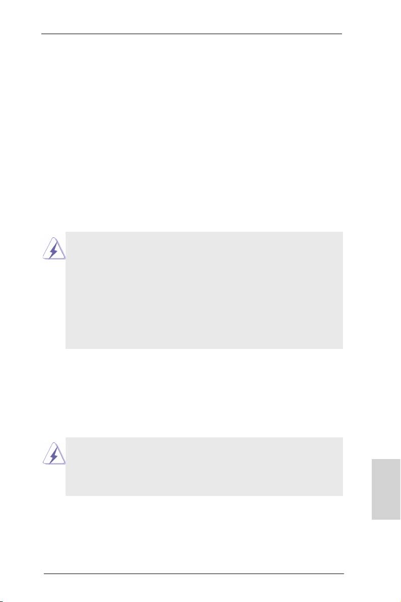
Step 1. Insert one Radeon graphics card into PCIE1 slot and the other
Radeon graphics card to PCIE3 slot. Make sure that the cards are
properly seated on the slots.
21
ASRock FM2A75 Pro4-M Motherboard
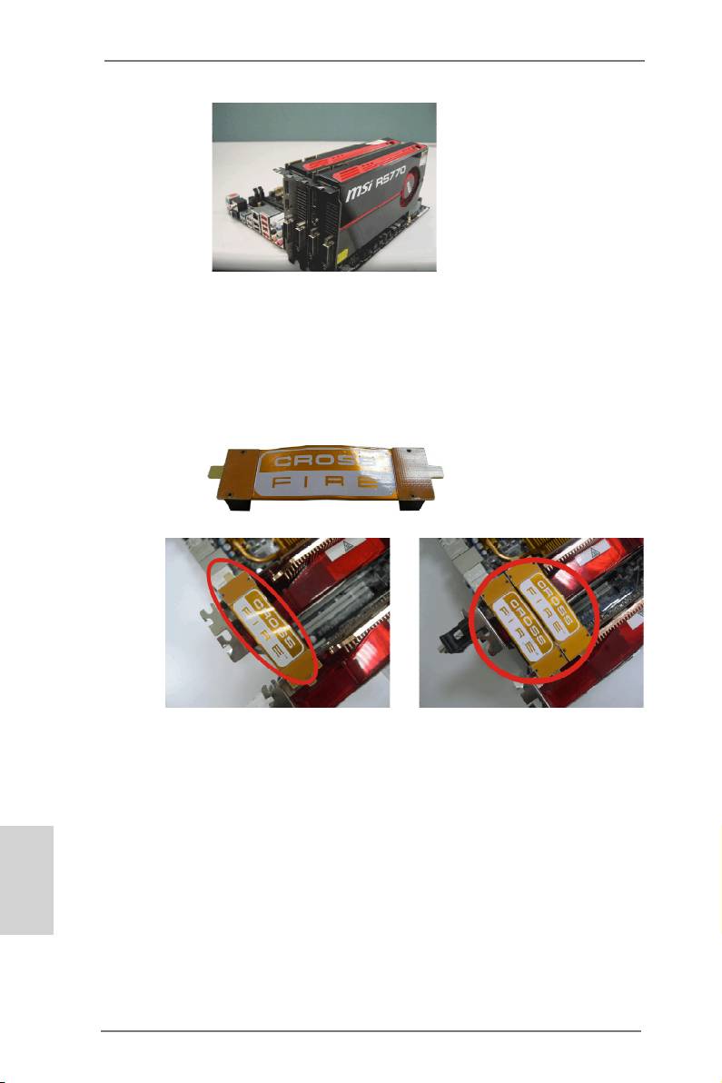
Step 2. Connect two Radeon graphics cards by installing a CrossFire
Bridge on the top of the Radeon graphics cards. (The Cross-
Fire Bridge is provided with the graphics card you purchase, not
bundled with this motherboard. Please refer to your graphics card
vendor for details.)
CrossFire Bridge
or
Step 3. Connect the DVI monitor cable to the DVI connector on the Rad-
eon graphics card on PCIE1 slot. (You may use the DVI to D-Sub
adapter to convert the DVI connector to D-Sub interface, and then
connect the D-Sub monitor cable to the DVI to D-Sub adapter.)
English
22
ASRock FM2A75 Pro4-M Motherboard
2.5.2 Driver Installation and Setup
Step 1. Power on your computer and boot into OS.
Step 2. Remove the AMD driver if you have any VGA driver installed in
your system.
The Catalyst Uninstaller is an optional download. We recommend using
this utility to uninstall any previously installed Catalyst drivers prior to in-
stallation. Please check AMD’s website for AMD driver updates.
Step 3. Install the required drivers to your system.
®
For Windows
XP OS:
®
A. AMD recommends Windows
XP Service Pack 2 or higher to
®
be installed (If you have Windows
XP Service Pack 2 or higher
installed in your system, there is no need to download it again):
http://www.microsoft.com/windowsxp/sp2/default.mspx
B. You must have Microsoft .NET Framework installed prior to
downloading and installing the CATALYST Control Center.
Please check Microsoft website for details.
®
TM
For Windows
7 / Vista
OS:
Install the CATALYST Control Center. Please check AMD’s web-
site for details.
Step 4. Restart your computer.
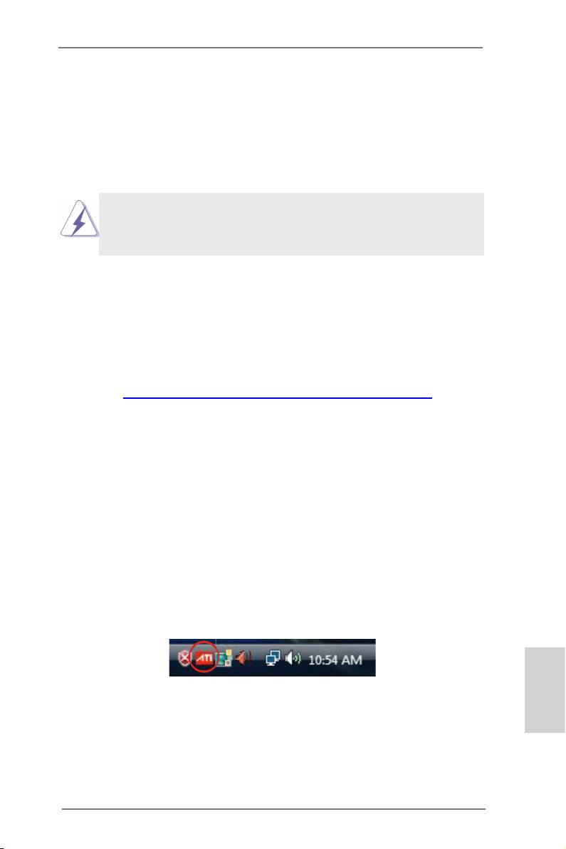
Step 5. Install the VGA card drivers to your system, and restart your com-
puter. Then you will nd “AMD Catalyst Control Center” on your
®
Windows
taskbar.
AMD Catalyst Control Center
English
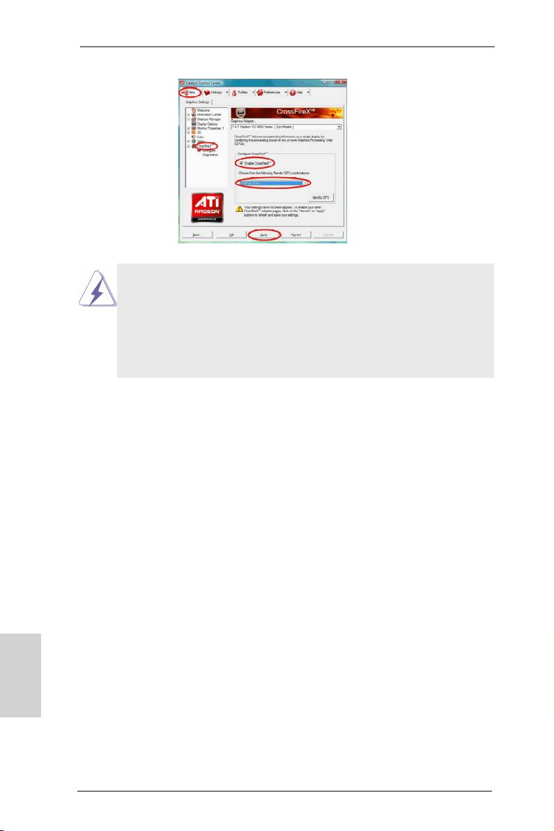
Step 6. Double-click “AMD Catalyst Control Center”. Click “View”, select
TM
TM
“CrossFireX
”, and then check the item “Enable CrossFireX
”.
Select “2 GPUs” and click “Apply” (if you install two Radeon
graphics cards).
23
ASRock FM2A75 Pro4-M Motherboard
TM
Although you have selected the option “Enable CrossFire
”, the Cross-
TM
FireX
function may not work actually. Your computer will automatically
reboot. After restarting your computer, please conrm whether the option
TM
“Enable CrossFire
” in “AMD Catalyst Control Center” is selected or not;
if not, please select it again, and then you are able to enjoy the benet of
TM
CrossFireX
feature.
TM
Step 7. You can freely enjoy the benet of CrossFireX
or Quad CrossFi-
TM
reX
feature.
TM
* CrossFireX
appearing here is a registered trademark of AMD Technologies Inc.,
and is used only for identication or explanation and to the owners’ benet,
without intent to infringe.
TM
* For further information of AMD CrossFireX
technology, please check AMD’s
website for updates and details.
English
24
ASRock FM2A75 Pro4-M Motherboard
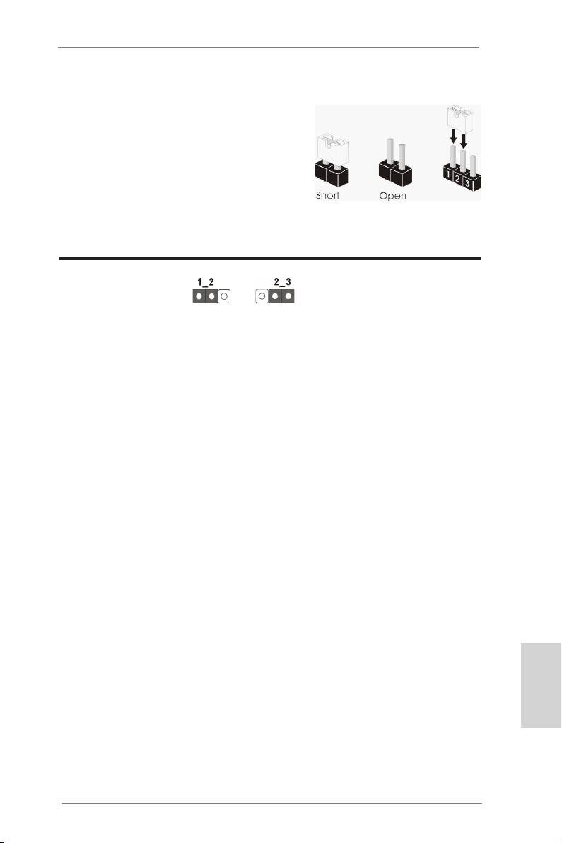
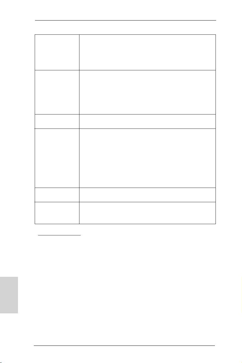
2.6 Jumpers Setup
The illustration shows how jumpers are
setup. When the jumper cap is placed on
pins, the jumper is “Short”. If no jumper cap
is placed on pins, the jumper is “Open”. The
illustration shows a 3-pin jumper whose
pin1 and pin2 are “Short” when jumper cap
is placed on these 2 pins.
Clear CMOS Jumper
(CLRCMOS1)
Clear CMOSDefault
(see p.2, No. 23)
CLRCMOS1 allows you to clear the data in CMOS. To clear and reset
the system parameters to default setup, please turn off the computer and
unplug the power cord from the power supply. After waiting for 15 seconds,
use a jumper cap to short pin2 and pin3 on CLRCMOS1 for 5 seconds.
However, please do not clear the CMOS right after you update the BIOS.
If you need to clear the CMOS when you just nish updating the BIOS,
you must boot up the system rst, and then shut it down before you do the
clear-CMOS action. Please be noted that the password, date, time, user
default prole, 1394 GUID and MAC address will be cleared only if the
CMOS battery is removed.
English
25
ASRock FM2A75 Pro4-M Motherboard
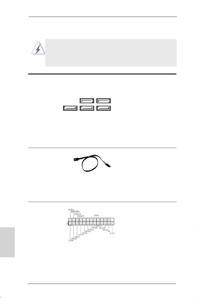
2.7 Onboard Headers and Connectors
Onboard headers and connectors are NOT jumpers. Do NOT
place jumper caps over these headers and connectors. Plac-
ing jumper caps over the headers and connectors will cause
permanent damage to the motherboard!
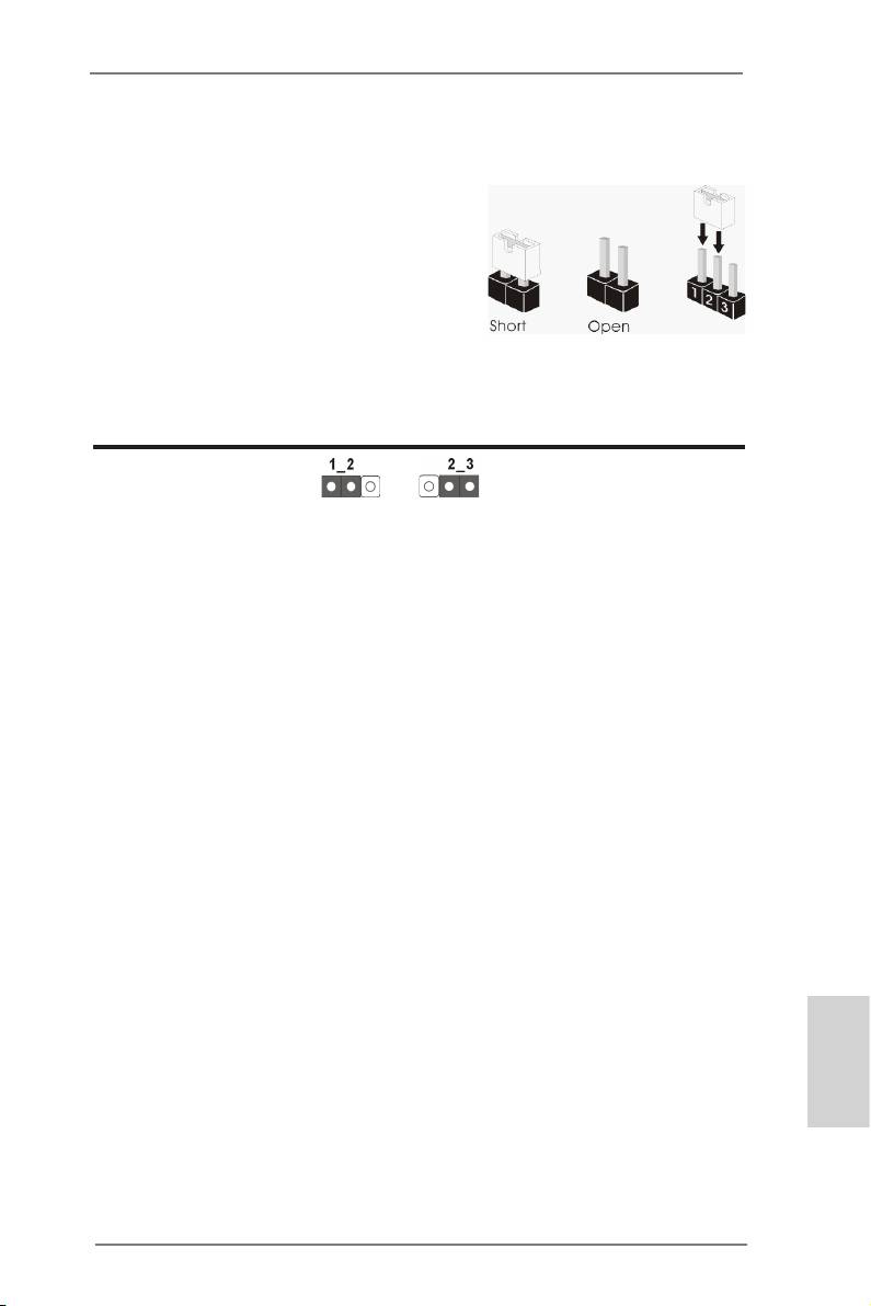
Serial ATA3 Connectors
These ve Serial ATA3
(SATA3_1:
(SATA3) connectors sup-
SATA3_5 SATA3_4
see p.2, No. 16)
port SATA data cables for
(SATA3_2:
internal storage devices.
see p.2, No. 17)
(SATA3_3:
The current SATA3 interface
SATA3_3 SATA3_2 SATA3_1
see p.2, No. 18)
allows up to 6.0 Gb/s data
(SATA3_4:
transfer rate.
see p.2, No. 15)
(SATA3_5:
see p.2, No. 14)
Serial ATA (SATA)
Either end of the SATA data
Data Cable
cable can be connected to
(Optional)
SATA / SATA2 / SATA3 hard
disks or the SATA2 / SATA3
connectors on this mother-
board.
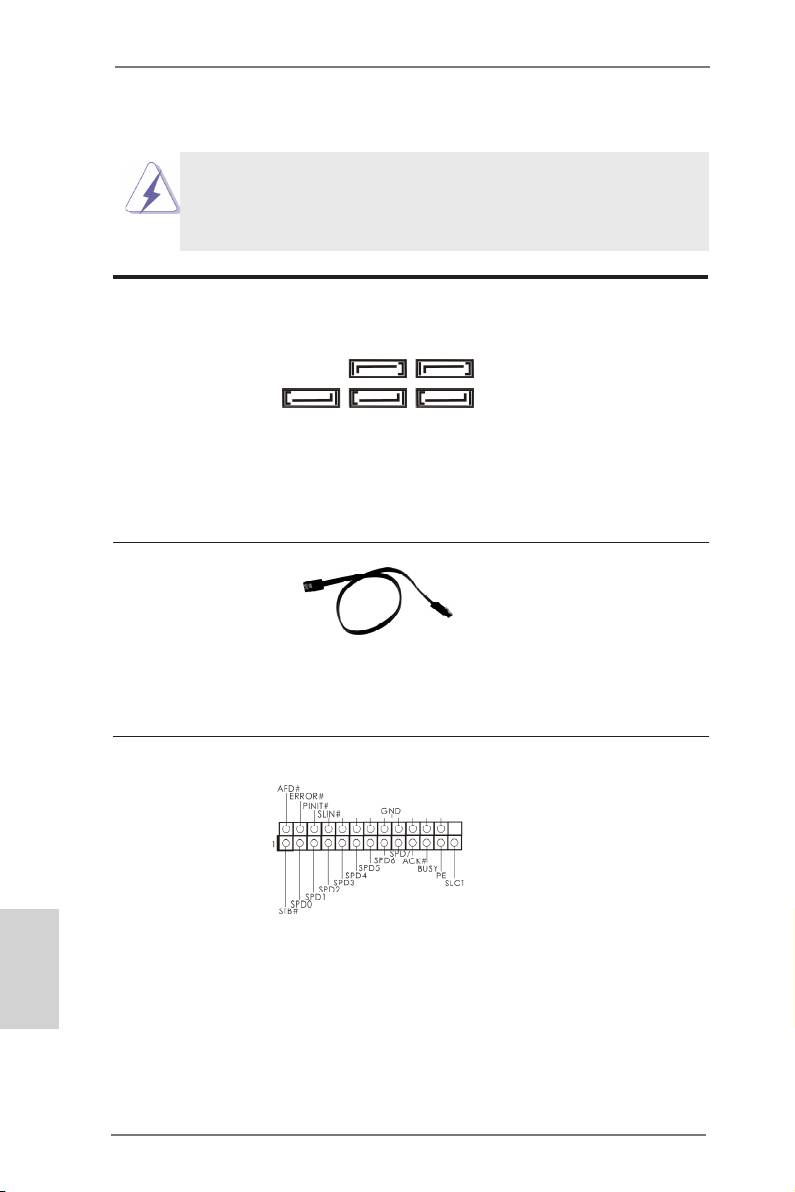
Print Port Header
This is an interface for print
(25-pin LPT1)
port cables that allows con-
(see p.2, No. 27)
venient connection of printer
English
devices.
26
ASRock FM2A75 Pro4-M Motherboard
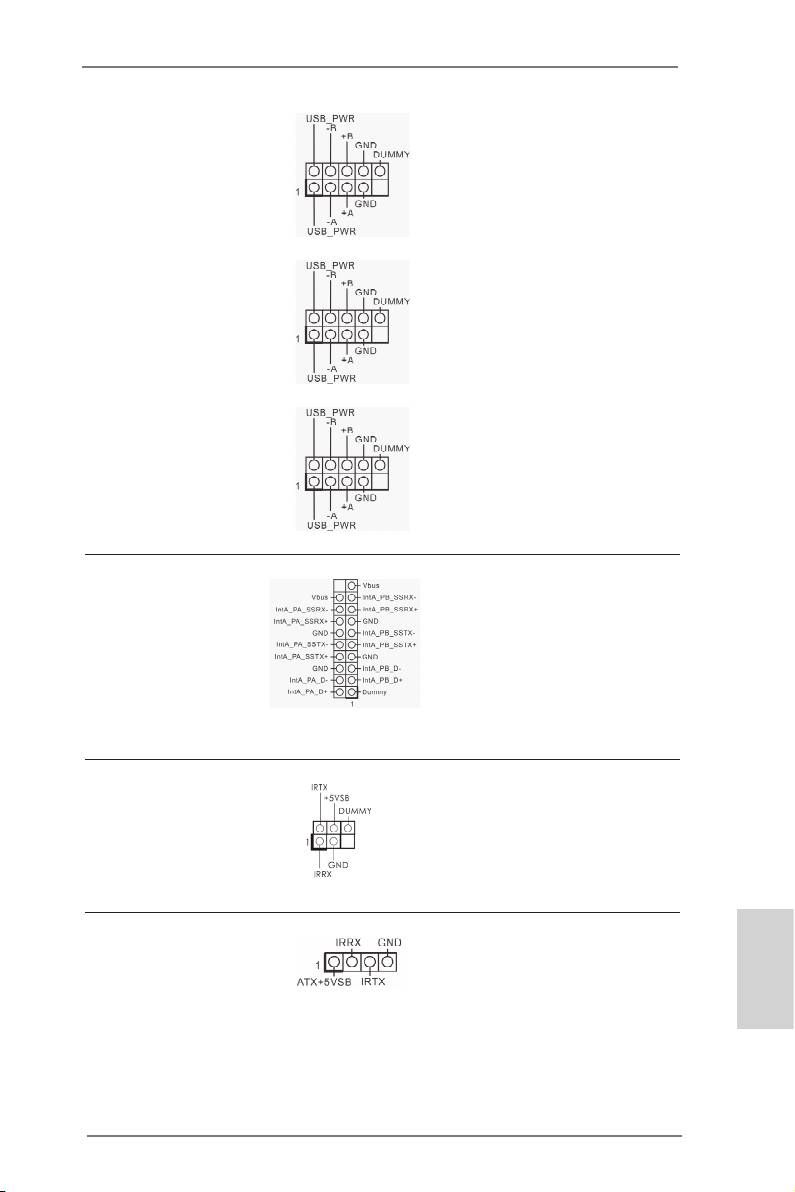
USB 2.0 Headers
Besides four default USB 2.0
and Ports
ports on the I/O panel, there
(9-pin USB5_6)
are three USB 2.0 headers
(see p.2, No. 22)
on this motherboard. Each
USB 2.0 header can support
two USB 2.0 ports.
(9-pin USB7_8)
(see p.2, No. 24)
(9-pin USB9_10)
(see p.2, No. 26)
USB 3.0 Header
Besides two default USB 3.0
(19-pin USB3_3_4)
ports on the I/O panel, there
(see p.2, No. 10)
is one USB 3.0 header on
this motherboard. Each USB
3.0 header can support two
USB 3.0 ports.
Infrared Module Header
This header supports an
(5-pin IR1)
optional wireless transmit-
(see p.2, No. 29)
ting and receiving infrared
module.
Consumer Infrared
This header can be used
Module Header
to connect the remote
English
(4-pin CIR1)
controller receiver.
(see p.2, No. 25)
27
ASRock FM2A75 Pro4-M Motherboard
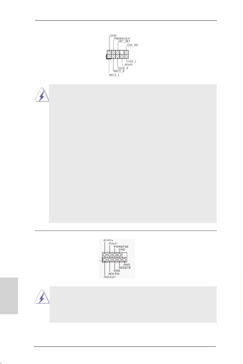
Front Panel Audio Header
This is an interface for the
(9-pin HD_AUDIO1)
front panel audio cable that
(see p.2, No. 30)
allows convenient connec-
tion and control of audio
devices.
1. High Denition Audio supports Jack Sensing, but the panel
wire on the chassis must support HDA to function correctly.
Please follow the instructions in our manual and chassis
manual to install your system.
2. If you use an AC’97 audio panel, please install it to the front
panel audio header by the steps below:
A. Connect Mic_IN (MIC) to MIC2_L.
B. Connect Audio_R (RIN) to OUT2_R and Audio_L (LIN) to
OUT2_L.
C. Connect Ground (GND) to Ground (GND).
D. MIC_RET and OUT_RET are for HD audio panel only. You
don’t need to connect them for AC’97 audio panel.
E. To activate the front mic.
®
For Windows
XP OS:
Select “Mixer”. Select “Recorder”. Then click “FrontMic”.
®
TM
TM
For Windows
7 / 7 64-bit / Vista
/ Vista
64-bit OS:
Go to the "FrontMic" Tab in the Realtek Control panel.
Adjust “Recording Volume”.
System Panel Header
This header accommodates
(9-pin PANEL1)
several system front panel
(see p.2, No. 21)
functions.
English
Connect the power switch, reset switch and system status indica-
tor on the chassis to this header according to the pin assignments
below. Note the positive and negative pins before connecting the
cables.
28
ASRock FM2A75 Pro4-M Motherboard
PWRBTN (Power Switch):
Connect to the power switch on the chassis front panel. You may
congure the way to turn off your system using the power switch.
RESET (Reset Switch):
Connect to the reset switch on the chassis front panel. Press the
reset switch to restart the computer if the computer freezes and
fails to perform a normal restart.
PLED (System Power LED):
Connect to the power status indicator on the chassis front panel.
The LED is on when the system is operating. The LED keeps
blinking when the sys-tem is in S1/S3 sleep state. The LED is off
when the system is in S4 sleep state or powered off (S5).
HDLED (Hard Drive Activity LED):
Connect to the hard drive activity LED on the chassis front panel.
The LED is on when the hard drive is reading or writing data.
The front panel design may differ by chassis. A front panel mod-
ule mainly consists of power switch, reset switch, power LED,
hard drive activity LED, speaker and etc. When connecting your
chassis front panel module to this header, make sure the wire as-
signments and the pin assignments are matched correctly.
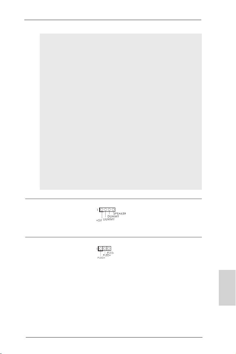
Chassis Speaker Header
Please connect the chassis
(4-pin SPEAKER1)
speaker to this header.
(see p.2, No. 19)
Power LED Header
Please connect the chassis
(3-pin PLED1)
power LED to this header
(see p.2, No. 20)
to indicate system power
status. The LED is on when
the system is operating. The
LED keeps blinking in S1
English
state. The LED is off in S3/
S4 state or S5 state (power
off).
29
ASRock FM2A75 Pro4-M Motherboard
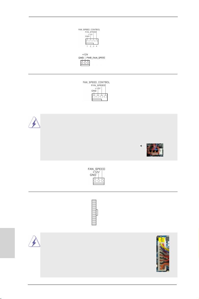
Chassis and Power
Please connect the fan
Fan Connectors
cables to the fan connectors
(4-pin CHA_FAN1)
and match the black wire to
(see p.2, No. 12)
the ground pin.
(4-pin PWR_FAN1)
(see p.2, No. 1)
CPU Fan Connectors
Please connect the CPU fan
(4-pin CPU_FAN1)
cable to the connector and
(see p.2, No. 5)
match the black wire to the
ground pin.
Though this motherboard provides a 4-Pin CPU fan (Quiet Fan)
connector, 3-Pin CPU fans can still work successfully even with-
out the fan speed control function. If you plan to connect a 3-Pin
CPU fan to the CPU fan connector on this motherboard, please
connect it to Pin 1-3.
Pin 1-3 Connected
3-Pin Fan Installation
(3-pin CPU_FAN2)
(see p.2, No. 6)
12
24
ATX Power Connector
Please connect an ATX pow-
(24-pin ATXPWR1)
er supply to this connector.
(see p.2, No. 9)
1
13
English
Though this motherboard provides a 24-pin ATX
12
24
power connector, it can still work if you adopt a
traditional 20-pin ATX power supply. To use a 20-
pin ATX power supply, please plug your power
supply along Pin 1 and Pin 13.
1
13
20-Pin ATX Power Supply Installation
30
ASRock FM2A75 Pro4-M Motherboard
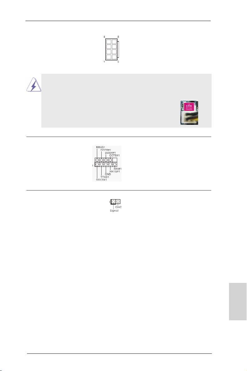
ATX 12V Power
Please connect an ATX 12V
Connector
power supply to this connec-
(8-pin ATX12V1)
tor.
(see p.2, No. 2)
Though this motherboard provides an 8-pin ATX 12V power con-
nector, it can still work if you adopt a traditional 4-pin ATX 12V
power supply. To use a 4-pin ATX power supply, please plug your
power supply along Pin 1 and Pin 5.
4 8
4-Pin ATX 12V Power Supply Installation
1 5
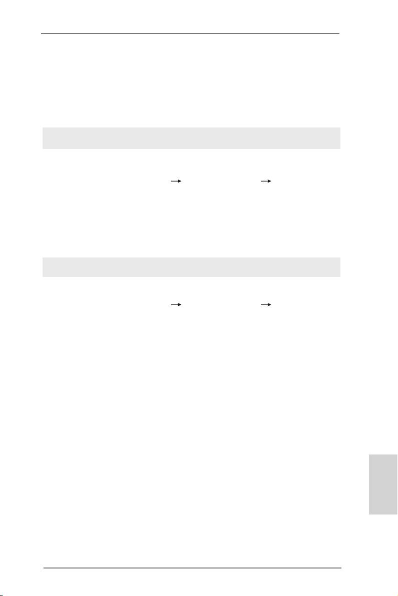
Serial port Header
This COM1 header supports
(9-pin COM1)
a serial port module.
(see p.2, No. 28)
Chassis Intrusion Header
This motherboard supports
(2-pin CI1)
CASE OPEN detection
(see p.2, No. 33)
which detects whether the
chassis cover has been re-
moved. This feature requires
a chassis with chassis intru-
sion detection design.
English
31
ASRock FM2A75 Pro4-M Motherboard

2.8 Driver Installation Guide
To install the drivers to your system, please insert the support CD into your
optical drive rst. Then, the drivers compatible to your system can be auto-
detected and listed on the support CD driver page. Please follow the order
from top to bottom to install those required drivers. Therefore, the drivers
you install can work properly.
®
TM
TM
2.9 Installing Windows
7 / 7 64-bit / Vista
/ Vista
64-bit
With RAID
®
TM
TM
If you want to install Windows
7 / 7 64-bit / Vista
/ Vista
64-bit on your
SATA3 HDDs with RAID, please refer to the document at the following path
in the Support CD for detailed procedures: ..\ RAID Installation Guide
®
TM
TM
2.10 Installing Windows
7 / 7 64-bit / Vista
/ Vista
64-bit /
XP Without RAID
®
TM
TM
If you want to install Windows
7 / 7 64-bit / Vista
/ Vista
64-bit / XP OS
on your SATA3 HDDs without RAID, please follow the procedures below
according to the OS you install.
®
2.10.1 Installing Windows
XP Without RAID
®
If you want to install Windows
XP OS on your SATA3 HDDs without RAID,
please follow the steps below.
Using SATA3 HDDs without NCQ
English
STEP 1: Set Up UEFI.
A. Enter UEFI SETUP UTILITY Advanced screen Storage
Conguration.
B. Set the option “SATA Mode” to [IDE].
®
STEP 2: Install Windows
XP OS on your system.
32
ASRock FM2A75 Pro4-M Motherboard
®
TM
TM
2.10.2 Installing Windows
7 / 7 64-bit / Vista
/ Vista
64-bit
Without RAID
®
TM
TM
If you want to install Windows
7 / 7 64-bit / Vista
/ Vista
64-bit OS on
your SATA3 HDDs without RAID, please follow the steps below.
Using SATA3 HDDs with NCQ
STEP 1: Set Up UEFI.
A. Enter UEFI SETUP UTILITY Advanced screen Storage
Conguration.
B. Set the option “SATA Mode” to [AHCI].
®
TM
TM
STEP 2: Install Windows
7 / 7 64-bit / Vista
/ Vista
64-bit OS on
your system.
Using SATA / SATA2 / SATA3 HDDs without NCQ
STEP 1: Set Up UEFI.
A. Enter UEFI SETUP UTILITY Advanced screen Storage
Conguration.
B. Set the option “SATA Mode” to [IDE].
®
TM
TM
STEP 2: Install Windows
7 / 7 64-bit / Vista
/ Vista
64-bit OS on
your system.
English
33
ASRock FM2A75 Pro4-M Motherboard

3. BIOS Information
The Flash Memory on the motherboard stores the BIOS Setup Utility.
When you start up the computer, please press <F2> or <Del> during the
Power-On-Self-Test (POST) to enter the BIOS Setup utility; otherwise,
POST continues with its test routines. If you wish to enter BIOS Setup after
POST, please restart the system by pressing <Ctl> + <Alt> + <Delete>, or
pressing the reset button on the system chassis. The BIOS Setup program
is designed to be user-friendly. It is a menu-driven program, which allows
you to scroll through its various sub-menus and to select among the prede-
termined choices. For detailed information about BIOS Setup, please refer
to the User Manual (PDF le) contained in the Support CD.
4. Software Support CD information
®
®
This motherboard supports various Microsoft
Windows
operating sys-
TM
TM
tems: 7 / 7 64-bit / Vista
/ Vista
64-bit / XP. The Support CD that came
with the motherboard contains necessary drivers and useful utilities that
will enhance motherboard features. To begin using the Support CD, insert
the CD into your CD-ROM drive. It will display the Main Menu automatical-
ly if “AUTORUN” is enabled in your computer. If the Main Menu does not
appear automatically, locate and double-click the le “ASRSETUP.EXE” in
the Support CD to display the menu.
English
34
ASRock FM2A75 Pro4-M Motherboard
1. Einführung
Wir danken Ihnen für den Kauf des ASRock FM2A75 Pro4-M Motherboard, ein zu-
verlässiges Produkt, welches unter den ständigen, strengen Qualitätskontrollen von
ASRock gefertigt wurde. Es bietet Ihnen exzellente Leistung und robustes Design,
gemäß der Verpflichtung von ASRock zu Qualität und Halbarkeit. Diese Schnel-
linstallationsanleitung führt in das Motherboard und die schrittweise Installation
ein. Details über das Motherboard nden Sie in der Bedienungsanleitung auf der
Support-CD.
Da sich Motherboard-Spezikationen und BIOS-Software verändern können,
kann der Inhalt dieses Handbuches ebenfalls jederzeit geändert werden. Für
den Fall, dass sich Änderungen an diesem Handbuch ergeben, wird eine neue
Version auf der ASRock-Website, ohne weitere Ankündigung, verfügbar sein.
Die neuesten Grakkarten und unterstützten CPUs sind auch auf der ASRock-
Website aufgelistet.
ASRock-Website: http://www.asrock.com
Wenn Sie technische Unterstützung zu Ihrem Motherboard oder spezische
Informationen zu Ihrem Modell benötigen, besuchen Sie bitte unsere Webseite:
www.asrock.com/support/index.asp
1.1 Kartoninhalt
ASRock FM2A75 Pro4-M Motherboard
(Micro ATX-Formfaktor: 24.4 cm x 24.4 cm; 9.6 Zoll x 9.6 Zoll)
ASRock FM2A75 Pro4-M Schnellinstallationsanleitung
ASRock FM2A75 Pro4-M Support-CD
Zwei Serial ATA (SATA) -Datenkabel (optional)
Ein I/O Shield
Deutsch
35
ASRock FM2A75 Pro4-M Motherboard

1.2 Spezikationen
Plattform - Micro ATX-Formfaktor: 24.4 cm x 24.4 cm; 9.6 Zoll x 9.6 Zoll
- Alle Feste Kondensatordesign
CPU - Unterstützt Sockel-FM2-100-W-Prozessoren
- 4 + 2-Stromphasendesign
TM
- Unterstützt Cool ‘n’ Quiet
-Technologie von AMD
- UMI-Link-GEN2
Chipsatz - AMD A75 FCH (Hudson-D3)
Speicher - Unterstützung von Dual-Kanal-Speichertechnologie
- 4 x Steckplätze für DDR3
- Unterstützt DDR3 2600+(OC)/2400(OC)/2133(OC)/1866/
1600/1333/1066/800 non-ECC, ungepufferter Speicher
- Max. Kapazität des Systemspeichers: 64GB
®
- Unterstützt Intel
Extreme Memory Prole (XMP)1.3/1.2
- Unterstützt AMD Memory Prole (AMP)
Erweiterungs- - 2 x PCI-Express-2.0-x16-Steckplätze (PCIE1: x16-Modus;
steckplätze PCIE3: x4-Modus)
- 1 x PCI-Express-2.0-x1-Steckplätze
- 1 x PCI -Steckplätze
TM
TM
- Unterstützt AMD Quad CrossFireX
, CrossFireX
und
duale Grakkarten
Onboard-VGA - AMD Radeon HD 7000-Grak
- DirectX 11, Pixel Shader 5.0
- Maximal gemeinsam genutzter Speicher 2GB
- Drei VGA-Ausgangsoptionen: D-Sub, DVI-D sowie HDMI
- Unterstützt HDMI 1.4a mit einer maximalen Auösung von
1920 x 1200 bei 60 Hz
- Unterstützt Dual-link DVI mit einer maximalen Auösung von
2560 x 1600 bei 75 Hz
- Unterstützt D-Sub mit einer maximalen Auösung von 1920
x 1600 bei 60 Hz
- Unterstützt Auto Lip Sync, Deep Color (12bpc), xvYCC und
Deutsch
HBR (High Bit Rate-Audio) mit HDMI
- Unterstützt stereoskopisches 3D per Blu-ray mit HDMI 1.4a
TM
- Unterstützt AMD Steady Video
: Neuartige Funktion der
Videonachbearbeitung für automatische Reduzierung von
Bildschwankungen bei Heim-/Online-Videos
- Unterstützt HDCP mit DVI- und HDMI-Ports
- Unterstutzt 1080p Blu-ray (BD) / HD-DVD-Wiedergabe mit
DVI- und HDMI-Ports
36
ASRock FM2A75 Pro4-M Motherboard

Audio - 7.1
CH HD Audio mit dem Inhalt Schutz
(Realtek ALC892 Audio Codec)
- Premium Blu-ray-Audio-Unterstützung
LAN - PCIE x1 Gigabit LAN 10/100/1000 Mb/s
- Realtek RTL8111E
- Unterstützt Wake-On-LAN
- Unterstützt LAN-Kabelerkennung
- Unterstützt energieefzientes Ethernet 802.3az
- Unterstützt PXE
E/A-Anschlüsse I/O Panel
an der - 1 x PS/2-Maus/Tastaturanschluss
Rückseite - 1 x D-Sub port
- 1 x DVI-D port
- 1 x HDMI port
- 1 x Optischer SPDIF-Ausgang
- 4 x Standard-USB 2.0-Anschlüsse
- 1 x eSATA3-Anschluss
- 2 x Standard-USB 3.0-Anschlüsse
- 1 x RJ-45 LAN Port mit LED (ACT/LINK LED und SPEED
LED)
- HD Audiobuchse: Lautsprecher hinten / Mitte/Bass /
Audioeingang / Lautsprecher vorne / Mikrofon
SATA3 - 5 x SATA 3-Anschluss mit 6,0 Gb/s, unterstützt RAID- (RAID
0, RAID 1 und RAID 10), NCQ-, AHCI- und Hot Plug
USB3.0 - 2 x USB 3.0-Ports an der Rückseite, unterstützt USB
1.1/2.0/3.0 mit bis zu 5 Gb/s
- 1 x USB 3.0-Header (unterstützt zwei USB 3.0-Ports) an der
Vorderseite, unterstützt USB 1.1/2.0/3.0 mit bis zu 5 Gb/s
Anschlüsse - 5 x SATA3 6,0 GB/s-Anschlüsse
- 1 x Infrarot-Modul-Header
- 1 x Consumer Infrarot-Modul-Header
- 1 x Druckerport-Anschlussleiste
- 1 x COM-Anschluss-Header
- 1 x Betriebs-LED-Header
- 1 x Verteiler für Gehäuse Eindringversuche
- 2 x CPUlüfter-Anschluss (1 x 4-pin, 1 x 3-pin)
- 1 x Gehäuselüfter-Anschluss (4-pin)
Deutsch
- 1 x Stromlüfter-Anschluss (3-pin)
- 24-pin ATX-Netz-Header
- 8-pin anschluss für 12V-ATX-Netzteil
37
ASRock FM2A75 Pro4-M Motherboard
- Anschluss für Audio auf der Gehäusevorderseite
- 3 x USB 2.0-Anschlüsse (Unterstützung 6 zusätzlicher
USB 2.0-Anschlüsse)
- 1 x USB 3.0-Anschlüsse (Unterstützung 2 zusätzlicher
USB 3.0-Anschlüsse)
BIOS - 64Mb AMIs Legal BIOS UEFI mit GUI-Unterstützung
- Unterstützung für “Plug and Play”
- ACPI 1.1-Weckfunktionen
- JumperFree-Modus
- SMBIOS 2.3.1
- DRAM, VDDP, VDDR, SB Stromspannung Multianpassung
Support-CD - Treiber, Dienstprogramme, Antivirussoftware (Probeversion),
Cyber Link MediaEspresso 6.5-Testversion
Hardware Monitor - CPU-Temperatursensor
- Motherboardtemperaturerkennung
- Drehzahlmessung für CPU/Gehäuse/Stromlüfter
- Geräuscharmer CPU-/Gehäuselüfter
- Mehrstuge Geschwindigkeitsteuerung für CPU-/
Gehäuselüfter
- GEHÄUSE OFFEN-Erkennung
- Spannungsüberwachung: +12V, +5V, +3.3V, Vcore
®
®
TM
Betriebssysteme - Unterstützt Microsoft
Windows
7 / 7 64-Bit / Vista
/
TM
Vista
64-Bit / XP.
Zertizierungen - FCC, CE, WHQL
- Gemäß Ökodesign-Richtlinie (ErP/EuP) (Stromversorgung
gemäß Ökodesign-Richtlinie (ErP/EuP) erforderlich)
* Für die ausführliche Produktinformation, besuchen Sie bitte unsere Website:
http://www.asrock.com
Deutsch
38
ASRock FM2A75 Pro4-M Motherboard
1.3 Einstellung der Jumper
Die Abbildung verdeutlicht, wie Jumper
gesetzt werden. Werden Pins durch
Jumperkappen verdeckt, ist der Jumper
“Gebrückt”. Werden keine Pins durch
Jumperkappen verdeckt, ist der Jumper
“Offen”. Die Abbildung zeigt einen 3-Pin
Jumper dessen Pin1 und Pin2 “Ge-
brückt” sind, bzw. es bendet sich eine
Jumper-Kappe auf diesen beiden Pins.
Jumper Einstellun Beschreibung
CMOS löschen
(CLRCMOS1, 3-Pin jumper)
(siehe S.2, No. 23)
Default-
CMOS
Einstellung
löschen
Hinweis:
CLRCMOS1 ermöglicht Ihnen die Löschung der Daten im CMOS. Zum
Löschen und Zurücksetzen der Systemparameter auf die Standardeinrichtung
schalten Sie den Computer bitte aus und trennen das Netzkabel von der
Stromversorgung. Warten Sie 15 Sekunden, schließen Sie dann Pin2 und
Pin3 am CLRCMOS1 über einen Jumper fünf Sekunden lang kurz. Sie
sollten das CMOS allerdings nicht direkt nach der BIOS-Aktualisierung
löschen. Wenn Sie das CMOS nach Abschluss der BIOS-Aktualisierung
löschen müssen, fahren Sie zuerst das System hoch. Fahren Sie es dann
vor der CMOS-Löschung herunter. Bitte beachten Sie, dass Kennwort,
Datum, Uhrzeit, benutzerdeniertes Prol, 1394 GUID und MAC-Adresse
nur gelöscht werden, wenn die CMOS-Batterie entfernt wird.
Deutsch
39
ASRock FM2A75 Pro4-M Motherboard
1.4 Anschlüsse
Integrierte Header und Anschlüsse sind KEINE Jumper. Setzen Sie KE-
INE Jumperkappen auf diese Header und Anschlüsse. Wenn Sie Jump-
erkappen auf Header und Anschlüsse setzen, wird das Motherboard
unreparierbar beschädigt!
Seriell-ATA3-Anschlüsse Diese fünf Serial ATA3-
(SATA3_1: siehe S.2 - No. 16)
(SATA3-)Verbínder
SATA3_5 SATA3_4
(SATA3_2: siehe S.2 - No. 17)
unterstützten SATA-Datenkabel
(SATA3_3: siehe S.2 - No. 18)
für interne
(SATA3_4: siehe S.2 - No. 15)
Massenspeichergeräte. Die
SATA3_3 SATA3_2 SATA3_1
(SATA3_5: siehe S.2 - No. 14)
aktuelle SATA3- Schnittstelle
ermöglicht eine
Datenübertragungsrate bis 6,0
Gb/s.
Serial ATA- (SATA-) SJedes Ende des SATA
Datenkabel Datenkabels kann an die
(Option)
SATA3 Festplatte oder das
SATA3 Verbindungsstück auf
dieser Hauptplatine
angeschlossen werden.
Druckerport-Anschlussleiste Dies ist eine Schnittstelle zum
(25-pol. LPT1)
Anschluss eines Druckerport-
(siehe S.2 - No. 27)
Kabels, mit dem Sie passende
Drucker auf einfache Weise
anschließen können.
Deutsch
40
ASRock FM2A75 Pro4-M Motherboard
