ASRock B75M-GL R2.0 – страница 2
Инструкция к Материнской Плате ASRock B75M-GL R2.0

TM
TM
Although you have selected the option “Enable CrossFire
”, the CrossFireX
function may not work actually. Your computer will automatically reboot. After
restarting your computer, please confi rm whether the option “Enable
TM
CrossFire
” in “AMD Catalyst Control Center” is selected or not; if not, please
TM
select it again, and then you are able to enjoy the benefi ts of CrossFireX
.
TM
TM
Step 7. You can freely enjoy the benefi ts of CrossFireX
or Quad CrossFireX
.
TM
* CrossFireX
appearing here is a registered trademark of AMD Technologies Inc., and is
used only for identifi cation or explanation and to the owners’ benefi t, without intent to infringe.
TM
* For further information of AMD CrossFireX
technology, please check AMD’s website for
updates and details.
English
21
ASRock B75M-GL R2.0 Motherboard
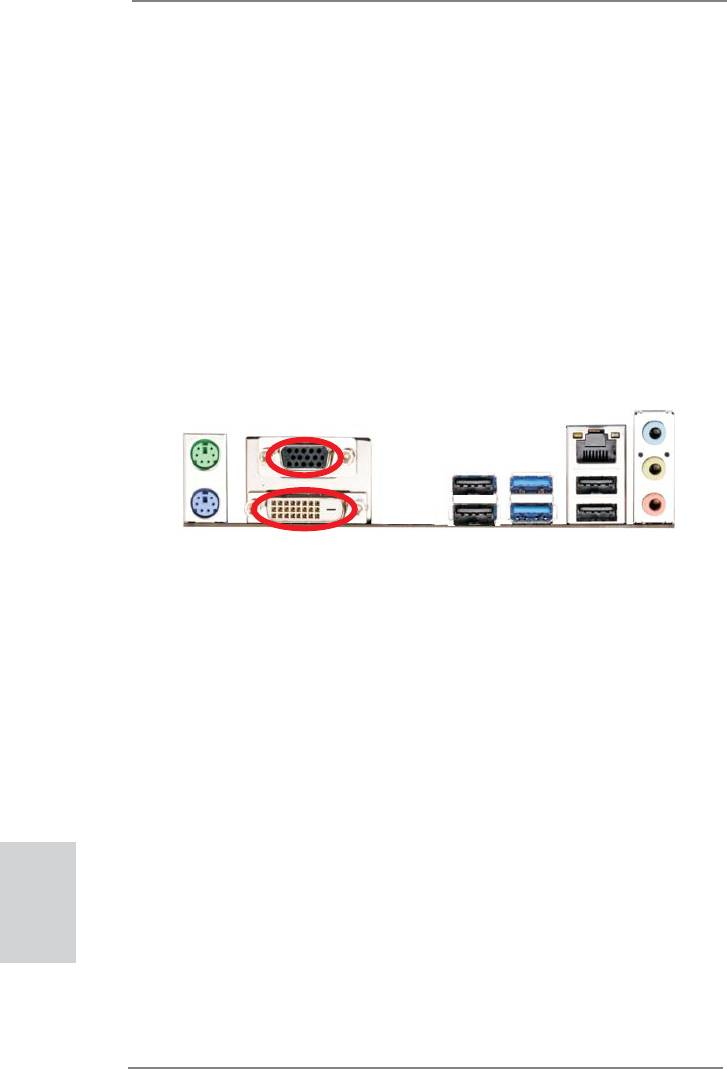
2.8 Dual Monitor and Surround Display Features
Dual Monitor Feature
This motherboard supports dual monitor feature. With the internal VGA output sup-
port (DVI-D and D-Sub), you can easily enjoy the benefi ts of dual monitor feature
without installing any add-on VGA card to this motherboard. This motherboard also
provides independent display controllers for DVI-D and D-Sub to support dual VGA
output so that DVI-D and D-sub can drive same or different display contents.
To enable dual monitor feature, please follow the below steps:
1. Connect DVI-D monitor cable to DVI-D port on the I/O panel, and connect D-Sub
monitor cable to D-Sub port on the I/O panel.
D-Sub port
DVI-D port
2. If you have installed onboard VGA driver from our support CD to your system
already, you can freely enjoy the benefi ts of dual monitor function after your
system boots. If you haven’t installed onboard VGA driver yet, please install
onboard VGA driver from our support CD to your system and restart your
computer.
English
22
ASRock B75M-GL R2.0 Motherboard

Surround Display Feature
This motherboard supports surround display upgrade. With the internal VGA output
support (DVI-D and D-Sub) and external add-on PCI Express VGA cards, you can
easily enjoy the benefi ts of surround display feature.
Please refer to the following steps to set up a surround display environment:
1. Install the PCI Express VGA card on PCIE1 and PCIE2 slots. Please refer to
page 17 for proper expansion card installation procedures for details.
2. Connect DVI-D monitor cable to DVI-D port on the I/O panel, and connect
D-Sub monitor cable to D-Sub port on the I/O panel. Then connect other
monitor cables to the corresponding connectors of the add-on PCI Express VGA
card on PCIE1 and PCIE2 slots.
3. Boot your system. Press <F2> or <Del> to enter UEFI setup. Enter “Onboard
VGA Share Memory” option to adjust the memory capability to [32MB], [64MB],
[128MB], [256MB] or [512MB] to enable the function of D-sub. Please make sure
that the value you select is less than the total capability of the system memory.
If you do not adjust the UEFI setup, the default value of “Onboard VGA Share
Memory”, [Auto], will disable D-Sub function when the add-on VGA card is
inserted to this motherboard.
4. Install the onboard VGA driver and the add-on PCI Express VGA card driver to
your system. If you have installed the drivers already, there is no need to install
them again.
5. Set up a multi-monitor display.
®
For Windows
XP / XP 64-bit OS:
Right click the desktop, choose “Properties”, and select the “Settings” tab
so that you can adjust the parameters of the multi-monitor according to
the steps below.
A. Click the “Identify” button to display a large number on each monitor.
B. Right-click the display icon in the Display Properties dialog that you
wish to be your primary monitor, and then select “Primary”. When
you use multiple monitors with your card, one monitor will always be
Primary, and all additional monitors will be designated as Secondary.
C. Select the display icon identifi ed by the number 2.
D. Click “Extend my Windows desktop onto this monitor”.
E. Right-click the display icon and select “Attached”, if necessary.
F. Set the “Screen Resolution” and “Color Quality” as appropriate for the
English
second monitor. Click “Apply” or “OK” to apply these new values.
G. Repeat steps C through E for the diaplay icon identifi ed by the
numbers three to six.
23
ASRock B75M-GL R2.0 Motherboard

®
TM
TM
For Windows
7 / 7 64-bit / Vista
/ Vista
64-bit OS:
Right click the desktop, choose “Personalize”, and select the “Display
Settings” tab so that you can adjust the parameters of the multi-monitor
according to the steps below.
A. Click the number ”2” icon.
B. Click the items “This is my main monitor” and “Extend the desktop onto
this monitor”.
C. Click “OK” to save your change.
D. Repeat steps A through C for the display icon identifi ed by the number
three to six.
6. Use Surround Display. Click and drag the display icons to positions representing
the physical setup of your monitors that you would like to use. The placement
of display icons determines how you move items from one monitor to another.
HDCP Function
HDCP function is supported on this motherboard. To use HDCP
function with this motherboard, you need to adopt the monitor
that supports HDCP function as well. Therefore, you can enjoy
the superior display quality with high-defi nition HDCP
encryption contents. Please refer to below instruction for more
details about HDCP function.
What is HDCP?
HDCP stands for High-Bandwidth Digital Content Protection,
®
a specifi cation developed by Intel
for protecting digital
entertainment content that uses the DVI interface. HDCP is a
copy protection scheme to eliminate the possibility of
intercepting digital data midstream between the video source,
or transmitter - such as a computer, DVD player or set-top box -
and the digital display, or receiver - such as a monitor, television
or projector. In other words, HDCP specifi cation is designed to
protect the integrity of content as it is being transmitted.
English
Products compatible with the HDCP scheme such as DVD
players, satellite and cable HDTV set-top-boxes, as well as few
entertainment PCs requires a secure connection to a compliant
display. Due to the increase in manufacturers employing HDCP
in their equipment, it is highly recommended that the HDTV or
LCD monitor you purchase is compatible.
24
ASRock B75M-GL R2.0 Motherboard
2.9 ASRock Smart Remote Installation Guide
ASRock Smart Remote is only used for ASRock motherboard with CIR header.
Please refer to below procedures for the quick installation and usage of ASRock
Smart Remote.
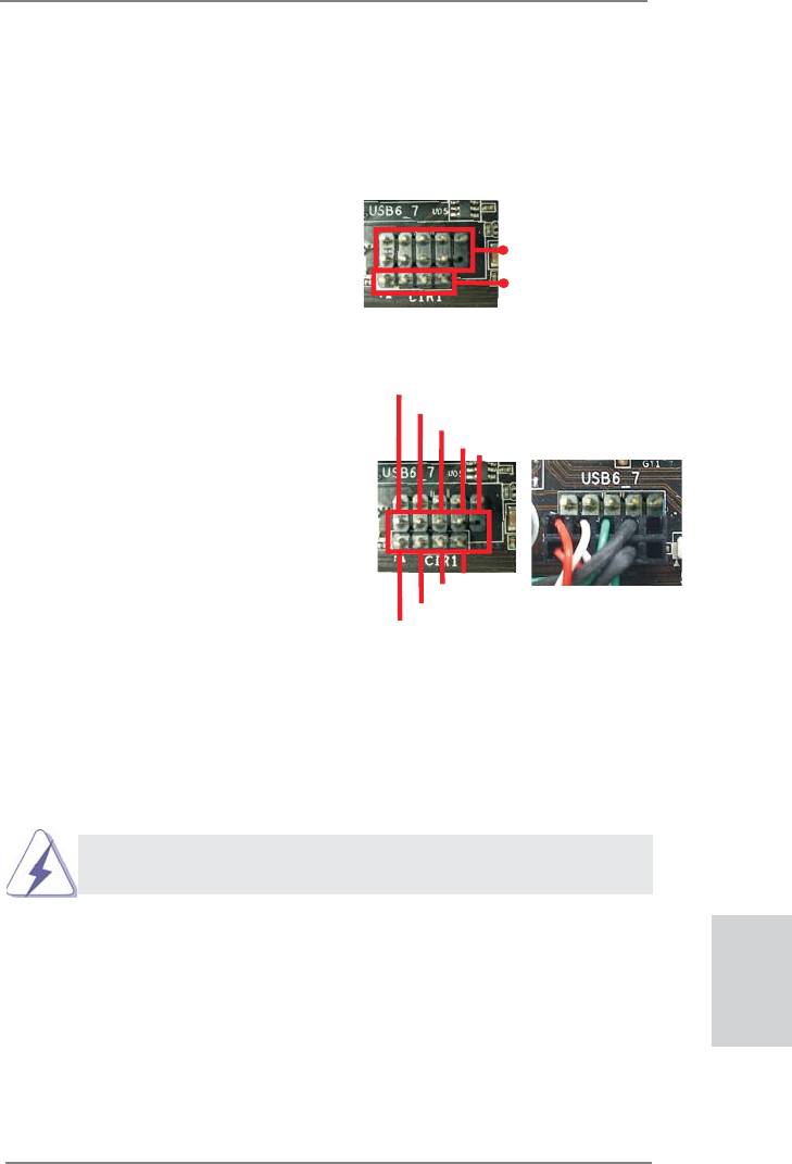
Step1. Find the CIR header located next
to the USB 2.0 header on ASRock
USB 2.0 header (9-pin, black)
motherboard.
CIR header (4-pin, gray)
Step2. Connect the front USB cable to the
USB_PWR
P-
USB 2.0 header (as below, pin 1-5)
P+
and the CIR header. Please make
GND
DUMMY
sure the wire assignments and the
pin assignments are matched
correctly.
1
2
3
4
5
GND
IRTX
IRRX
ATX+5VSB
Step3. Install Multi-Angle CIR Receiver to the front USB port.
Step4. Boot up your system. Press <F2> or <Del> to enter BIOS Setup Utility.
Make sure the option "CIR Controller" is setting at [Enabled].
(Advanced -> Super IO Confi guration -> CIR Controller -> [Enabled])
If you cannot fi nd this option, please shut down your system and install
Multi-Angle CIR Receiver to the other front USB port then try again.
Step5. Enter Windows. Execute ASRock support CD and install CIR Driver. (It is
listed at the bottom of driver list.)
English
25
ASRock B75M-GL R2.0 Motherboard
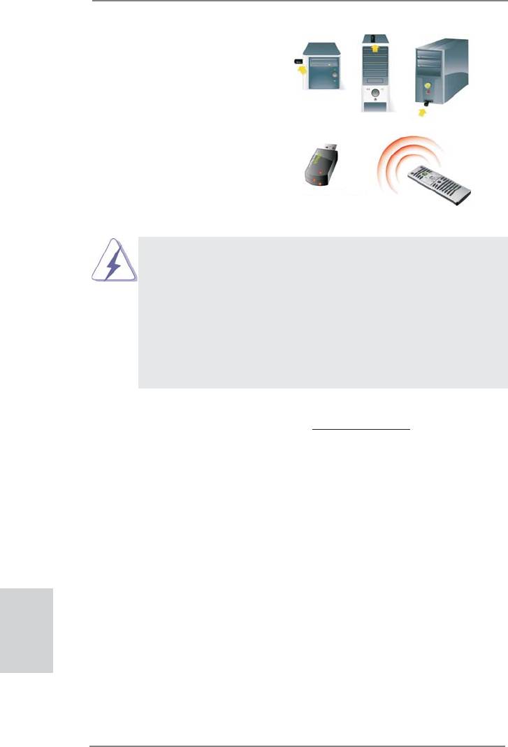
3 CIR sensors in different angles
1. Only one of the front USB port can support CIR function. When
the CIR function is enabled, the other port will remain USB
function.
2. Multi-Angle CIR Receiver
is used for front USB only. Please do
not use the rear USB bracket to connect it on the rear panel.
Multi-Angle CIR Receiver can receive the multi-direction infrared
signals (top, down and front), which is compatible with most of
the chassis on the market.
3. The Multi-Angle CIR Receiver does not support Hot-Plug
function. Please install it before you boot the system.
* ASRock Smart Remote is only supported by some of ASRock motherboards. Please refer to
ASRock website for the motherboard support list: http://www.asrock.com
English
26
ASRock B75M-GL R2.0 Motherboard
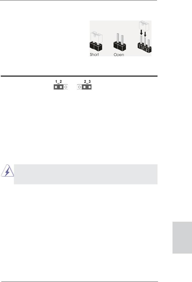
2.10 Jumpers Setup
The illustration shows how jumpers are
setup. When the jumper cap is placed on
pins, the jumper is “Short”. If no jumper cap
is placed on pins, the jumper is “Open”. The
illustration shows a 3-pin jumper whose
pin1 and pin2 are “Short” when jumper cap
is placed on these 2 pins.
Jumper Setting Description
Clear CMOS Jumper
(CLRCMOS1)
(see p.2, No. 31)
Clear CMOSDefault
Note: CLRCMOS1 allows you to clear the data in CMOS. To clear and reset the
system parameters to default setup, please turn off the computer and unplug
the power cord from the power supply. After waiting for 15 seconds, use a
jumper cap to short pin2 and pin3 on CLRCMOS1 for 5 seconds. However,
please do not clear the CMOS right after you update the BIOS. If you need
to clear the CMOS when you just fi nish updating the BIOS, you must boot
up the system fi rst, and then shut it down before you do the clear-CMOS ac-
tion. Please be noted that the password, date, time, user default profi le, 1394
GUID and MAC address will be cleared only if the CMOS battery is removed.
If you clear the CMOS, the case open may be detected. Please adjust
the BIOS option “Clear Status” to clear the record of previous chassis
intrusion status.
English
27
ASRock B75M-GL R2.0 Motherboard
2.11 Onboard Headers and Connectors
Onboard headers and connectors are NOT jumpers. Do NOT place
jumper caps over these headers and connectors. Placing jumper caps
over the headers and connectors will cause permanent damage of the
motherboard!
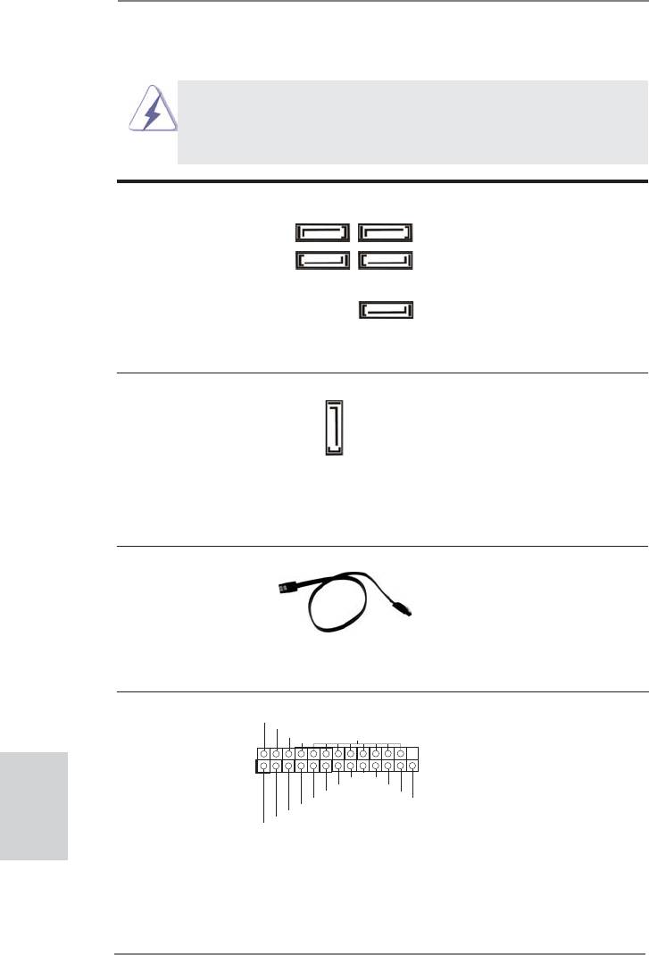
Serial ATA2 Connectors These fi ve Serial ATA2 (SATA2)
SATA2_1 SATA2_3
(SATA2_1: see p.2, No. 12)
connectors support SATA data
(SATA2_2: see p.2, No. 17)
cables for internal storage
(SATA2_3: see p.2, No. 13)
devices. The current SATA2
(SATA2_4: see p.2, No. 14)
interface allows up to 3.0 Gb/s
SATA2_2 SATA2_4
(SATA2_5: see p.2, No. 16)
data transfer rate.
SATA2_5
Serial ATA3 Connector This Serial ATA3 (SATA3)
(SATA3_0: see p.2, No. 7)
connector supports SATA data
cables for internal storage
SATA3_0
devices. The current SATA3
interface allows up to 6.0 Gb/s
data transfer rate.
Serial ATA (SATA) Either end of the SATA data
Data Cable cable can be connected to the
(Optional)
SATA / SATA2 / SATA3 hard
disk or the SATA2 / SATA3
connector on this motherboard.
Print Port Header This is an interface for print port
AFD#
(25-pin LPT1)
ERROR#
cable that allows convenient
PINIT#
SLIN#
GND
(see p.2, No. 24)
connection of printer devices.
English
1
SPD7
SPD6
ACK#
SPD5
BUSY
SPD4
PE
SPD3
SLCT
SPD2
SPD1
SPD0
STB#
28
ASRock B75M-GL R2.0 Motherboard
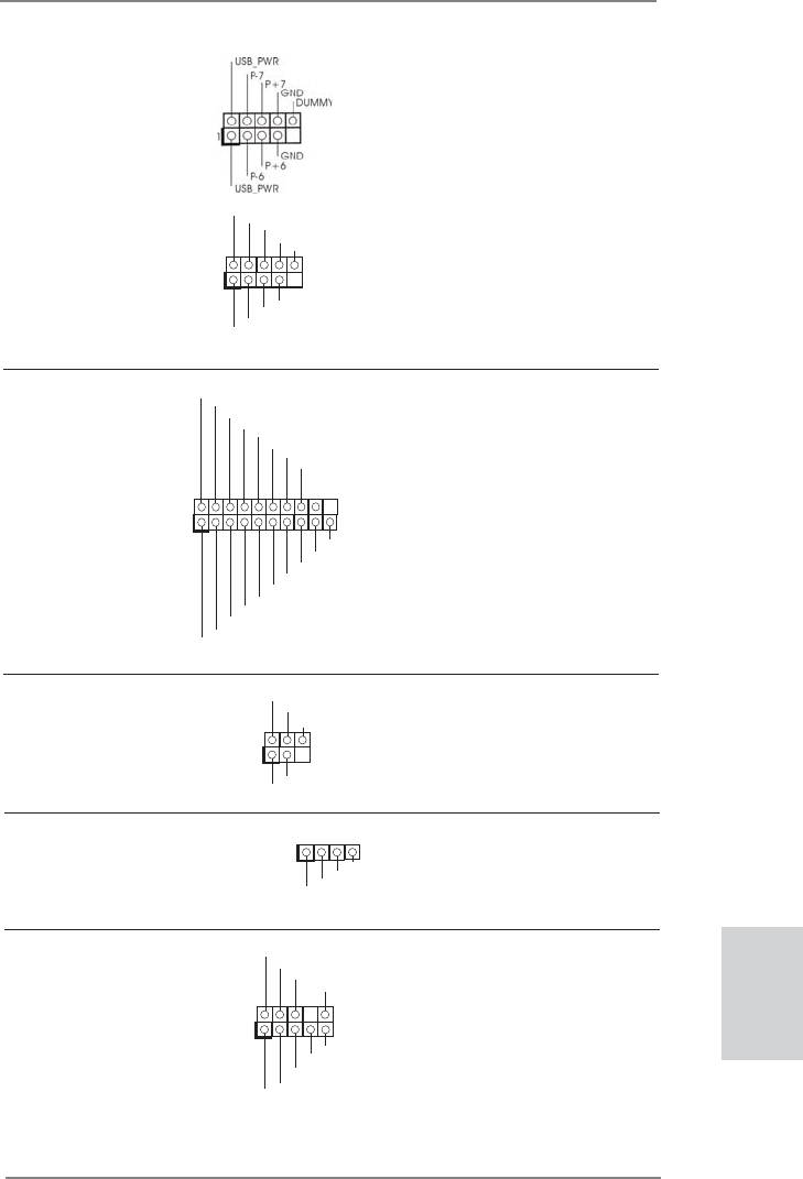
USB 2.0 Headers Besides four default USB 2.0
(9-pin USB6_7)
ports on the I/O panel, there are
(see p.2, No. 19)
two USB 2.0 headers on this
motherboard. Each USB 2.0
header can support two USB 2.0
ports.
USB_PWR
P-9
P+9
(9-pin USB8_9)
GND
DUMMY
(see p.2, No. 20)
1
GND
P+8
P-8
USB_PWR
USB 3.0 Header Besides two default USB 3.0
(19-pin USB3_2_3)
ports on the I/O panel, there is
(see p.2, No. 9)
one USB 3.0 header on this
motherboard. This USB 3.0
header can support two USB 3.0
ports.
1
Infrared Module Header This header supports an
(5-pin IR1)
optional wireless transmitting
(see p.2, No. 22)
and receiving infrared module.
Consumer Infrared Module Header This header can be used to
(4-pin CIR1)
connect the remote controller
(see p.2, No. 21)
receiver.
Front Panel Audio Header This is an interface for front
(9-pin HD_AUDIO1)
panel audio cable that allows
(see p.2, No. 30)
convenient connection and
control of audio devices.
English
29
ASRock B75M-GL R2.0 Motherboard
DUMMY
IntA_P0_D+
IntA_P0_D-
GND
IntA_P0_SSTX+
IntA_P0_SSTX-
GND
IntA_P0_SSRX+
IntA_P0_SSRX-
Vbus
Vbus
IntA_P1_SSRX-
IntA_P1_SSRX+
GND
IntA_P1_SSTX-
IntA_P1_SSTX+
GND
IntA_P1_D-
IntA_P1_D+
IRTX
+5VSB
DUMMY
1
GND
IRRX
1
GND
IRTX
IRRX
ATX+5VSB
GND
PRESENCE#
MIC_RET
OUT_RET
1
OUT2_L
J_SENSE
OUT2_R
MIC2_R
MIC2_L
1. High Defi nition Audio supports Jack Sensing, but the panel wire on the
chassis must support HDA to function correctly. Please follow the
instruction in our manual and chassis manual to install your system.
2. If you use AC’97 audio panel, please install it to the front panel audio
header as below:
A. Connect Mic_IN (MIC) to MIC2_L.
B. Connect Audio_R (RIN) to OUT2_R and Audio_L (LIN) to OUT2_L.
C. Connect Ground (GND) to Ground (GND).
D. MIC_RET and OUT_RET are for HD audio panel only. You don’t need
to connect them for AC’97 audio panel.
E. To activate the front mic.
®
For Windows
XP / XP 64-bit OS:
Select “Mixer”. Select “Recorder”. Then click “FrontMic”.
®
TM
TM
For Windows
7 / 7 64-bit / Vista
/ Vista
64-bit OS:
Go to the “FrontMic” Tab in the Realtek Control panel. Adjust
“Recording Volume”.
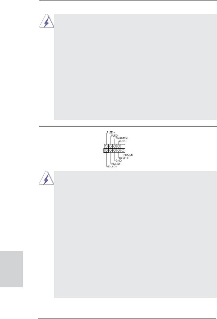
System Panel Header This header accommodates
(9-pin PANEL1)
several system front panel
(see p.2, No. 18)
functions.
Connect the power switch, reset switch and system status indicator on the
chassis to this header according to the pin assignments below. Note the
positive and negative pins before connecting the cables.
PWRBTN (Power Switch):
Connect to the power switch on the chassis front panel. You may confi gure
the way to turn off your system using the power switch.
RESET (Reset Switch):
Connect to the reset switch on the chassis front panel. Press the reset
switch to restart the computer if the computer freezes and fails to perform a
normal restart.
PLED (System Power LED):
Connect to the power status indicator on the chassis front panel. The LED
English
is on when the system is operating. The LED keeps blinking when the sys-
tem is in S1/S3 sleep state. The LED is off when the system is in S4 sleep
state or powered off (S5).
HDLED (Hard Drive Activity LED):
Connect to the hard drive activity LED on the chassis front panel. The LED
is on when the hard drive is reading or writing data.
30
ASRock B75M-GL R2.0 Motherboard
The front panel design may differ by chassis. A front panel module mainly
consists of power switch, reset switch, power LED, hard drive activity LED,
speaker and etc. When connecting your chassis front panel module to this
header, make sure the wire assignments and the pin assign-ments are
matched correctly.
Chassis Speaker Header Please connect the chassis
1
(4-pin SPEAKER 1)
speaker to this header.
SPEAKER
DUMMY
+5V
DUMMY
(see p.2, No. 15)
Chassis and Power Fan Connectors Please connect the fan cables
(4-pin CHA_FAN1)
to the fan connectors and match
GND
+12V
(see p.2, No. 8)
the black wire to the ground pin.
CHA_FAN_SPEED
FAN_SPEED_CONTROL
CHA_FAN1 supports Fan
(3-pin PWR_FAN1)
Control.
PWR_FAN_SPEED
(see p.2, No. 1)
+12V
GND
CPU Fan Connectors Please connect the CPU fan
FAN_SPEED_CONTROL
CPU_FAN_SPEED
(4-pin CPU_FAN1)
cable to the connector and
+12V
(see p.2, No. 4)
GND
match the black wire to the
ground pin.
1 2 3 4
Though this motherboard provides 4-Pin CPU fan (Quiet Fan) support, the 3-Pin
CPU fan still can work successfully even without the fan speed control function.
If you plan to connect the 3-Pin CPU fan to the CPU fan connector on this
motherboard, please connect it to Pin 1-3.
Pin 1-3 Connected
3-Pin Fan Installation
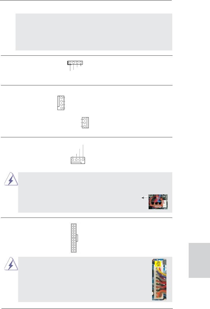
ATX Power Connector Please connect an ATX power
12
24
(24-pin ATXPWR1)
supply to this connector.
(see p.2, No. 6)
1
13
Though this motherboard provides 24-pin ATX power connector,
12
24
it can still work if you adopt a traditional 20-pin ATX power supply.
English
To use the 20-pin ATX power supply, please plug your
power supply along with Pin 1 and Pin 13.
20-Pin ATX Power Supply Installation
1
13
31
ASRock B75M-GL R2.0 Motherboard
ATX 12V Power Connector Please connect an ATX 12V
(4-pin ATX12V1)
power supply to this connector.
(see p.2, No. 2)
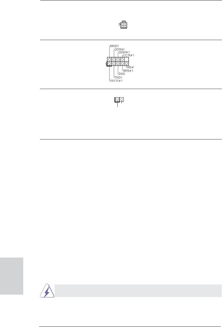
Serial port Header This COM1 header supports a
(9-pin COM1)
serial port module.
(see p.2, No. 23)
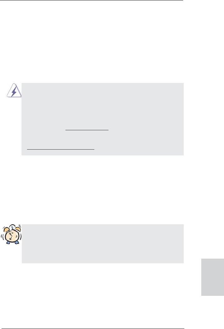
Chassis Intrusion Header This motherboard supports
(2-pin CI1)
1
CASE OPEN detection feature
GND
(see p.2, No. 25)
that detects if the chassis cover
Signal
has been removed. This feature
requires a chassis with chassis
intrusion detection design.
2.12 Driver Installation Guide
To install the drivers to your system, please insert the support CD to your optical
drive fi rst. Then, the drivers compatible to your system can be auto-detected and
listed on the support CD driver page. Please follow the order from top to bottom to
install those required drivers. Therefore, the drivers you install can work properly.
®
TM
TM
2.13 Installing Windows
7 / 7 64-bit / Vista
/ Vista
64-bit / XP /
XP 64-bit Without RAID Functions
®
TM
TM
If you want to install Windows
7 / 7 64-bit / Vista
/ Vista
64-bit / XP / XP 64-bit
OS on your SATA / SATA2 / SATA3 HDDs without RAID functions, please follow the
procedures below according to the OS you install.
®
2.13.1 Installing Windows
XP / XP 64-bit Without RAID Functions
English
®
If you want to install Windows
XP / XP 64-bit OS on your SATA / SATA2 / SATA3
HDDs without RAID functions, please follow the steps below.
®
AHCI mode is not supported under Windows
XP / XP 64-bit.
32
ASRock B75M-GL R2.0 Motherboard

Using SATA / SATA2 / SATA3 HDDs without NCQ function
STEP 1: Set Up UEFI.
A. Enter UEFI SETUP UTILITY Advanced screen Storage Confi guration.
B. Set the option “SATA Mode Selection” to [IDE].
®
STEP 2: Install Windows
XP / XP 64-bit OS on your system.
®
TM
TM
2.13.2 Installing Windows
7 / 7 64-bit / Vista
/ Vista
64-bit
Without RAID Functions
®
TM
TM
If you want to install Windows
7 / 7 64-bit / Vista
/ Vista
64-bit OS on your SATA
/ SATA2 / SATA3 HDDs without RAID functions, please follow the steps below.
Using SATA / SATA2 / SATA3 HDDs without NCQ function
STEP 1: Set Up UEFI.
A. Enter UEFI SETUP UTILITY Advanced screen Storage Confi guration.
B. Set the option “SATA Mode Selection” to [IDE].
®
TM
TM
STEP 2: Install Windows
7 / 7 64-bit / Vista
/ Vista
64-bit OS on your
system.
Using SATA / SATA2 / SATA3 HDDs with NCQ function
STEP 1: Set Up UEFI.
A. Enter UEFI SETUP UTILITY Advanced screen Storage Confi guration.
B. Set the option “SATA Mode Selection” to [AHCI].
®
TM
TM
STEP 2: Install Windows
7 / 7 64-bit / Vista
/ Vista
64-bit OS on your
system.
English
33
ASRock B75M-GL R2.0 Motherboard

3. BIOS Information
The Flash Memory on the motherboard stores BIOS Setup Utility. When you start up
the computer, please press <F2> or <Del> during the Power-On-Self-Test (POST)
to enter BIOS Setup utility; otherwise, POST continues with its test routines. If you
wish to enter BIOS Setup after POST, please restart the system by pressing <Ctl>
+ <Alt> + <Delete>, or pressing the reset button on the system chassis. The BIOS
Setup program is designed to be user-friendly. It is a menu-driven program, which
allows you to scroll through its various sub-menus and to select among the prede-
termined choices. For the detailed information about BIOS Setup, please refer to the
User Manual (PDF fi le) contained in the Support CD.
4. Software Support CD information
®
®
This motherboard supports various Microsoft
Windows
operating systems: 7 / 7
TM
TM
64-bit / Vista
/ Vista
64-bit / XP / XP 64-bit. The Support CD that came with the
motherboard contains necessary drivers and useful utilities that will enhance moth-
erboard features. To begin using the Support CD, insert the CD into your CD-ROM
drive. It will display the Main Menu automatically if “AUTORUN” is enabled in your
computer. If the Main Menu does not appear automatically, locate and double-click
on the fi le “ASSETUP.EXE” from the BIN folder in the Support CD to display the
menus.
English
34
ASRock B75M-GL R2.0 Motherboard
1. Einführung
Wir danken Ihnen für den Kauf des ASRock B75M-GL R2.0 Motherboard, ein zu-
verlässiges Produkt, welches unter den ständigen, strengen Qualitätskontrollen von
ASRock gefertigt wurde. Es bietet Ihnen exzellente Leistung und robustes Design,
gemäß der Verpflichtung von ASRock zu Qualität und Halbarkeit. Diese Schnel-
linstallationsanleitung führt in das Motherboard und die schrittweise Installation
ein. Details über das Motherboard fi nden Sie in der Bedienungsanleitung auf der
Support-CD.
Da sich Motherboard-Spezifi kationen und BIOS-Software verändern können,
kann der Inhalt dieses Handbuches ebenfalls jederzeit geändert werden. Für
den Fall, dass sich Änderungen an diesem Handbuch ergeben, wird eine neue
Version auf der ASRock-Website, ohne weitere Ankündigung, verfügbar sein.
Die neuesten Grafi kkarten und unterstützten CPUs sind auch auf der ASRock-
Website aufgelistet.
ASRock-Website: http://www.asrock.com
Wenn Sie technische Unterstützung zu Ihrem Motherboard oder spezifi sche
Informationen zu Ihrem Modell benötigen, besuchen Sie bitte unsere Webseite:
www.asrock.com/support/index.asp
1.1 Kartoninhalt
ASRock B75M-GL R2.0 Motherboard
(Micro ATX-Formfaktor: 24.4 cm x 21.3 cm; 9.6 Zoll x 8.4 Zoll)
ASRock B75M-GL R2.0 Schnellinstallationsanleitung
ASRock B75M-GL R2.0 Support-CD
Zwei Serial ATA (SATA) -Datenkabel (optional)
Ein I/O Shield
ASRock erinnert...
®
TM
TM
Zur besseren Leistung unter Windows
7 / 7, 64 Bit / Vista
/ Vista
64 Bit empfehlen wir, die Speicherkonfi guration im BIOS auf den AHCI-
Modus einzustellen. Hinweise zu den BIOS-Einstellungen fi nden Sie in
der Bedienungsanleitung auf der mitgelieferten CD.
Deutsch
35
ASRock B75M-GL R2.0 Motherboard

1.2 Spezifikationen
Plattform - Micro ATX-Formfaktor: 24.4 cm x 21.3 cm; 9.6 Zoll x 8.4 Zoll
- Alle Feste Kondensatordesign
®
TM
CPU - Unterstützt Intel
Core
i7- / i5- / i3-Prozessoren der 3ten
und 2ten Generation im LGA1155-Package
®
- Unterstützt Intel
Turbo Boost 2.0-Technologie
- Unterstützt Hyper-Threading-Technologie
(siehe VORSICHT 1)
®
Chipsatz - Intel
B75
®
- Unterstützt Intel
Small Business Advantage
(siehe VORSICHT 2)
®
- Unterstützt Intel
Rapid Start Technology und Smart
Connect Technology
Speicher - Dual-Kanal DDR3 Speichertechnologie (siehe VORSICHT 3)
- 2 x Steckplätze für DDR3
- Unterstützt DDR3 1600/1333/1066 non-ECC, ungepufferter
®
Speicher (DDR3 1600 mit Intel
Ivy Bridge-Prozessor,
®
DDR3 1333 mit Intel
Sandy Bridge-Prozessor)
- Max. Kapazität des Systemspeichers: 16GB
(siehe VORSICHT 4)
®
- Unterstützt Intel
Extreme Memory Profi le (XMP)1.3/1.2
Erweiterungs- - 1 x PCI Express 3.0 x16-Steckplätze (PCIE1: x16-Modus)
steckplätze (siehe VORSICHT 5)
®
* PCIE 3.0 wird nur mit Intel
Ivy Bridge-Prozessor
®
unterstützt. Mit Intel
Sandy Bridge-Prozessor wird nur
PCIE 2.0 unterstützt.
- 1 x PCI Express 2.0 x16-Steckplätze (PCIE2: x4-Modus)
- 2 x PCI-Steckplätze
TM
TM
TM
- Unterstützt AMD
Quad CrossFireX
und CrossFireX
®
Onboard-VGA * Integrierte Intel
HD-Grafi kdarstellungen und die VGA-
Ausgänge können nur durch GPU-integrierte Prozessoren
unterstützt werden.
Deutsch
®
- Unterstützt hochaufl ösende integrierte Intel
-Grafi klösungen:
®
®
TM
®
Intel
Quick-Sync-Video 2.0, Intel
InTru
3D, Intel
Clear-
®
TM
®
Video-Technik (HD), Intel
Insider
, Intel
HD Graphics
2500/4000
®
- Pixel Shader 5.0, DirectX 11 mit Intel
Ivy Bridge-Prozessor,
®
Pixel Shader 4.1, DirectX 10.1 mit Intel
Sandy Bridge-
Prozessor
36
ASRock B75M-GL R2.0 Motherboard

- Maximal gemeinsam genutzter Speicher 1760MB
(siehe VORSICHT 6)
- Doppel-VGA Ausgabe: unterstützt DVI und D-Sub Ports
durch unabhängige Bildschirmanzeige Kontrolleure
- Unterstützt DVI mit einer maximalen Aufl ösung von 1920 x
1200 bei 60 Hz
- Unterstützt D-Sub mit einer maximalen Aufl ösung von 2048
x 1536 bei 75 Hz
- Unterstützt HDCP-Funktion mit DVI-Port
- Unterstutzt 1080p Blu-ray (BD) / HD-DVD-Wiedergabe mit
DVI-Port
Audio - 5.1
CH HD Audio (Realtek ALC662 Audio Codec)
LAN - PCIE x1 Gigabit LAN 10/100/1000 Mb/s
- Realtek RTL8111E
- Unterstützt Wake-On-LAN
- Unterstützt LAN-Kabelerkennung
- Unterstützt energieeffi zientes Ethernet 802.3az
- Unterstützt PXE
E/A-Anschlüsse I/O Panel
an der Rückseite - 1 x PS/2-Mausanschluss
- 1 x PS/2-Tastaturanschluss
- 1 x D-Sub port
- 1 x DVI-D port
- 4 x Standard-USB 2.0-Anschlüsse
- 2 x Standard-USB 3.0-Anschlüsse
- 1 x RJ-45 LAN Port mit LED (ACT/LINK LED und SPEED
LED)
- HD Audiobuchse: Audioeingang / Lautsprecher vorne /
Mikrofon
SATA3 - 1 x SATA 3-Anschlüsse (6,0 Gb/s); unterstützt NCQ-, AHCI-
und Hot Plug Funktionen
USB3.0 - 2 x USB 3.0-Ports an der Rückseite, unterstützt USB
1.0/2.0/3.0 mit bis zu 5 Gb/s
- 1 x USB 3.0-Header (unterstützt zwei USB 3.0-Ports) an der
Vorderseite, unterstützt USB 1.0/2.0/3.0 mit bis zu 5 Gb/s
Anschlüsse - 5 x SATA2 3,0 GB/s-Anschlüsse, unterstützen NCQ-, AHCI-
und Hot Plug Funktionen
Deutsch
- 1 x SATA3 6,0 GB/s-Anschlüsse
- 1 x Infrarot-Modul-Header
- 1 x
Consumer Infrared-Modul-Header
- 1 x Druckerport-Anschlussleiste
37
ASRock B75M-GL R2.0 Motherboard

- 1 x COM-Anschluss-Header
- 1 x Verteiler für Gehäuseeindringversuche
- 1 x CPUlüfter-Anschluss (4-pin)
- 1 x Gehäuselüfter-Anschluss (4-pin)
- 1 x Stromlüfter-Anschluss (3-pin)
- 24-pin ATX-Netz-Header
- 4-pin anschluss für 12V-ATX-Netzteil
- Anschluss für Audio auf der Gehäusevorderseite
- 2 x USB 2.0-Anschlüsse (Unterstützung 4 zusätzlicher
USB 2.0-Anschlüsse)
- 1 x USB 3.0-Anschlüsse (Unterstützung 2 zusätzlicher
USB 3.0-Anschlüsse)
BIOS - 64Mb AMIs Legal BIOS UEFI mit GUI-Unterstützung
- Unterstützung für “Plug and Play”
- ACPI 1.1-Weckfunktionen
- JumperFree-Modus
- SMBIOS 2.3.1
- CPU Core, IGPU, DRAM, 1.8V PLL, VTT, VCCSA
Stromspannung Multianpassung
CD d’assistance - Treiber, Dienstprogramme, Antivirussoftware (Probeversion),
CyberLink MediaEspresso 6.5-Testversion, ASRock
MAGIX-Multimedia-Suite - OEM
Einzigartige - ASRock Extreme Tuning Utility (AXTU)
Eigenschaft (siehe VORSICHT 7)
- ASRock Sofortstart
- ASRock Instant Flash (siehe VORSICHT 8)
- ASRock APP Charger (siehe VORSICHT 9)
- ASRock SmartView (siehe VORSICHT 10)
- ASRock XFast USB (siehe VORSICHT 11)
- ASRock XFast LAN (siehe VORSICHT 12)
- ASRock XFast RAM (siehe VORSICHT 13)
- ASRock Crashless BIOS (siehe VORSICHT 14)
- ASRock OMG (Online Management Guard)
(siehe VORSICHT 15)
Deutsch
- ASRock Internet Flash (siehe VORSICHT 16)
- ASRock UEFI System Browser
- ASRock-Entfeuchterfunktion (siehe VORSICHT 17)
- Hybrid Booster:
- ASRock U-COP (siehe VORSICHT 18)
- Boot Failure Guard (B.F.G. – Systemstartfehlerschutz)
- Combo-Kühleroption (siehe VORSICHT 19)
- Gute Nacht-LED
38
ASRock B75M-GL R2.0 Motherboard
Hardware Monitor - Überwachung der CPU-Temperatur
- Motherboardtemperaturerkennung
- Drehzahlmessung für CPU/Gehäuse/Strom lüfter
- Geräuscharmer CPU-/Gehäuselüfter (ermöglicht die au
tomatische Anpassung der Gehäuselüftergeschwindigkeit
durch CPU-Temperatur)
- Mehrstufi ge Geschwindigkeitssteuerung für CPU/Gehäuse
lüfter
- GEHÄUSE OFFEN-Erkennung
- Spannungsüberwachung: +12V, +5V, +3.3V, Vcore
®
®
TM
Betriebssysteme - Unterstützt Microsoft
Windows
7 / 7 64-Bit / Vista
/
TM
Vista
64-Bit / XP / XP 64-Bit (siehe VORSICHT 20)
Zertifi zierungen - FCC, CE, WHQL
- Gemäß Ökodesign-Richtlinie (ErP/EuP) (Stromversorgung
gemäß Ökodesign-Richtlinie (ErP/EuP) erforderlich)
(siehe VORSICHT 21)
* Für die ausführliche Produktinformation, besuchen Sie bitte unsere Website:
http://www.asrock.com
WARNUNG
Beachten Sie bitte, dass Overclocking, einschließlich der Einstellung im BIOS,
Anwenden der Untied Overclocking-Technologie oder Verwenden von Overclocking-
Werkzeugen von Dritten, mit einem gewissen Risiko behaftet ist. Overclocking kann
sich nachteilig auf die Stabilität Ihres Systems auswirken oder sogar Komponenten
und Geräte Ihres Systems beschädigen. Es geschieht dann auf eigene Gefahr und
auf Ihre Kosten. Wir übernehmen keine Verantwortung für mögliche Schäden, die
aufgrund von Overclocking verursacht wurden.
VORSICHT!
1. Die Einstellung der “Hyper-Threading Technology”, fi nden Sie auf Seite
50 des auf der Support-CD enthaltenen Benutzerhandbuches beschrie-
ben.
®
2. Intel
Small Business Advantage ist eine in die IT-Werkzeuge integrierte,
anpassbare Plattform, die maximale Produktivität, PC-Leistung und
Datensicherheit unterstützt. Hier stehen Ihnen Anwendungen wie Soft-
ware Monitor, PC Health Center, Data Backup & Restore, Energy Saver
und USB Blocker.
Deutsch
3. Dieses Motherboard unterstützt Dual-Kanal-Speichertechnologie. Vor
Implementierung der Dual-Kanal-Speichertechnologie müssen Sie die In-
stallationsanleitung für die Speichermodule auf Seite 16 zwecks richtiger
Installation gelesen haben.
39
ASRock B75M-GL R2.0 Motherboard

4. Durch Betriebssystem-Einschränkungen kann die tatsächliche Speicher-
®
größe weniger als 4 GB betragen, da unter Windows
7 / Vista™ / XP
etwas Speicher zur Nutzung durch das System reserviert wird. Unter
®
Windows
OS mit 64-Bit-CPU besteht diese Einschränkung nicht. Sie
®
können ASRock XFast RAM zur Nutzung des Speichers, den Windows
nicht verwenden kann, einsetzen.
5. Unterstützt nur der PCIE1-Steckplatz Geschwindigkeiten der 3ten Gene-
ration. Damit Sie PCI Express mit der Geschwindigkeit der 3ten Genera-
tion nutzen können, müssen Sie einen Ivy Bridge-Prozessor installieren.
Wenn Sie einen Sandy Bridge-Prozessor installieren, läuft PCI Express
nur bei der Geschwindigkeit der 2ten Generation.
6. Die Maximalspeichergröße ist von den Chipshändler defi niert und umge-
®
tauscht. Bitte überprüfen Sie Intel
website für die neuliche Information.
7. ASRock Extreme Tuning Utility (AXTU) ist ein Alles-in-einem-
Werkzeug zur Feineinstellung verschiedener Systemfunktionen an
einer benutzerfreundlichen Schnittstelle; diese beinhaltet Hardware-
Überwachung, Lüftersteuerung, Übertaktung, OC DNA und IES. Über die
Hardware-Überwachung können Sie die Hauptsystemdaten einsehen.
Die Lüftersteuerung zeigt Ihnen zur Anpassung Lüftergeschwindigkeit
und Temperatur an. Bei der Übertaktung können Sie die CPU-Frequenz
zur Erzielung optimaler Systemleistung übertakten. OC DNA ermöglicht
Ihnen die Speicherung Ihrer OC-Einstellungen als Profi l, welches Sie
mit Freunden teilen können. Ihre Freunde können das OC-Profi l dann
in ihrem System laden und so die gleichen OC-Einstellungen erzielen.
Per IES (Intelligent Energy Saver) kann der Spannungsregulator bei
Inaktivität der CPU-Kerne die Anzahl an Ausgangsphasen zur Steigerung
der Effi zienz reduzieren – ohne die Rechenleistung zu beeinträchtigen.
Hinweise zur Bedienung der ASRock Extreme Tuning Utility (AXTU)
fi nden Sie auf unserer Webseite.
ASRock-Webseite: http://www.asrock.com
8. ASRock Instant Flash ist ein im Flash-ROM eingebettetes BIOS-Flash-
Programm. Mithilfe dieses praktischen BIOS-Aktualisierungswerkzeugs
können Sie das System-BIOS aktualisieren, ohne dafür zuerst Betriebs-
®
systeme wie MS-DOS oder Windows
aufrufen zu müssen. Mit diesem
Programm bekommen Sie durch Drücken der <F6>-Taste während des
POST-Vorgangs oder durch Drücken der <F2>-Taste im BIOS-Setup-
Menü Zugang zu ASRock Instant Flash. Sie brauchen dieses Werkzeug
einfach nur zu starten und die neue BIOS-Datei auf Ihrem USB-Flash-
Deutsch
Laufwerk, Diskettenlaufwerk oder der Festplatte zu speichern, und schon
können Sie Ihr BIOS mit nur wenigen Klickvorgängen ohne Bereitstellung
einer zusätzlichen Diskette oder eines anderen komplizierten Flash-Pro-
gramms aktualisieren. Achten Sie darauf, dass das USB-Flash-Laufwerk
oder die Festplatte das Dateisystem FAT32/16/12 benutzen muss.
9. Wenn Sie nach einer schnelleren, weniger eingeschränkten Möglichkeit
zur Aufl adung Ihrer Apple-Geräte (z. B. iPhone/iPad/iPod touch) suchen,
bietet ASRock Ihnen eine wunderbare Lösung – den ASRock
40
ASRock B75M-GL R2.0 Motherboard


