Kenwood DPX504U: Connecting Wires to Installation/Removing the Unit Terminals
Connecting Wires to Installation/Removing the Unit Terminals: Kenwood DPX504U
Connecting Wires to
Installation/Removing the Unit
Terminals
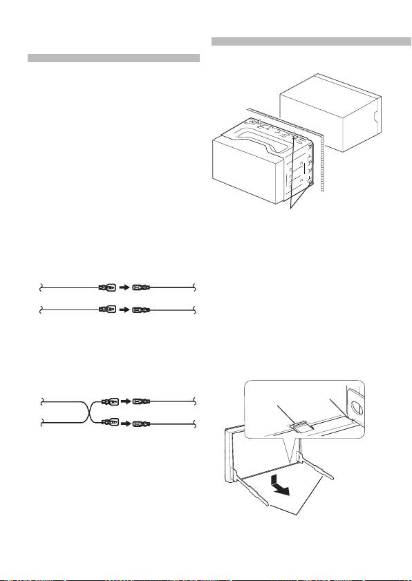
Installation
Connecting the ISO Connector
The pin arrangement for the ISO connectors
depends on the type of vehicle you drive.
Make sure to make the proper connections
to prevent damage to the unit.
The default connection for the wiring
harness is described in 1 below. If the ISO
connector pins are set as described in 2,
make the connection as illustrated.
Please be sure to reconnect the cable as
shown 2 below to install this unit to the
Volkswagen vehicles etc.
Bend the tabs of the mounting sleeve
with a screwdriver or similar utensil
1 (Default setting) The A-7 pin (red) of the
and attach it in place.
vehicle’s ISO connector is linked with
the ignition, and the A-4 pin (yellow) is
⁄
connected to the constant power supply.
• Make sure that the unit is installed
Ignition cable
A-7 Pin
securely in place. If the unit is unstable, it
(Red)
(Red)
may malfunction (for example, the sound
Unit
Vehicle
may skip).
Battery cable
A-4 Pin
Removing the hard rubber frame
(Yellow)
(Yellow)
Engage the catch pins on the removal
tool 2 and remove the two locks on the
2 The A-7 pin (red) of the vehicle’s ISO
lower level.
connector is connected to the constant
Lower the frame and pull it forward as
power supply, and the A-4 pin (yellow) is
shown in the figure.
linked to the ignition.
Ignition cable
A-7 Pin
(Red)
(Red)
Catch
Lock
Unit
Vehicle
Battery cable
A-4 Pin
(Yellow)
(Yellow)
Removal tool (Accessory
2)
12
|
Quick Start Guide
B59-2055-00_00_2DIN_E_QSG.indb 12 11/01/19 15:00
Table of contents
- Contents Before use
- Before use
- First step
- Basic Operations
- Playing Music (CD/USB/iPod)
- Listening to the Radio
- Appendix Installation accessories
- Before installation
- Connecting Wires to Terminals ⁄
- Connecting Wires to Terminals
- Connecting Wires to Installation/Removing the Unit Terminals
- Installation/Removing the Unit
- Table des matières Avant utilisation
- Avant utilisation
- Étape 1
- Fonctionnement basique
- Reproduire de la musique (CD/USB/iPod)
- Écoute de la radio
- Annexe Accessoires pour l'installation
- Avant installation
- Connexion des câbles aux bornes ⁄
- Connexion des câbles aux bornes
- Connexion des câbles Installation/Retrait de l’appareil aux bornes
- Installation/Retrait de l’appareil
- Inhalt Vor der Verwendung
- Vor der Verwendung
- Erste Schritte
- Grundbedienung
- Musikwiedergabe (CD/USB/iPod)
- Radiowiedergabe
- Anhang Montagezubehör
- Vor dem Einbau
- Anschlussdiagramm ⁄
- Anschlussdiagramm
- Anschlussdiagramm Einbau/Entfernen des Geräts
- Einbau/Entfernen des Geräts
- Inhoud Voor de ingebruikneming
- Voor de ingebruikneming
- Eerste stap
- Basisbediening
- Muziek afspelen (CD/USB/iPod)
- Naar de radio luisteren
- Appendix Installatieaccessoires
- Voor de installatie
- Verbinden van kabels met aansluitingen ⁄
- Verbinden van kabels met aansluitingen
- Verbinden van kabels Toestel installeren/ verwijderen met aansluitingen
- Toestel installeren/ verwijderen
- Sommario Prima dell'uso
- Prima dell'uso
- Primo passo
- Funzioni di base
- Riproduzione della musica (CD/USB/iPod)
- Ascolto della radio
- Appendice Accessori di installazione
- Prima dell'installazione
- Collegamento dei cavi ai terminali ⁄
- Collegamento dei cavi ai terminali
- Collegamento dei cavi Installazione/rimozione dell’unità ai terminali
- Installazione/rimozione dell’unità
- Índice Antes de usar
- Antes de usar
- Primer paso
- Funciones básicas
- Reproducción de música (CD/USB/iPod)
- Escuchar la radio
- Apéndice Instalación de accesorios
- Antes de la instalación
- Conexión de cables a los terminales ⁄
- Conexión de cables a los terminales
- Conexión de cables a Instalación/Desmontaje de la unidad los terminales
- Instalación/Desmontaje de la unidad
- Índice Antes da utilização
- Antes da utilização
- Primeiro passo
- Operação Básica
- Reproduzir música (CD/USB/iPod)
- Ouvir rádio
- Anexo Acessórios de instalação
- Antes da instalação
- Ligar os cabos aos terminais ⁄
- Ligar os cabos aos terminais
- Ligar os cabos aos Instalação/Retirar o aparelho terminais
- Instalação/Retirar o aparelho
- Содержание Подготовка к эксплуатации
- Подготовка к эксплуатации
- Первый шаг
- Основные операции
- Воспроизведение музыки (CD/USB/iPod)
- Прослушивание радио
- Приложение Принадлежности, используемые при
- Перед установкой
- Подсоединение кабелей к гнездам для подключения ⁄
- Подсоединение кабелей к гнездам для подключения
- Подсоединение Установка/Cнятие устройства кабелей к гнездам
- Установка/Cнятие устройства
- Зміст Перед використанням
- Перед використанням
- Перший крок
- Основні операції
- Відтворення музики (CD/USB/iPod)
- Прослуховування радіо
- Додаток Додаткове приладдя, необхідне для
- Перед встановленням
- Підключення кабелів до роз'ємів ⁄
- Підключення кабелів до роз'ємів
- Підключення кабелів Установка/виймання приладу до роз'ємів
- Установка/виймання приладу


