Alexika LR 1000 control Package: 25.0
25.0: Alexika LR 1000 control Package
26
Check whether the voltage specified on the type plate
(LR 1000 control base) matches the mains voltage available.
The power socket used must be
earthed (protective earth conductor
contact).
If these conditions are met, the device is ready to operate
after plugging in the mains plug.
If these procedures are not followed, safe operation cannot
be guaranteed and/or the equipment may be damaged.
Observe the ambient conditions (temperature, humidity,
etc.) listed under “
Technical Data
”.
The device is switched on using the switch in the front of
the equipment. Once it has been switched on, the device
name and software version appear in the display.
Commissioning
After a few seconds, the working screen is shown on the
screen, device is ready for operation.
Lab Reactor
LR 1000 Control
Version X.X.XXX/X.XX
Fig. 11
A
25.0
actual °C
0
10
set °C
set rpm
Safe Temp.: 210 °C
0
actual rpm
Fig. 12
Press rotating/pressing knob (
A
, see
Fig. 10
), the stirrer
start to running. Turn the rotating/pressing knob (
A
), the
target speed setting can be adjusted on the working screen.
Press rotating/pressing knob (
B
, see
Fig. 10
)to activate the
heating function. Turn the rotating/pressing knob (
B
), the
temperature setpoint can be adjusted.
Explanation of symbols on the working screen:
The symbols displayed change depending on the status and
settings of the instrument. The screen below shows the
most significant symbols on the working screen.
Key:
This symbol means that the function of the buttons and the
rotary knob (
G
, see
Fig. 10
) for controlling the device are
disabled.
The symbol no longer appears if the functions are enabled
once again by pressing the key button a second time.
Temperature Sensor Symbol:
This symbol indicates that the external temperature sensor
is inserted.
A
Operating Mode:
This symbol indicates the operating mode currently selected (A,
B, C).
USB:
This symbol means the device is communicating via a USB cable.
Heating
This symbol indicated the heating function is activated.
indicated active heating process.
Rotation:
This symbol indicates the rotation status of the stirrer.
PC
PC control:
This symbol indicates the device is control via a PC.
PC
A
Safe Temp.: 200 °C Timer: 00:00:00
pH-Value: 0.0
Δ
Torque: 0%
100.0
actual
°C
100
actual
rpm
100.0
set
°C
100
set
rpm
Fig. 12
Fig. 13
27
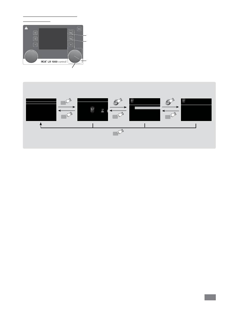
Menu navigation and structure:
Menu navigation
Press the “
Menu
” button (
C
).
Select the menu by turning the rotating/pressing knob (
A
) to the right or
left to select the desired menu or sub-menu, which can then be selectd by
pressing the rotating/pressing knob (
A
).
Push or turn the rotating/pressing knob (
A
) again to select the desired menu
option and edit the values or settings, or activate/deactivate a function.
Turn the rotating/pressing knob (
A
) on “
OK
“ or press the "
Back
" button
(
D
) or "
Menu
" button (
C
) to end the procedure and return to previous
menu or working screen.
Note:
The display shows the activated menu option highlighted in yellow color.
Stirring
Torque trend measurement
Intermittent mode
Speed limit
> Stirring
Torque trend measurement
The torque trend measurement
calculates the relative torque
changing inside the medium.
Note:
If you press the “
Menu
“ button (
C
), the system skips directly back to the working screen.
If you press the “
Back
“ button (
D
), the system skips back to the previous display.
Menu navigation:
Press the “
Menu
“ button (
C
) and rotate rotating/pressing knob (
A
)
Press the ”
Back
” button (
D
) or the ”
Menu
” button (
C
)
Stirring
Menu
A
25.0
actual °C
0
10
set °C
set rpm
Safe Temp. 210 °C
0
actual rpm
Menu
Menu
Back
Back
Back
Fig. 15
Navigation controls
in the menu
A
C
D
Fig. 14

28
Menu structure
Stirring
Torque trend measurement ……………………………………………………… -
Intermittent Mode
Run/Stop …………………………………........ -
Interval
Run Time…..…………... 01:00 [mm:ss]
Stop Time………………. 00:10 [mm:ss]
Speed limit ………………………………………………………………………... 150 rpm
Heating
Control method
Accurate ………………………………………… activated
Fast ……………………………………………… -
Limits
Medium limit …………………………………… 120
Limit information
Medium limit …………… 120
Heating block …………… 200
Temperature sensor
Calibration
2-point calibration ……… -
3-point calibration ……… -
Reset calibration values ………………………… -
Timer
Set………………………………………………………………………………….. 00:00:00 [hh:mm:ss]
Display…………………………………………………………………………….. -
Operating Mode
A………………………………………………………………….........………….. activated
B…………………………………………………………………….........……….. -
C…………………………………………………………………….........……….. -
Display
Torque trend measurement……………………………………………………... -
pH value……………………………………………………………………...…… -
Timer …………………………………………………………………..………….. -
Safety
Time Out
Set ……………………………………………… 00:30 [mm:ss]
Speed …………………………………………… 10 rpm
Temperature …………………………………… 30
º
C
Password …………………………..…………………………………................ 000
Safe Temp. confirmation …….………………………………………………… -
Factory settings
Menu
Weighing
pH Probe
Measurement …………………………………………………………………….. -
Calibration
2-point calibration ……………………………… -
3-point calibration ……………………………… -
Reset calibration values …………………………………………………………… -
Calibration
2-point calibration ……………………………… -
3-point calibration ……………………………… -
Reset pH probe ……………………………………………………………………. -
Display ……………………………………………………………………………… -
Settings
Languages
Display
Sound
Factory Settings
Bluetooth
Information
Version ………………………………………… yes
Operating Mode ……………………………… yes
Interval Run ………………………….………… yes
Interval Stop ………………………...………… yes
Medium Limit ………………………………… yes
Heating Block Limit …………………………… yes
Time Out ……………………………………… yes
Time Out Temperature ……………………… yes
Time Out Speed …………………………… yes
English…………………………………………. activated
Deutsch………………………………………… -
···
………………………………..……………………………………..… -
Background Black
………...……….... activated
White
………………….. -
Key Tone ……………………………………….. -
Fig. 16
29
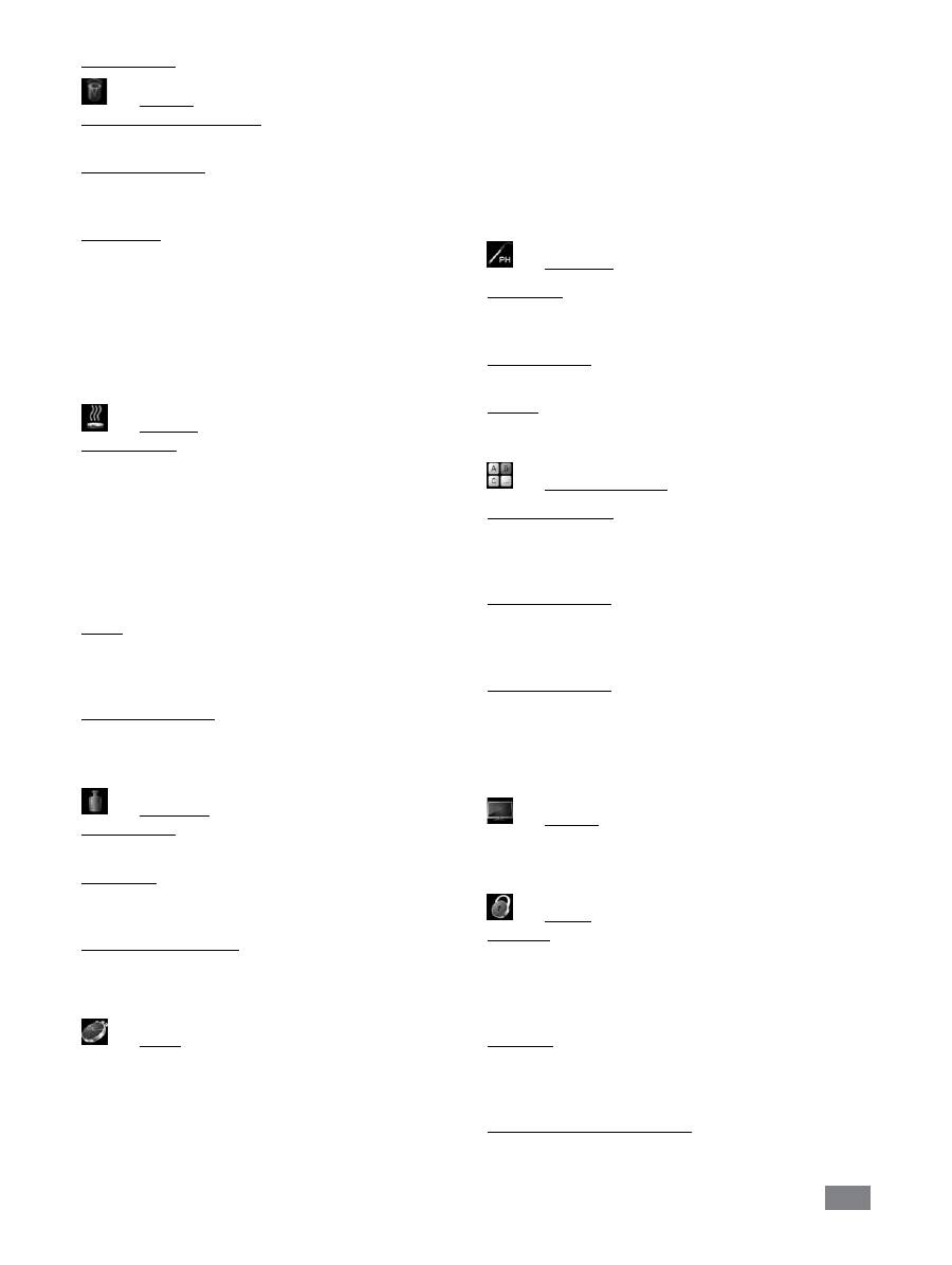
Menu (Details)
Stirring
Torque trend measurement:
Display the torque trend.
Intermittent Mode:
The menu allows the user to activate the “
Run/Stop
“ func
-
tion. The run time and stop time can be set separately.
Speed Limit:
The menu allows the user to set the desired maximum up-
per speed limit for the reactor system. The initial setting is
the maximum permissible speed of the stirrer. If the user
changes this setting, control system of the reactor saves the
new value for future stirring tasks.
If the “
Speed Limit
” has been changed, then the speed can
be adjusted only within the new range.
Heating
Control Mode:
In the menu, the user is allowed to selected “
Accurate
” or
“
Fast
” control mode by rotating and pressing knob (
A
). The
selected control mode is indicated by a tick.
Fast:
reach target temperature quickly but with big over-
shoot and large hysteresis at the beginning.
Accurate:
Reaching the target temperature takes some-
what longer, but for this reason, the initial overshoot and
the hysteresis are significantly smaller.
Limits:
In “
External (ext)
“ option, the user is allowed to set the max
-
imum and minimum temperature for external temperature
control. Confirm and store the setting by pressing on “
OK
“.
Temperature Sensor:
In “
Calibration
“ option, the user is allowed to set calibrate
the external temperature sensor.
Weighing
Measurement:
Start the weighing function here.
Calibration:
The weighing function can be calibrated here with refer-
ence weights.
Reset calibration values:
This option is used to reset the weight reference to the cali-
bration value.
Timer
In the menu the user can specify that the timer is displayed
on the working screen. A tick shows that the option is acti-
vated. This setting allows the user to specify the actual time
for the heating procedure.
A default time can also be set for the timer. This setting al-
lows the user to start the heating task for a standard time.
The device stops automatically after expiry of the set time,
and the set time used for the heating procedure appears in
the display.
Note:
The user can stop the stirring function before expiry
of the set time. In this case the countdown of the timer is
interrupted.
pH Probe
Calibration:
Here you can calibrate the pH probe with the device in con-
nection with the pH buffer solution.
Reset pH probe:
Reset the pH measuring reference to factory default value.
Display:
Display the measured pH value at working screen.
Operating Mode
Operating Mode A:
In this operating mode, the values that were previously set
are saved when the process ends or the device is switched
off. The device does not start again by itself.
Operating Mode B:
In this operating mode, the values that were previously set
are saved when the process ends or the device is switched
off. The device starts again by itself.
Operating mode C:
In this operating mode, the values that were previously set
are saved when the process ends or the device is switched
off. The device starts again by itself. The set values cannot
be changed.
Display
Here the user can specify which information (torque trend,
pH value, timer value) is to be displayed on the working
screen.
Safety
Time Out:
Here you can set a time out. This time out goes into effect
if the communication between the device and the PC has
failed. In this case, the device continues to run with the
set speed and temperature.
Password:
In the menu, the user can protect the device settings using
a password. The user is requested to input the password in
order to access the working screen (factory setting: 000).
Safe temperature confirmation:
Here you must confirm the safety temperature value of the
heating block.

30
Settings
Languages:
Here allows the user to select the desired language by turn-
ing and pressing the rotary/push knob (
A
). A tick indicates
the language that is set for the system.
Display:
Here allows the user to change the background color of the
working screen.
Sound:
Here allows the user to activate/deactivate the key-press
sound and to set the volume.
Factory settings:
Here the user can reset the device to factory settings. The
system requests confirmation to recreate the factory settings.
Pressing the ”
OK
” button resets all the system settings to the
original standard values set at dispatch from the factory (see
"
Fig. 16
").
Information:
The ”
Information
” option offers the user an overview of
the most important system settings of the device.
The device can be operated in “Remote” mode via RS 232 or
USB interface using the laboratory software labworld
soft
®
.
The RS 232 interface at the side of the device is fitted with
a 9-pole SUB-D port which can be connected to a PC. The
pins are assigned serial signals.
The USB port at the side of the device is used for the con-
nection to the PC.
Note:
Please comply with the system requirements togeth-
er with the operating instructions and help section included
with the software.
USB interface
The Universal Serial Bus (USB) is a serial bus system which
allows the stirrer to be connected to the PC. Devices that
support USB can be connected to each other whilst they are
running (hot plugging) and provide automatic recognition
of the connected devices and their properties.
Use the USB interface in conjunction with labworld
soft
®
for
operation in “Remote” mode and for loading the update.
To load the update, open
http://www.ika.com/ika/lws/
download/LR 1000.cfg.
Installation
After the device has been connected with the PC with the
USB data cable, it lets the Windows operating system know
which device driver it needs:
- Load the driver
- Install the driver automatically, if it is not already installed
- Prompt the user to perform a manual installation.
Navigate to
http://www.ika.com/ika/lws/download/st-
mcdc.inf.
Interfaces and output
Serial interface RS 232 (V24)
Configuration
- The functions of the interface connections between the ma-
chine and the automation system are chosen from the sig-
nals specified in EIA standard RS 232 in accordance with DIN
66 020 Part 1.
- For the electrical characteristics of the interface and the
allocation of signal status, standard RS 232 applies in ac-
cordance with DIN 66 259 Part 1.
- Transmission procedure: asynchronous character transmis-
sion in start-stop mode.
- Type of transmission: full duplex.
- Character format: character representation in accordance
with data format in DIN 66 022 for start-stop mode. 1
start bit; 7 character bits; 1 parity bit (even); 1 stop bit.
- Transmission speed: 9600 bit/s.
- Data flow control: none
- Access procedure: data transfer from the stirrer machine to
the computer takes place only at the computer’s request.
Command syntax and format
The following applies to the command set:
- Commands are generally sent from the computer (Master)
to the stirrer machine (Slave).
- The stirrer machine sends only at the computer’s request.
Even fault indications cannot be sent spontaneously from
the stirrer machine to the computer (automation system).
- Commands are transmitted in capital letters.
- Commands and parameters including successive param-
eters are separated by at least one space (Code: hex 0x20).
- Each individual command (incl. parameters and data) and
each response are terminated with Blank CR Blank LF
(Code: hex 0x20 hex 0x0d hex 0x20 hex 0x0A) and have a
maximum length of 80 characters.
- The decimal separator in a number is a dot (Code: hex
0x2E).
31
The above details correspond as far as possible to the rec-
ommendations of the NAMUR working party (NAMUR rec-
ommendations for the design of electrical plug connections
for analogue and digital signal transmission on individual
items of laboratory control equipment, rev. 1.1).
The NAMUR commands and the additional specific
IKA
®
co-
mmands serve only as low level commands for communication
between the machine and the PC. With a suitable terminal or
communications programme these commands can be trans-
mitted directly to the equipment. The
IKA
®
software pack-
age, labworld
soft
®
, provides a convenient tool for controlling
device and collecting data under MS Windows, and includes
graphical entry features, for motor speed ramps for example.
NAMUR Commands
Function
IN_NAME
Input description name
IN_PV_X
X=1;2;3;4;
Reading the real value
IN_SOFTWARE
Input software ID number date, version
IN_SP_X
X=1;2;3;4;6;
Reading the set rated value
IN_TYPE
Input laboratory unit ID
OUT_NAME
Output description name. (Max. 10 characters, default: LR 1000)
OUT_SP_12@n
Setting the WD safety temperature with the echo of the set value
OUT_SP_42@n
Setting the WD safety speed with the echo of the set value
OUT_SP_X n
X=1;2;4;6
Setting the rated value to n
OUT_WD1@m
Watchdog mode 1: When a WD1 event occurs, the heating and shaking functions are
shutdown and message PC 1 is displayed. Set the watchdog time to m (20...1500) seconds,
with echo of the watchdog time. This instruction starts the watchdog function and must be
sent within the set watchdog time.
OUT_WD2@m
Watchdog mode 2: When a WD2 event occurs, the speed setpoint will be set to the WD
safety setpoint speed and the temperature setpoint will be set to the WD safety setpoint
temperature. The PC 2 warning is displayed. The WD2 event can be reset with OUT_WD2@0-
resetting also blocks the watchdog function. Set the watchdog time to m (20...1500)
secondes, with echo of the watchdog time. This command starts the watchdog function and
must be sent within the set watchdog time.
RESET
Switching off the instrument function.
START_X
X=1;2;4
Starting the instrument’s (remote) function
The following table summarises the (NAMUR) commands understood by the
IKA
®
control equipment.
Abbreviations used:
X,y = numbering parameter (integer number)
m =
variable value, integer
n =
value of variable, floating point number
X = 1
Pt100 thermometer (external temperature sensor)
X = 2 temperature (heating block)
X = 3 safety temperature
X = 4 stirring speed
X = 6 safety stirring speed

32
STATUS
Display of status
1S: mode of operation A
2S: mode of operation B
3S: mode of operation C
S0: manual opration without fault
S1: Automatic operation Start (without fault)
S2: Automatic operation Start (without fault)
<0: error code: (-1)
- 1: error 1
- ... (see table)
-31: error 31
-83:wrong parity
-84: unknown instruction
-85:wrong instruction sequence
-86: invalid rated value
-87: not sufficient storage space
STOP_X
X=1;2;4
Switching off the instrument - (remote) function
Variables set with OUT_SP_X are maintained.
“Watchdog” function, monitoring the serial data flow
The following applies to situations where the watchdog function is enabled (see Namur instructions). If no new transmis-
sions of these commands from the PC take place within the preset watchdog time, the heating and shaking functions will
be shutdown according to the watchdog mode selected or will be controlled using the preset setpoints. An operating
system crash, a PC power failure or a fault in the connecting cable to the instrument can cause an interruption in data
transmission.
“Watchdog”– Mode 1
If an interruption in data transmission occurs which is longer than the preset watchdog time, the heating and shaking
functions will be shutdown and the error message PC 1 will be displayed.
“Watchdog”– Mode 2
If an interruption in data transmission occurs which is longer than the preset watchdog time, the speed setpoint value
will be set to the WD safety speed setpoint and the temperature setpoint will be set to the WD safety temperature set-
point. The PC 2 warning message will be displayed.
PC 1.1 Cable
Required for connecting the 9-pin socket to a PC.
1
2 RxD
3 TxD
4
5 GND
6
7 RTS
8 CTS
9
1
RxD 2
TxD 3
4
GND 5
6
RTS 7
CTS 8
9
PC
1
2
3
4
5
6
7
8
9
9
8
7
6
5
4
3
2
1
Fig. 17

33
Maintenance and cleaning
Cleaning
For cleaning disconnect the main plug!
Disassemble the reactor vessel:
Remove the reactor vessel from the LR control base.
Remove the reactor cover from the reactor vessel.
Remove the glass tube from the base as described below.
Use a screwdriver to loosen and remove the four screws on
the two clamps.
Then, both handles can be removed from the glass vessel.
Note:
the screws can only be loosened and can not be re-
moved from the handles.
Now both clamps can be removed. Then remove the glass
tube with handles from the base.
Remove both handles from the glass vessel as following.
Reserve the glass tube with handles. Loosen both screws
with screw driver at the bottom of handles (see
Fig. 19
).
Disassemble the anchor stirrer:
After removing the glass tube from the vessel base, the an-
chor stirrer together with the reactor vessel bottom of the
socket can be taken apart from the vessel base (see
Fig. 20
).
Please pay attention to the O-ring when you disassemble
the reactor vessel.
Open the screw as described in
Fig. 21
with the socket
wrench.
Now you can remove the anchor stirrer as shown in
Fig. 22
.
All O-rings can now be carefully removed by hand or using a
blunt tool for cleaning too.
Fig. 18
Fig. 19
O-ring
Fig. 20
Fig. 21
34
- Wear protective gloves during cleaning the instrument.
- Electrical devices may not be placed in the cleaning agent
for the purpose of cleaning.
- Do not allow moisture to get into the equipment when
cleaning.
- Please consult
IKA
®
before using any cleaning or decon-
tamination methods, other than those recommended here.
- The handles can not be place in the cleaning agent for
cleaning.
- The only cleaners or disinfectants that may be used are
those that:
- lie in the pH range 5 - 8,
- contain no corrosive alkalis, peroxides, chlorine com-
pounds, acids or brine.
Fig. 22
Only clean
IKA
®
appliances using these
IKA
®
approved
cleaning agents.
Dirt
Cleaning agent
Dyes
Isopropanol
Building materials Water containing detergent, Isopropanol
Cosmetics
Water containing detergent, Isopropanol
Food
Water containing detergent
Fuels
Water containing detergent
Other materials
Please consult
IKA
®
Spare parts order
When ordering spare parts, please give:
- machine type
- manufacturing number, see type plate
- item and designation of the spare part see
www.ika.
com
, spare parts diagram and spare parts list.
Repair
Please send equipment for repair only after it has
been cleaned and is free from any materials which
may constitute a health hazard.
For repair, please fill up the “
Decontamination Certifi-
cate
” form supplied with instrument or printed copy on the
IKA
®
website:
www.ika.com
.
If you require servicing, return the equipment in its original
packaging. Storage packaging is not sufficient. Please also
use suitable transport packaging.
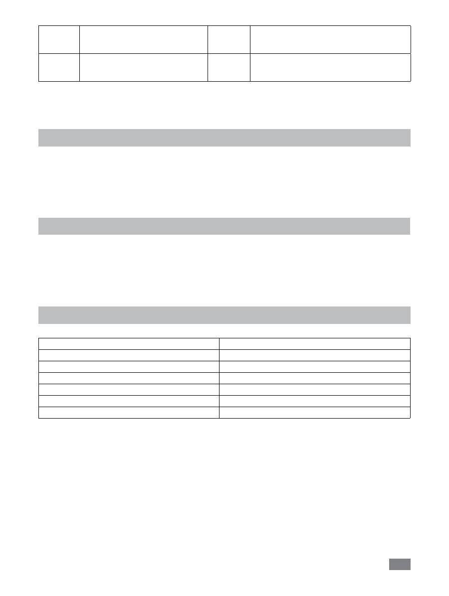
Error codes
The fault is shown by an error message in the display as following if the error occurs.
Proceed as follows in such cases:
Switch off the device using the main switch
Carry out corrective measures
Restart the instrument
Error code Cause
Effect
Corrective action
Error 3
• Permitted ambient temperature has
been exceeded
• Ventilation slots or fan housing is
blocked
Heating off
• Switch off the unit. Allow it to cool down and
then switch on again.
• Clean ventilation slots or fan housing
• Observe maximum permissible ambient
temperature
Error 4
• Motor is blocked or overloaded
Motor off
• Reduce the torque load (load)
• Reduce the setpoint speed
Error 8
• Fault in calibration procedure
• Value was incorrectly stored to
memory
Heating off
• Repeat the calibration procedure
Error 14
• Short-circuit at temperature sensor
plug
• Short-circuit in connecting cable or on
temperature sensor
Heating off
• Check the plug
• Substitude the temperature sensor
35
Accessories
Disperser T 18 digital
Disperser T 25 digital
Disperser adaptor (M36x1.5)
O-ring (Ø 18 x 3.55, FKM)
O-ring (Ø 11.6 x 3, FKM)
Warranty
In accordance with
IKA
warranty conditions, the warranty
period is 24 months. For claims under the warranty please
contact your local dealer. You may also send the machine
direct to our factory, enclosing the delivery invoice and giv-
ing reasons for the claim. You will be liable for freight costs.
Materials in contact with medium/laboratory reactor
Reactor cover
Stainless steel 1.4571 / RCI 316 L
Reactor cover bottom
Stainless steel 1.4571 / RCI 316 L
Reactor vessel
Borosilicate glass 3.3
Anchor stirrer
Stainless steel 1.4571 / RCI 316 L
Scraper
PTFE / Stainless steel 1.4571 / RCI 316 L
O-ring
FKM
Shaft seal
PTFE
O-ring (Ø 41 x 1.9, FKM)
O-ring (Ø 26 x 2, FKM)
Adaptor for PH meter
Anchor Stirrer with PTFE scraper
The warranty does not cover worn out parts, nor does it
apply to faults resulting from improper use, insufficient care
or maintenance not carried out in accordance with the in-
structions in this operating manual.
Error 17
• SAFE Temp is set at a temperature
lower than the actual heating block
temperature
Heating off
• Allow the unit to cool
• Set the SAFE Temp at a higher temperature
Error 26
• Fault in the internal or safety
temperature sensors or measurement
circuit
Heating off
• Substitude the internal and safety temperature
sensor.
If the actions described fails to resolve the fault or another error code is displayed then take one of the following steps:
- Contact the service department
- Send the instrument for repair, including a short description of the fault.

36
Technical data
Nominal voltage
VAC
230 ± 10% (EURO)
Frequency
Hz
50 / 60
Input power
W
1200
Viscosity max.
mPas
100000
Usable volume
ml
300 – 1000
Attainable vacuum
mbar
25
Stirring speed range
rpm
10 – 150
Speed display
TFT
Speed setting resolution
rpm
1
Speed variation
rpm
±5
Heating temperature max. (medium)
°C
120
Temperature display
TFT
Temperature setting resolution
K
0,1
Temperature measurement resolution
K
0,1
Connection for ext. temperature sensor
PT 100
Adjustable safety circuit
°C
50 – 210
Control accuracy with ext. sensor
K
± 0,2
Weighing range
Kg
0 – 2
Weighing resolution
g
1
Cooling medium temperature min.
°C
3
Type of cooling
Liquid through cooling
pH meter interface
yes
pH value display
TFT
Nominal torque
Nm
3
Toque trend display
TFT (relative)
Timer function
yes
Timer display
TFT
USB interface
yes
RS 232 interface
yes
Protection class acc. to DIN EN 60529
IP 21
Permissible ambient temperature
°C
+5 to +40
Permissible ambient humidity (rel.)
%
80
Dimension (W x D x H)
mm
443 x 295 x 360
Weight
kg
16
Operation at a terrestrial altitude
m
max. 2000
Subject to technical changes!
37
Page
Déclaration de conformité CE 37
Explication des symboles
37
Consignes de sécurité
38
Utilisation conforme
39
Déballage 39
Configuration du système
40
Installation
41
Éléments de commande et écran
42
Mise en service
43
Interfaces et sorties
47
Maintenance et nettoyage
50
Codes d’erreur
51
Garantie 52
Accessoires
52
Matières en contact avec le produit
52
Caractéristiques techniques
53
Sommaire
FR
Déclaration de conformité CE
Explication des symboles
Langue d‘origine: allemand
Remarque générale sur un danger
Le présent symbole signale des informations
cruciales pour la sécurité de votre santé
. Leur non-
respect peut provoquer des problèmes de santé ou des blessures.
Le présent symbole signale des informations importantes
pour le bon fonctionnement technique
de l’appareil
. Le non-respect de ces indications peut endommager de l’appareil.
Le présent symbole signale des informations
importantes pour le bon fonctionnement de l’appa
-
reil et pour sa manipulation
. Le non-respect peut avoir pour conséquence des résultats de mesure
imprécis.
Remarque sur une mise en danger en raison d’une surface chaude.
DANGER
CAUTION
AVERTIS-
SEMENT
Nous déclarons sous notre seule responsabilité que ce produit est conforme aux réglementations des directives 2006/42/CE
et 2004/108/CE et est en parfait accord avec les normes et documents normatifs suivants : EN 61010-1, -2-010, -2-051; EN
ISO 12100-1, -2; EN 60204-1 et EN 61326-1.
DANGER

38
• L’indication de la tension de la plaque signalétique doit
coïncider avec la tension du réseau.
Veuillez prendre garde aux dangers ré-
sultant :
- Des matériaux inflammables
- Des milieux combustibles à faible température d’ébullition
- Des récipients en verre
- D’une trop grande quantité d’agent
- De récipients en mauvais état.
• Après une interruption de l’alimentation électrique, l’ap
-
pareil redémarre automatiquement en mode
B
et
C
.
• L’appareil ne doit être ouvert que par un spécialiste,
même en cas de réparation. Avant de l’ouvrir, la fiche
secteur doit être débranchée. Les pièces conductrices à
l’intérieur de l’appareil peuvent rester sous tension même
après une période prolongée après le débranchement de
la fiche secteur.
Les protections et parties de l’appareil
qui peuvent être déposées sans outils
doivent être reposées sur l’appareil pour
garantir un fonctionnement sûr, afin d’empêcher par
exemple la pénétration de corps étrangers, de liquides,
etc.
• Le fonctionnement en conditions de surpression n’est pas
autorisé!
• L’appareil est conçu pour fonctionner en vacuum jusqu’à
25 mbar!
• Veiller à manipuler correctement les dérivés des réactions
et les produits.
• En fonction de l’application et des substances, des dan
-
gers par contact ou inhalation de liquides, gaz, brouil-
lards, vapeurs ou poussières toxiques peuvent exister.
• Les substances biologiques ou microbiologiques peuvent
également engendrer des risques!
• Les outils rotatifs constituent une source de dangers!
• L’agitateur à ancre et l’outil de dispersion ne doivent être
activés que dans une cuve de réaction fermée ! Il est inter
-
dit de mettre le réacteur ouvert en marche!
• La rotation de l’outil de dispersion souillé de produit à l’état
ouvert entraîne la projection d’éléments ou de liquides.
Lorsqu’il fonctionne sous pression nor-
male, le système de réacteur doit tou-
jours être ventilé, afin d’empêcher l’accumulation de pres
-
sion par des gaz très volatils ou par l’évolution inconnue
de la pression de la réaction. Condensez les gaz volatils à
l’aide d’un condenseur à col rodé (par ex. condenseur de
retenue) sur le couvercle du réacteur!
• Veuillez respecter la température maximale tolérée de 230
°C dans la cuve de réaction.
Consignes de sécurité
•
Lisez entièrement le mode d’emploi avant la mise en
service et observez les consignes de sécurité.
• Conservez le mode d’emploi de manière à ce qu’il soit
accessible à tous.
• Veillez à ce que seul un personnel formé travaille avec
l’appareil.
• Respectez les consignes de sécurité, les directives, ainsi
que les mesures de prévention des accidents.
• Un mélange insuffisant d’un matériau chauffé ou une
vitesse de rotation trop élevée, et donc un dégagement
d’énergie accru, peuvent être la cause de réactions incon
-
trôlées. En présence d’un tel danger d’exploitation accru,
l’utilisateur est tenu de prendre les mesures de sécurité
supplémentaires appropriées. Indépendamment de ceci,
IKA
®
recommande aux utilisateurs qui travaillent des ma-
tériaux critiques ou dangereux de sécuriser le montage
d’essai par des mesures supplémentaires appropriées. Il
peut par exemple s’agir de mesures anti-explosions ou
anti-incendie, ou bien des équipements de surveillance
globale. De plus, il convient de veiller à ce que l’interrup-
teur de l’appareil
IKA
®
reste accessible immédiatement,
directement et sans danger.
Si le montage et/ou l’emplacement ne
le permettent pas, il faut prévoir un
in-
terrupteur ARRÊT
supplémentaire facilement accessible
dans la zone de travail.
• Ne traitez que des substances pour lesquelles l’apport
d’énergie pendant l’opération ne pose pas problème.
Ceci s’applique également aux autres apports d’énergie,
par ex. la radiation lumineuse.
• N’utilisez pas l’appareil dans des atmosphères explosives,
avec des matières dangereuses et sous l’eau.
• Ne traitez des matériaux infectieux que sous une hotte
d’aspiration appropriée. En cas de questions, adressez-
vous au service conseil sur les applications d’
IKA
®
.
• Les pieds de l’appareil doivent être propres et ne pas être
abîmés.
• Placez l’appareil à un endroit dégagé sur une surface plane,
stable, propre, non glissante, sèche et non inflammable.
• Évitez les chocs et les coups sur l’appareil ou sur les acces
-
soires.
• Avant chaque utilisation, contrôlez l’état de l’appareil et
des accessoires. N’utilisez pas de pièces endommagées.
• Un travail en toute sécurité n’est garanti qu’avec les ac
-
cessoires décrits dans le chapitre «
Accessoires
».
• En cas de changement d’outil et de montage d’accessoires
autorisés, l’interrupteur de l’appareil doit rester sur
AR-
RET
ou l’appareil doit être débranché du secteur.
• Il n’est possible de couper l’alimentation en courant de l’ap
-
pareil qu’en débranchant la prise secteur ou de l’appareil.
• La prise de courant utilisée pour le branchement sur sec
-
teur doit être facile d’accès.
• La prise utilisée doit être mise à la terre (contact à conduc
-
teur de protection).
DANGER
DANGER
DANGER
AVERTIS-
SEMENT
39
• L’équipement peut chauffer lors de l’agitation.
• Augmentez lentement la vitesse de rotation.
Avant de remplir le récipient de réac-
tion, s’assurer que les réactifs employés
n’endommagent pas le joint d’étanchéi-
té en PTFE et FKM!
• Assurez-vous que 20 mm dans l’agent.la sonde de tem
-
pérature externe soit plongée sur au moins 20 mm dans
l’agent.
• Après le branchement, la sonde de température externe
doit toujours être plongée dans l’agent.
• N’utilisez que des accessoires homologués par
IKA
®
!
• N’utilisez que des pièces de rechange
IKA
®
originales!
Risque de brûlure ! Agissez avec pru
-
dence lorsque vous touchez le bloc
chauffant et le récipient en verre. La chaleur du bloc chauf-
fant peut monter à plus de 230°C et celle du récipient en
verre jusqu’à 120°C. Le couvercle du récipient peut devenir
très chaud lorsque vous faîtes bouillir des liquides pendant
un temps prolongé. Lorsque vous arrêtez l’appareil, veillez
à la chaleur résiduelle.
• Veillez au bon fonctionnement du thermostat utilisé pour
la thermostatisation ! Un thermostat défectueux peut en
-
gendrer une évolution incontrôlée de la réaction!
Avec cet appareil, ne peuvent être trai
-
tés et chauffés que des agents dont le
point d’inflammation dépasse la température de sécurité
limite (50 ... 210 °C). La limite de température de sécurité
fixée doit toujours être au moins de 25 °C inférieure au
point d’inflammation de l’agent utilisé.
•
Utilisation
Le système
IKA
®
LR 1000 control est un système de
réacteur modulaire. Il est spécialement conçu à l’échelle
modèle pour la simulation et l’optimisation de processus
de réactions chimiques ainsi que pour les processus de
malaxage, de dispersion et d’homogénéisation.
Mode de fonctionnement: Appareil de table.
• Champ d’application (uniquement en intérieur)
- Laboratoires
- Écoles
- Pharmacies
- Universités
Utilisation conforme
L’appareil peut être utilisé dans n’importe quel endroit, sauf:
- les zones résidentielles
- les zones directement reliées à un réseau d’alimentation basse
tension qui alimente également des zones résidentielles.
La protection des l’utilisateur n’est plus assurée:
- Si l’appareil est utilisé avec des accessoires non fournis ou
non recommandés par le fabricant
- Si l’appareil est utilisé de manière non conforme, en ne res-
pectant pas les prescriptions du fabricant
- Si des modifications ont été effectuées sur l’appareil ou le
circuit imprimé par un tiers.
DANGER
DANGER
• Déballage
- Déballez l’appareil avec précaution
- En cas de dommages, établissez immédiatement un constat
correspondant (poste, chemin de fer ou transporteur).
• Contenu de la livraison
- LR 1000 control base
- Cuve de réacteur LR 1000
- Câble secteur
- Sonde de température PT 100.5
- Logement de capteur de mesure LR 2000.61
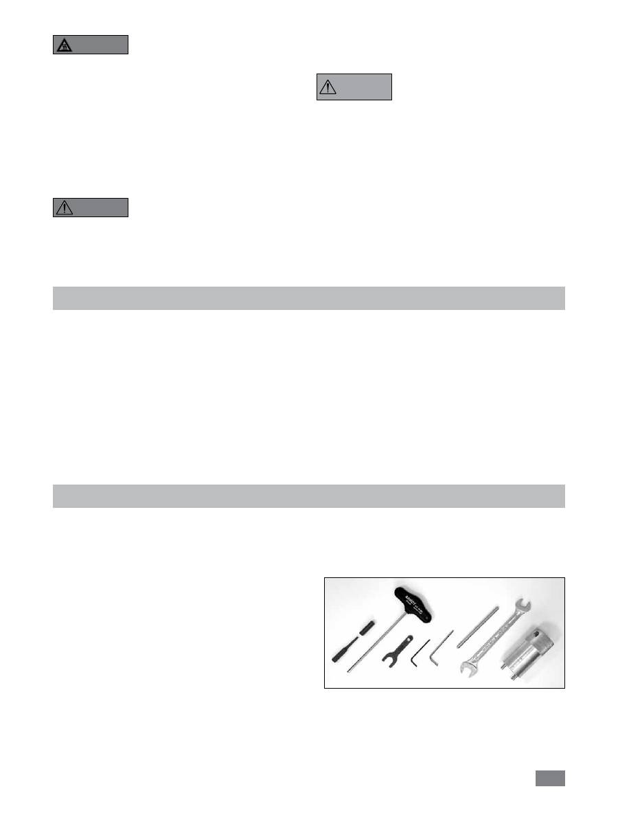
- Kit d’outils
(cf.
Fig. 1
)
- 2 raccords flexibles
Déballage
- Câble USB
- Mode d’emploi
- Carte de garantie
- Certificat de régularité.
AVERTIS-
SEMENT
Fig. 1
40
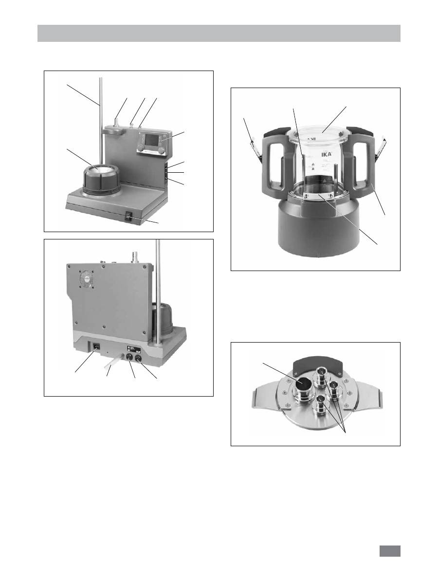
Configuration du système
Le réacteur de laboratoire
IKA
®
LR 1000 control
comporte:
• LR 1000 control base:
A:
interrupteur d’appareil
B:
éléments de commande et écran
C:
bloc chauffant (avec serpentin réfrigérant
intégré pour le branchement de systèmes de
refroidissement externes)
D:
statif pour fixation d’accessoires
E:
douille pour sonde de température
F:
douille pour la sonde de mesure du pH
G:
Logement pour appareil de dispersion (station de
stationnement)
H:
Circuit de sécurité réglable
I:
port USB
J:
port RS 232
K:
prise secteur
L:
tuyau d’évacuation
M*:
Raccord de refroidissement IN
N*:
Raccord de refroidissement OUT
Fig. 2
D
A
C
B
E
F
G
H
I
J
Fig. 3
K
L
M
N
• Cuve de réacteur de laboratoire:
O:
Récipient en verre (verre silicate de bore 3.3)
P:
poignée
R:
fermeture de couvercle
S:
fermeture de récipient
T:
agitateur à ancre
• Système de couvercle pour le réacteur:
U:
NS 29/32
V:
NS 14/23
Fig. 4
O
P
R
S
T
Fig. 5
U
V
*Remarque:
ces raccords ne doivent être utilisés que pour
les besoins de refroidissement.

41
Fixation de la cuve de réacteur sur la LR 1000 control
base
Posez la LR 1000 control une surface plane, stable, propre
et non glissante.
Posez avec précaution la cuve de réacteur sur la LR 1000
control base et assurez-vous qu’elle soit correctement fixée,
comme présenté sur l’illustration ci-après.
Installation
Verrouillage du couvercle du réacteur
Posez avec précaution le couvercle sur la cuve.
Fixez le couvercle à la cuve du réacteur à l’aide des deux
systèmes de verrouillage sur les poignées de la cuve.
Procédez dans le sens inverse pour déverrouiller le couvercle.
Installation et raccordement PT 100
- Enlever un raccord normal NS 14/23 du couvercle du réac-
teur.
- Visser le logement de sonde de mesure avec joint dans le
couvercle du réacteur.
- Brancher la sonde de mesure et veillez à la profondeur
d’immersion minimum et à la course libre de l’agitateur à
ancre. Fixer dans le logement à l’aide des deux vis et de la
butée coulissante.
- brancher la prise dans la douille correspondante.
Raccordement d’un condenseur externe
Le réacteur peut être raccordé via le raccord (
M
,
N
- cf.
Fig. 3
) au dos de l’appareil, à un condenseur externe (par
ex.
IKA
®
KV 600
). Les raccords d’admission et d’évacua-
tion au dos de l’appareil sont signalés en conséquence.
Pour le branchement des tubes de refroidissement, deux
raccords de tuyaux sont prévus à la livraison. Vous pou-
vez raccorder des tuyaux de 10 mm de diamètre intérieur.
Pour déverrouiller les connecteurs, mettez le levier de dé-
verrouillage en position coaxiale et appuyez légèrement
dessus dans le sens de la flèche. Lorsque vous position-
ner les connecteurs de la sorte et les poussez en direc-
tion de la fiche, ces derniers sont verrouillés/raccordés aux
connexions d’admission/d’évacuation du boîtier.
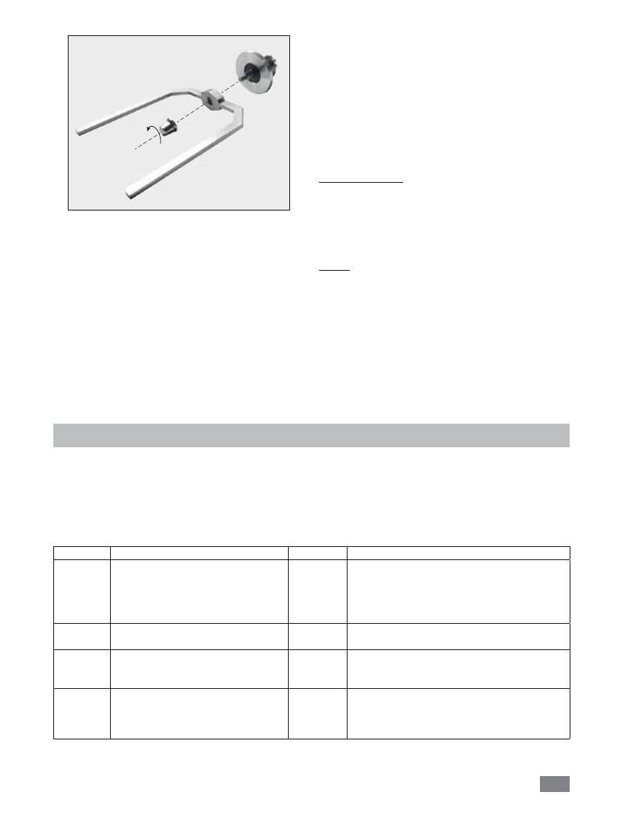
Fixation de l’outil de dispersion dans le couvercle
du réacteur
La tête d’accrochage est nécessaire pour fixer l’arbre de dis
-
persion dans le couvercle du réacteur.
- Placez la bague de sécurité dans la fente, sur l’arbre.
- Enfoncez l’arbre par le bas dans la tête d’accrochage.
- Enfin, placez la bague de sécurité dans la fente supérieure.
- Serrez les boulons de serrage et vissez l’arbre avec la tête
d’accrochage dans le couvercle du réacteur.
CLICK
Déverrouiller
Verrouiller
Fig. 6
Fig. 7
Boulon de serrage
Bague de
sécurité
Fig. 8
Fig. 9
42
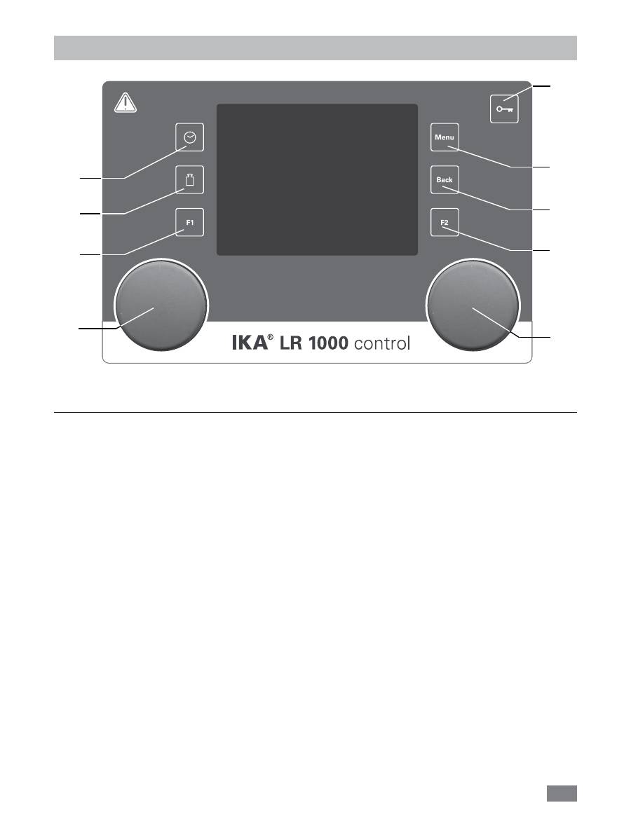
Éléments de commande et écran
Position Désignation
Fonction
A
Bouton rotatif / poussoir:
Active / stoppe la fonction agitation,
Permet de modifier la vitesse de rotation réglée pour l’agitateur sur l’écran de travail,
Sert à naviguer, sélectionner et modifier les paramètres dans le menu.
B
Bouton rotatif / poussoir:
Active / stoppe la fonction chauffage,
Permet de modifier les paramètres de température sur l’écran de travail.
C
Touche “Menu”:
après une seule pression: le menu principal s’affiche.
Après une nouvelle pression : le système revient à l’écran de travail.
D
Touche “Back”:
revient à la fenêtre du menu précédente.
E
Touche minuteur:
active l’affichage du minuteur.
F
Touche Poids:
active l’affichage du poids.
G
Touche à clé:
désactive / active les touches et le bouton rotatif / poussoir..
H
Touche F1:
non utilisé
I
Touche F2:
non utilisé
A
B
C
D
G
E
F
H
I
Fig. 10
