Enerpac ZA4T-Series: инструкция
Раздел: Инструмент, электроинструмент, силовая техника
Тип: Насос
Инструкция к Насосу Enerpac ZA4T-Series
Instruction Sheet
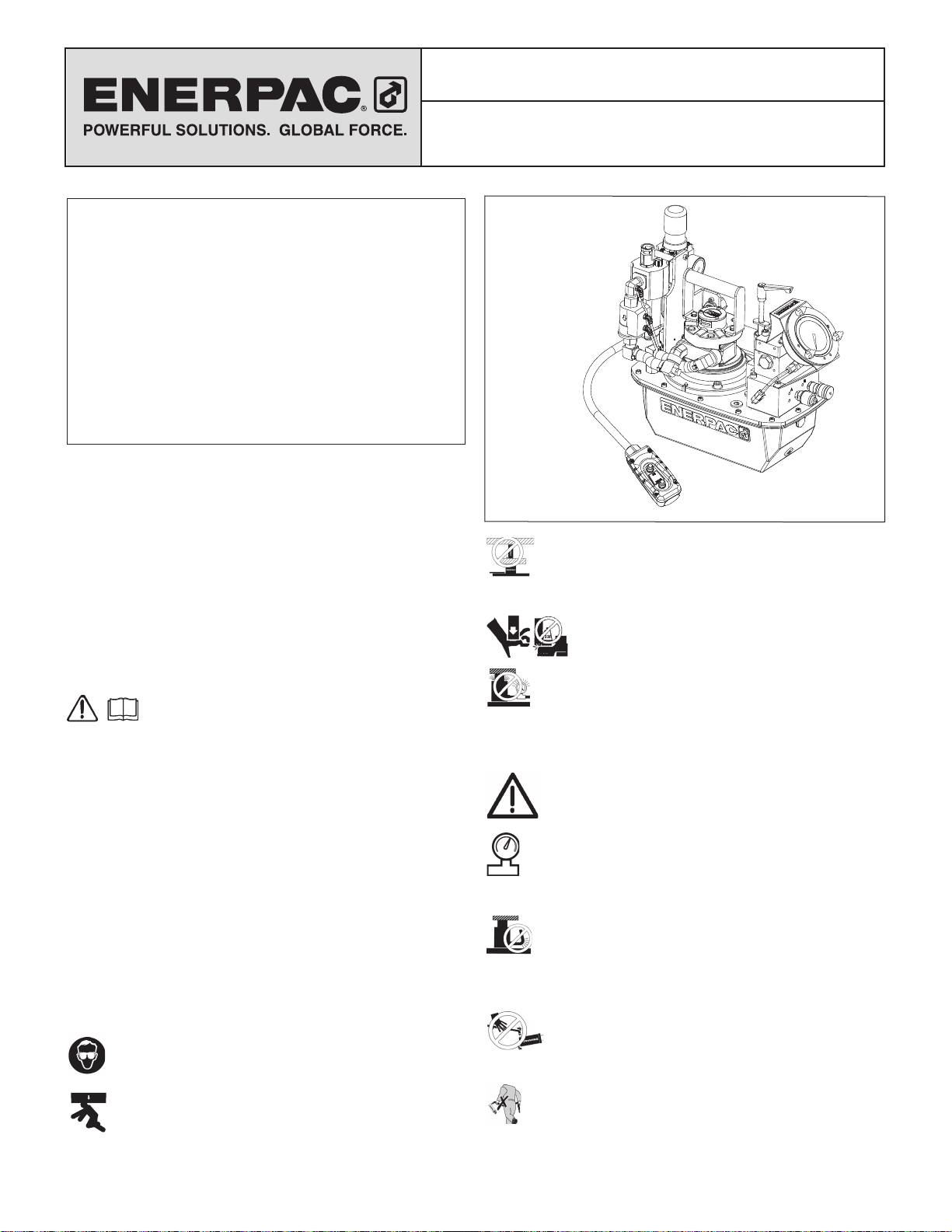
ZA4T Air-Hydraulic Torque Wrench Pump
L2919 Rev. B 10/13
Index:
English. . . . . . . . . . . . . . . . . . . . . . . . . . . . . . . . . . . . . . . . .1-6
Français . . . . . . . . . . . . . . . . . . . . . . . . . . . . . . . . . . . . . . .7-12
Deutsch . . . . . . . . . . . . . . . . . . . . . . . . . . . . . . . . . . . . . .13-18
Italiano. . . . . . . . . . . . . . . . . . . . . . . . . . . . . . . . . . . . . . .19-24
Español . . . . . . . . . . . . . . . . . . . . . . . . . . . . . . . . . . . . . .25-30
Nederlands . . . . . . . . . . . . . . . . . . . . . . . . . . . . . . . . . . .31-36
Portuguese . . . . . . . . . . . . . . . . . . . . . . . . . . . . . . . . . . .37-42
Finnish . . . . . . . . . . . . . . . . . . . . . . . . . . . . . . . . . . . . . . .43-48
Norwegian . . . . . . . . . . . . . . . . . . . . . . . . . . . . . . . . . . . .49-53
Swedish. . . . . . . . . . . . . . . . . . . . . . . . . . . . . . . . . . . . . .54-58
中文 . . . . . . . . . . . . . . . . . . . . . . . . . . . . . . . . . . . . . . . . .59-63
日本語 . . . . . . . . . . . . . . . . . . . . . . . . . . . . . . . . . . . . . . .64-68
Русско. . . . . . . . . . . . . . . . . . . . . . . . . . . . . . . . . . . . . . .69-74
Repair Parts Sheets for this product are available from the
Enerpac web site at www.enerpac.com, or from your nearest
Authorized Enerpac Service Center or Enerpac Sales o ce.
1.0 IMPORTANT RECEIVING INSTRUCTIONS
WARNING: USE ONLY RIGID PIECES TO HOLD
LOADS. Carefully select steel or wood blocks that are
Visually inspect all components for shipping damage. Shipping
capable of supporting the load. Never use a hydraulic
damage is not covered by warranty. If shipping damage is found,
cylinder as a shim or spacer in any lifting or pressing application.
notify carrier at once. The carrier is responsible for all repair and
replacement costs resulting from damage in shipment.
DANGER: To avoid personal injury keep hands
and feet away from cylinder and workpiece
SAFETY FIRST
during operation.
2.0 SAFETY ISSUES
WARNING: Do not exceed equipment ratings. Never
attempt to lift a load weighing more than the capacity of
Read all instructions, warnings and cautions
the cylinder. Overloading causes equipment failure and
carefully. Follow all safety precautions to avoid
possible personal injury. The cylinders are designed for a max.
personal injury or property damage during system
pressure of 700 bar [10,000 psi]. Do not connect a jack or cylinder
operation. Enerpac cannot be responsible for damage or injury
to a pump with a higher pressure rating.
resulting from unsafe product use, lack of maintenance or
incorrect product and/or system operation. Contact Enerpac
Never set the relief valve to a higher pressure than the
when in doubt as to the safety precautions and operations. If you
maximum rated pressure of the pump. Higher settings
have never been trained on high-pressure hydraulic safety,
may result in equipment damage and/or personal injury.
consult your distribution or service center for a free Enerpac
WARNING: The system operating pressure must not
Hydraulic safety course.
exceed the pressure rating of the lowest rated component
Failure to comply with the following cautions and warnings could
in the system. Install pressure gauges in the system to
cause equipment damage and personal injury.
monitor operating pressure. It is your window to what is happening
in the system.
A CAUTION is used to indicate correct operating or maintenance
procedures and practices to prevent damage to, or destruction of
CAUTION: Avoid damaging hydraulic hose. Avoid
equipment or other property.
sharp bends and kinks when routing hydraulic hoses.
A WARNING indicates a potential danger that requires correct
Using a bent or kinked hose will cause severe back-pressure.
procedures or practices to avoid personal injury.
Sharp bends and kinks will internally damage the hose leading to
premature hose failure.
A DANGER is only used when your action or lack of action may
cause serious injury or even death.
Do not drop heavy objects on hose. A sharp impact
may cause internal damage to hose wire strands.
WARNING: Wear proper personal protective gear when
Applying pressure to a damaged hose may cause it
operating hydraulic equipment.
to rupture.
IMPORTANT: Do not lift hydraulic equipment by the
WARNING: Stay clear of loads supported by hydraulics.
hoses or swivel couplers. Use the carrying handle or
A cylinder, when used as a load lifting device, should
other means of safe transport.
never be used as a load holding device. After the load has
been raised or lowered, it must always be blocked mechanically.
1
CAUTION: Keep hydraulic equipment away from
3.0 SPECIFICATIONS
fl ames and heat. Excessive heat will soften packings
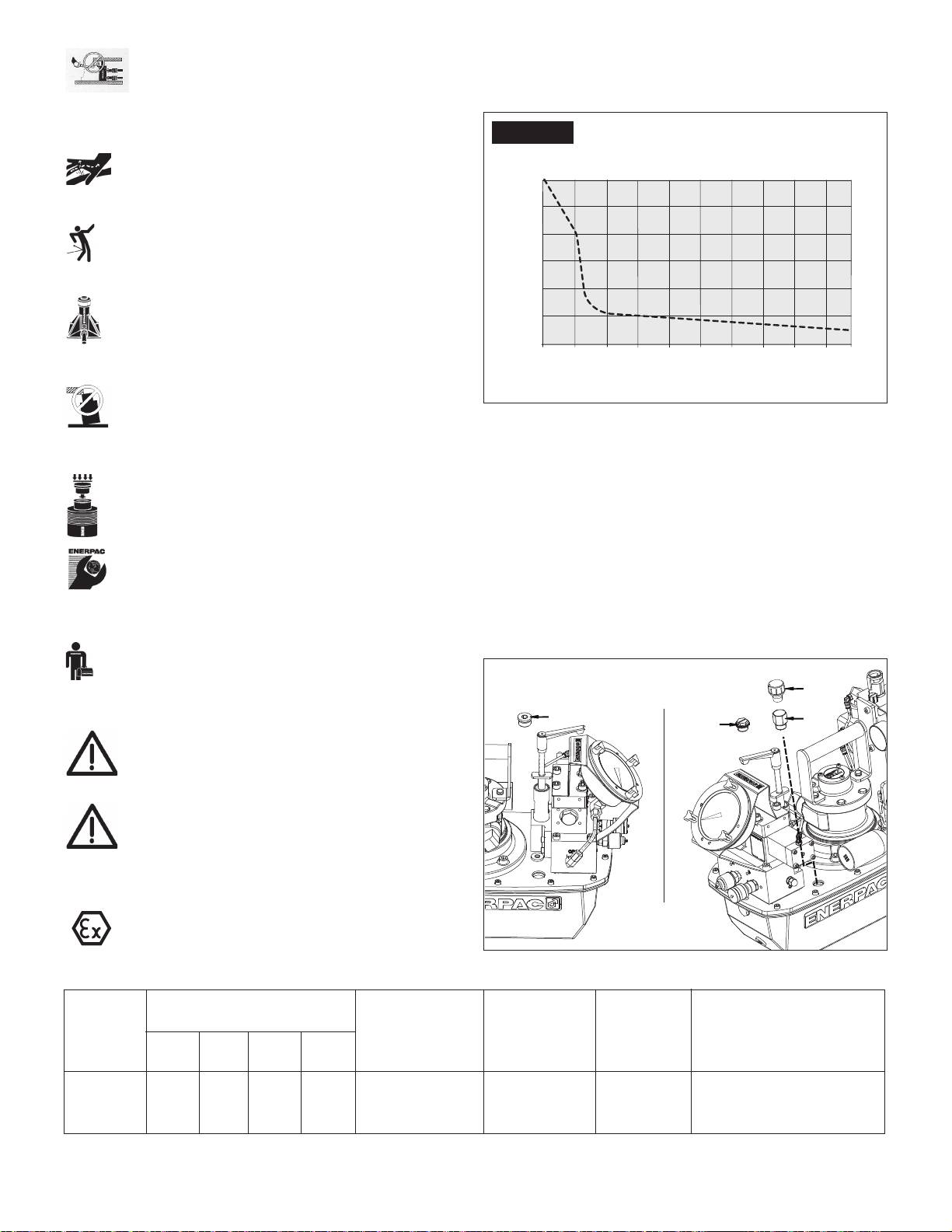
3.1 Performance Chart (see Performance Chart below)
and seals, resulting in fl uid leaks. Heat also weakens
3.2 Flow Chart
hose materials and packings. For optimum performance do not
expose equipment to temperatures of 65°C [150°F] or higher.
Flow vs. Pressure
Figure 1
Protect hoses and cylinders from weld spatter.
100 psi dynamic air pressure
DANGER: Do not handle pressurized hoses. Escaping
@ 70 scfm air consumption standard mu er
oil under pressure can penetrate the skin, causing
serious injury. If oil is injected under the skin, see a
doctor immediately.
WARNING: Only use hydraulic cylinders in a coupled
/min)
system. Never use a cylinder with unconnected couplers. If
3
the cylinder becomes extremely overloaded, components
can fail catastrophically causing severe personal injury.
Flow (in
WARNING: BE SURE SETUP IS STABLE BEFORE
LIFTING LOAD. Cylinders should be placed on a fl at
surface that can support the load. Where applicable, use
a cylinder base for added stability. Do not weld or otherwise
modify the cylinder to attach a base or other support.
Pressure (psi)
Avoid situations where loads are not directly centered
on the cylinder plunger. O -center loads produce
Figure 1
considerable strain on cylinders and plungers. In
addition, the load may slip or fall, causing potentially dangerous
4.0 INSTALLATION
results.
Distribute the load evenly across the entire saddle
Install or position the pump to ensure that air fl ow around the
surface. Always use a saddle to protect the plunger.
motor and pump is unobstructed. Keep the motor clean to ensure
maximum cooling during operation.
4.1 Breather Cap and Oil Fill Plug (See Figure 2)
IMPORTANT: Hydraulic equipment must only be
A shipping plug (A) is installed in the breather port on the top of
serviced by a qualifi ed hydraulic technician. For repair
the reservoir. Before using the pump, replace the shipping plug
service, contact the Authorized ENERPAC Service
(A) with the breather cap (B) and adapter fi tting (C). Note: The oil
Center in your area. To protect your warranty, use only
fi ll port is located on the opposite side of the pump. The oil fi ll
ENERPAC oil.
port uses an SAE #10 plug (D).
WARNING: Immediately replace worn or damaged parts
with genuine ENERPAC parts. Standard grade parts will
break causing personal injury and property damage.
ENERPAC parts are designed to fi t properly and withstand high
loads.
WARNING: Start the pump with the valve in the
neutral position to prevent accidental cylinder
operation. Keep hands clear of moving parts and
pressurized hoses.
WARNING: These pumps have internal factory
adjusted relief valves, which must not be repaired or
adjusted except by an Authorized Enerpac Service
Center.
Figure 2, Oil Fill Plug and Breather Cap
2
D
600
500
400
300
200
100
0
0 1000 2000 3000 4000 5000 6000 7000 8000 9000 10000
B
C
A
II 2 GD ck T4
▼ ZA4T PERFORMANCE CHART
Motor
Output Flow Rate
Dynamic Air
Air
Sound Level
Relief Valve
Size
in
3
/min
Pressure Range
Consumption
@ 100 psi
Adjustment
dynamic
Range
(hp)
100 700 5,000 10,000
(psi)
(scfm)
(dBA)
(psi)
psi psi psi psi
4*
600 500 80 60
60-100
20-100
80-95
1,400-10,000 for "Q" version
1,400-11,600 for "E" version
*Actual power consumption depends on the application. See Figure 1.
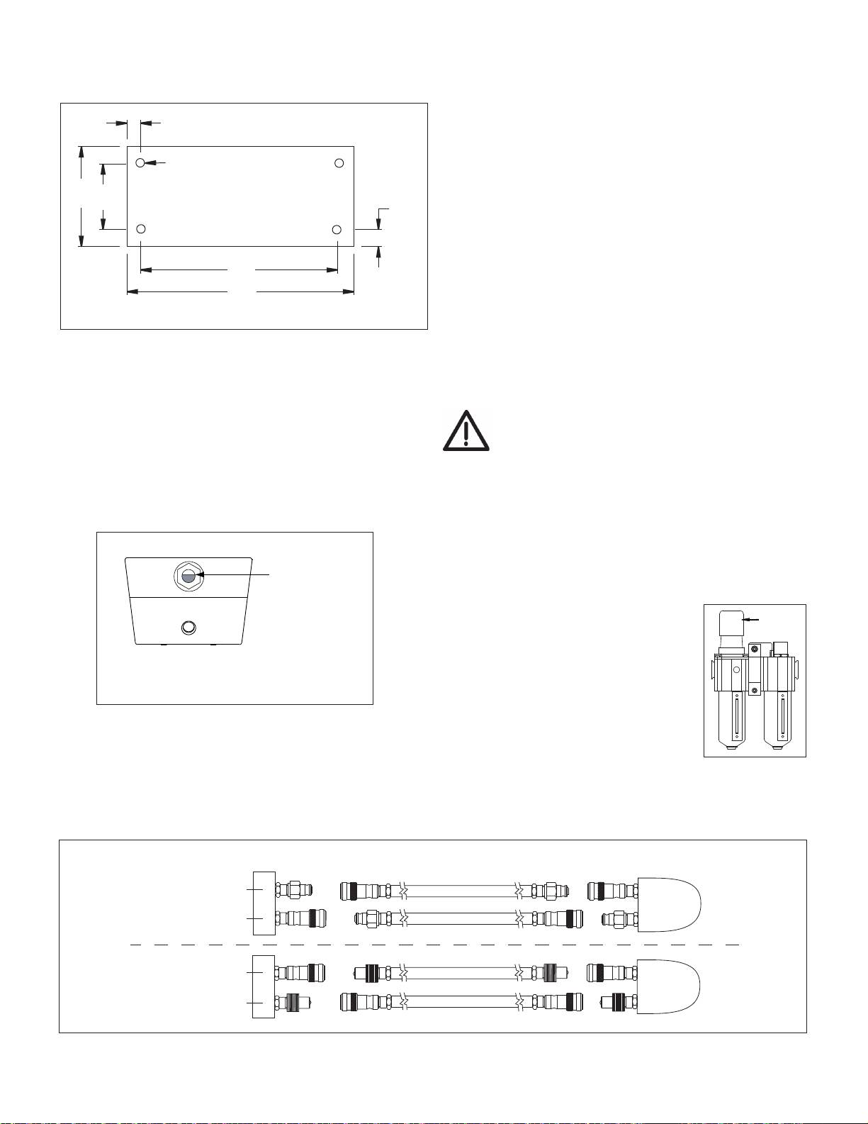
4.2 Pump Mounting
4.5 Connect Hydraulic Hoses
Refer to Figure 3 for mounting dimensions to secure the pump to
Connect hoses as shown in Figure 5.
a fi xed surface.
1. (-E) Pump type for Enerpac SQD and HXD torque wrenches.
Be sure to use hoses marked “ENERPAC THC-700 SERIES
3.64
- 800 Bar/11,600 psi max.” The couplers on these hoses are
“polarized” at the factory to ensure correct wrench operation.
(See fi gure 5.)
M8 x 1.25
A. Hose and wrench female couplers. Hand tighten threaded
.25 deep
coupler lock rings, no tools are required.
9.46
3.75
B. The (-E) pump’s female couplers are self locking, press
2.86
mating couplers together until coupler lock ring snaps
forward. To disconnect, twist coupler lock ring clockwise and
push away from connection.
9.00
2. (-Q) Pump type for Enerpac S and W torque wrenches
and other brands. Use hoses marked "Enerpac THQ-700
16.28
series-700 bar/10,000 psi max.". Couplers must be polarized
per fi gure 5 for correct wrench operation. Ensure couplers are
fully engaged and tightened before operating. Partial coupler
Figure 3
engagement will prevent proper wrench operation.
4.6 Filling Air Lubricator
4.3 Air Supply Connections
Fill lubricator reservoir with a light misting type oil suitable for
Pump requires 60-100 psi dynamic air pressure at 20-100 cfm.
compressed air tools.
Attach incoming air supply to the 1/2" NPT port on the regulator/
CAUTION: Maintaining the lubricator oil level is critical
fi lter/lubricator.
to the life of the pump.
4.4 Fluid Level
Check the oil level of the pump prior to start-up, if necessary add
4.7 Air Lubricator Adjustment
oil by removing the SAE #10 plug from the cover plate (see Fig. 2).
The reservoir is full when the oil level reaches the top of the sight
The adjustment screw (E) is factory-adjusted fully clockwise, so no oil
glass. (Fig. 4).
is delivered to lubricate the system. To make initial adjustment, turn
on the air and start fl ow to the system. Turn knob to adjust oil drip
rate. Turning knob counter-clockwise increases drip rate. (see Fig. 6)
Set the drip rate to one or two drops per minute initially and fi ne tune
Tank is full
the rate after the system reaches its normal operating temperature.
when oil level
To check lubrication, hold a mirror near the equipment exhaust. If
is here.
a heavy fi lm develops, reduce lubrication.
E
4.8 Air Pressure Regulator Adjustment
Pull knob straight up to unlock. The
4 and 8 liter
adjustment knob must be turned clockwise
to increase and counter-clockwise to
decrease outlet pressure setting. To reduce
pressure, fi rst reduce to a pressure less than
Figure 4
that desired, then increase to the desired
outlet pressure.
(See fi gure 6.)
IMPORTANT: Add oil only when all system components are fully
Figure 6
retracted, or the system will contain more oil than the reservoir
can hold.
Torque WrenchPump Valve
Retract
(-E) Pumps
B
ENERPAC THC-700 SERIES - 800 BAR/11,600 PSI MAX.
Advance
A
ENERPAC THC-700 SERIES - 800 BAR/11,600 PSI MAX.
Retract
B
ENERPAC THC-700 SERIES - 700 BAR/10,000 PSI MAX.
(-Q) Pumps
Advance
A
ENERPAC THC-700 SERIES - 700 BAR/10,000 PSI MAX.
Figure 5
3
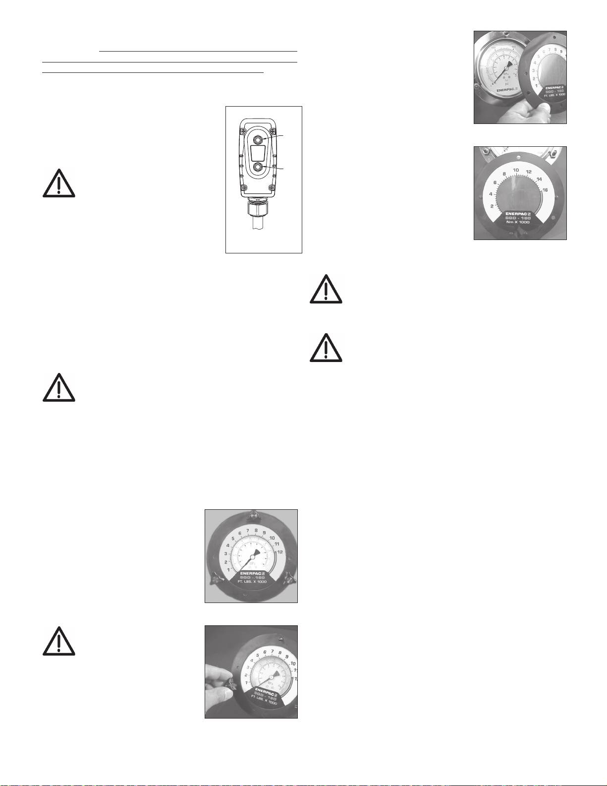
5.0 OPERATION
2. Remove the front fl ange and
overlay (see Fig. 10.)
IMPORTANT: When possible, a single user should operate the
torque wrench and pump. This can prevent accidental activation
3. Insert new overlay (remember to
of the pump while the operator is positioning the wrench.
verify correct overlay to the Enerpac
torque wrench being used) onto the
1. Check all system fi ttings and connections to be sure they are
fl ange, aligning the overlay with the
tight and leak free.
dimples on the back of the fl ange
2. Check oil level in reservoir and add oil
(see Fig. 11).
if necessary. (see section 4.4)
4. While holding the overlay behind the
F
Figure 10
3. Make sure the shipping plug has
fl ange (see Fig. 10.) insert the fl ange
been removed and the breather cap is
ON/ADV
onto the knob studs, repositioning
installed. (see section 4.1)
OFF
the overlay as needed, and secure
G
knobs fi nger tight (see Fig. 9).
WARNING: In the following
The fl ange will press the overlay
step, the pump motor will start
onto the gauge and secure it
and the valve will shift
in place. See torque wrench
automatically, retracting the torque
instructions for amount of pressure
wrench. Verify torque wrench is positioned
required to produce desired torque.
to avoid injury or equipment damage
Note that the maximum pressure
before starting motor.
Figure 7
varies for di erent wrenches and
Figure 11
4. To start the pump, press the green
accessories.
"ON/ADV" button (F) on the pendant (handset). The wrench
will advance as long as the green button is held down.
CAUTION: Refer to torque wrench instructions for
5. Release the green button to retract the wrench. The motor will
wrench operating procedure.
remain "ON".
6. Press the red "OFF" button (G) on the pendant to stop the
pump motor.
5.4 Pressure (Torque) Setting
7. To release hydraulic pressure on the wrench and hoses, press
WARNING: Make these adjustments BEFORE putting
and hold the red "OFF" button. Press and release the green
torque wrench on nut or bolt head. The pump pressure
"ON/ADV" button 3 or more times until the pressure gauge
setting may not be above the pressure needed to
reads 0 pressure. The hoses can now be removed.
provide the required torque for your application. Exceeding
CAUTION: MAKE SURE THE MOTOR IS TURNED
required torque will cause equipment damage and may lead to
OFF AND IS NOT RUNNING BY PRESSING THE RED
serious personal injury.
"OFF" BUTTON, BEFORE THE AIR SUPPLY SOURCE
To limit the advance pressure to the torque wrench, adjust the
IS TURNED OFF OR DISCONNECTED.
relief valve as described in the following procedure. See Figure 12.
5.1 Air Removal
1. Loosen the relief valve locking nut.
When the wrench is fi rst connected to the pump, air will be trapped
2. Rotate relief valve handle counter-clockwise as required, until
in the components. To ensure smooth and safe operation, remove
there is little or no resistance when turning. When this occurs,
air by cycling wrench several times without load. Cycle until
the valve is at its lowest setting.
wrench advances and retracts without hesitation.
Note: Relief valve handle will rotate only about two thirds of a full
Check oil level before operation.
turn. When rotation stops, pull up on handle to disengage. Then,
5.2 Gauge and Overlay Operation Procedure
reposition and re-engage handle to allow additional adjustment
The pump is supplied with a
(as required).
pressure gauge installed. For your
3. Press and hold the pendant “ON/ADV” button. Motor will start
convenience, torque overlays are
and pressure will begin building in the A-Port advance circuit.
provided with each pump. A torque
4. While continuing to hold down the “ON/ADV” button, SLOWLY
overlay fi ts over the pressure gauge
rotate relief valve handle clockwise, until pressure increases
dial face and easily converts pressure
to the desired setting.
readings to torque readings (see Fig.
8). The overlay has imperial units (Ft-
Note: To obtain an accurate setting, always decrease the pressure
Lbs.) on one side and metric units
to a point below the fi nal setting and then slowly increase the
(Nm) on the other. To change scales
pressure until the fi nal setting is reached.
Figure 8
simply slip overlay over.
5. Release the “ON/ADV” button to allow the system pressure to
WARNING: Each overlay
return to the B-port retract setting. The motor will continue to
is sized for a specifi c
run.
Enerpac torque wrench
6. Press and hold the “ON/ADV” button again to recheck the
ONLY. Do not use with other
advance circuit pressure setting. Verify that the desired
wrenches.
pressure is indicated on the pressure gauge.
5.3 Changing the Overlay
7. After the desired pressure setting has been obtained, tighten
the relief valve locking nut.
1. Remove the three black wing
knobs which hold the front
gauge fl ange in place (see Fig. 9).
Figure 9
4
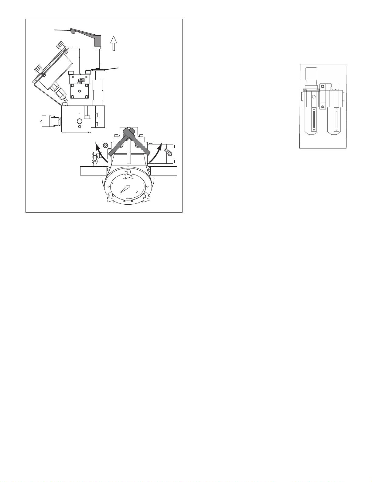
6.3 Cleaning the Mu er
Handle
When the pump is run for long periods of time, ice may form on
the mu er element and must be removed. To clean the mu er,
unscrew and remove any debris.
Pull up to
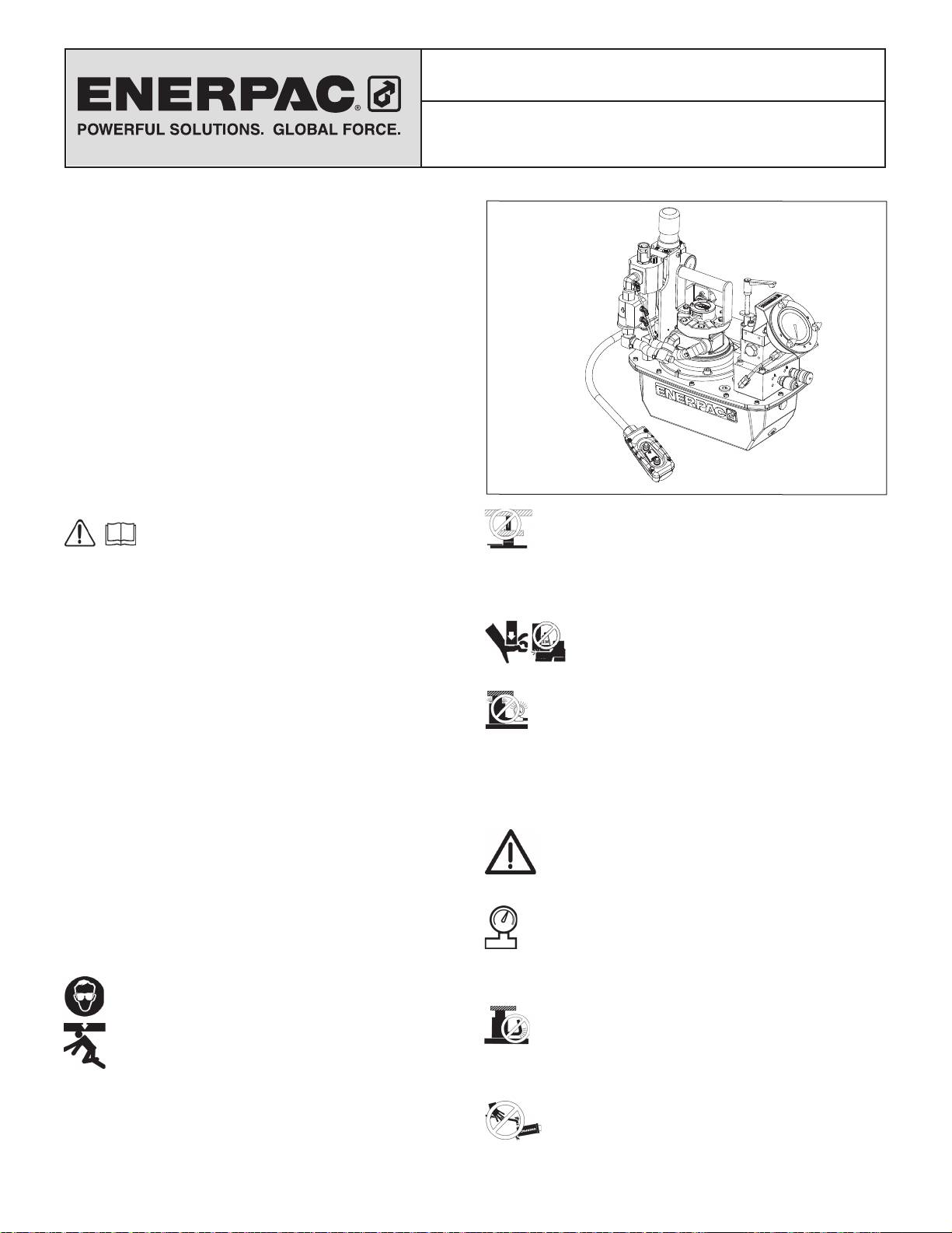
6.4 Cleaning the Air-Filter Lubricator
disengage
Inspect the air-fi lter lubricator frequently to detect for damage.
Locking Nut
Replace damaged bowls.
Keep the fi lter bowl clean to maintain
fi ltering e ciency. The unit is equipped
with an automatic drain, which
opens around 3 psig and closes at
approximately 5 psig. (See Figure 13.)
A visible coating of dirt or condensate
on the fi lter element or an excessive air
pressure drop indicates that cleaning
is necessary. Depressurize the unit
before removing bowl for cleaning.
Figure 13
CAUTION: Clean fi lter bowl with
household soap only.
7.0 TROUBLESHOOTING (SEE TROUBLE-SHOOTING
Increase
Decrease
GUIDE)
Only qualifi ed hydraulic technicians should service the pump or
system components. A system failure may or may not be the result
of a pump malfunction. To determine the cause of the problem, the
complete system must be included in any diagnostic procedure.
The following information is intended to be used only as an aid in
Figure 12, Relief Valve Adjustment
determining if a problem exists. For repair service, contact your
local Authorized Enerpac Service Center.
6.0 MAINTENANCE
Frequently inspect all system components for leaks or damage.
Repair or replace damaged components.
6.1 Check Oil Level
Check the oil level of the pump prior to start-up, and add oil, if
necessary, by removing the fi ll port cap. Always be sure hydraulic
wrenches are fully retracted before adding fl uid to the reservoir.
See Figure 2.
6.2 Change Oil and Clean Reservoir
Enerpac HF oil is a crisp blue color. Frequently check oil condition
for contamination by comparing pump oil to new Enerpac oil. As
a general rule, completely drain and clean the reservoir every 250
hours, or more frequently if used in dirty environments.
NOTE: This procedure requires that you remove the pump from
the reservoir. Work on a clean bench and dispose of used oil
according to local codes.
1. Unscrew the 13 bolts holding the coverplate to the reservoir
and lift the pump unit out of the reservoir. Be careful not to
damage the fi lter screen.
2. Pour all oil out of the reservoir.
3. Thoroughly clean the reservoir and reservoir magnet with a
suitable cleaning agent.
4. Remove the pick-up fi lter screen for cleaning. (Do not pull
on the screen or the bottom of the intake to avoid possible
damage.) Clean the screen with solvent and a soft brush.
Reinstall.
5. Reassemble the pump and reservoir, installing a new reservoir
gasket.
6. Fill the reservoir with clean Enerpac hydraulic oil. The reservoir is
full when oil level is in middle of the sight gauge (see fi gure 4).
5

Trouble-shooting Guide
Problem
Possible Cause
Action
Pump will not start
Air turned o or line blocked
See section 5.0 Operation for details
Motor stalls under load
Low air pressure
See section 4.8
Mu er plugged; contaminated air
Reduce load or add cylinder capacity
Check hydraulic couplers for full engagement
Pump fails to build pressure or less
Low oil level
Add oil per section 4.4
than full pressure
Relief valve set too low
Adjust per section 5.4
External system leak
Inspect and repair or replace
Internal leak in pump
See authorized service center
Internal leak in valve
See authorized service center
Internal leak in system component
See authorized service center
Wrench will not retract
Valve malfunction
See authorized service center
Return fl ow line restricted or blocked
Check couplers for full engagement
Low oil fl ow rate
Inadequate air supply
See Section 4.3
Dirty air fi lter
See Section 6.4
Clogged inlet fi lter
See Section 6.4
6
Fiche d’instructions
ZA4T Pompe air-hydraulique
pour clés dynamo métrique
L2919 Rev. B 10/13
Les vues éclatées de ce produit sont disponibles sur le site
Enerpac www.enerpac.fr. Vous pouvez également les obtenir
auprès de votre réparateur agréé Enerpac ou auprès d'Enerpac
même.
1.0 INSTRUCTIONS IMPORTANTES RELATIVES À LA
RÉCEPTION
Inspecter tous les composants pour vous assurer qu’ils n’ont
subi aucun dommage en cours d’expédition. Les dommages
subis en cours de transports ne sont pas couverts par la garantie.
S’il sont abîmés, aviser immédiatement le transporteur, qui est
responsable des frais de réparation et de remplacement résultant
de dommages en cours de transport.
LA SÉCURITÉ AVANT TOUT !
2.0 SÉCURITÉ
Lire attentivement toutes les instructions et mises
AVERTISSEMENT : UTILISER SEULEMENT DES
en garde et tous les avertissements. Suivre toutes
PIÈCES RIGIDES POUR SOUTENIR LES CHARGES.
les précautions pour éviter d’encourir des blessures
Sélectionner avec précaution des blocs d’acier ou de
personnelles ou de provoquer des dégâts matériels durant le
bois capables de supporter la charge. Ne jamais utiliser un vérin
fonctionnement du système. Enerpac ne peut pas être tenue
hydraulique comme cale ou intercalaire d’appui pour les
responsable de dommages ou blessures résultant de l’utilisation
applications de levage ou de pressage.
risquée du produit, d’un mauvais entretien ou d’une application
DANGER: : Pour écarter tout risque de blessure
incorrecte du produit et du système. En cas de doute sur les
personnelle, maintenir les mains et les pieds à
précautions ou les applications, contacter Enerpac. En l’absence
l’écart du vérin et de la pièce à usiner durant
d’une formation aux mesures de sécurité à prendre en présence
l’utilisation.
de liquides sous haute pression, consulter un centre de
AVERTISSEMENT : Ne pas dépasser les valeurs
distribution ou de réparation Enerpac pour suivre un cours gratuit
nominales du matériel. Ne jamais essayer de soulever
sur ce thème.
une charge d’un poids supérieur à la capacité du vérin.
Respecter les mises en garde et avertissements suivants sous
Une surcharge entraînera la panne du matériel et risque de
peine de provoquer des dégâts matériels et des blessures
provoquer des blessures personnelles. Les vérins sont conçus
personnelles.
pour une pression maximale de 700 bar. Ne pas connecter de
Une mise en garde ATTENTION sert à indiquer des procédures
cric ou de vérin à une pompe a chant une pression nominale
d’utilisation et de maintenance correctes qui visent à empêcher
supérieure.
l’endommagement voire la destruction du matériel ou d’autres
Ne jamais régler la soupape de sûreté à une pression
dégâts.
supérieure à la pression nominale maximale de la pompe
Un AVERTISSEMENT indique un danger potentiel qui exige la
sous peine de provoquer des dégâts matériels et/ou des
prise de mesures particulières visant à écarter tout risque de
blessures personnelles.
blessure.
AVERTISSEMENT : La pression de fonctionnement du
La mention DANGER n’est utilisée que lorsqu’une action ou un
système ne doit pas dépasser la pression nominale du
acte de négligence risque de causer des blessures graves, voire
composant du système a chant la plus petite valeur.
mortelles.
Installer des manomètres dans le système pour surveiller la
pression de fonctionnement. Ils permettent de vérifi er ce qui se
AVERTISSEMENT : Porter un équipement de protection
passe dans le système.
personnelle adéquat pour utiliser un appareil hydraulique.
ATTENTION : Éviter d’endommager les tuyaux
AVERTISSEMENT : Rester à l’écart de charges
hydrauliques. Éviter de les plier et de les tordre en les
soutenues par un mécanisme hydraulique. Un vérin,
mettant en place. Un tuyau plié ou tordu entraînera un fort retour
lorsqu’il est utilisé comme monte-charge, ne doit jamais
de pression. Les plis et coudes prononcés endommageront par
servir de support de charge. Après avoir monté ou abaissé la
ailleurs l’intérieur du tuyau, provoquant son usure précoce.
charge, elle doit être bloquée par un moyen mécanique.
Ne pas faire tomber d’objets lourds sur le tuyau. Un
fort impact risque de causer des dégâts intérieurs
(torons métalliques). L’application d’ une pression sur
un tuyau endommagé risque d’entraîner sa rupture.
7
Оглавление
- II 2 GD ck T4
- II 2 GD ck T
- II 2 GD ck T4
- II 2 GD ck T
- II 2 GD ck T4
