Enerpac EPH-Series: инструкция
Раздел: Инструмент, электроинструмент, силовая техника
Тип:
Инструкция к Enerpac EPH-Series
Instruction Sheet
POWERFUL SOLUTIONS. GLOBAL FORCE.
Posi Lock Puller System
L1697 Rev. B 05/14
IMPORTANT RECEIVING INSTRUCTIONS
Visually inspect all components for shipping damage. If any shipping damage is found, notify
carrier at once. Shipping damage is NOT covered by warranty. The carrier is responsible for all
repair or replacement cost resulting from damage in shipment.
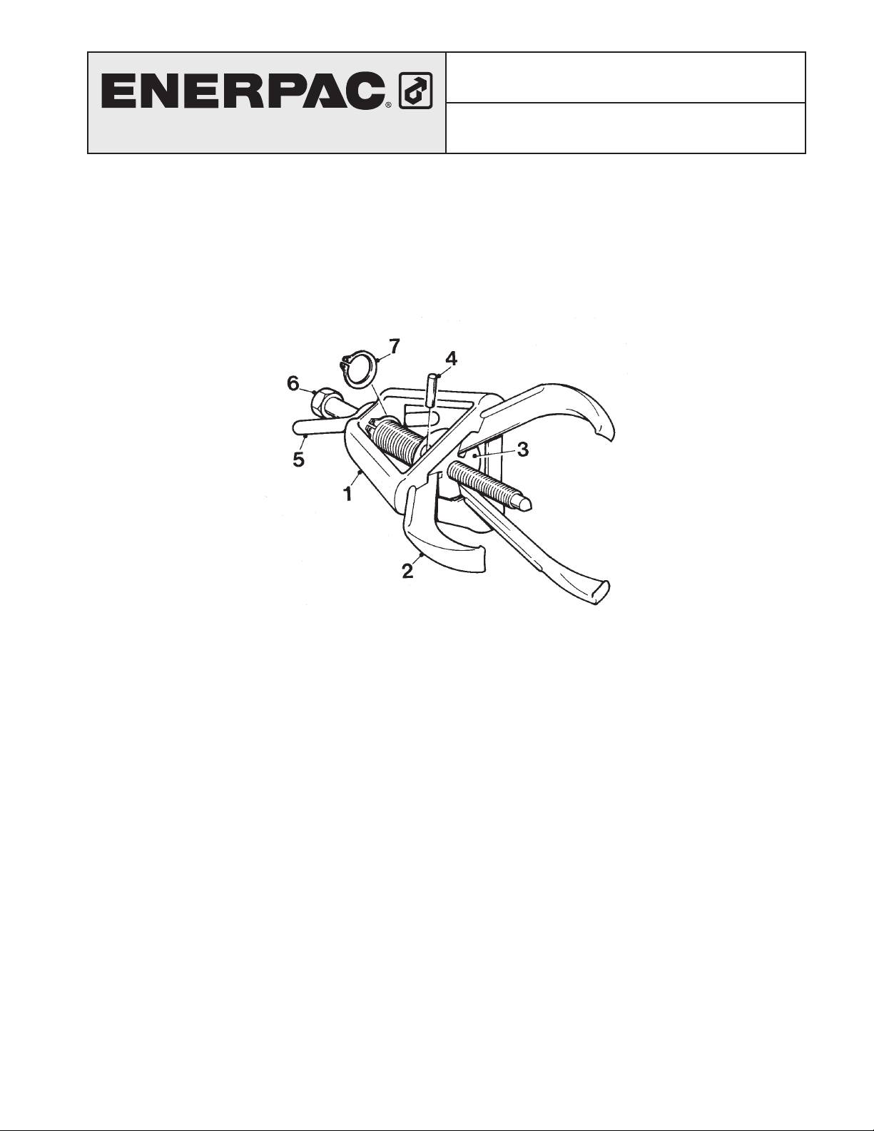
Figure 1, Components of Posi Lock Puller
(see page 50 for parts list)
DESCRIPTION
The Enerpac Posi Lock Puller System is manually or hydraulically operated. The puller consists
of a control cage (item 1), jaw (item 2), jaw-head assembly (item 3), ball lock pins (item 4),
T-handle (item 5), center bolt (item 6), and a snap ring (item 7). The control cage holds the puller
jaws securely in any position. Operating, closing, locking, and aligning the jaws is done by turn-
ing the T-Handle. In hydraulic pullers, the center bolt is replaced by a hydraulic cylinder.
The 100 ton puller comes with an electrically powered lift cart, enabling the puller to be raised
up to 5 feet above ground.
CONTENTS
English . . . . . . . . . . . . . . . . . . . . . . . . . . . . . . . . . . . . . . . . . . . . . . . . . . . . . . . . . . . 1
Deutsch . . . . . . . . . . . . . . . . . . . . . . . . . . . . . . . . . . . . . . . . . . . . . . . . . . . . . . . . . . 8
Français . . . . . . . . . . . . . . . . . . . . . . . . . . . . . . . . . . . . . . . . . . . . . . . . . . . . . . . . . . 15
Español . . . . . . . . . . . . . . . . . . . . . . . . . . . . . . . . . . . . . . . . . . . . . . . . . . . . . . . . . . 22
Italiano . . . . . . . . . . . . . . . . . . . . . . . . . . . . . . . . . . . . . . . . . . . . . . . . . . . . . . . . . . . 29
Nederlands . . . . . . . . . . . . . . . . . . . . . . . . . . . . . . . . . . . . . . . . . . . . . . . . . . . . . . . . 36
Русский . . . . . . . . . . . . . . . . . . . . . . . . . . . . . . . . . . . . . . . . . . . . . . . . . . . . . . . . . . 43
(1)
SAFETY INFORMATION
WARNING
Do not overload cylinder. Do not exceed clamping forces. Overloading causes
equipment failure and possible personal injury. Use hydraulic gauges to ensure proper
operating pressure in each hydraulic system. Do NOT exceed maximum pressure
limits of lowest rated component in your system. Always use high pressure hoses and
fittings.
WARNING
Do not over-extend the cylinder. Do not operate beyond limits of its rated stroke. It
will cause unnecessary strain to the cylinder.
WARNING
AVOID SHARP BENDS AND KINKS IN HOSES. The oil flow will be restricted
causing severe back-pressure. Sharp bends and kinks will internally damage
hoses leading to premature failure.
WARNING
WEAR SAFETY GLASSES to protect your eyes against injury.
WARNING
KEEP FINGERS AWAY. During operation, keep hands and fingers away from the
operation area to avoid personal injury.
INSTALLATION
Selection guide
When determining which puller to use, follow these guidelines:
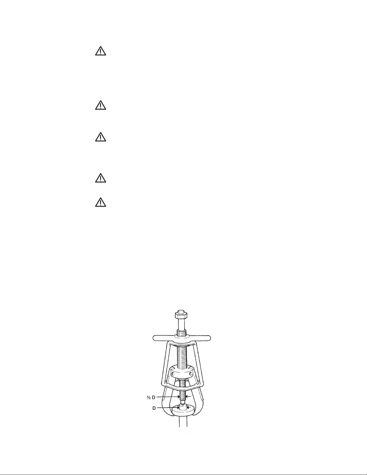
• The mechanical puller’s center bolt diameter must be at least one half
as large as the diameter of the shaft from which the object will be
removed. (See figure 2.)
Figure 2, Relative Size of Center Bolt versus Diameter of Shaft
(2)
• The maximum force exerted in tons should be 7 to 10 times the diameter of the shaft in
inches or 0.3 to 0.4 times the diameter in millimeters. (Example: A 1½” (40mm) diameter
shaft would generally require a 15 ton puller.)
• Long Jaws are available for larger capacity pullers. To change jaws, remove the ball lock
pins and slide the standard jaws out of the cage. Insert the “T” of the long jaws into the
T-slot of the cage and secure the jaws by inserting ball lock pins.
CAUTION
The rating of the puller remains the same when using the long jaws but the gripping
force is reduced by 75%. Never attempt to pry the puller by inserting anything
between the jaws. This may cause center bolt damage.
• Distortion of the jawhead assembly will occur if the bolt nut is continually forced against the
jawhead assembly. To reduce this risk, use the optional shaft protectors/ extenders that fit
over the puller’s end for tip protection and additional reach.
Note
It is impossible to predict the exact force needed for every pulling situation. The amount of press
fit and force of removal can vary greatly between jobs. The set-up requirements along with the
size, shape, and condition of the parts being pulled are variables which must be considered.
Study each pulling application before you select your puller. Notice that a significant amount of
force can be exerted with a puller. Respect these forces and always observe all safety precautions
and warnings.
OPERATION
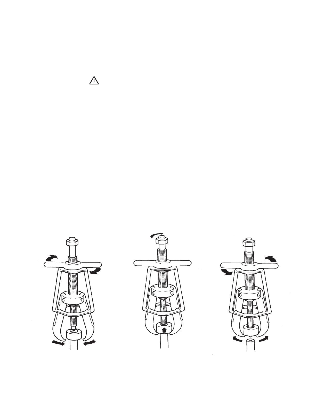
Figure 3
Figure 4
Figure 5
(3)
Mechanical Pullers
1. Make sure that all items being pulled are supported by a means other than the puller. Do not
use the puller for lifting or supporting objects.
2. Before each use, lubricate the center bolt threads with a graphite-based lubricant.
3. To operate puller, grasp the puller with one hand and turn the T-handle counter-clockwise
with the other hand until the jaw opening is big enough to fit over the component to be
pulled.
CAUTION
Do not pinch your fingers during this process.
4. Place puller over component to be pulled. When only the inner bearing race is remaining on
the shaft, clean the shaft first with emery cloth and then attach the jaws in the ball groove.
If the jaws appear to be coming out of the ball groove, loosen the center bolt and re-tighten
the T-Handle by hand. This may be necessary when the puller is new to get the jaws to
properly seat in the cage.
5. Turn the T-Handle clockwise to tighten the jaws firmly onto the component. (See Figure 3.)
6. Make sure that the center of the puller is aligned with the center of the shaft of the
component to be pulled. Using hand tools only, tighten the center bolt to pull the component
off of its shaft. (See Figure 4.)
To remove the component from the puller, turn the T-Handle counter-clockwise to open the
jaws. (See Figure 5.)
Maintenance
Always clean the puller after use and store in a clean, dry place.
Hydraulic Pullers
1. Make sure that all items being pulled are supported by a means other than the puller. Do not
use the puller for lifting or supporting objects.
2. Install cylinder into puller by threading collar threads clock-wise into the jawhead assembly.
Make sure that the cylinder collar threads are fully engaged in the puller. Attach lift plate
to the coupler-end of the cylinder. Remove the saddle from the cylinder and insert the ram
point into the plunger. Select the ram point that will provide maximum contact with the shaft
end.
3. To operate puller, grasp the puller with one hand and turn the T-handle counter-clockwise
with the other hand until the jaw opening is big enough to fit over the component to be
pulled.
CAUTION
Do not pinch your fingers during this process.
(4)
4. Place the puller over the component to be pulled. (See Figure 3.) When only the inner
bearing race is remaining on the shaft, clean the shaft first with emery cloth and then attach
the jaws in the ball groove.
If the jaws appear to be coming out of the ball groove, release hydraulic pressure and re-
tighten the T-Handle by hand. This may be necessary when the puller is new to get the jaws
to properly seat in the cage.
5. Turn the T-handle clockwise to tighten the jaws firmly onto the component.
6. Make sure that the puller is square with the component to be pulled. Advance the plunger
until the ram point contacts the shaft to ensure correct alignment. (If necessary, refer to the
pump’s instruction sheet.) The center of the ram point should be aligned with the center of
the shaft. Continue to advance the plunger slowly to pull the component off of the shaft. Do
not re-tighten the T-handle during the pulling operation. Never exceed the maximum torque
rating of the pullers.
Maintenance
Always clean the puller after use and store in a clean, dry place.
100-Ton Hydraulic Puller
WARNING
Do stand on, under, or near puller while in use. Keep hands, feet and clothing
away from moving parts.
WARNING
When transporting puller, always place the puller in its lowest position and
remove ram extenders.
1. Make sure that all items being pulled are supported by a means other than the puller. Do not
use the puller for lifting or supporting objects.
2. Align the puller to the shaft to ensure a straight pull. (The puller’s lift cart can raise the
puller up to 5 feet. For distances beyond 5 feet, the puller can be removed from the cart. See
Removing Puller from Lift Cart.)
To raise the puller, place the cylinder control valve in the “Hoist Oil Supply” position, open
the puller hoist vertical control valve, and raise the puller by placing the remote jog switch
in the “On” position.
When puller has reached the desired height, release the remote jog switch and close the
vertical control valve.
To lower the puller, place the cylinder control valve in the “Hoist Lower” position, turn the
hoist vertical control valve counterclockwise, and close the hoist vertical control valve after
the puller has reached its desired height.
Note
The restrictor valve, located at the top of the hoist cylinder, is used to control the rate of
puller descent. This valve should be set at the desired rate and locked in place using the nut
on the valve shaft. (An appropriate starting point is one full turn from the closed position
This restrictor valve is only a one-way restrictor valve; it does not affect the rate at which
the puller is raised.)
(5)

WARNING
Always keep the puller hoist vertical control valve closed when not adjusting the
vertical position.
3. Open the jaws to the desired spread.
Place the cylinder control valve lever in the “Oil Supply” position, place the cage control
valve lever in the “Jaw Open” position, and activate the pump by placing the remote jog
switch in the “On” position. Release the remote jog switch when the jaws have reached the
correct spread.
To close jaws, place the cylinder control valve in the oil supply position, place the cage
control valve lever in the “Jaw Control” position, and activate the pump by placing the
remote jog switch in the “On” position.
4. Adjust jaw tips so the jaws will pull on a flat surface.
1
Always use the maximum pulling surface of the jaw. Adjust the jaw tips by turning the 1
/
"
4
cap screw. To angle tip inward, turn the cap screw clockwise. To angle the tip outward, turn
the cap screw counterclockwise. Before pulling, always ensure that the machined caps are
properly fitted to the curved surface.
5. Extend the 100-ton cylinder.
Place the 100-ton cylinder control valve in the “Extend” position and activate the pump by
placing the remote jog switch in the “On” position.
To retract cylinder, place the 100-ton cylinder control valve in the “Retract” position. The
cylinder will retract automatically without activating the pump.
Removing Puller from Lift Cart
1. Support puller weight using the lifting brackets provided.
2. Close the puller hoist vertical control valve.
3. Disconnect the puller hoist hose coupler at the control panel.
1
4. Remove the (2)
/
" bolts that fasten the locking plate to the puller lift bracket.
2
5. Remove the puller from the cart by rotating the cart while keeping the puller stationary.
Maintenance
Keep slide rollers and mast clean and lubricated with light machine oil. Note that a
small amount of oil seepage from the breather vent on the hoist cylinder is normal.
(6)
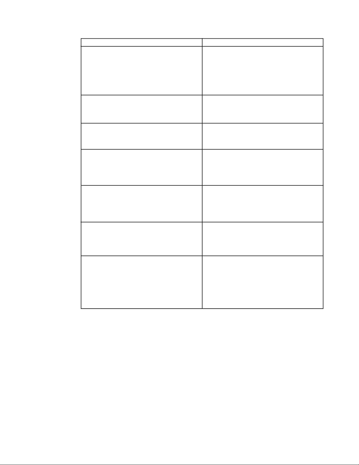
Troubleshooting
Problem
Possible Cause
1. Cylinder will not advance
A. Pump release valve open
B. No oil in pump
C. Air in hydraulic system
D. Couplers are not fully tightened
E. Blocked hydraulic line
2. Cylinder advances partly
A. Oil level in pump too low
B. Cylinder’s plunger binding
3. Cylinder advances in spurts
A. Air in hydraulic system
B. Cylinder’s plunger binding
4. Cylinder advances slower than
A. Leaking connection
normal
B. Restricted hydraulic line
C. Loose coupler or fitting
5. Cylinder advances but will not hold pressure
A. Seals leaking
B. Leaking connection
C. Pump malfunction
6. Cylinder leaks oil
A. Worn or damaged plunger
B. Leaking or loose connection
C. Internal leakage
7. Cylinder will not retract or retracts slower
A. Pump release closed
than normal
B. Coupler not fully closed
C. Blocked hydraulic line
D. Pump reservoir over-filled
E. Cylinder damaged
(7)
