Rotel RKB-250: Speakers
Speakers: Rotel RKB-250
13
English Input Level Controls
Two controls on the front panel, one for
each channel, provide input level adjust-
ments. These allow you to adjust the gain of
the amplifier to match other components in
the system. The L level control changes the
gain of the left channel; the R level control
changes the right channel.
To adjust these controls, use a small, flat-
blade screwdriver. Turn the control clock-
wise to increase gain. Turn counterclockwise
to reduce gain.
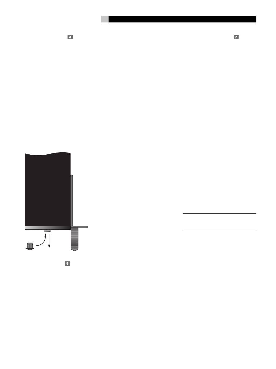
For easier adjustment, install the supplied vol-
ume control knobs by gently pressing them
onto the control shafts. Alternatively, you can
prevent inadvertant adjustment by installing
the supplied rubber plugs to conceal the vol-
ume controls.
Signal Output Link
This pair of RCA connections can be used to
pass the unprocessed input signals to anoth-
er audio component, for example to “daisy-
chain” an additional amplifier to drive a sec-
ond set of speakers. Any INPUT SIGNAL is
also available at these LINK outputs.
Speakers
The RKB-250 has two pair of speaker con-
nectors, one pair for each channel.
Speaker Selection
The nominal impedance of the loudspeaker(s)
connected to the RKB-250
should be a mini-
mum of 4 ohms. When driving multiple pairs
of speakers connected in parallel, the effec-
tive impedance the amplifier sees is cut in
half. For example, when driving two pair of
8 ohm speakers, the amplifier sees a 4 ohm
load. When driving multiple speakers in par-
allel, select speakers with a nominal imped-
ance of 8 ohms or higher.
Speaker Wire Selection
Use insulated two-conductor stranded wire
to connect the RKB-250 to the speakers.
The size and quality of the wire can have
an audible effect on the performance of the
system. Standard speaker wire will work,
but can result in lower output or diminished
bass response, particularly over longer dis-
tances. In general, heavier wire will improve
the sound. For best performance, you may
want to consider special high-quality speak-
er cables. Your authorized Rotel dealer can
help in the selection of appropriate cables
for your system.
Polarity and Phasing
The polarity or positive/negative orientation
of the connections for every speaker and am-
plifier connection must be consistent so all the
speakers will be in phase. If the polarity of
one connection is mistakenly reversed, bass
output will be very weak and stereo imaging
degraded. All speaker wire is marked so you
can identify the two conductors. There may
be ribs or a stripe on the insulation of one
conductor. The wire may have clear insula-
tion with different color conductors (copper
and silver). There may be polarity indica-
tions printed on the insulation. Identify the
positive and negative conductors and be
consistent with every speaker and amplifier
connection.
Speaker Connections
See Figure 2
The RKB-250 has one pair of color coded
connections per channel. Labels above the
connectors show the proper connections.
These speaker connectors accept bare wire,
connector lugs, or “banana” type connectors
(except in the European Community countries
where their use is not permitted).
Route the wires from the RKB-250 to the speak-
ers. Give yourself enough slack so you can
move the components enough to allow ac-
cess to the speaker connectors
.
If you are using banana plugs, connect them
to the wires and then plug into the backs of
the speaker connectors
.
The collars of the
speaker connectors should be screwed in
all the way (clockwise).
If you are using terminal lugs, connect them to
the wires. If you are attaching bare wires di-
rectly to the speaker connectors, separate the
wire conductors and strip back the insulation
from the end of each conductor. Be careful
not to cut into the wire strands. Unscrew (turn
counterclockwise) the speaker connector col-
lar. Place the connector lug around the shaft,
or insert the bundled wire into the hole in the
shaft. Turn the collars clockwise to clamp the
connector lug or wire firmly in place.
NOTE
:
Be sure there are no loose wire strands
that could touch adjacent wires or connec-
tors.
Connect the left speaker to the pair of speaker
connectors labeled LEFT. Connect the right
speaker to the speaker connectors labeled
RIGHT. Follow the labels printed above the
connectors, Make sure that the positive ter-
minal of the speaker is connected to the +
terminal on the amplifier. Make sure that the
negative terminal of the speaker is connected
to the – terminal of the amplifier.
Оглавление
- About Rotel
- Signal Connections
- Speakers
- Specifications
- Au sujet de Rotel
- Pour démarrer
- Alimentation secteur et mise sous tension
- Branchements des signaux en entrée
- Enceintes acoustiques
- Problèmes de fonctionnement
- Acerca de Rotel
- Para Empezar
- Alimentación y Control
- Conexiones de Señal
- Cajas Acústicas
- Problemas y Posibles Soluciones
- Alcune Parole Sulla Rotel
- Per Cominciare
- Alimentazione e comandi
- Collegamenti di segnale
- Diffusori
- Caratteristiche tecniche
- Die Firma Rotel
- Netzspannung und Bedienung
- Signalanschlüsse
- Störungssuche
- Wij van Rotel
- Aan de slag met de RKB-250
- Het aansluiten op het lichtnet en de bediening
- De ingangen
- Wat te doen bij problemen
- Technische gegevens
- Om Rotel
- Ström och strömfunktioner
- Högtalare
- Felsökning
- О компании ROTEL
- Ввод в эксплуатацию
- Подключение сети переменного тока и управление питанием
- Разъемы для сигналов
- Громкоговорители
- Характеристики
