Benelli M3 Convertible Semi-Auto Pump Shotgun – страница 6
Инструкция к Benelli M3 Convertible Semi-Auto Pump Shotgun
100
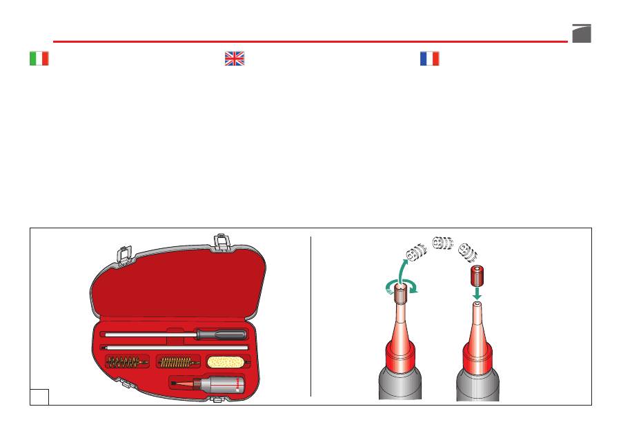
4) per la buona conservazione dell'arma, si
consiglia di tenere lubrificate
le parti sog-
gette
agli agenti atmosferici.
NOTA:
per la pulizia dello strozzatore e del-
la relativa sede leggere attentamente il para-
grafo “Strozzatore interno” pag. 156.
Utilizzare sempre il set di pulizia
(non in
dotazione con il fucile)
e l'olio Benelli Armi
(fig. 36).
4) to keep the gun in good order, oiling of
the
parts subject
to atmospheric corro-
sion is recommended.
NOTE:
for maintenance of the choke and
relative seat, carefully read the instructions
in the “Internal choke” paragraph, page 156.
Use only Benelli Armi cleaning set
(not
equipped with shotgun)
and oil
(fig. 36).
4) pour la bonne conservation de l’arme,
n’oubliez pas de veiller à ce que
les par-
ties pouvant être agressées
par les agents
atmosphériques soient toujours lubrifiées.
NOTA:
avant de nettoyer le choke et son siè-
ge, lire attentivement le paragraphe “Choke
intérieur” en p. 156.
Utiliser toujours le set de nettoyage
(qui n’est
pas fourni en dotation avec le fusil)
et l’huile
Benelli Armi
(fig. 36).
36
101
4) um das Gewehr immer in gutem Zustand
zu halten, wird empfohlen die der Witte-
rung
ausgesetzten Teile
stets gut gesch-
miert zu halten.
HINWEIS:
Zur Choke-Reinigung und seines
Sitzes aufmerksam den Paragraphen “Innen-
Choke” Seite 157 lesen.
Immer das Reinigungsset verwenden
(nicht
im Lieferumfang des Gewehrs enthalten)
sowie Öl von
Benelli Armi
(Abb. 36).
4) para una buena conservación del arma se
aconseja mantener lubricadas las
partes
sujetas
a los agentes atmosféricos.
NOTA:
para la limpieza del choke y de su
alojamiento lea cuidadosamente el punto
“Choke interno” pág. 157.
Utilice siempre el juego de limpieza
(no for-
ma parte de la dotación del fusil)
y el aceite
Benelli Armi
(fig. 36).
4) для лучшей сохранности оружия
рекомендуется держать смазанными
части, подверженные
воздействию
атмосферы.
ПРИМЕЧАНИЕ:
для очистки сменного чока и
его места посадки внимательно прочитать
раздел “Сменные чоки”, стр. 157.
Для чистки ружья используйте только
оригинальный набор принадлежностей
(не
включён в стандартную комплектацию)
и
масло Бенелли
(рис. 36).

102
Smontaggio dell’arma
(per manutenzione e pulizia)
Prima di effettuare qualunque tipo di inter-
vento sul fucile, accertatevi sempre che
camera di scoppio, elevatore e serbatoio sia-
no completamente vuoti!
(Leggere attenta-
mente le istruzioni di caricamento e scarica-
mento dell'arma).
Procedura di smontaggio
1) Portare
l'anello commutatore funzio-
namento
, montato sulla parte anteriore
dell'asta di armamento, nella condizione
di funzionamento manuale - a pompa
(vedi paragrafo “Commutazione funzio-
namento”).
2) Smontare l'anello unione canna-tubo ser-
batoio svitando la vite di fissaggio (fig.
15) e sfilandolo poi dalla sede sul tubo
serbatoio stesso (fig. 14).
3) Svitare completamente
il cappellotto
fis-
saggio canna e sfilarlo dal tubo serbatoio
(fig. 11).
4) Sfilare l'anello portabretelle dal tubo ser-
batoio.
Shotgun stripping
(for cleaning and maintenance)
Before starting any operation on your shot-
gun, make sure that the chamber and the
magazine are unloaded!
(Carefully read the
instructions on gun loading and unloading).
Stripping procedure
1) Switch
the selection ring
on the front of the
fore-end lever to manual (pump action).
(See the section “Action selection”).
2) Slacken the screw and remove the barrel-
magazine tube retaining ring (fig. 15)
from its seat on the magazine tube (fig.
14).
3) Remove the barrel
cap
from the maga-
zine (fig. 11).
4) Slide the sling swivel off the magazine
tube.
Démontage de l’arme
(pour le nettoyage et l’entretien)
Avant d’effectuer n’importe quelle interven-
tion sur votre fusil, assurez-vous toujours
que la chambre d’explosion et le magasin
sont complètement vides!
(Lire attentivement
les instructions de chargement et de déchar-
gement).
Marche à suivre pour le démontage
1) Amener
la bague de commutation de
fonctionnement
sur la partie avant du
levier d'armement, dans la condition de
fonctionnement manuel par pompe (voir
paragraphe "Commutation de fonctionne-
ment").
2) Démonter l’anneau de fixation canon-
tube magasin en dévissant la vis de fixa-
tion (fig. 15) et l’extraire de son logement
sur le tube magasin (fig. 14).
3) Dévisser complètement
le capuchon
de
fixation du canon et l'extraire du tube
magasin (fig. 11).
4) Extraire la bague porte-bretelles du tube
magasin.

103
Zerlegen der Waffe
(für die Reinigung und Wartung)
Vor jeder Waffenhandhabung sollten Sie
sicherstellen, dass die Patronenlager und das
Magazin völlig leer sind!
(Bitte lesen Sie auf-
merksam die Anweisungen für das Laden und
das Entladen der Waffe).
Zerlegen
1) Den
Selektionsring
vorne am Vordergriff
auf manuell schalten (Pumpbetrieb). (Be-
achten Sie den Abschnitt über die Funk-
tionswahl).
2) Lösen Sie den Montagering Lauf-Magazin-
rohr, indem sie die Schraube abschrauben
(Abb. 15) und schieben Sie ihn aus dem
Sitz auf dem Magazinrohr (Abb. 14).
3) Schrauben Sie die
Laufbefestigungskappe
los und entfernen Sie sie vom Magazin-
rohr (Abb. 11).
4) Schieben Sie den Riemenbügelring vom
Magazinrohr.
Desmontaje del arma
(para manutención y limpieza)
Antes de realizar cualquier tipo de opera-
ción en su fusil, compruebe siempre que la
cámara de explosión, el elevador y el
almacén estén completamente vacíos.
(Lea
atentamente las instrucciones para la carga y
la descarga del arma).
Procedimiento de desmontaje
1) Poner el
anillo conmutador de funciona-
miento
, montado en la parte anterior de
la varilla de armamento, en la posición
de funcionamiento manual - de bomba
(véase punto “Conmutación funciona-
miento”).
2) Desmonte el anillo de unión cañón-tubo
almacén destornillando el tornillo de fija-
ción (fig. 15) y quitándolo de su aloja-
miento en el mismo tubo almacén (fig.
14).
3) Destornille completamente
el capuchón
de fijación del cañón y quítelo del tubo
almacén (fig. 11).
4) Extraer el anillo porta-bandoleras del
tubo almacén.
Разборка оружия
(для обслуживания и чистки)
Перед тем, как выполнять любые операции
с Вашим ружьем, убедитесь, что патронник,
механизм подачи и магазин совершенно
пустые!
(внимательно прочитайте инструкции
по заряжанию и разряжанию оружия).
Порядок разборки
1) Установить
кольцо переключения
режима
функционирования,
расположенное на передней части цевья
в положение ручного (помпового) режима
(смотрите раздел “Переключение
режима”).
2) Демонтировать стопорное кольцо ствола-
трубки магазина, отвинтив крепежный
винт (рис. 15) и вынув из гнезда на трубке
самого магазина (рис. 14).
3) Полностью отвернуть
втулку
крепления
ствола и снять ее с трубки магазина (рис.
11).
4) Снять кольцо антабки с трубки магазина.
104
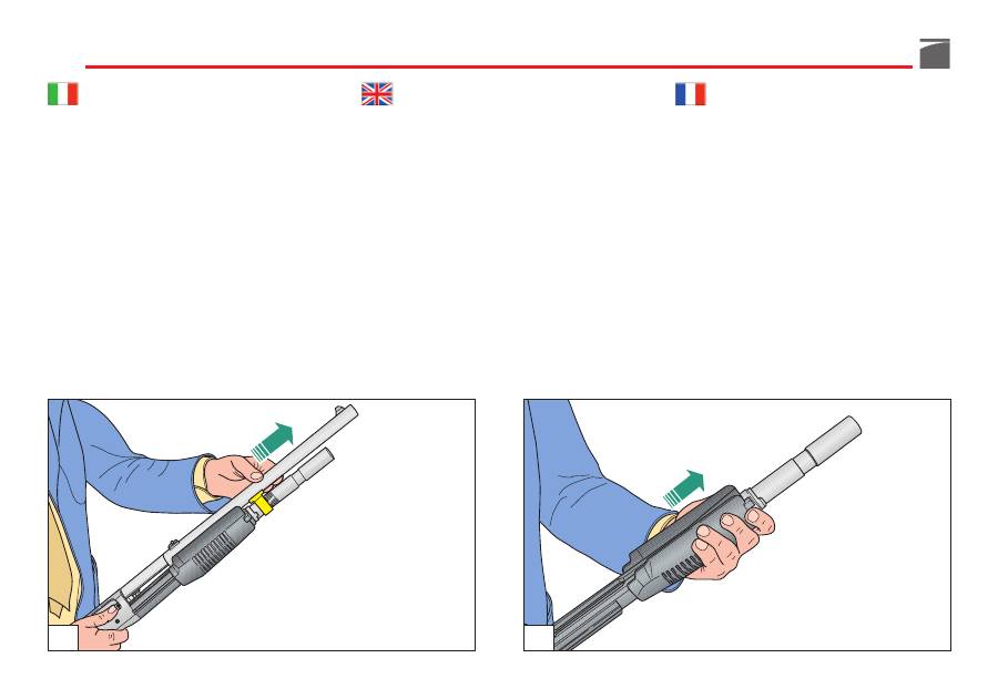
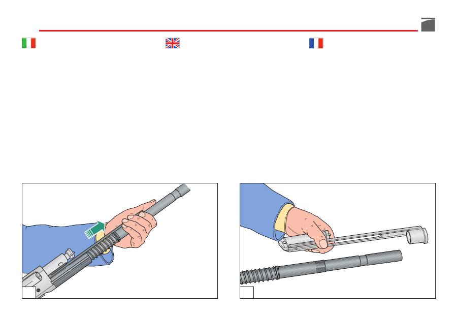
5) Impugnare il fucile con una mano e, con
l'altra, tirare in avanti
la canna
facendo
scorrere l'anello guida canna sul tubo
serbatoio (fig. 37) fino a smontaggio com-
pleto.
6) Separare
il gruppo commutatore-asta
armamento
dal gruppo bretelle-otturatore
mantenendo ruotato, con il pollice della
mano che impugna l'asta d'armamento
stessa, l'anello commutatore in senso ora-
rio e sfilando tutto il gruppo stesso dal
tubo serbatoio (fig. 38).
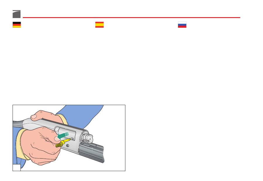
7) Togliere
la manetta d'armamento
con
uno strappo deciso (fig. 39).
5
)
Take the shotgun with the hand and pull
the barrel
forward sliding the barrel ring
along the magazine (fig. 37) until it comes
off.
6) Separate the
selection ring-fore-end lever
unit
from the bolt-swivel unit by keeping
the selection ring twisted clockwise with
the thumb of the hand holding the fore-
end lever and pulling the unit off the
tubular magazine (fig. 38).
7) Pull the
bolt handle
off with a firm tug
(fig. 39).
5) Saisir d’une main le fusil et de l’autre main
tirer
le canon
vers l'avant en faisant cou-
lisser la bague de guidage du canon sur le
tube magasin (fig. 37) jusqu'au démontage
complet.
6) Séparer
le groupe commutateur-levier
d'armement
du groupe bras de comman-
de et du pouce de la main qui tient le le-
vier d'armement, garder la bague du com-
mutateur tournée dans le sens des aiguil-
les d'une montre en extrayant tout le grou-
pe du tube magasin (fig. 38).
7) Dégager la
manette d’armement
avec un
coup net (fig. 39).
37
38
105
5) Halten Sie die Waffe mit einer Hand und
ziehen Sie, indem Sie den Führungsring
des Laufes
am Magazinrohr entlang schie-
ben, den Lauf nach vorne, bis (Abb. 37) er
abgeht.
6) Trennen Sie die
Einheit Selektionsring-
Vordergriff
von der Verschlussblockhalte-
rung, indem Sie mit dem Daumen den
Vordergriff halten, den Selektionsring in
Uhrzeigerrichtung drehen und den Auf-
bau vom Rohrmagazin abziehen (Abb.
38).
7) Den
Spannhebel
mit einer kräftigen Bewe-
gung herausziehen (Abb. 39).
5) Empuñar el fusil con una mano y, con a
otra, tirar hacia delante
el cañón
hacien-
do deslizar el anillo guía cañón en el
tubo almacén (fig. 37) hasta el desmon-
taje completo.
6) Separar
el grupo conmutador-varilla
armamento
del grupo bandoleras obtura-
dor manteniendo girado, con el pulgar de
la mano que empuña la misma varilla de
armamento, girar el anillo conmutador
en el sentido de las agujas de reloj y ex-
traer todo el grupo del tubo almacén (fig.
38).
7) Quite la
maneta de armado
de un solo
jalón (fig. 39).
5) Ухватить ружье одной рукой, а другой
потянуть вперед ствол, протягивая
направляющее кольцо ствола по трубке
магазина (рис. 37) до его полного снятия.
6) Отсоединить
узел переключатель-
цевье
от узла крепления затвора,
удерживая при помощи большого пальца
руки, которая лежит на цевье, в
повернутом положении по часовой
стрелке кольцо переключателя, после
чего снять весь узел целиком с трубки
магазина (рис. 38).
7) Резким рывком извлеките
рукоятку
затвора
(рис. 39).
39
106
8) Estrarre il gruppo bretelle-otturatore dal-
la carcassa facendolo scorrere in avanti
sul tubo serbatoio (fig. 40) ed avendo
cura di trattenere con la mano il gruppo
otturatore una volta fuori dalle guide
della carcassa (fig. 41) per evitare che
separandosi dalle bretelle cada a terra.
9) Separare
il gruppo bretelle
dal gruppo
otturatore (fig. 42).
10) Sfilare
il perno arresto percussore
dal
gruppo otturatore, avendo cura
di trat-
tenere
il percussore (fig. 43) che, diver-
samente, spinto dalla sua molla di ri-
chiamo, cadrebbe a terra.
8) Remove the bolt-swivel unit from the
receiver and slide it off the tubular
magazine (fig. 40), being careful not to
drop the bolt unit once it is out of its
guides (fig. 41) and separated from the
swivel.
9) Separate
the swivel
from the bolt unit
(fig. 42).
10) Pull
the firing pin retaining pin
out of
the bolt unit, being careful not to let the
unretained
firing pin be pushed out of
the bolt by its spring (fig. 43).
8) Extraire le groupe bras de commande
obturateur de la carcasse en le faisant
coulisser vers l'avant sur le tube maga-
sin (fig. 40) et en ayant soin de retenir
de la main le groupe obturateur lors-
qu'il est sorti des guides de la carcasse
(fig. 41) pour éviter qu'il ne s'éjecte par
terre lorsqu'il se sépare des bras.
9) Séparer
le groupe bras
du groupe obtu-
rateur (fig. 42).
10) Retenir
le pivot d'arrêt du percuteur
du
groupe obturateur en ayant soin
de re-
tenir
le percuteur (fig. 43) qui sans cela,
poussé par son ressort de rappel, s'éjec-
terait par terre.
40
41

107
8) Die Riemen- Verschlussblockeinheit aus
dem Gehäuse herausnehmen, indem Sie
sie aus dem Rohrmagazin schieben
(Abb. 40). Achten Sie darauf, dass Sie die
Verschlussblockeinheit nicht herunterfal-
len lassen, sobald sie aus der Führungs-
schiene des Gehäuses (Abb. 41) heraus-
getrennt ist.
9) Die Verschlussblockeinheit von der
Rie-
meneinheit
abtrennen (Abb. 42).
10) Ziehen Sie den
Schlagbolzenfixierstift
aus der Verschlussblockeinheit heraus,
dabei müssen Sie darauf
achten
, dass
der lockere Schlagbolzen nicht durch
seine Bolzenfeder herausgeschleudert
wird (Abb. 43).
8) Extraer el grupo bandoleras-obturador
de la carcasa haciéndolo deslizar hacia
delante en el tubo almacén (fig. 40) y
con esmero de retener con la mano el
grupo obturador después de haberlo
extraído de las guías de la carcasa (fig.
41) para evitar que al separarse las ban-
doleras se caiga al suelo.
9) Separar
el grupo bandoleras
del grupo
obturador (fig. 42).
10) Extraer
el perno de parada percutor
del
grupo obturador, con el esmero de rete-
ner el percutor (fig. 43) que, al contra-
rio, empujado por su resorte antagonis-
ta, se caería al suelo.
8)
Извлеките узел крепления затвора из
ствольной коробки, протягивая его
вперед вдоль трубки магазина (рис. 40);
действовать аккуратно, не забывая
удерживать одной рукой узел затвора
после его выхода с направляющих
затворной коробки (рис. 41). В
противном случае узел затвора может
упасть.
9)
Снять
узел крепления затвора
с
самого узла затвора (рис. 42).
10)
Снять
стопорную шпильку бойка
с
узла затвора; необходимо
тщательно
удерживать
боек (рис. 43), поскольку в
противном случае под воздействием
возвратной пружины он может упасть.
42
43
108
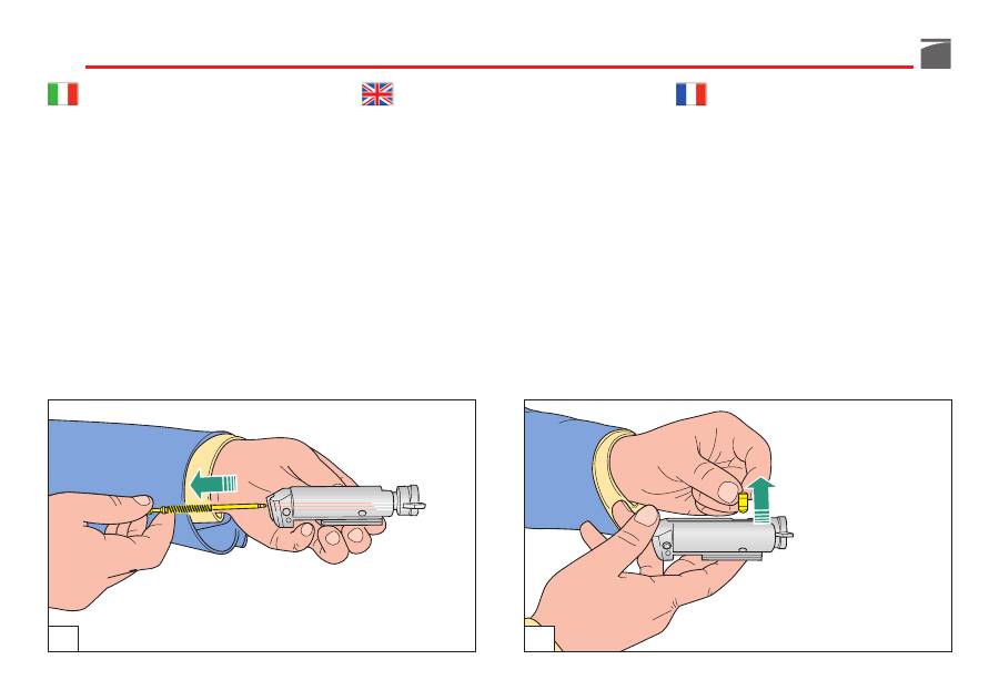
11) Estrarre dall'otturatore il percussore
con
la sua molla
di richiamo (fig. 44).
12) Togliere
il perno
rotazione testa di chiu-
sura sfilandolo dalla sua sede (fig. 45).
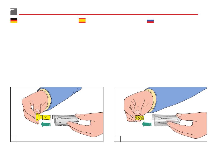
13) Sfilare
la testa di chiusura
dall'otturato-
re (fig. 46).
14) Togliere
la molla di rinculo
otturatore
dalla sua sede (fig. 47).
11) Remove the firing pin and firing pin
spring
from the bolt (fig. 44).
12) Remove the locking head
pin
from the
bolt (fig. 45).
13) Remove the
bolt locking head
from the
bolt (fig. 46).
14) Remove the
inertia spring
from its seat
in the bolt (fig. 47).
11) Extraire de l’obturateur le percuteur
avec
son ressort
de rappel (fig. 44).
12) Retirer
le pivot
de rotation de la tête de
fermeture en le dégageant de son siège
(fig. 45).
13) Extraire
la tête de fermeture
de l’obtu-
rateur (fig. 46).
14) Retirer de son siège
le ressort de recul
de l'obturateur (fig. 47).
44
45
109
11)
Den Schlagbolzen mit der Spannfeder
aus dem Verschlussblock herausziehen
(Abb. 44).
12) Den
Drehzapfen
des Verschlusskopfes
aus seinem Sitz herausziehen (Abb. 45).
13) Den
Verschlusskopf
aus dem Verschluss
herausziehen (Abb. 46).
14) Die
Inertial-Feder
des Verschlusses aus
ihrem Sitz herausnehmen (Abb. 47).
11) Extraiga del obturador el percutor y
su
resorte
antagonista (fig. 44).
12) Quite
el eje
de rotación de la cabeza de
cierre sacándolo de su alojamiento (fig.
45).
13) Quite
la cabeza de cierre
del obturador
(fig. 46).
14) Quite
el resorte de retroceso
del obtu-
rador de su alojamiento (fig. 47).
11) Извлеките боек из затвора вместе
с его
пружиной
(рис. 44).
12) Снимите
шпильку
фиксации личинки
затвора, вынув ее из гнезда (рис. 45).
13) Извлеките
личинку затвора
(рис. 46).
14) Удалите
инерционную пружину
затвора из гнезда (рис. 47).
46
47
110
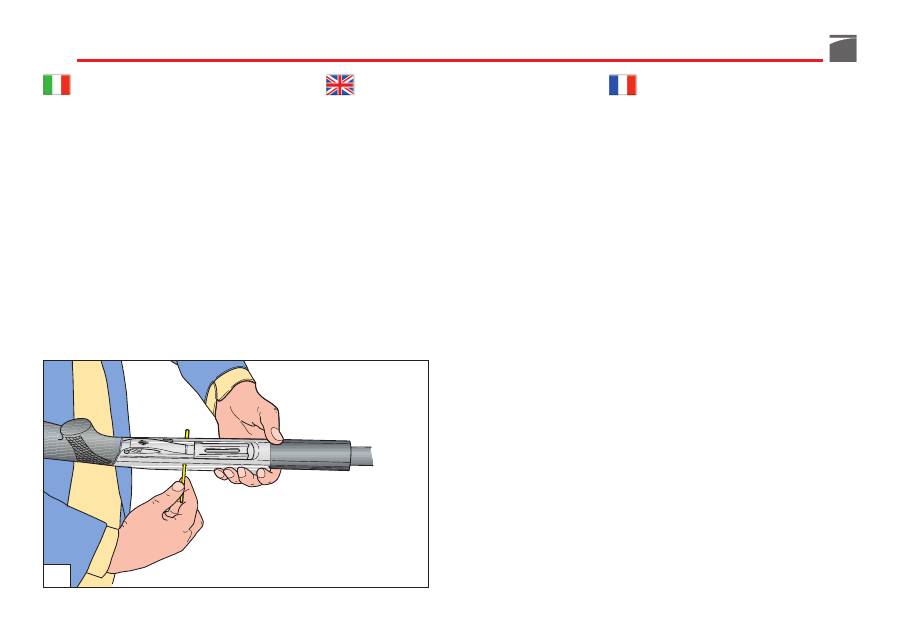
15) Sfilare dal gruppo calcio-carcassa
la spi-
na arresto guardia,
spingendola da
destra o da sinistra con la punta del per-
cussore stesso o con un punteruolo qua-
lunque (fig. 48).
16)
Premere
il bottone comando elevatore
e
sfilare
in avanti il gruppo guardia (fig.
49).
Il fucile è completamente smontato; le parti
che possono interessare per una accurata ve-
rifica e pulizia sono tutte separate.
15) Extract the
trigger group stop plug
from
the stock-receiver unit, thrusting it from
right or left with the point of the same
firing pin or punch (fig. 48).
16)
Press
the carrier release button and
ex-
tract
the trigger guard unit towards the
front (fig. 49).
The shotgun is now completely stripped. All
the parts that require routine maintenance and
cleaning are disassembled.
15) Retirer du groupe crosse-carcasse
la
goupille d’arrêt de la sous-garde
en la
poussant de la droite ou de la gauche
avec la pointe du percuteur même ou
avec un pointeau quelconque (fig. 48).
16)
Appuyer
sur le bouton de commande
élévateur et
dégager
vers l’avant le grou-
pe sous-garde (fig. 49).
Le fusil est complètement démonté: les par-
ties qui doivent être vérifiées et nettoyées
sont toutes démontées.
48

111
15) Aus der Gruppe Schaft - Gehäuse den
Arretierstift der Abzugseinheit
von der
rechten oder der linken Seite her entfer-
nen. Zum Heraustreiben den Kopf des
Schlagbolzens oder einen geeigneten
Stift benutzen (Abb. 48).
16) Den Verschlussfangknopf
drücken
und
die komplette Abzugsgruppe nach vorn
entnehmen
(Abb. 49).
Das Gewehr ist nun komplett zerlegt. Die Tei-
le, die einer Wartung oder einer Reinigung
bedürfen liegen nun separat bereit.
15) Quite del grupo culata-carcasa
la espiga
de parada del guardamonte
, empuján-
dola desde la derecha o la izquierda
con la punta del mismo percutor o con
un punzón (fig. 48).
16)
Pulse
el botón de mando del elevador y
deslice
hacia adelante el grupo guarda-
monte (fig. 49).
El fusil está completamente desmontado; las
partes que pueden interesar para una verifica-
ción cuidadosa y para la limpieza están sepa-
radas.
15) Выньте из ствольной коробки
шпильку
фиксации
ударно-спускового
механизма,
толкая ее слева или справа
выколоткой (рис. 48).
16)
Нажмите
на кнопку фиксатора
подавателя патронов и
снимите
, толкая
вперед, ударно-спусковой механизм (рис.
49).
Ружье полностью разобрано. Детали, которые
следует проверить и очистить, разобраны.
49
112
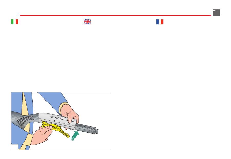
Montaggio dell’arma
Per un corretto montaggio dell'arma, proce-
dere nel seguente ordine:
1) Impugnare il gruppo calcio-carcassa e,
premere
il bottone comando elevatore,
inserendo contemporaneamente
il grup-
po guardia
completo,
a cane armato
,
nella carcassa in posizione leggermente
avanzata rispetto alla posizione finale di
montaggio (fig. 50); arretrare poi legger-
mente tutto il gruppo guardia
fino a por-
tarlo in battuta
sulla parte posteriore del-
la carcassa stessa, avendo cura che il pia-
no inferiore della guardia collimi con il
piano inferiore della carcassa (fig. 51).
Shotgun assembly
For correct assembly after cleaning and main-
tenance operations, proceed as follows:
1) Grip the stock-receiver group:
press
the
carrier button so that the whole protec-
tion cover unit is simultaneously fitted
into the receiver
(hammer must be cock-
ed)
and is kept in a slightly advanced
position compared to its final position
(fig. 50). Slightly withdraw the whole pro-
tection cover until it is
wedged
against
the back end of the receiver, taking care
that the bottom part of the protection
cover coincides with the bottom part of
the receiver (fig. 51).
Remontage de l’arme
Pour remonter l’arme correctement suivre la
marche ci-dessous:
1) Saisir le groupe crosse-carcasse et
ap-
puyer
sur le bouton de commande éléva-
teur, en introduisant en même temps
le
groupe sous-garde
complet -
chien armé
dans la carcasse en position légèrement
avancée par rapport à la position finale
de montage (fig. 50). Faire reculer légère-
ment tout le groupe de la sous-garde
jusqu'à le faire buter
sur la partie arrière
de la carcasse même en veillant à ce que
le plan inférieur de la sous-garde se trou-
ve exactement au même niveau que le
plan inférieur de la carcasse (fig. 51).
50

113
Zusammenbauen der Waffe
Die Waffe wird auf folgende Weise korrekt
zusammengebaut:
1) Die Gruppe Hinterschaft mit Gehäuse
umfassen, den Verschlussfangknopf
drücken
und dabei gleichzeitig die kom-
plette
Abzugsgruppe, mit gespanntem
Schlagstück
, in das Gehäuse einsetzen,
die Position sollte etwas weiter vorne sein
als die definitive Montagestellung, dann
die gesamte Abzugsgruppe leicht nach
hinten
bis zum Anschlag
an den hinteren
Teil des Gehäuses selbst verschieben
(Abb. 50). Schieben Sie die Abzugsgruppe
leicht zurück und stellen Sie sicher, dass
die untere Fläche mit der des Gehäuses
übereinstimmt (Abb. 51).
Montaje del arma
Para el correcto montaje del arma proceda
en el siguiente orden:
1) Coja el grupo culata-carcasa y
pulse
el
botón de mando del elevador introdu-
ciendo al mismo tiempo el
grupo guarda-
monte
completo, con el
martillo armado
,
en la carcasa, en posición ligeramente
avanzada respecto a la posición final del
montaje (fig. 50); haga retroceder un poco
todo el grupo guardamonte
hasta que
tope
en la parte posterior de la misma
carcasa cuidando que el plano inferior del
guardamonte coincida con el plano infe-
rior de la carcasa (fig. 51).
Сборка ружья
Для правильной сборки ружья действуйте в
указанной последовательности:
1) Возьмите в руку узел приклад - ствольная
коробка и
нажмите
на кнопку фиксатора
подавателя; одновременно вставляйте
укомплектованный
ударно-спусковой
механизм со взведенным курком
в
ствольную коробку в слегка продвинутом
вперед положении, затем слегка отведите
назад (рис. 50) ударно-спусковой
механизм
до его фиксации
в ствольной
коробке, обращая внимание на то, чтобы
нижняя поверхность корпуса ударно-
спускового механизма совпадала с
нижней поверхностью ствольной коробки
(рис. 51).
51

114
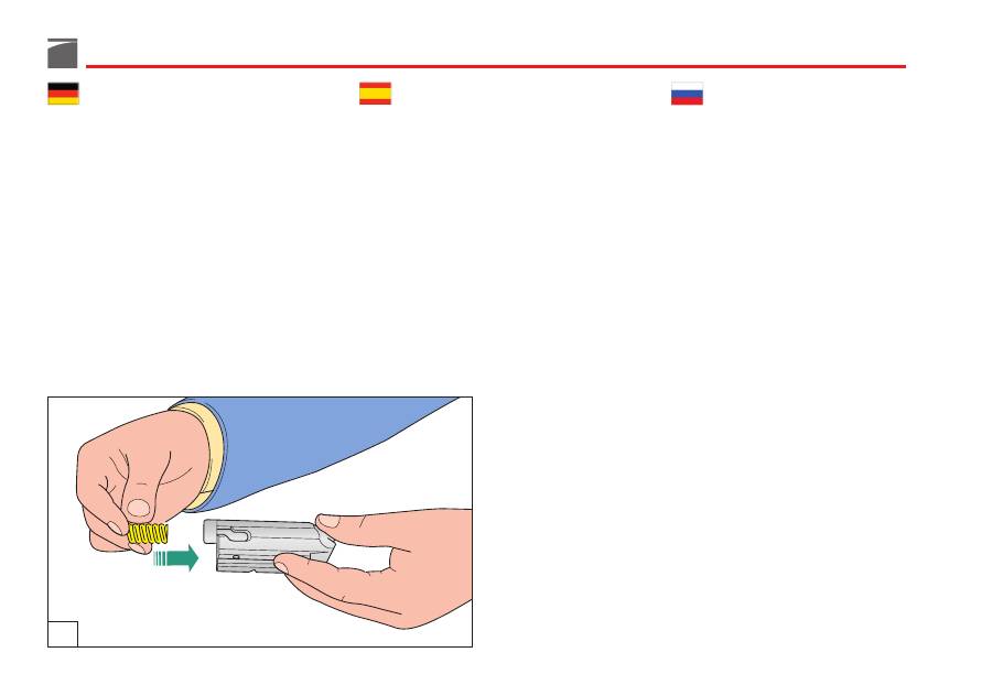
2) Infilare da destra o da sinistra
la spina
arresto guardia fermandola quando si tro-
va completamente inserita nella carcassa
(fig. 52).
3) Infilare
la molla
rinculo otturatore nella
propria sede (fig. 53).
ATTENZIONE:
accertarsi di collocare
sempre
la molla di rinculo dell'otturatore
tra testa di
chiusura ed otturatore stesso
, per evitare che
- nella fase di chiusura -
possa partire il col-
po
.
2) Push the trigger guard
pin
bush into the
receiver from the right or left, until it is
completely inside (fig. 52).
3) Slide the bolt recoil
spring
into its appro-
priate position (fig. 53).
NOTE:
always
make sure that the bolt recoil
spring is positioned
between the locking
head and the bolt itself
, in order to avoid
a
shot being fired
when the bolt is closed.
2) Introduire, par la droite ou par la gauche,
la
goupille
d’arrêt de la sous-garde et ne
s’arrêter que lorsqu’elle aura été entière-
ment introduite sur la carcasse (fig. 52).
3) Introduire
le ressort
de recul de l'obtura-
teur dans son logement (fig. 53).
ATTENTION:
s’assurer que le ressort de recul
de l’obturateur est
toujours
placé
entre la
tête de fermeture et l’obturateur
pour éviter
le risque
qu’un coup puisse partir
par mégar-
de durant la fermeture.
52
115
2) Den
Befestigungsstift
des Abzugs von
rechts oder links einschieben und fixieren,
nachdem er vollständig in das Gehäuse
eingesteckt wurde (Abb. 52).
3) Die
Inertial-Feder
des Verschlusses in
ihren Sitz einführen (Abb. 53).
ACHTUNG:
stets
prüfen, ob die Inertialfeder
auch zwischen dem
Verschlusskopf und dem
Verschlussblock
eingesetzt wurde, um beim
Verriegeln eine
ungewollte Schussabgabe
zu
vermeiden!
2) Introduzca desde la derecha o la izquier-
da
la espiga
de parada del guardamonte
fijándola cuando se encuentre completa-
mente introducida en la carcasa (fig. 52).
3) Introduzca
el resorte
de retroceso del
obturador en su alojamiento (fig. 53).
ATENCIÓN:
asegúrese
siempre
de colocar el
resorte de retroceso del obturador
entre la
cabeza de cierre y el obturador mismo
, para
evitar que en fase de cierre
pueda partir un
tiro.
2) Вставьте справа или слева
шпильку
фиксации
ударно-спускового механизма
(рис. 52).
3) Установите инерционную
пружину
в
собственное гнездо (рис. 53).
ВНИМАНИЕ:
убедитесь в том, что
инерционная пружина затвора
находится
между личинкой затвора и самим затвором,
для того, чтобы избежать
случайного
выстрела
во время закрытия затвора.
53
116
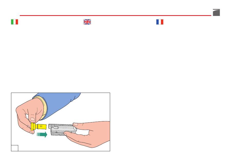
4) Prendere
la testa di chiusura
ed infilarla
nell’otturatore avendo cura che
il foro
sul
suo gambo collimi con
l’asola
dell’ottura-
tore stesso (fig. 54).
AVVERTENZA:
i piani inclinati ricavati sul
gambo della testa di chiusura
non devono
essere visibili a pezzo montato.
5) Infilare
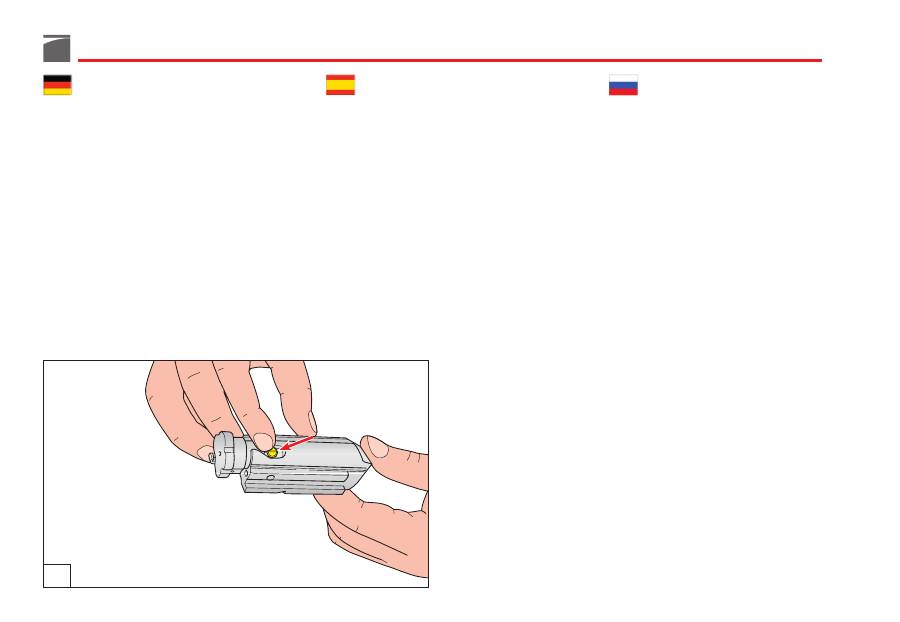
il perno
rotazione testa di chiu-
sura nel foro ricavato sul gambo della
testa di chiusura, facendolo passare attra-
verso l’asola dell’otturatore (fig. 55).
4) Slide the
locking head
into the bolt, mak-
ing sure that the
hole
on its stem coin-
cides with the
slot
on the bolt (fig. 54).
WARNING:
the slanted surfaces on the lock-
ing head’s stem should
not be visible
once
the bolt locking head is mounted.
5) Insert the locking head
pin
in its hole on
the locking head’s stem, through the slot
on the bolt (fig. 55).
4) Introduire
la tête de fermeture
dans l’ob-
turateur, en faisant coïncider
le trou
avec
son devant avec
la boutonnière
de l’ob-
turateur (fig. 54).
ATTENTION:
les plans inclinés obtenus sur le
devant de la tête de fermeture
ne doivent pas
être visibles lorsque la pièce est montée.
5) Engager
l’axe
de rotation de la tête de fer-
meture dans son logement sur la tête, en
le faisant passer à travers la boutonnière
de l’obturateur (fig. 55).
54
117
4) Den
Verschlusskopf
in den Verschluss-
block einschieben und darauf achten,
dass die
Bohrung
am Stamm des Versch-
lusskopfes mit der entsprechenden
Aus-
fräsung
des Verschlussblockes überein-
stimmt (Abb. 54).
VORSICHT:
Die geneigten Ebenen am Stamm
des Verschlussblocks
dürfen
nach der Monta-
ge
nicht sichtbar sein.
5) Den
Drehzapfen
des Verschlusskopfes
durch die Ausfräsung im Verschlussblock
in die vorgesehene Bohrung im Stamm
des Verschlusskopfes stecken (Abb. 55).
4) Coja
la cabeza de cierre
e introdúzcala
en el obturador, cuidando que el
agujero
que lleva en el vástago coincida con el
ojal
del obturador mismo (fig. 54).
ADVERTENCIA:
los planos inclinados que se
encuentran en el vástago de la cabeza de
cierre
no se deben
ver cuando la pieza está
montada.
5) Introduzca
el eje
de rotación de la cabe-
za de cierre en el agujero de alojamiento
que se encuentra en el vástago de la
misma, pasándolo por el ojal del obtura-
dor (fig. 55).
4) Установите
личинку
в тело затвора так,
чтобы
отверстие
на ее стебле совпадало
с
прорезью
самого затвора (рис. 54).
ПРЕДУПРЕЖДЕНИЕ:
наклонные поверхности
на стебле личинки,
не должны быть
видны
после ее установки в тело затвора.
5) Вставьте
шпильку
фиксации личинки
затвора в отверстие, имеющееся в стебле,
пропустив ее через прорезь затвора (рис.
55).
55
118
ATTENZIONE:
la linea
di riferimento marcata
sull'estremità del perno deve essere
in vista e
allineata
con l'asse longitudinale del gruppo
otturatore (fig. 55).
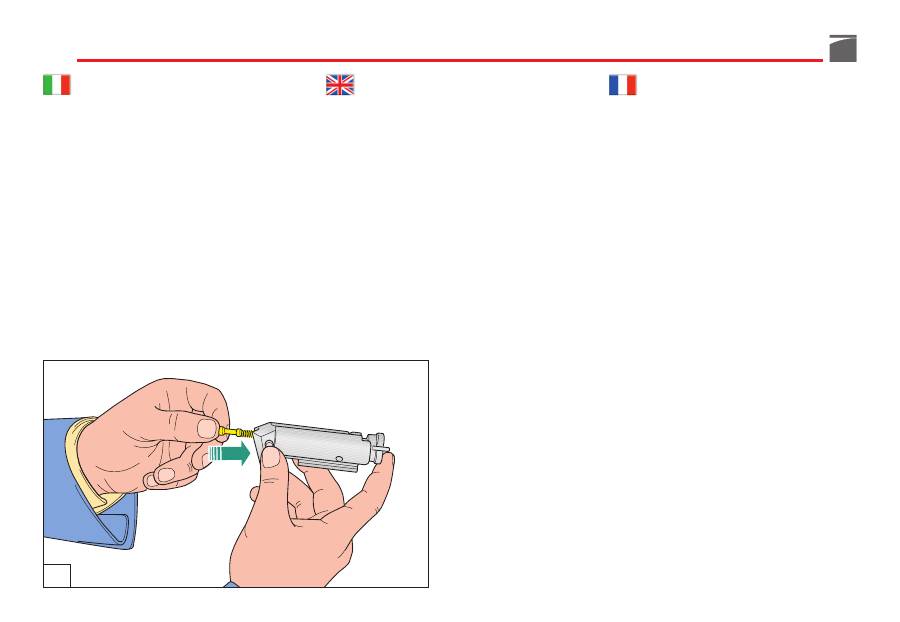
6) Inserire
il percussore
con la sua molla nel
foro nell’otturatore (fig. 56).
ATTENZIONE:
accertarsi di aver montato
sempre
la molla del percussore.
7) Inserire
il perno arresto
percussore nel
suo foro, in modo che blocchi il percus-
sore (fig. 57).
NOTE:
the reference line
on top of the pin
must be
visible and aligned
with the bolt’s
centerline (fig. 55).
6) Insert
the firing pin
and the firing pin
spring inside the bolt (fig. 56).
NOTE:
always
make sure that the firing pin
has been inserted together with its spring.
7) Insert the firing pin
retaining pin
in its
seat, so as to block the firing pin (fig. 57).
ATTENTION:
la ligne
de référence marquée
sur l’extrémité de l’axe doit être
visible et ali-
gnée
avec l’axe longitudinal du groupe obtu-
rateur (fig. 55).
6) Introduire
le percuteur
avec son ressort
dans l’orifice de son logement de l'obtu-
rateur (fig. 56).
ATTENTION:
assurez-vous que vous avez
toujours
monté le ressort du percuteur.
7) Introduire
l’axe d’arrêt
du percuteur dans
l'orifice de son logement de manière à ce
qu’il bloque le percuteur (fig. 57).
56
119
ACHTUNG:
Der am Zapfenende markierte
Strich
muss
sichtbar
sein und nach der
Längs-
achse
des Verschlussblockes ausgerichtet sein
(Abb. 55).
6) Den
Schlagbolzen
zusammen mit der
Schlagbolzenfeder in den Verschlussblock
einsetzen (Abb. 56).
ACHTUNG:
Stets
prüfen, ob der Schlagbolzen
zusammen mit der Schlagbolzenfeder einge-
baut ist.
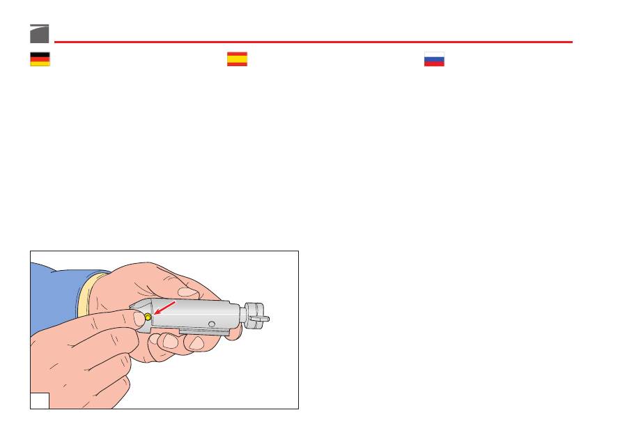
7) Den
Fixierstift
des Schlagbolzens in die
vorgesehene Bohrung einsetzen, um ihn
somit zu blockieren (Abb. 57).
ATENCIÓN:
la línea
de referencia marcada
en la extremidad del eje debe estar
a la vista
y alineada
con el eje longitudinal del grupo
obturador (fig. 55).
6) Introduzca
el percutor
con su resorte en
el agujero de alojamiento que se encuen-
tra en el obturador (fig. 56).
ATENCIÓN:
asegúrese
siempre
de haber
montado el resorte del percutor.
7) Introduzca el
eje de parada
del percutor
en su agujero de alojamiento de manera
que detenga el percutor (fig. 57).
ВНИМАНИЕ:
линия
, маркированная на
конце шпильки, должна быть
видна и
выровнена
по продольной оси узла затвора
(рис. 55).
6) Вставьте боек
с его пружиной
в
отверстие затвора (рис. 56).
ВНИМАНИЕ:
убедитесь в том, что пружина
бойка установлена.
7) Вставьте
фиксатор
бойка в отверстие
так, чтобы он блокировал боек (рис. 57).
57

