Yamaha KMA-700: CONNECTIONS
CONNECTIONS: Yamaha KMA-700
Table of contents
- IMPORTANT SAFETY INSTRUCTIONS
- FCC INFORMATION (for US customers)
- Caution: Read this before operating your unit
- CONTENTS
- HANDLING PRECAUTIONS BEFORE CONNECTING
- NAMES OF PARTS AND THEIR FUNCTIONS Front panel
- NAMES OF PARTS AND THEIR FUNCTIONS Rear panel
- NAMES OF PARTS AND THEIR FUNCTIONS
- SYSTEM CONNECTIONS
- CONNECTIONS
- CONNECTIONS
- CONNECTIONS
- CONFIGURATION DIAGRAM
- REMOTE CONTROL
- REMOTE CONTROL
- GENERAL OPERATION
- SETUP MODE
- SETUP MODE
- TROUBLESHOOTING MAINTENANCE
- AFTER-SALES SERVICING KARAOKE ETIQUETTE COPYRIGHT
- SPECIFICATIONS
CONNECTIONS
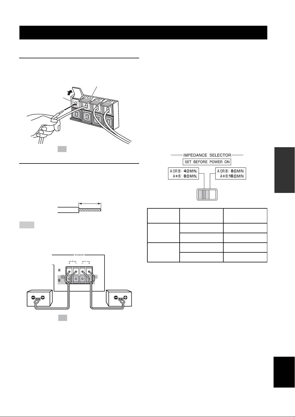
■ Connecting speaker cords
■ Important precautions for speaker
connection
1 Pull the lever up to open, then insert the
• The maximum outputs of this unit are as follows:
KMA-700..................................................120 W + 120 W
conductor wire into the hole.
KMA-500..................................................100 W + 100 W
(–) cord to (–) terminal
Accordingly, the maximum input power of the speakers
used must exceed the above.
(+) cord to
• Use Yamaha speakers to prevent any trouble or
(+) terminal
damage caused by mismatching.
[For KMA-700]
IMPEDANCE SELECTOR
• Before turning on this unit, be sure to set
IMPEDANCE SELECTOR on the rear panel to the
position whose requirements your speaker system
meets.
The shaded part ( ) is provided for KMA-700 only.
OPERATION
2 Close the lever to secure the conductor wire.
Before connection, strip a section of coating 15 mm
(9/16”) in length from the end of each cord using a
tool such as pliers.
(Low) (High)
15 mm (9/16”)
Switch
If your system
Speaker
position
uses:
impedance level
Note
One speaker system
4
Ω or higher
Be careful that the cord conductors projected from a terminal do
Low
Two speaker systems
8
Ω or higher
not contact with another cord. Contact from the conductors of
different speaker cords may cause damage to the system.
One speaker system
8
Ω or higher
High
Two speaker systems
16
Ω or higher
• Do not change IMPEDANCE SELECTOR setting
while the power to this unit is on, otherwise this unit
Right
Left
may be damaged.
speaker
speaker
Connection examples
The minimum speaker impedance is 4 Ω. If two 6 Ω
speaker systems are connected in parallel, this will exceed
the design value and trigger a safety protector device.
When two speaker systems are used and the protector is
The shaded part ( ) is provided for KMA-700 only.
frequently activated, the speaker systems should be
connected serially instead.
English
7 En
