HEIDENHAIN MSE 1120: MSE 1110, MSE 1310 Installation Instructions
MSE 1110, MSE 1310 Installation Instructions: HEIDENHAIN MSE 1120

English
MSE 1110, MSE 1310
Installation Instructions
Operating Instructions available at www.heidenhain.de
1. How to use these instructions
Contents
The installation instructions contained in this document provide the information necessary
How to use these instructions .................16
to install this product. This information is just a part of the information available in the
Model information ....................................18
Operating Instructions (ID 1066850-xx). The Operating Instructions can be downloaded
Safety ........................................................19
from www.heidenhain.de.
Specifications ............................................ 20
These instructions are intended for use by personnel qualified to install and maintain the
Mounting ................................................... 21
HEIDENHAIN MSE 1000.
Installation .................................................25
A qualified person is someone whose technical education, knowledge and experience,
Maintenance .............................................27
as well as knowledge of the relevant system of rules qualifies the person to evaluate the
delegated task and recognize possible hazards.
16
Messages shown in these instructions
The following examples show how safety, property damage and general advice messages
are shown in these instructions. Read and understand these types of messages before
proceeding to prevent personal injury or property damage.
Messages about other safety messages. These supplemental directives do
not address specific hazards, but instead provide information that promotes
awareness and use of specific safety messages.
Warning!
Messages that provide information about the nature of a hazardous situation,
the consequences of not avoiding a hazardous situation, and methods for
avoiding a hazardous situation.
Notice
Messages that provide information primarily about situations that can lead to
property damage, the potential consequences of not avoiding the situations, or
methods for avoiding the situations and general advice messages.
Fonts used in these instructions
Items of special interest or concepts that are emphasized to the user are shown in bold
type.
17
2. Model information
9
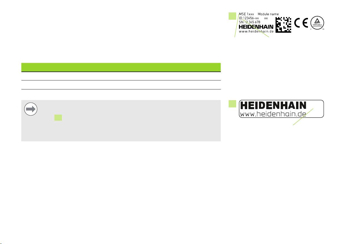
This guide covers multiple products. Whenever possible the product name shown on
the cover page is used. When a feature pertains to a specific product variant the specific
product name or the product name and the ID are shown. In some cases an “x” is shown
Product name ID
in the product name to represent the described feature is available on multiple product
ID label
variants and types.
This guide covers specifications, mounting and installation for the following models:
Product name ID
MSE 1114 747499-01
MSE 1314 747503-01
MSE 1318 747504-01
Notice
13
Verify that these Installation Instructions are valid by matching the Index on the
label
13
with the Index listed at www.heidenhain.de. If these instructions are
not valid, download the applicable Installation Instructions from
Index
www.heidenhain.de.
Index label
An index may not be present on all products.
18
3. Safety
The following messages provide safety information for preventing personal injury and
product damage:
Read and understand these instructions before use to avoid the possibility of
personal injury or death.
Hazardous live parts may be exposed if the unit is opened. Do not open the
unit. There are no serviceable items inside.
The protection provided by the equipment may be impaired if used in a manner
not specified. Do not use this product in any way other than its intended use.
Notice
For safety, operation and handling of the unit, keep this document for future
reference. This document must be kept within reaching distance of the product.
19
4. Specifications
The MSE 1000 is an advanced system for performing production integrated
measurements at high levels of precision and accuracy. The modules described in these
instructions are designed for indoor use only. The MSE 1000 components shall only be
installed as described in these instructions. Mounting, installation and maintenance are to
be performed by qualified personnel only.
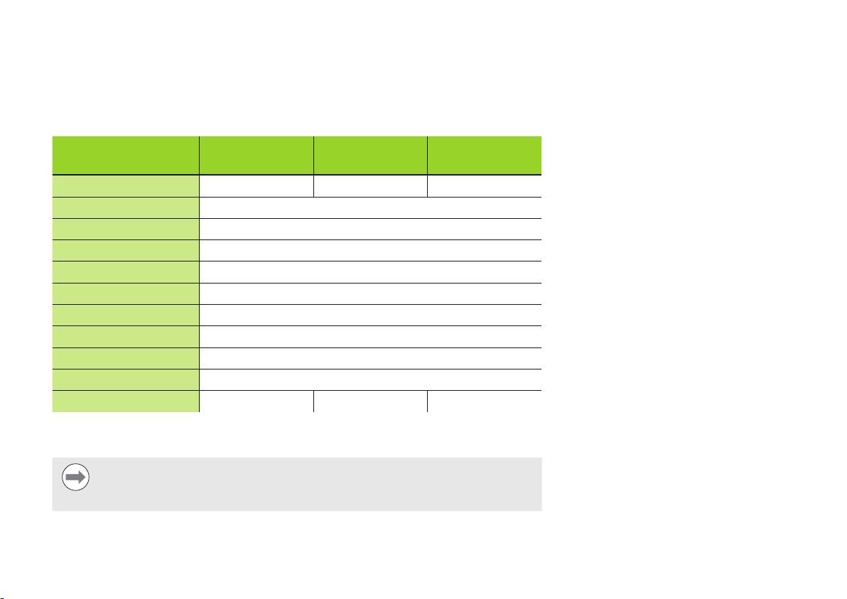
MSE 1114
MSE 1314
MSE 1318
ID 747499-01
ID 747503-01
ID 747504-01
1)
Power consumption
3.5 W 3.3 W 4.4 W
Data transfer
Standard Ethernet, IEEE 802.3
Addressing
Fixed IP address or DHCP
Operating temperature
0 °C ... 45 °C
Storage temperature
-20 °C ... 70 °C
Relative humidity
80 %
Altitude
2000 m
Degree of protection
IP65
Overvoltage category
II, intended to be supplied from the building wiring
Pollution degree
2
Mass
620 g 480 g 740 g
1)
Power requirement of the module. Connected length gauges and encoders must be
considered additionally.
Notice
Refer to the MSE 1000 Product Information (ID 736907-xx) for power
consumption calculation examples.
20
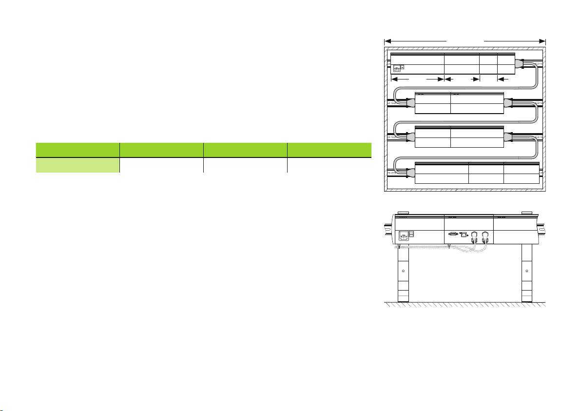
19” / 483 mm
5. Mounting
MSE 1000 modules are designed to be mounted on a standard 35 mm, DIN EN 50022
rail in an electrical cabinet or on a mounting stand (accessory). The individual modules are
plugged onto each other and fixed together with a lock creating a module chain.
Size 3 Size 2 Size 1
In its basic configuration, the MSE 1000 consists of a power supply module and a base
module. A base module provides data interface connections for foot switch control
and network communications in addition to encoder connections. The MSE 1000 can
be expanded by further modules as needed. In all, up to 250 axes or channels can be
configured.
Module sizes Size 1 Size 2 Size 3
Width
53 mm 106 mm 159 mm
19”electrical cabinet mounting
Mounting stand (accessory)
21
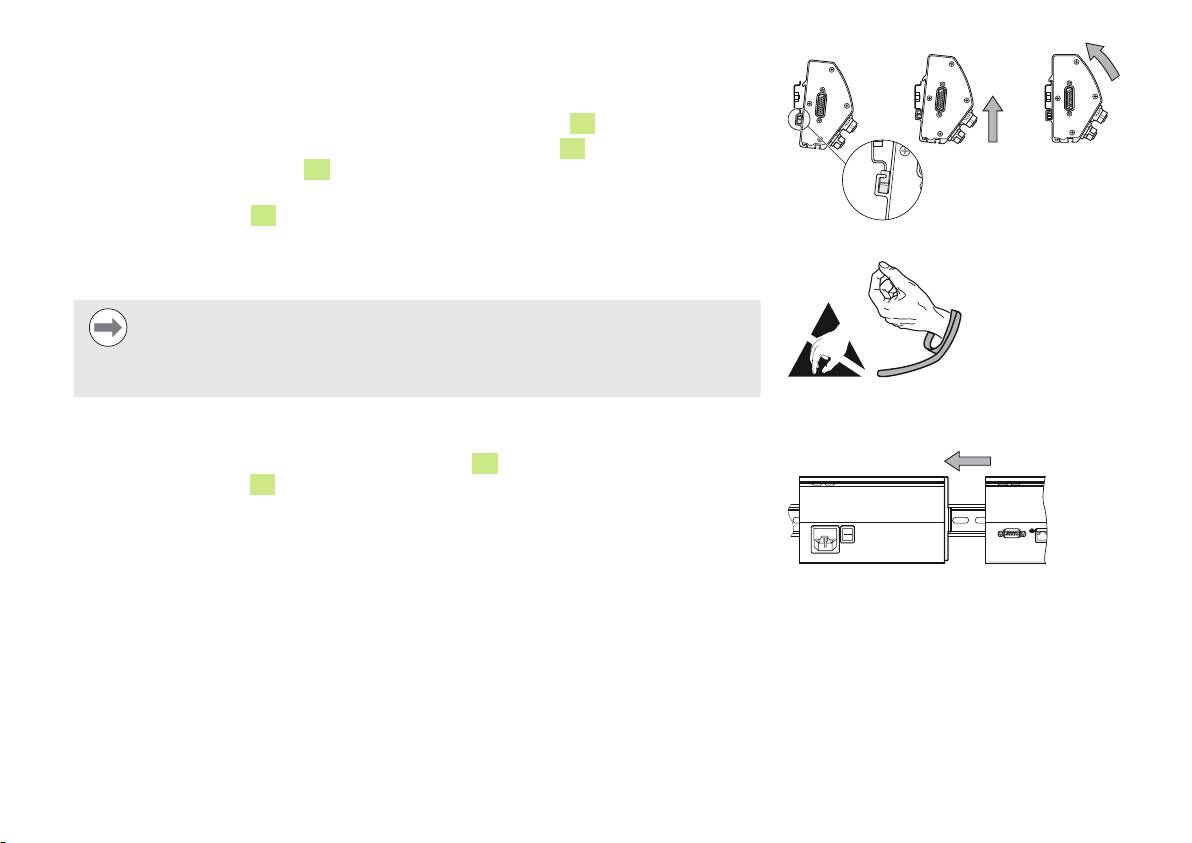
Mounting a module
To mount a module:
Verify power is removed from all power supply modules in the module chain
Align the bottom edge of the DIN rail with the bottom channel
12
of the module
Gently apply upward pressure, depressing the DIN rail spring
11
and inserting the DIN
rail into the bottom channel
12
of the module
While maintaining upward pressure, rotate the top of the module towards the DIN rail
until the top channel
10
of the module is aligned above the DIN rail
Mounting a module
Gently release the upward pressure, locking the module onto the DIN rail
Connecting modules
Notice
This product contains components that can be damaged by electrostatic
discharge (ESD). Observe precautions for handling ESD sensitive devices and
never touch connector pins unless properly grounded.
Observe ESD handling precautions
To connect modules:
Verify power is removed from all power supply modules in the module chain
Slide the right module to the left until the lock tab
3
of the left module engages with
the lock tab receiver
8
of the right module
Connecting modules
22
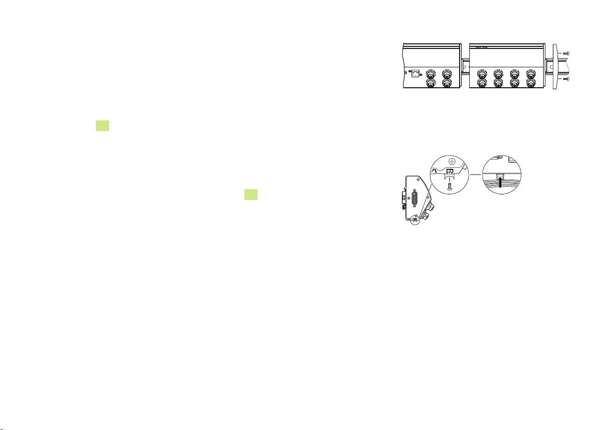
Installing right end cover
Left and right end cover kits are provided with each power supply module for covering
open module ends. The left end cover is mounted on the first power supply module in the
chain.
To install the right end cover:
Installing right end cover
Insert the right end cover into the right side of the last module in the chain
Insert end cover screws through the end cover mounting holes and into the end cover
screw holes
14
on the module
Using a cross-head screwdriver, tighten the screws
Installing cable mounting hardware
A cable mounting hardware kit is provided with each module for routing cables. Each kit
contains two sets of mounting hardware.
Insert the M3 hex nut into the cable mounting slot
16
on the bottom of the module
Insert the M3 screw through the cable tie holder and fasten to the M3 hex nut using a
cross-head screwdriver
Insert the cable tie through the cable tie holder and fasten cables
23
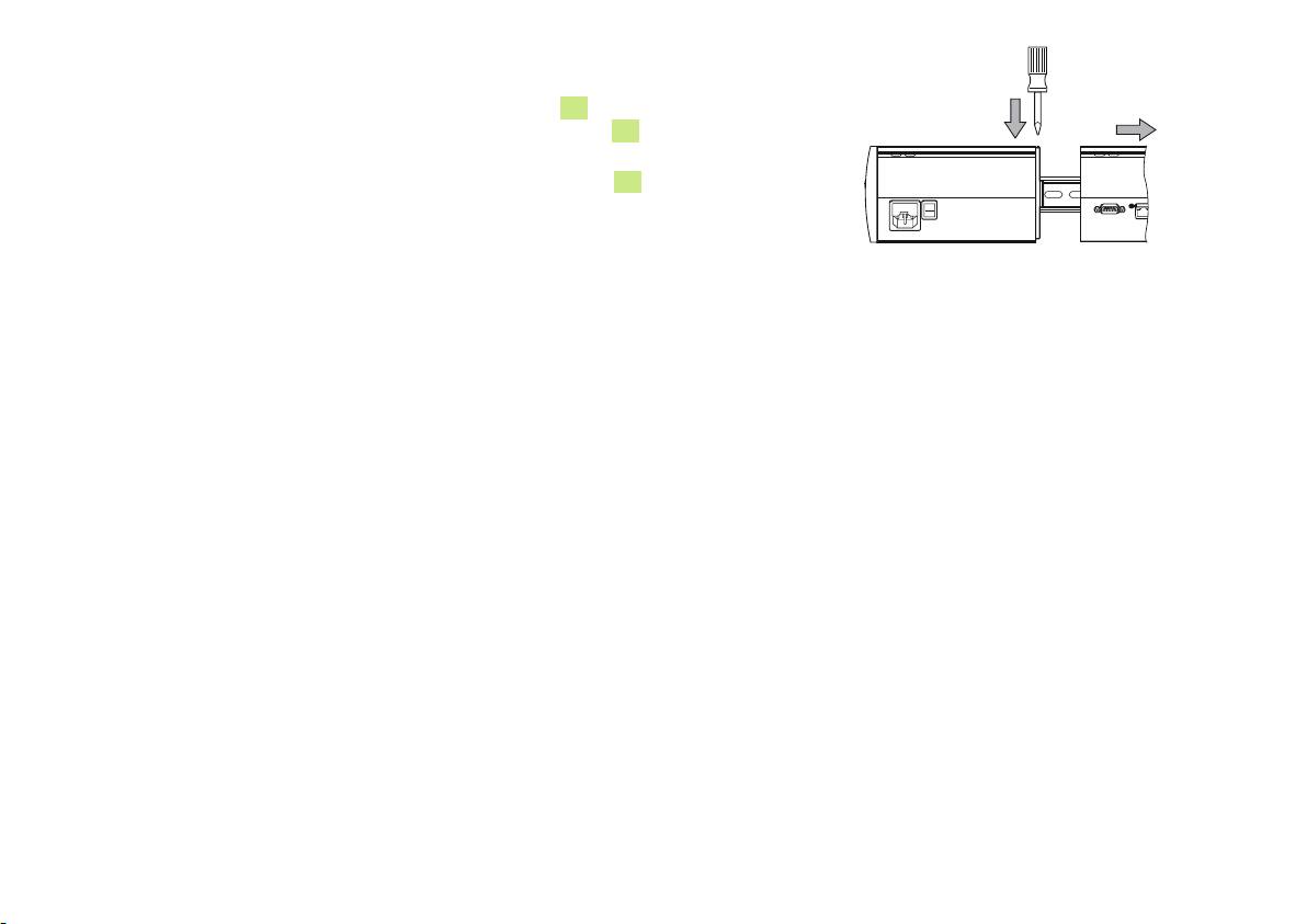
Releasing a module
Verify power is removed from all power supply modules in the module chain
Press a flat-edge screwdriver into the lock tab receiver
8
opening at the top
left of the right hand module and press down on the lock tab
3
of the left hand
module to release the module
Gently apply upward pressure, depressing the DIN rail spring
11
While maintaining upward pressure, rotate the top of the module away from the DIN
rail
Gently release the upward pressure, releasing the module from the DIN rail
Releasing a module
24
6. Installation
Interfaces
Power indicator LED
The safety of any system incorporating the use of this product is the
1
responsibility of the assembler or installer of the system.
Network LED indicator
2
Notice
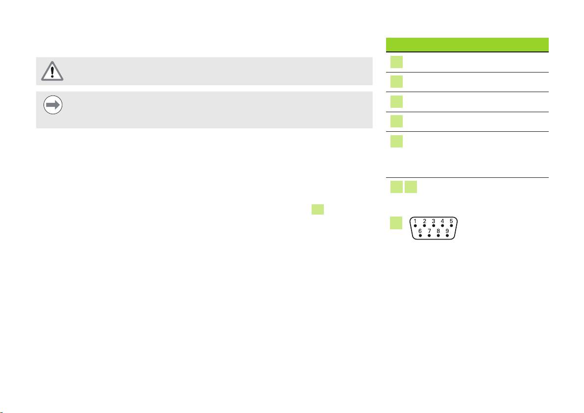
Foot switch connection
4
Do not engage, or disengage any connections while the unit is under power.
Damage to internal components may result.
RJ-45 for network connection
5
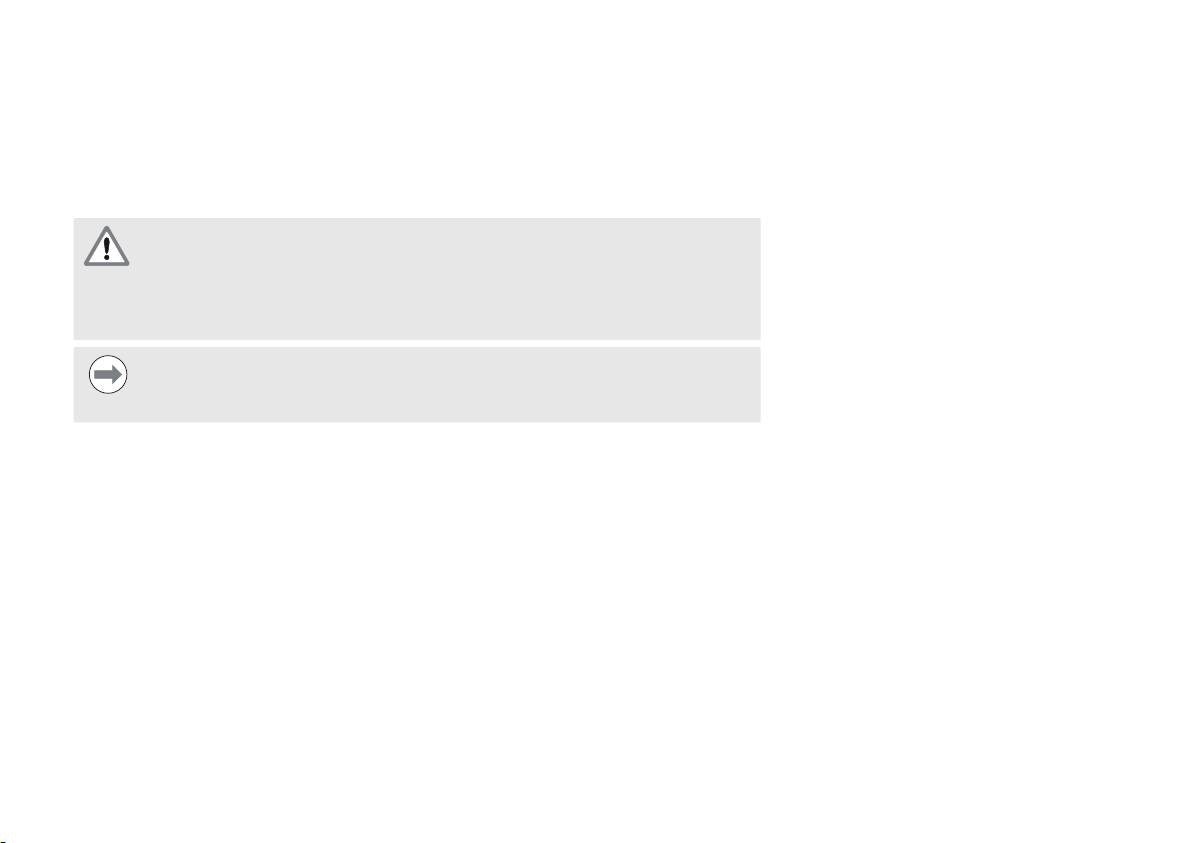
Encoder inputs: X11 ... X18
Data interface connections
6
axis for linear and rotary EnDat
Connecting a foot switch (MSE 1114)
interface encoders. The number
of axes varies by module.
This product can be used with HEIDENHAIN foot switch ID 681041-03.
To connect a foot switch:
Module connectors
7
15
Verify power is removed from all power supply modules in the module chain
Connect the foot switch cable connector to the foot switch connection
4
on the
module and tighten the cable connector screws until they are snug
4
Foot switch connector
25
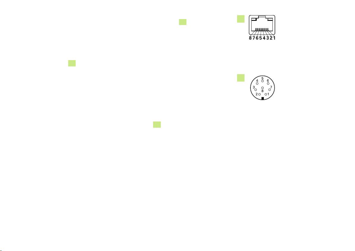
Connecting a network cable (MSE 1114)
5
MSE modules communicate with a PC through an RJ-45 connection
5
located on the
base module. Use a straight-through cable when connecting to a hub or a crossover cable
when connecting directly to a PC.
To connect a network cable:
RJ-45 connector
Verify power is removed from all power supply modules in the module chain
With the cable connector locking tab facing up, insert the cable connector into the
RJ-45 connection
5
on the module until the tab locks into place
Connecting an encoder
6
This product can be used with HEIDENHAIN length gauges, linear encoders and rotary
encoders that provide EnDat signals. The connecting cable must not exceed 100 meters in
length.
To connect an encoder:
Encoder connector
Verify power is removed from all power supply modules in the module chain
Align the encoder cable connector notch with the module encoder connection notch
Insert the cable connector into the encoder connection
6
and tighten the cable
connector by turning clockwise until it is snug
26
7. Maintenance
The maintenance procedures described in these instructions may be required
during installation of the product. For additional maintenance information, refer to
the Operating Instructions (ID 1066850-xx).
Cleaning
Warning! Risk of electrical shock
While cleaning it is possible to conduct electricity from hazardous live parts if
liquid enters the product.
To avoid the hazard, always power off the product, disconnect the power cable
and never use a cloth that is dripping or saturated with water.
Notice
Never use abrasive cleaners, strong detergents or solvents to avoid damage to
the product.
To clean:
Verify power is removed from all power supply modules in the module chain
Wipe exterior surfaces with a cloth dampened with water and a mild household
detergent
27
Оглавление
- MSE 1110 MSE 1310
- MSE 1110, MSE 1310 Product overview
- MSE 1110, MSE 1310 Installationsanleitung
- MSE 1110, MSE 1310 Installation Instructions
- MSE 1110, MSE 1310 Guide d'installation
- MSE 1110, MSE 1310 Istruzioni di installazione
- MSE 1110, MSE 1310 Instrucciones de instalación
- MSE 1110, MSE 1310 Installationsanvisning
- MSE 1110, MSE 1310 Installatie-instructies
- MSE 1110, MSE 1310 Instruções de Instalação
- MSE 1110, MSE 1310 Instrukcja instalacji
- MSE 1110, MSE 1310 Инструкция по установке
- MSE 1110, MSE 1310 Kurulum Talimatları
- MSE1110、MSE1310 設置説明書
- MSE1110,MSE1310 安装说明
- MSE1110,MSE1310 安裝說明
- MSE 1110, MSE 1310 Dimensions, accessories and connector pin assignments
