Graff 1/2” AND 3/4” THERMOSTATIC MIXING VALVE: инструкция
Раздел: Бытовая, кухонная техника, электроника и оборудование
Тип: Кулер для воды
Инструкция к Кулеру для воды Graff 1/2” AND 3/4” THERMOSTATIC MIXING VALVE
For care, use soft towel with soap and water only!
Under no circumstances should you use any chemicals.
ATTENTION!
Pour le nettoyage utiliser seulement une serviette douce, du savon et de l’eau!
En aucun cas n’utiliser les produits chimiques quelconques!
ATTENTION!
Para el cuidado, utilice solamente una toalla suave con jabón y aqua!
Bajo ninguna circunstancia no use productos químicos.
ATENCIÓN!
c u t t i n g e d g e d e s i g n
Instructions for assembly and use • Montage- und Gebrauchsanweisung • Notice technique montage et utilisation • Инcтрукция по монтажу и обслуживанию • Instrucción de Montaje y Servicio • Manuale di Montaggio e Uso
THERMOSTATISCHES MISCHVENTIL 1/2” UND 3/4”
VANNE DE MÉLANGE THERMOSTATIQUE 1/2” ET 3/4”
•
ТЕРМОСТАТИЧЕСКИЙ СМЕШИВАЮЩИЙ КЛАПАН 1/2” И 3/4”
LA VÁLVULA MEZCLADORA TERMOSTÁTICA 1/2” Y 3/4”
•
VALVOLA MISCELATRICE TERMOSTATICA 1/2” I 3/4”
Dear Customer
Thank you for choosing our product.
We hope the item you have purchased
can fulfill all your expectations our
products are technologically advanced
and designed on the basis of our many
years of experience in the production of
sanitary fittings.
Sehr geehrte Damen und Herre
Wir bedanken uns für die Wahl un-
seres Produktes. Wir hoffen, dass wir mit
unserem technologisch fortgeschrittenen
Produkt, dass auf Basis mehrjährigen
Erfahrungen bei der Produktion von Sa-
nitärarmaturen entwickelt wurde, Ihre
Erwartungen erfüllt haben.
Cher client
Nous vous remercions pour savoir
choisi notre produit. Nous sommes cer-
tains de pouvoir satisfaire pleinement
à vos attentes grâce à notre riche offre
de produits d’un niveau technologique
avancé qui résulte de notre longue expé-
rience en fabrication de la robinetterie et
des accessoires des salles de bains.
Уважаемые господа
Благодарим за выбор нашего
продукта Надеемся что полностью
удовлетворим Ваши ожидания, вво-
дя в эксплуатацию технологически
усовершен ствованное изделие, за-
проектированное на базе многолет-
него опыта в области производства
санитарной арматуры.
Muy Seńores Míos
Les agradecemos por elegir nuestro
producto. Esperamos que cumplamos
Sus deseos entre gándoles un producto
de una tecnología avanzada, diseńado a
base de la experiencia de muchos ańos en
la producción de accesorios sanitarios.
Cari Clienti
Vi ringraziamo per aver scelto il
nostro prodotto. Speriamo, di aver sod-
disfatto completamente le Vostre aspet-
tative, offrendo Vi un prodotto tecnologi-
camente avanzato, progettato in base ad
una esperienza di molti anni nell’ambito
di produzione degli accessori sanitari.
GB
D
F
RUS
E
I
Verunreinigungen bitten wir mittels Wasser mit Seife und mit weichem Lappen
beseitigen! In keinem Falle chemische Mittel verwenden.
ACHTUNG!
Загрязнения следует удалять водой с мылом и мягкой тряпочкой!
Ни в коем случае нельзя применять химические средства.
ВНИМАНИЕ!
Attenzione! Si prega di pulire usando acqua e sapone ed un panno morbido!
In nessun caso usare detergenti chimici.
ATTENZIONE!
1
IOG 2194.00
Rev. 2 May 2010
GB D
F RUS E
I
1/2” AND 3/4” THERMOSTATIC MIXING VALVE
FLOW RATE INFORMATION
During the selection of number of shower outlets please take into consideration the flow
rates of the thermostatic valves.
l
The 1/2” thermostatic mixing valve has a flow rate of 37 l/min. at 3 bar.
l
The 3/4” thermostatic mixing valve has a flow rate of 58 l/min. at 3 bar.
INFORMATION ÜBER DIE DURCHFLUSSMENGE
Bei der Auswahl der Anzahl der Auslaufspunkte (Abnehmer) soll man auf die Durchflus-
smenge der thermostatischen Ventile achten.
l
Thermostatisches Mischventil 1/2” weist den Erguss von 37 l/min beim Druck von 3 bar auf.
l
Thermostatisches Mischventil 3/4” weist den Erguss von 58 l/min beim Druck von 3 bar auf.
INFORMATION SUR LE DEBIT
En choisissant le nombre de points de sortie (récepteurs), il convient de prendre en compte le
débit des vannes thermostatiques.
l
La vanne de mélange thermostatique 1/2” a un débit de 37 l/min sous une pression de
3 bars.
l
La vanne de mélange thermostatique 3/4” a un débit de 58 l/min sous une pression de
3 bars.
ИНФОРМАЦИЯ ОБ ОБЪЕМЕ ТЕЧЕНИЯ
При определении количества пунктов приема воды следует обратить внимание на
объем течения термостатических клапанов.
l
Термостатический смешивающий клапан 1/2” – употребление 37 л./мин. при
давлении 3 бара (0,3 MPa - мегапаскаля).
l
Термостатический смешивающий клапан 3/4” – употребление 58 л./мин. при
давлении 3 бара (0,3 MPa - мегапаскаля).
INFORMACIÓN DE INTENSIDAD DE FLUJO
En la selección del número de bocas de salida de la ducha, tenga en cuenta los datos de
intensidad de flujo las válvulas termostáticas.
l
La válvula mezcladora termostática 1/2” tiene la intensidad de flujo de 37l/min. con 3 bar.
l
La válvula mezcladora termostática 3/4” tiene la intensidad de flujo de 58l/min. con 3 bar.
DIMENSIONE DEL FLUSSO
Scegliendo la quantità di punti in uscita (di utenza) bisogna prendere in considerazione la
dimensione del flusso attraverso la valvola termostatica.
l
La valvola miscelatrice termostatica 1/2” ha la portata di 37 l/min con la pressione di 3 bar.
l
La valvola miscelatrice termostatica 3/4” ha la portata di 58 l/min con la pressione di 3 bar.
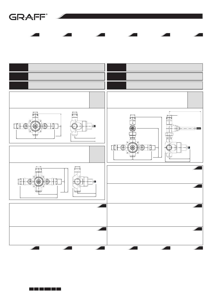
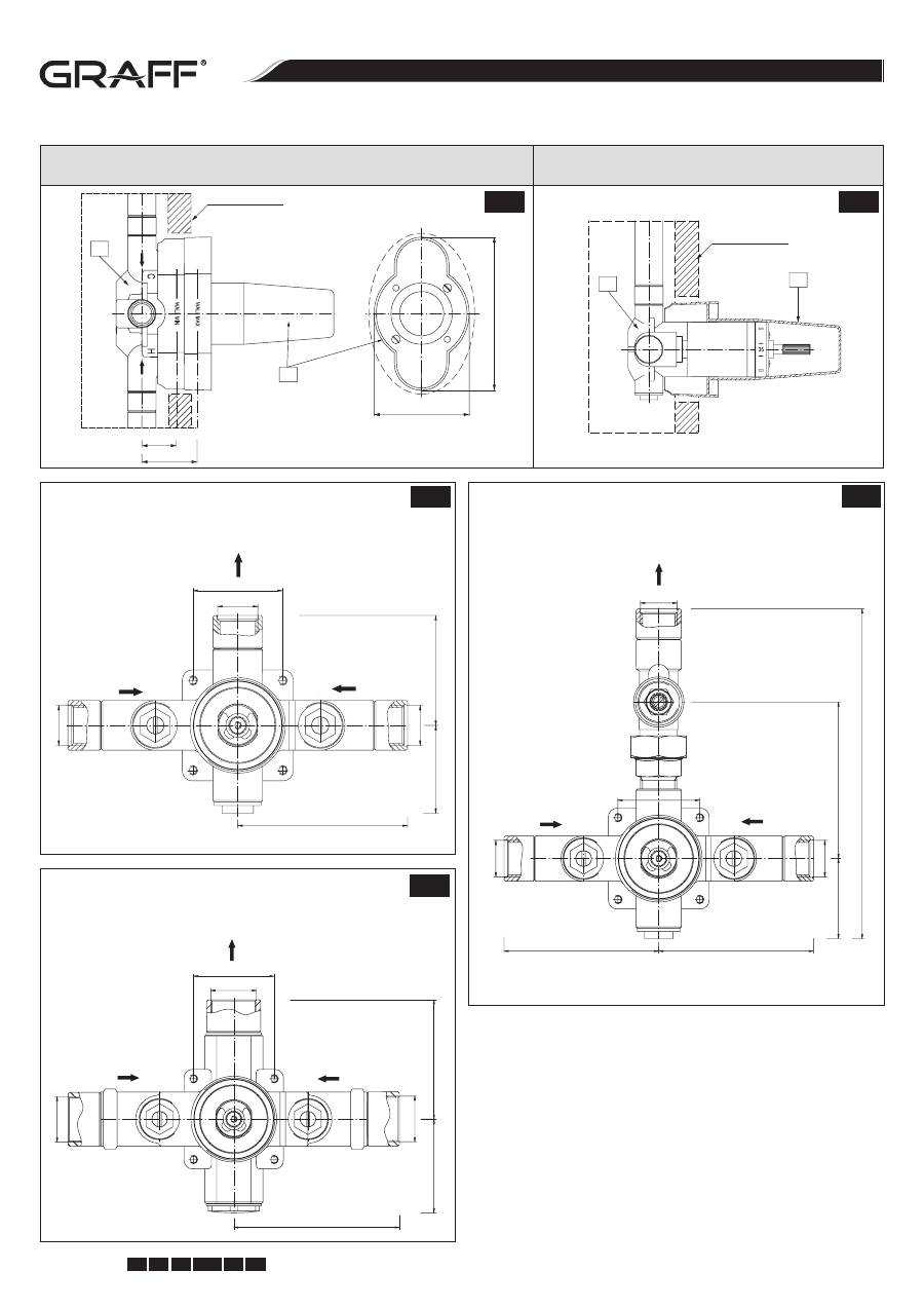
2194370
1/2” concealed thermostatic valve – rough
1/2” UP- Thermostat – UP-Teil
Thermostat 1/2”- corps à encastrer
Термостатический переключатель 1/2” - внутренний элемент
Termostato 1/2” empotrado - parte interna
Termostatico da incasso 1/2” - parti grezze
2194380
3/4" concealed thermostatic valve – rough
3/4” UP- Thermostat – UP-Teil
Thermostat 3/4”- corps à encastrer
Термостатический переключатель 3/4” - внутренний элемент
Termostato 3/4” empotrado - parte interna
Termostatico da incasso 3/4” – parti grezze
Tools required for assembly:
l
1/2” and 3/4” nominal
copper tubing and fittings,
l
wrenches,
l
thin-bladed knife,
or screwdriver,
l
hacksaw or tubing cutter,
l
thread sealant,
l
thermometer.
Für die Montage werden folgende
Werkzeuge benötigt:
l
Verbindungsstücke
und Kupferrohre
1/2” und 3/4”,
l
Verstellbarer Schlüssel,
l
Schraubenzieher,
l
Metallsäge,
l
Gewindedichtung,
l
Thermometer.
Outils nécessaires au montage :
l
raccords et tuyaux en cuivre
1/2” et 3/4”,
l
clé à molette,
l
tournevis,
l
scie à métaux,
l
joint pour filetage,
l
thermomètre.
Для монтажа необходимы
следующие инструменты:
l
соединители и медные
трубки 1/2” и 3/4”,
l
разводной ключ,
l
отвертка,
l
пила для металла (лобзик),
l
уплотнитель резьбы,
l
термометр.
Para la instalación se necesitan
las siguientes herramientas:
l
manguitos nominales
1/2” y 3/4”,
l
llaves,
l
cortaplumas
o destornillador plano,
l
sierra para metal o corta,
l
obturador de la rosca.
l
termómetro.
Per il montaggio servono
i seguenti utensili:
l
raccordi e tubi in rame
1/2” e 3/4”,
l
chiave registrabile,
l
cacciavite,
l
sega per metallo,
l
guarnizione del filetto,
l
termometro.
GB
GB
D
D
F
F
RUS
RUS
E
E
I
I
89
89
Rp
1/
2
46
57.5
Rp1/2
Rp1/2
Rp1/2
97
116
89
89
Rp1/2
Rp1/2
149
Rp1/2
Rp
1/
2
46
90
190
98
116
2194390
1/2 ‘’ concealed thermostatic and cut-off valve – rough
1/2’’ UP- Thermostat mit Absperrventil – UP-Teil
Module de thermostat avec robinet d’arrêt 1/2 ‘’ - corps à encastrer
Термостатический переключатель 1/2 - внутренний элемент
Grupo termostático empotrado 1/2’’- parte interna
Termostatico da incasso con rubinetto d’arresto 1/2’’ – parti grezze
Rp3/4
69,5
54,5
124
Rp
3/
4
97
193
Rp3/
4
Rp3/4
96
119
c u t t i n g e d g e d e s i g n
Instructions for assembly and use • Montage- und Gebrauchsanweisung • Notice technique montage et utilisation • Инcтрукция по монтажу и обслуживанию • Instrucción de Montaje y Servicio • Manuale di Montaggio e Uso
2
IOG 2194.00
Rev. 2 May 2010
GB D
F RUS E
I
THERMOSTATISCHES MISCHVENTIL 1/2” UND 3/4” VANNE DE MÉLANGE THERMOSTATIQUE 1/2” ET 3/4” • ТЕРМОСТАТИЧЕСКИЙ СМЕШИВАЮЩИЙ КЛАПАН 1/2” И 3/4” LA VÁLVULA MEZCLADORA TERMOSTÁTICA 1/2” Y 3/4” • VALVOLA MISCELATRICE TERMOSTATICA 1/2” I 3/4” 1/2” AND 3/4” THERMOSTATIC MIXING VALVE
3
~ 99
ø5
0
150
150
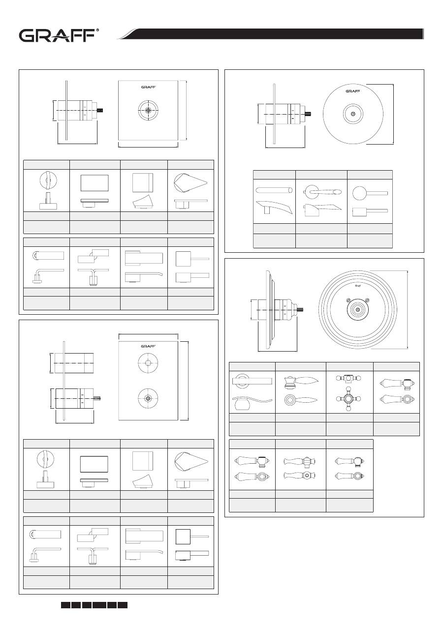
LM14S
LM31S
C10S
LM23S
LUNA, SADE, TARGA
2356150 (PC),
2356160 (SN)
SOLAR, STRUCTURE
2356050 (PC), 2356060 (SN),
2356070 (PC/BK)
FONTAINE
2356350 (PC),
2356360 (SN)
STEALTH
2356250 (PC),
2356260 (SN)
LM40S
C9S
LM38S
LM39S
IMMERSION
2356500 (PC),
2356510 (SN)
IMMERSION
2356450 (PC),
2356460 (SN)
QUBIC
2356700 (PC)
QUBIC TRE
2390100 (PC)
~99
ø50
ø15
0
TRANQUILITY
2356550 (PC),
2356560 (SN)
ATRIA
2356800 (PC),
2356810 (SN)
M.E.25/M.E.
2356750 (PC)
LM24S
LM25B
LM37S
ø50
ø50
~96
150
200
LM14S
LM31S
C10S
LM23S
LUNA, SADE, TARGA
2356100 (PC),
2356110 (SN)
SOLAR, STRUCTURE
FONTAINE
2356300 (PC),
2356310 (SN)
STEALTH
2356200 (PC),
2356210 (SN)
2356000 (PC), 2356010 (SN),
2356020 (PC/BK)
LM40S
C9S
LM38S
LM39S
IMMERSION
2356600 (PC),
2356610 (SN)
IMMERSION
2356400 (PC),
2356410 (SN)
QUBIC
2356650 (PC)
QUBIC TRE
2390000 (PC)
ø50
ø196
~97
LM20S
LM14S
C2S
LC1S
LM34
LM22S
LM15S
BALI
2356900 (PC),
2356910 (SN)
TOPAZ
2364000 (PC)
CANTERBURY
2364200 (PC)
CANTERBURY
2364150 (PC)
CANTERBURY
2364100 (PC)
LAUREN
2356950 (PC)
NANTUCKET
2364050 (PC)
2
c u t t i n g e d g e d e s i g n
Instructions for assembly and use • Montage- und Gebrauchsanweisung • Notice technique montage et utilisation • Инcтрукция по монтажу и обслуживанию • Instrucción de Montaje y Servicio • Manuale di Montaggio e Uso
3
IOG 2194.00
Rev. 2 May 2010
GB D
F RUS E
I
THERMOSTATISCHES MISCHVENTIL 1/2” UND 3/4” VANNE DE MÉLANGE THERMOSTATIQUE 1/2” ET 3/4” • ТЕРМОСТАТИЧЕСКИЙ СМЕШИВАЮЩИЙ КЛАПАН 1/2” И 3/4” LA VÁLVULA MEZCLADORA TERMOSTÁTICA 1/2” Y 3/4” • VALVOLA MISCELATRICE TERMOSTATICA 1/2” I 3/4” 1/2” AND 3/4” THERMOSTATIC MIXING VALVE
PRODUCT SPECIFICATION:
1. The thermostatic mixing valve cartridges do not contain an integral stop/
volume control valve (except the
2194390
) model. You must install a sepa-
rate stop/volume control valve downstream of any valve outlet that does
not have an integral shut-off valve. Please refer to fig. 6.1.
2. The
2194390
thermostatic mixing valve contains a single stop/volume con-
trol valve for controlling the water flow through the shower outlet. When
plumbing to the valve’s bath outlet, you must install a separate stop/vol-
ume control valve) downstream from the bath outlet. Refer to fig. 6.2.
3. Determine the correct drain size and capacity for your installation. If two
thermostatic mixing valves are used together, water flow volumes of
95 l/ min. or more are possible, depending upon the water supply pressure.
4. Determine the correct water heater size and capacity for your installation.
A typical shower installation uses an approximate mix of 75% hot water
and 25% cold. A custom shower application using three showerheads can
use about 170 l of hot water in 8 minutes. Choose a water heater large
enough for your installation.
SPEZIFIKATION DES PRODUKTES:
1. Thermostatische Mischventile besitzen keine eingebauten Absperr- oder
Regelventile zur Regelung des Durchflusses (außer Modell
2194390
). Man
soll ein separates Absperr-Regelventil unterhalb jedes Abnehmers montie-
ren, der kein Absperrventil hat. Siehe Zeich. 6.1.
2. Thermostatisches Mischventil
2194390
hat ein Einzel-Absperr-Regelventil
zur Regelung des Wasserdurchflusses über den Brauseauslauf. Beim An-
schluss des Wannenauslaufes soll ein separates Absperr- oder Regelventil
unter dem Auslauf auf die Wanne installiert werden. Siehe Zeich. 6.2.
3. Es soll die richtige Menge und Erguss des Ablaufes bestimmt werden. Wenn
2 thermostatische Ventile gebraucht werden, kann der Wasserdurchfluss
durch das Einlaufgitter 95 l/min. oder mehr, je nach dem Speisewasser-
druck, betragen.
4. Es soll richtige Menge und Erguss des Wassererhitzers bestimmt wer-
den. Eine typische Brauseinstallation verbraucht eine Mischung von 75%
Heißwasser und 25% Kaltwasser. Ein aus 3 Wasserabnehmern (Brauseköp-
fe) bestehender Duschesatz kann ungefähr 170 l Heißwasser in 8 Minuten
verbrauchen. Man soll einen ensprechend großen Wassererhitzer wählen.
SPÉCIFICATIONS DU PRODUIT:
1. Les vannes de mélange thermostatiques ne sont pas équipées de vannes
d’arrêt ou de vannes de contrôle de débit intégrées (à l’exception du mo-
dèle
2194390
). Il convient d’installer une vanne d’arrêt et de contrôle sépa-
rée sous chaque récepteur qui n’est pas équipé d’une vanne d’arrêt inté-
grée. Veuillez vous référer au schéma 6.1.
2. La vanne de mélange thermostatique
2194390
est équipée d’une vanne
unique d’arrêt et de contrôle pour la régulation du débit à l’écoulement
de la douche. Lors du raccordement de la sortie de la baignoire, il convient
d’installer en amont une vanne d’arrêt et de contrôle séparée. Veuillez vous
référer au schéma 6.2.
3. Déterminez le volume et le débit d’écoulement exacts. Si les 2 vannes ther-
mostatiques sont utilisées en même temps, l’écoulement de l’eau par la
grille d’évacuation peut s’élever à plus de 95 l/min, en fonction de la pres-
sion d’alimentation.
4. Déterminez le volume et le débit exacts du chauffe-eau. Une installation
de douche typique utilise un mélange de 75 % d’eau chaude et 25 % d’eau
froide. Le kit de douche composé de 3 points d’écoulement (jets) peut
utiliser environ 170 l d’eau chaude en 8 minutes. Il convient de choisir un
chauffe-eau suffisamment grand.
СПЕЦИФИКАЦИЯ ИЗДЕЛИЯ:
1. Смешивающие термостатические клапаны не имеют встроенных
запорных либо регулирующих течение клапанов (кроме модели
2194390
). Следует установить отдельный регулирующе - запорный
клапан ниже каждого отдельного приемника воды без встроенного за-
порного клапана. Посмотрите рис. 6.1.
2. Смешивающий термостатический клапан
2194390
имеет один регули-
рующе – запорный клапан для регуляции течения воды через душевое
отверстие. При подключении вывода на ванну следует установить от-
дельный смешивающее - термостатический клапан до вывода на ван-
ну. Посмотрите рис. 6.2.
3. Определите соответствующий объем и количество излива. При упо-
треблении 2 термостатических клапанов, совместный излив воды че-
рез сливную решетку может составить 95 л./мин. или больше, в зависи-
мости от снабжающего давления.
4. Определите соответствующий объем и отдачу подогревателя воды.
Типичная душевая установка потребляет смесь 75% горячей и 25% хо-
лодной воды. Душевой комплект из 3 приемников воды (душевых го-
ловок – сопол) может потребить примерно и 170 горячей воды за 8 ми-
нут. Следует подобрать соответствующе мощный подогреватель воды.
ESPECIFICACIÓN DEL PRODUCTO:
1. Los cartuchos de la válvula termostática mezcladora no llevan integrada
la válvula de cierre/control de flujo (excepto los modelos
2194390
). Usted
tiene que instalar una válvula de cierre/control de flujo por separado, abajo
de la salida de cualquier válvula que no tenga integrada la válvula de cierre.
Por favor, ver dis 6.1.
2. La válvula mezcladora termostática
2194390
lleva integrada una válvula
de cierre/control de flujo para controlar el flujo del agua que pasa a través
del cabezal de la ducha. Instalándola usted tiene que colocar una válvula
de cierre/control flujo por separado, abajo del desagüe de la bañera. Ver
dis 6.2.
3. Determine el tamaño del desagüe correcto y la capacidad de su instala-
ción. Si dos válvulas mezcladoras van usadas juntas, es posible obtener el
flujo de agua de 95 lpm o más, según la presión del agua suministrada.
4. Determine el tamaño correcto del calentador del agua y lacapacidad de su
instalación. Una instalación de ducha típica usa una mezcla de aproxima-
damente 75% del agua caliente y 25% de la fría. Una instalación especial
con tres 9.5 lpm cabezales de ducha puede usar ca. 170 l del agua caliente
en 8 minutos. Escoja el calentador del agua suficiente para su instalación.
SPECIFICAZIONE DEL PRODOTTO:
1. Le valvole miscelatrici termostatiche non hanno le valvole di arresto e re-
golazione del flusso incorporate (tranne il modello
2194390
). Bisogna mon-
tare separatamente la valvola di arresto e regolazione al di sotto di ogni
ricevitore privo della valvola di arresto incorporata. Vedere fig. 6.1.
2. La valvola miscelatrice termostatica
2194390
ha una singola valvola di ar-
resto e regolazione, per la regolazione del flusso in uscita dalla doccia. Per
il collegamento dell’uscita della vasca bisogna montare una valvola sepa-
rata di arresto e regolazione prima dell’uscita nella vasca. Vedere fig. 6.2.
3. Definisci la dimensione adeguata e la portata dello scarico. Se usi insieme
2 valvole termostatiche, la portata dell’acqua attraverso la griglia di scarico
può essere di 95 l/min o di più, secondo la pressione dell’alimentazione.
4. Definisci la dimensione adeguata e la portata dell’riscaldatore dell’acqua.
Un impianto doccia tipico consuma la miscela di 75% di acqua calda e 25%
di acqua fredda. Gruppo doccia costituito da 3 ricevitori dell’acqua (teste
doccia) può consumare circa 170 l di acqua calda in 8 minuti. Bisogna sce-
gliere un riscaldatore di acqua di adeguate dimensioni.
I
E
GB
D
RUS
F
c u t t i n g e d g e d e s i g n
Instructions for assembly and use • Montage- und Gebrauchsanweisung • Notice technique montage et utilisation • Инcтрукция по монтажу и обслуживанию • Instrucción de Montaje y Servicio • Manuale di Montaggio e Uso
4
IOG 2194.00
Rev. 2 May 2010
GB D
F RUS E
I
THERMOSTATISCHES MISCHVENTIL 1/2” UND 3/4” VANNE DE MÉLANGE THERMOSTATIQUE 1/2” ET 3/4” • ТЕРМОСТАТИЧЕСКИЙ СМЕШИВАЮЩИЙ КЛАПАН 1/2” И 3/4” LA VÁLVULA MEZCLADORA TERMOSTÁTICA 1/2” Y 3/4” • VALVOLA MISCELATRICE TERMOSTATICA 1/2” I 3/4” 1/2” AND 3/4” THERMOSTATIC MIXING VALVE
5
NOTES TO OBSERVE DURING INSTALLATION:
1. Shut off the main water supply.
2. Observe all local plumbing codes.
3. Inspect the waste and supply piping for damage. Replace as necessary.
4. The valve is calibrated to 38°C setting.
5. Factory calibrated inlet conditions are:
- Hot and cold water pressure = 3 bar
- Hot water supply temperature = 65°C
- Cold water supply temperature = 15°C
6. If inlet conditions differ from those used during factory calibration, it may
be necessary to re-calibrate the valve after installation.
The installer must
check the mixed flow temperature after installation and adjust the
valve as needed according to the instructions.
WÄHREND DER MONTAGE SOLL MAN
FOLGENDERMASSEN VORGEHEN:
1. Die Hauptwasserversorgung absperren.
2. Alle örtlichen Anforderungen und Vorschriften beachten.
3. Die Versorgungs- und Ableitungsrohre prüfen, ob sie nicht beschädigt
sind.
4. Das Ventil wurde auf die Einstellung 38°C kalibriert.
5. Fabrikeinstellungen bei der Kalibrierung sind, wie folgt:
- Heiß- und Kaltwasserdruck = 3 bar
- Heiß-Speisewassertemperatur = 65°C
- Kalt-Speisewassertemperatur = 15°C
6. Wenn die Einlaufparameter der Installation von den Parametern der Fabrik-
kalibrierung beträchtlich abweichen, kann eine erneute Kalibrierung des
Ventils nach seiner Montage nötig sein.
Der Installateur muss die Tempe-
ratur des gemischten auslaufenden Wasser prüfen und das Ventil nach
Bedarf gemäß der Anleitung regulieren.
LORS DU MONTAGE:
1. Coupez l’arrivée d’eau principale.
2. Conformez-vous à toutes les exigences et dispositions locales.
3. Vérifiez si les tuyaux d’alimentation et d’écoulement ne sont pas endom-
magés.
4. Vérifiez si la vanne a été étalonnée sur la valeur de référence 38°C.
5. Les paramètres d’usine lors du calibrage :
- pression eau chaude et pression eau froide = 3 bars
- température de l’eau d’alimentation chaude = 65°C
- température de l’eau d’alimentation froide = 15°C
6. Si les paramètres d’admission de l’installation diffèrent nettement de ceux
utilisés lors du calibrage en usine, le recalibrage de la vanne après son
montage peut être nécessaire.
Si nécessaire, l’installateur doit vérifier la
température de l’eau mélangée à la sortie et régler la vanne conformé-
ment aux instructions.
ВО ВРЕМЯ МОНТАЖА СЛЕДУЕТ:
1. Выключить главный приток воды.
2. Действовать согласно всем местным правилам и нормам.
3. Проверить снабжающие и сливные трубы – все ли в порядке.
4. Клапан отрегулирован на 38°C.
5. Установки производителя / предвиденные условия работы:
- давление горячей и холодной воды = 3 бара
- температура входящей горячей воды = 65°C
- температура входящей холодной воды = 15°C
6. Если исходные условия слишком отличаются от предвиденных про-
изводителем, возможна необходимость вторичной настройки (кали-
бровки) клапана после его установки.
Мастер – установщик должен
проверить температуру выходящей, смешанной воды и, при по-
требности, отрегулировать клапан согласно инструкции.
ADVERTENCIAS DE OBSERVAR DURANTE LA INSTALACIÓN:
1. Cerrar el suministro principal del agua.
2. Observar todos los códigos locales de instalación.
3. Controlar tanto la tubería de alimentación como la de desagüe para ver si
no está dañada. Reponerla si es necesario.
4. La válvula está calibrada para la temperatura de 38°C.
5. Las condiciones de entrada del agua calibradas en la fábrica son las
siguientes:
- Presión del agua caliente y fría = 3 bar
- Temperatura del agua caliente = 65°C
- Temperatura del agua fría = 15°C
6. Si sus condiciones son diferentes de las calibradas en la fábrica, puede re-
sultar necesario recalibrar la válvula después de su instalación.
El instala-
dor tiene que controlar la temperatura del flujo mezclado después de
la instalación y ajustar la válvula, si es necesario, siguiendo las instruc-
ciones.
DURANTE IL MONTAGGIO BISOGNA:
1. Chiudere l’alimentazione principale dell’acqua.
2. Applicare tutti i requisiti e la normativa locale.
3. Controllare se i tubi di alimentazione e di scarico non sono danneggiati.
4. La valvola è stata calibrata per l’impostazione 38°C.
5. Le condizioni della regolazione di fabbrica durante la calibrazione:
- pressione dell’acqua calda e fredda = 3 bar
- temperatura dell’acqua calda di alimentazione = 65°C
- temperatura dell’acqua fredda di alimentazione = 15°C
6. Se i parametri in uscita dell’impianto variano notevolmente rispetto a quel-
li della calibrazione in fabbrica, può verificarsi la necessità di un ulteriore
calibrazione della valvola dopo la sua installazione.
L’installatore deve
verificare la temperatura dell’acqua miscelata in uscita e regolare la
valvola, in caso di tale necessità, conformemente all’istruzione di in-
stallazione.
I
E
GB
D
RUS
F
ROUGH-IN INSTALLATION
Refer to fig. 2.1-2.2, 3.1-3.3
1. Prepare the recess in the wall for the valve body pipe work taking into ac-
count the maximum and minimum depth allowed.
2. Arrange the pipe work so that the hot water feed is on the left
(HOT)
and
the cold is on the right
(COLD)
in relation to the valve body - see fig. 3.1 - 3.2.
3. Place valve body
(1)
with the plaster guard
(2)
into the wall recess. The
finished wall surface
(3)
must be within side wall of plaster guard. The mini-
mum and maximum distance is indicated on the plaster guard face. Rec-
ommended depth for valve body in wall measured from center of shower
outlet to finished wall surface is in the range 35mm-54mm. Use the plaster
guard to determine the depth of the valve in the wall, and to trace the cut-
out line in the wall material.
UNTERPUTZINSTALLATION DES VENTILS:
Siehe Zeich. 2.1-2.2, 3.1-3.3
1. Wandnische für den Ventilkörper vorbereiten, indem die maximale und mi-
nimale Einbautiefe berücksichtigt wird.
2. Die Installation so durchführen, damit das Warmspeisewasser
(HOT)
auf
der linken Seite des Körpers und das Kaltspeisewasser
(COLD)
auf der rech-
ten Seite des Körpers ist - siehe Zeich. 3.1 - 3.2.
3. Den Ventilkörper
(1)
mit der Montageschutzabdeckung in der Wandnische
(2)
anbringen. Die Fläche der Anschlusswand
(3)
soll in dem durch die
Wand des Flansches der Montageschutzabdeckung bestimmten Bereich
passend sein. Die empfohlene Tiefe des Ventilkörpers an der Wand von
der Achse des Brausestutzens zur Fläche der Anschlusswand soll zwischen
35mm – 54mm sein. Die Montageschutzabdeckung dient zur Bestimmung
der richtigen Einbautiefe des Ventils an der Wand und zur Bestimmung der
Form des Ausschnittes an der Wand.
GB
D
4
c u t t i n g e d g e d e s i g n
Instructions for assembly and use • Montage- und Gebrauchsanweisung • Notice technique montage et utilisation • Инcтрукция по монтажу и обслуживанию • Instrucción de Montaje y Servicio • Manuale di Montaggio e Uso
5
IOG 2194.00
Rev. 2 May 2010
GB D
F RUS E
I
THERMOSTATISCHES MISCHVENTIL 1/2” UND 3/4” VANNE DE MÉLANGE THERMOSTATIQUE 1/2” ET 3/4” • ТЕРМОСТАТИЧЕСКИЙ СМЕШИВАЮЩИЙ КЛАПАН 1/2” И 3/4” LA VÁLVULA MEZCLADORA TERMOSTÁTICA 1/2” Y 3/4” • VALVOLA MISCELATRICE TERMOSTATICA 1/2” I 3/4” 1/2” AND 3/4” THERMOSTATIC MIXING VALVE
4. Use thread sealant, and connect the hot and cold water supply lines to the
valve inlet ports. The inlet ports are marked
“HOT”
and
“COLD”
, and must
be connected to the correct water supply lines to ensure proper valve func-
tion.
5. Make sure the integral volume control/stop valve on the
2194390
is on top.
6. Connect the water outlet lines to the valve ports.
NOTE:
When all pipes have been connected, make sure that there are no leaks
before closing wall and installing trim.
4. Die Gewindedichtung anwenden und die Warm- und Kaltspeisewasserin-
stallation an die Auslaufstutzen des Ventils anschließen. Die Stutzen sind
mit
“HOT”
– Warmwasser und
“COLD”
– Kaltwasser markiert und müssen
so angeschlossen werden, um die richtige Funktion des Ventils sicherzus-
tellen.
5. Prüfen, ob das Absperr-Regelventil oberhalb des Ventils
2194390
ange-
bracht ist.
6. Das Rohr mit der Abnehmerinstallation (Dusche, Auslauf) an die
Auslaufstutzen des Ventils anschließen.
ACHTUNG:
Nach dem Anschluss aller Rohre die Verbindungen vor dem Versch-
ließen der Wand und der Montage der Dekorabdeckungen auf ihre Dichtheit
prüfen.
INSTALATION DE LA VANNE ENCASTREE
Voir schéma 2.1-2.2, 3.1-3.3.
1. Préparez une niche aménagée dans le mur pour le corps de vanne, en te-
nant compte de la profondeur maximale et minimale d’encastrement.
2. Effectuez l’installation de telle manière que l’alimentation en eau chaude
(HOT)
soit située à gauche du corps et l’alimentation en eau froide
(COLD)
soit située à droite du corps - voir schéma 3.1-3.3.
3. Placez le corps de vanne
(1)
avec le cache de fixation
(2)
dans la niche amé-
nagée dans le mur. La surface de la paroi de finition
(3)
doit se trouver dans
la plage indiquée par les bords de la bride du cache de fixation. La pro-
fondeur recommandée d’encastrement du corps de vanne dans le mur est
mesurée entre l’axe du manchon de la douche et la surface de la paroi de
finition. Celle-ci doit être comprise entre 35 mm et 54 mm. Utilisez le cache
de fixation pour indiquer la profondeur exacte d’encastrement de la vanne
dans le mur et pour indiquer la forme de perçage dans le mur.
4. Utilisez le joint pour filetage et raccordez l’alimentation en eau chaude et
en eau froide sur les embouts d’arrivée de la vanne. Les embouts sont repé-
rés
« HOT »
– eau chaude,
« COLD »
– eau froide et doivent être raccordés
de façon à assurer le fonctionnement correct de la vanne.
5. Assurez-vous que la vanne d’arrêt et de contrôle est située au dessus de la
vanne
2194390
.
6. Raccordez les tuyaux d’installation des jets (la douche, le robinet) aux em-
bouts de sortie de la vanne.
ATTENTION:
Après avoir raccordé tous les tuyaux, il convient de vérifier l’étan-
chéité des raccords avant de procéder au montage des parois et des caches dé-
coratifs.
ПОДШТУКАТУРНАЯ ИНСТАЛЛЯЦИЯ КЛАПАНА
См. рис. 2.1-2.2, 3.1-3.3
1. Приготовьте стенную нишу для инсталляции корпуса клапана обращая
внимание на разрешаемую глубину посадки (максимум – минимум).
2. Подведите трубопровод таким образом, чтобы снабжение теплой во-
дой
(HOT)
находилось с левой стороны корпуса а холодной
(COLD)
–
с правой стороны корпуса - см. рис. 3.1-3.3.
3. Поместите корпус клапана
(1)
вместе с монтажной покрышкой
(2)
в стенной нише. Плоскость отделочной стенки
(3)
должна найтись
в диапазоне расстояния ограниченном стенками фланцы монтажной
покрышки. Советуемая глубина посадки клапана в стене измеряемая
от оси душевого штуцера до уровня стены должна находится в преде-
лах 35 мм – 54 мм. Роль монтажной покрышки – определить правиль-
ную глубину посадки клапана в стене и для определения формы отвер-
стия в стене.
4. Употребите уплотнение резьбы и присоедините снабжение теплой
и холодной водой к входным штуцерам клапана. Штуцера обозначе-
ны
“HOT”
– теплая вода и
“COLD”
– вода холодная. И так должны быть
присоединены для обеспечения правильной работы клапана.
5. Убедитесь, находится ли сверху клапана
2194390
регулирующе – за-
порный клапан.
6. Присоедините трубы приемников (душ, излив) к выходящим штуцерам
клапана.
ВНИМАНИЕ:
После присоединения всех труб следует проверить плот-
ность всех соединений до застройки отделочной стенки
и монтажа декоративных элементов.
INSTRUCCIONES DE DEBASTADO
Refiere a la dis. 2.1-2.2, 3.1-3.3
1. Prepare la hendidura en la pared para el trabajo de la tubería del cuerpo del
mezclador considerando la profundidad máxima y mínima permitida.
2. Ubique la tubería de tal modo que el suministro del agua caliente esté a la
izquierda
(CALIENTE)
y del agua fría este a la derecha
(FRÍA)
de acuerdo al
cuerpo de la válvula - ver dis. 3.1-3.3.
3. Ponga el cuerpo de la válvula
(1)
con el protector del yaso
(2)
en la hendi-
dura de la pared. La superficie acabada de la pared
(3)
debe estar dentro
de la pared lateral del protector del yaso. La distancia mínima y máxima se
indica en la cara del protector del yaso. La profundidad recomendada para
el cuerpo de válvula en la pared medida del centro del enchufe de la ducha
a la superficie acabada de la pared esta en el intervalo de 35mm-54mm.
4. Utilice sellador para rosca y conecte las líneas de suministro de agua a los
puertos de entrada de la válvula. Los puertos de estrada están marcados
“HOT”
y
“COLD”
, y deben estar conectados a las líneas de suministro co-
rrectas, para asegurar el funcionamiento correcto de la válvula.
5. Verifique que la válvula integral de control de volumen/llave de paso en el
modelo
2194390
esté en la parte superior.
6. Conecte las líneas de salida a los puertos de la válvula.
NOTA:
Cuando todas las tuberías han sido conectadas, cerciórese de que no haya
escapes antes de sellar la pared y de instalar el ajuste.
ISTALLAZIONE SOTTO L’INTONACO DELLA VALVOLA
Vedi fig. 2.1-2.2, 3.1-3.3.
1. Prepara un vano nel muro per il corpo della valvola, prendendo in conside-
razione la massima e la minima profondità dell’incassatura.
2. Realizza l’istallazione in tal modo, da disporre l’alimentazione con l’acqua
calda
(HOT)
dalla parte sinistra del corpo, e l’alimentazione con l’acqua
fredda
(COLD)
dalla parte destra del corpo - vedi fig. 3.1-3.3.
3. Metti il corpo della valvola
(1)
con la protezione di montaggio
(2)
nell’in-
cavo del muro. La superficie del piano di finitura
(3)
dovrebbe rientrare
nell’ambito determinato dai lati della flangia della protezione di montag-
gio. La profondità consigliata dell’incasso per il corpo della valvola misura-
to dall’asse del tubo di giunzione della doccia fino alla superficie del piano
di finitura dovrebbe rientrare nell’ambito di 35mm-54mm. La protezione di
montaggio serve a delineare la corretta profondità dell’incasso della valvo-
la e per definire la forma dell’incasso nel muro.
4. Applica la guarnizione del filetto e collega l’impianto di alimentazione con
l’acqua calda e fredda ai tubi in ingresso della valvola. I tubi sono marcati
con
“HOT”
– acqua calda,
“COLD”
– l’acqua fredda e devono essere colle-
gati in tal modo da assicurare il corretto funzionamento della valvola.
5. Assicurati, cha la valvola di arresto e regolazione sia posizionata dall’alto
della valvola
2194390
.
6. Collega i tubi all’impianto di ricezione (doccia, bocca) ai tubi di uscita della
valvola.
ATTENZIONE:
Dopo aver collegato tutti i tubi bisogna verificare la tenuta dei
collegamenti prima della copertura del muro e dell’installazione delle protezioni
decorative.
I
E
GB
D
RUS
F
c u t t i n g e d g e d e s i g n
Instructions for assembly and use • Montage- und Gebrauchsanweisung • Notice technique montage et utilisation • Инcтрукция по монтажу и обслуживанию • Instrucción de Montaje y Servicio • Manuale di Montaggio e Uso
6
IOG 2194.00
Rev. 2 May 2010
GB D
F RUS E
I
THERMOSTATISCHES MISCHVENTIL 1/2” UND 3/4” VANNE DE MÉLANGE THERMOSTATIQUE 1/2” ET 3/4” • ТЕРМОСТАТИЧЕСКИЙ СМЕШИВАЮЩИЙ КЛАПАН 1/2” И 3/4” LA VÁLVULA MEZCLADORA TERMOSTÁTICA 1/2” Y 3/4” • VALVOLA MISCELATRICE TERMOSTATICA 1/2” I 3/4” 1/2” AND 3/4” THERMOSTATIC MIXING VALVE
7
5S
PP
5S
PP
PP
PP
5S
PP
aPP
Top view • Ansicht von oben • Vue de dessus • Вид сверху • Vista delantera • Vista dall’alto
Side view • Seitenansicht • Vue de côté
Боковой вид • Vista lateral • Vista dal lato
MIN. 35mm
MAX. 54mm
89mm
140mm
R
A
R
A
PP
5S
5S
PP
PP
PP
5S
PP
5S
5S
PP
5S
PP
PP
Shower head outlet
Ausgang für den Brausekopf (aus dem Ventil)
Sortie vers la tête de douche
Выход на душевую головку (душевой смеситель)
Salida al cabezal de la regadera
Entrata per la testa della doccia
Shower head outlet
Ausgang für den Brausekopf (aus dem Ventil)
Sortie vers la tête de douche
Выход на душевую головку (душевой смеситель)
Salida al cabezal de la regadera
Entrata per la testa della doccia
Plaster guard
Montageschutz (Schutz des Ventils)
Cache de fixation
Монтажная розетка (прикрытие клапана)
Protector del yaso
Protezione di montaggio
Hot water inlet
Warmwasserversorgung
Alimentation d’eau chaude
Снабжение теплой водой
Entrada de agua caliente
Alimentazione con acqua calda
Cold water inlet
Kaltwasserversorgung
Alimentation d’eau froide
Снабжение холодной водой
Entrada de agua fría
Alimentazione con acqua fredda
Hot water inlet
Warmwasserversorgung
Alimentation d’eau chaude
Снабжение теплой водой
Entrada de agua caliente
Alimentazione con acqua calda
Hot water inlet
Warmwasserversorgung
Alimentation d’eau chaude
Снабжение теплой водой
Entrada de agua caliente
Alimentazione con acqua calda
Cold water inlet
Kaltwasserversorgung
Alimentation d’eau froide
Снабжение холодной водой
Entrada de agua fría
Alimentazione con acqua fredda
Cold water inlet
Kaltwasserversorgung
Alimentation d’eau froide
Снабжение холодной водой
Entrada de agua fría
Alimentazione con acqua fredda
2.1 3.1 2.2 3.2
Shower head outlet
Ausgang für den Brausekopf (aus dem Ventil)
Sortie vers la tête de douche
Выход на душевую головку (душевой смеситель)
Salida al cabezal de la regadera
Entrata per la testa della doccia
3.3
Finished wall
Ausbauwand
Panneau de finition
Отделочная стенка
Pared de acabado
Parete di finitura
Finished wall
Ausbauwand
Panneau de finition
Отделочная стенка
Pared de acabado
Parete di finitura
6
c u t t i n g e d g e d e s i g n
Instructions for assembly and use • Montage- und Gebrauchsanweisung • Notice technique montage et utilisation • Инcтрукция по монтажу и обслуживанию • Instrucción de Montaje y Servicio • Manuale di Montaggio e Uso
7
IOG 2194.00
Rev. 2 May 2010
GB D
F RUS E
I
THERMOSTATISCHES MISCHVENTIL 1/2” UND 3/4” VANNE DE MÉLANGE THERMOSTATIQUE 1/2” ET 3/4” • ТЕРМОСТАТИЧЕСКИЙ СМЕШИВАЮЩИЙ КЛАПАН 1/2” И 3/4” LA VÁLVULA MEZCLADORA TERMOSTÁTICA 1/2” Y 3/4” • VALVOLA MISCELATRICE TERMOSTATICA 1/2” I 3/4” 1/2” AND 3/4” THERMOSTATIC MIXING VALVE
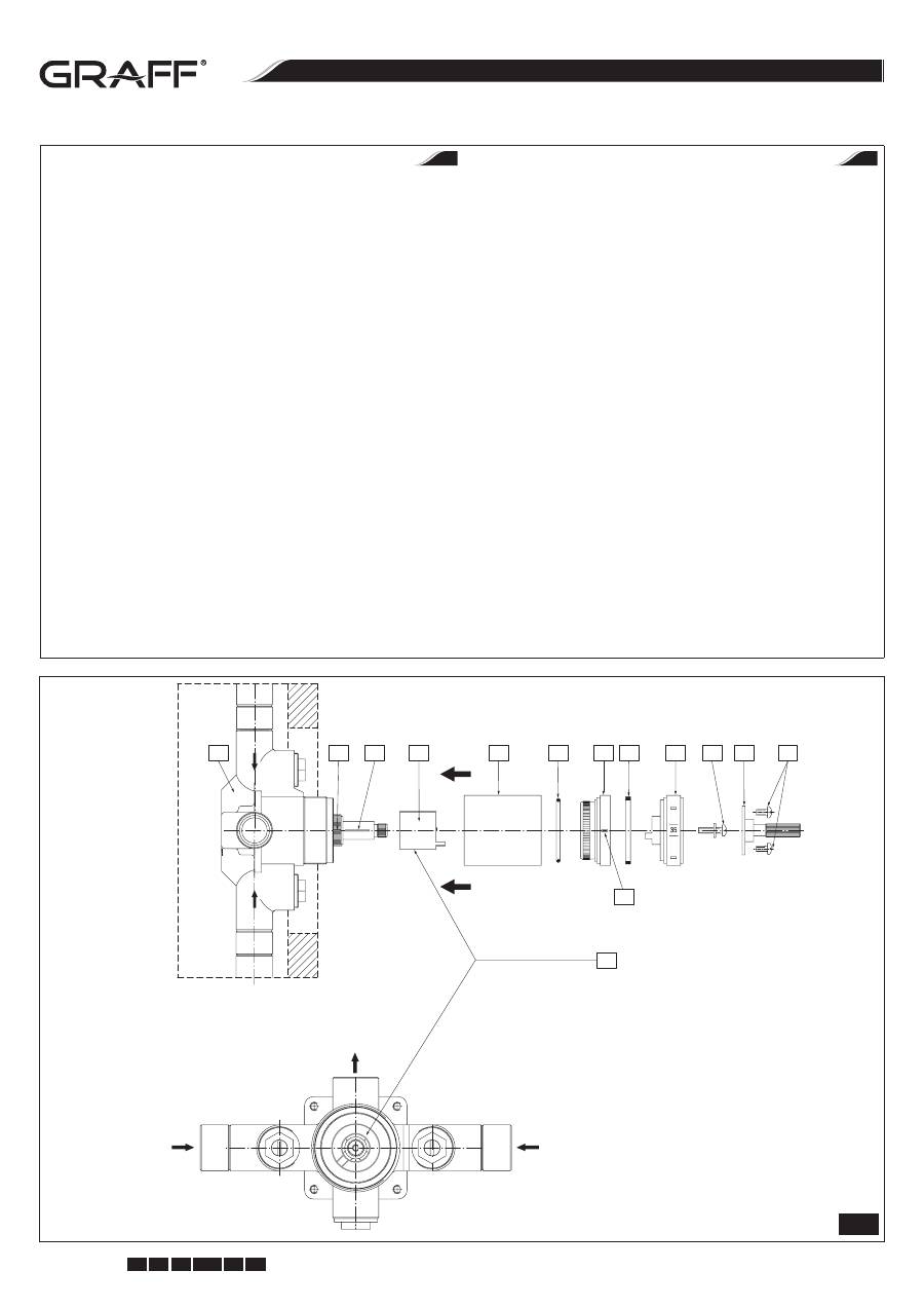
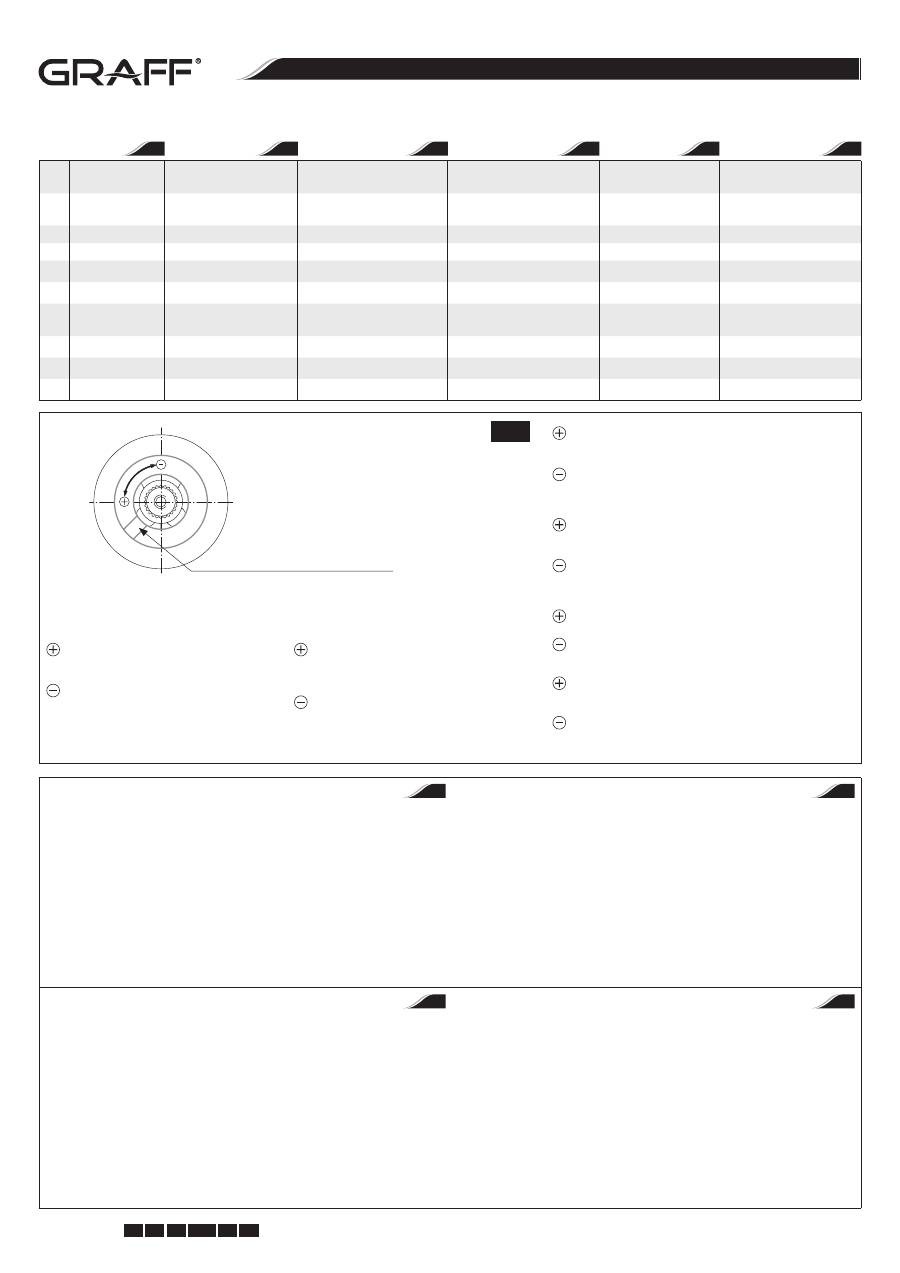
CALIBRATION OF TEMPERATURE SETTINGS
NOTE:
Do not turn the thermostatic mixing valve stem at this time. Turning the
mixing valve stem will change the factory calibration setting.
This valve has been calibrated at the factory to provide 38°C water when the
temperature scale reads 38 position. The maximum temperature limit stop
has been adjusted so the maximum water temperature will not exceed 49°C.
NOTE:
The listed water temperature settings are based upon the following
factory conditions:
- Hot and cold water pressure = 3 bar
- Hot water temperature = 65°C
- Cold water temperature = 15°C
If the actual water supply conditions differ significantly from those listed, you
may need to recalibrate the valve (see fig. 4.1):
•
Turn the water on for several minutes, then position a thermometer in the
water stream.
•
If the existing water supply conditions match the factory conditions, the
water temperature should be close to 38°C. If the water temperature is not
close to 38°C, remove and discard the plaster guard if it is still attached.
•
Remove the spline adapter
(T7)
which is attached to the temperature
scale dial
(T5)
with two short screws
(T8)
, then remove the screw
(T6)
that
attaches the dial and take out the dial
(T5)
.
•
Slowly rotate the thermostatic mixing valve stem
(L2)
until the water
temperature is a constant 38°C.
•
Do not turn the thermostatic mixing valve stem
(L2)
after you adjust the
temperature setting until you have installed the back all the components
of the valve.
•
Put back the temperature scale dial
(T5)
with the 38 mark aligned to the
black line on the indicator ring
(T3)
. Tighten the long screw
(T6)
and
replace the spline adapter tightening the two short screws
(T8)
.
KALIBRIERUNG DER EINSTELLUNGEN DER TEMPERATUR
ACHTUNG:
Die Spindel des thermostatischen Ventils in diesem Moment nicht
drehen. Das Drehen der Spindel des thermostatischen Ventils verursacht eine Än-
derung der Fabrikeinstellung.
Das Ventil wurde werkseitig eingestellt, um Wasser mit Temperatur von 38°C
bei der Einstellung der Temperaturskala in der Stellung 38°C zu liefern. Der
Begrenzer der Maximaltemperatur wurde so eingestellt, damit die Maximal-
temperatur des Wassers nicht 49° C überschreitet.
ACHTUNG:
Die angegebenen Temperatureinstellungen entsprechen den nach-
folgenden Fabrikbedingungen:
- Heiß- und Kaltwasserdruck = 3 bar
- Temperatur des Heißspeisewassers = 65°C
- Temperatur des Kaltspeisewassers = 15°C
Wenn die Einlaufparameter der Installation von den Parametern der Fabrik-
kalibrierung beträchtlich abweichen, kann eine erneute Kalibrierung
des Ventils nach seiner Montage nötig sein (siehe Zeich. 4.1)
•
Wasser für einige Minuten laufen lassen, und anschließend den Thermo-
meter im Wasserstrom anbringen.
•
Wenn die jetzigen Bedingungen des Speisewassers den Fabrikbedingun-
gen ähnlich sind, soll die Wassertemperatur 38°C betragen. Wenn die Was-
sertemperatur der Temperatur von 38°C nicht annährend ist, die Montage-
andeckung abnehmen, wenn diese montiert ist.
•
Den Keilwellenadapter
(T7)
, der an der Temperaturskala
(T5)
mit zwei kur-
zen Schrauben
(T8)
befestigt ist, abnehmen, anschließend die Schraube
(T6)
abschrauben, die die Skala befestigt, und die Skala
(T5)
abmontieren.
•
Langsam die Spindel des themostatischen Ventils
(L2)
bis zum Moment
der Stabilisierung der Wassertemperatur auf 38°C drehen.
•
Die Spindel des thermostatischen Ventils
(L2)
nach der Einstellung der
richtigen Temperatur bis zum Moment der erneuten Montage aller Ventil-
teile nicht umdrehen.
•
Die Temperaturskala
(T5)
mit der Marke 38°C in einer Linie mit der schwar-
zen Markierung
(T3)
auf der Hülse montieren. Die längere Schraube
(T6)
zudrehen und den Keilwellenadapter befestigen, indem zwei kürzere
Schrauben
(T8)
zugedreht werden.
CALIBRAGE DE REGLAGE DE LA TEMPERATURE
Attention:
A ce moment, il ne faut pas tourner la tige de la vanne thermostatique.
La rotation de la tige de la vanne thermostatique entrainera une modification des
réglages d’usine.
Cette vanne a été réglée en usine pour fournir de l’eau à une température de
38°C, lorsque l’échelle de température est sur la position «38». Le limiteur de
température maximale a été réglé de façon à ce que la température maximale
de l’eau ne dépasse pas 49°C.
Attention:
Le réglage de température est indique sur la base des paramètres
d’usine suivants:
- pression eau chaude et pression eau froide = 3 bars
- température de l’eau d’alimentation chaude = 65°C
- température de l’eau d’alimentation froide = 15°C
Si les paramètres d’entrée de l’installation différent significativement de ceux
indiqués ci-dessus, un nouveau calibrage de la vanne peut être nécessaire
(voir schéma 4.1):
•
Ouvrez l’eau pendant quelques minutes, puis positionnez le thermomètre
dans le jet d’eau.
•
Si les conditions d’alimentation en eau sont proches des réglages d’usine,
la température de l’eau devrait être de 38°C. Si la température de l’eau ne
s’approche pas de 38°C, retirez le cache de fixation s’il est toujours en place.
•
Retirez l’adaptateur cranté
(T7)
fixé à l’échelle de température
(T5)
par
deux vis courtes
(T8)
, puis dévissez la vis
(T6)
qui fixe l’échelle et enlevez
l’échelle
(T5)
.
•
Tournez lentement la tige de la vanne thermostatique
(L2)
jusqu’au mo-
ment où la température de l’eau se stabilise à 38°C.
•
Après avoir réglé la température exacte, ne tournez-pas la tige de la vanne
thermostatique avant d’avoir monté tous les éléments de la vanne.
•
Placez l’échelle de température
(T5)
avec le marquage «38°C» dans la
même ligne que le repère noir sur la douille
(T3)
. Serrez la vis longue
(T6)
et fixez l’adaptateur cranté, en serrant les deux vis courtes
(T8)
.
КАЛИБРОВКА ТЕМПЕРАТУРНЫХ НАСТРОЕК
ВНИМАНИЕ:
Не следует вращать шпинделем термоклапана в этот мо-
мент. Вращение шпинделем приведет к изменении производственных
установок.
Устройство настроено производителем для снабжения потребителей
водой температурой в 38°C при установке температурной шкалы на по-
зиции 38. ограничитель максимальной температуры настроен таким об-
разом, чтобы максимальная температура не превышала 49°C.
ВНИМАНИЕ:
следующие установки базируют на следующих, предвиден-
ных фабрикой, данных:
- давление горячей и холодной воды = 3 бара (0,3 MPa - мегапаскаля)
- температура входящей горячей воды = 65°C
- температура входящей холодной воды = 15°C
Если исходные условия слишком отличаются от предвиденных произво-
дителем, возможна необходимость вторичной настройки (калибровки)
клапана после его установки (см. рис. 4.1).
•
Включите воду на несколько минут, потом поместите градусник в струе
воды.
•
Если настоящие условия снабжения водой похожи на заводские, тем-
пература воды должна быть 38°C. Если температура воды не близка
38°C, снимите монтажную покрышку если она еще не снята.
•
Удалите адаптер шпинделя
(T7)
, который прикреплен к температурной
шкале
(T5)
двумя короткими винтами
(T8)
, потом открутите винт
(T6)
,
который фиксирует шкалу и снимите шкалу
(T5)
.
•
Медленно вращайте шпинделем термоклапана
(L2)
до момента стаби-
лизации температуры воды на 38°C.
•
После установки правильной температуры не крутите шпинделем тер-
моклапана
(L2)
пока все элементы устройства не будут опять смонти-
рованы вместе.
•
Наложите температурную шкалу
(T5)
с маркером 38°C в одной линии
со значком на втулке
(T3)
. Прикрутите винт подлиннее
(T6)
и зафикси-
руйте адаптер шпинделя прикручивая 2 винта покороче
(T8)
.
GB
D
RUS
F
c u t t i n g e d g e d e s i g n
Instructions for assembly and use • Montage- und Gebrauchsanweisung • Notice technique montage et utilisation • Инcтрукция по монтажу и обслуживанию • Instrucción de Montaje y Servicio • Manuale di Montaggio e Uso
8
IOG 2194.00
Rev. 2 May 2010
GB D
F RUS E
I
THERMOSTATISCHES MISCHVENTIL 1/2” UND 3/4” VANNE DE MÉLANGE THERMOSTATIQUE 1/2” ET 3/4” • ТЕРМОСТАТИЧЕСКИЙ СМЕШИВАЮЩИЙ КЛАПАН 1/2” И 3/4” LA VÁLVULA MEZCLADORA TERMOSTÁTICA 1/2” Y 3/4” • VALVOLA MISCELATRICE TERMOSTATICA 1/2” I 3/4” 1/2” AND 3/4” THERMOSTATIC MIXING VALVE
9
CALIBRACIÓN DE LOS AJUSTES DE TEMPERATURA
NOTA:
Esta vez no girar el la espiga de la válvula termostática mezcladora. Gi-
rando el la espiga de la válvula termostática cambiará la calibración hecha en
fábrica.
Esta válvula ha sido calibrada en la fábrica para suministrar el agua de 38°C
cuando la escala de temperatura indica la posición 38.
NOTA:
Las calibraciones de temperatura están basadas en las siguientes condi-
ciones de fábrica:
- Presión del agua caliente y fría = 3 bar
- Temperatura del agua caliente = 65°C
- Temperatura del agua fría = 15°C
Si las condiciones de alimentación del agua son significantemente diferen-
tes de las arriba citadas, es posible que usted tenga que recalibrar la válvula
(ver dis. 4.1):
•
Deje que el agua corra durante algunos minutos y luego meta un termó-
metro dentro del chorro del agua.
•
Si las condiciones de alimentación del agua son parecidas a las de la fabri-
ca, la temperatura del agua debe tener más o menos 38°C. Si la temperatu-
ra no llega o es considerablemente más alta de los 38°C, quite y elimine el
protector de yeso si todavía esta allí.
•
Quite el conector de polichaveta
(T7)
que esta colocado en el disco de la
escala de temperaturas
(T5)
por dos tornillos cortos
(T8)
, después quite el
tornillo
(T6)
que mantiene el disco y el disco mismo
(T5)
.
•
Gire despacio el la espiga de la válvula termostática
(L2)
mezcladora hasta
que la temperatura sea estable de 38°C.
•
No gire el la espiga de la válvula termostática
(L2)
al ajustar la temperatura
antes de reinstalar todos los componentes de la válvula.
•
Ponga de nuevo el disco de escala de temperatura
(T5)
con el número 38
en frente de la línea negra en el anillo indicador
(T3)
. Apretar el tornillo lar-
go
(T6)
y recolocar el conector de polichaveta apretando los dos tornillos
cortos
(T8)
.
CALIBRAZIONE DELL’IMPOSTAZIONE DELLA TEMPERATURA
ATTENZIONE:
Non si deve girare il fuso della valvola termostatica in questo mo-
mento. La rotazione del fuso della valvola termostatica modificherà l’impostazio-
ne della calibrazione di fabbrica.
Questa valvola è stata posizionata in fabbrica, in tal modo da fornire l’acqua
con la temperatura di 38°C. Il limitatore della temperatura massima è stato im-
postato in tal modo, che la temperatura massima dell’acqua non superi 49°C.
ATTENZIONE:
Le impostazioni della temperatura sono indicate in base alle se-
guenti condizioni di fabbrica:
- pressione dell’acqua calda e fredda = 3 bar
- temperatura dell’acqua calda di alimentazione = 65°C
- temperatura dell’acqua fredda di alimentazione = 15°C
Se i parametri in ingresso dell’impianto variano notevolmente rispetto ai so-
pra indicati, può verificarsi la necessità di un’ulteriore calibrazione della val-
vola (vedi fig. 4.1):
•
Lascia fluire l’acqua per qualche minuto, e di seguito metti il termometro
sotto il flusso dell’acqua.
•
Se le condizioni attuali dell’alimentazione di acqua assomigliano alle con-
dizioni di fabbrica, la temperatura dell’acqua dovrebbe essere di 38°C. Se la
temperatura dell’acqua non si avvicina ai 38°C, togli la protezione di mon-
taggio, se è ancora montata.
•
Togli l’adattatore della chiavetta
(T7)
il quale è fissato alla scala della tem-
peratura
(T5)
con due viti (T8), di seguito svita la vite
(T6)
, che fissa la scala
e togli la scala
(T5)
.
•
Ruota il fuso della valvola termostatica
(L2)
fino alla stabilizzazione della
temperatura dell’acqua sui 38°C.
•
Non ruotare il fuso della valvola termostatica dopo l’impostazione corretta
della temperatura, fino a quando non avrai montato nuovamente tutte le
parti della valvola.
•
Metti la scala della temperatura
(T5)
con la segnatura 38°C nella stessa li-
nea che la segnatura di color nero sulla boccola
(T3)
. Serra il bullone più
lungo
(T6)
e fissa l’adattatore della chiavetta, usando le due viti più corte
(T8)
.
L1
R1
L2
R2
T1
T2
M
R2
T3 T4
T5
T6
T7
T8
COLD
HO
T
I
E
4.1
Temperature Limiting Ring
Temperaturbegrenzer
Limiteur de température
Температурный ограничитель
Anillo Limitador de Temperature
Limitatore di temperatura
Shower head outlet
Ausgang für den Brausekopf (aus dem Ventil)
Sortie vers la tête de douche
Выход на душевую головку (душевой смеситель)
Salida al cabezal de la regadera
Entrata per la testa della doccia
Hot water inlet
Warmwasserversorgung
Alimentation d’eau chaude
Снабжение теплой водой
Entrada de agua caliente
Alimentazione con acqua calda
Cold water inlet
Kaltwasserversorgung
Alimentation d’eau froide
Снабжение холодной водой
Entrada de agua fría
Alimentazione con acqua fredda
8
c u t t i n g e d g e d e s i g n
Instructions for assembly and use • Montage- und Gebrauchsanweisung • Notice technique montage et utilisation • Инcтрукция по монтажу и обслуживанию • Instrucción de Montaje y Servicio • Manuale di Montaggio e Uso
9
IOG 2194.00
Rev. 2 May 2010
GB D
F RUS E
I
THERMOSTATISCHES MISCHVENTIL 1/2” UND 3/4” VANNE DE MÉLANGE THERMOSTATIQUE 1/2” ET 3/4” • ТЕРМОСТАТИЧЕСКИЙ СМЕШИВАЮЩИЙ КЛАПАН 1/2” И 3/4” LA VÁLVULA MEZCLADORA TERMOSTÁTICA 1/2” Y 3/4” • VALVOLA MISCELATRICE TERMOSTATICA 1/2” I 3/4” 1/2” AND 3/4” THERMOSTATIC MIXING VALVE
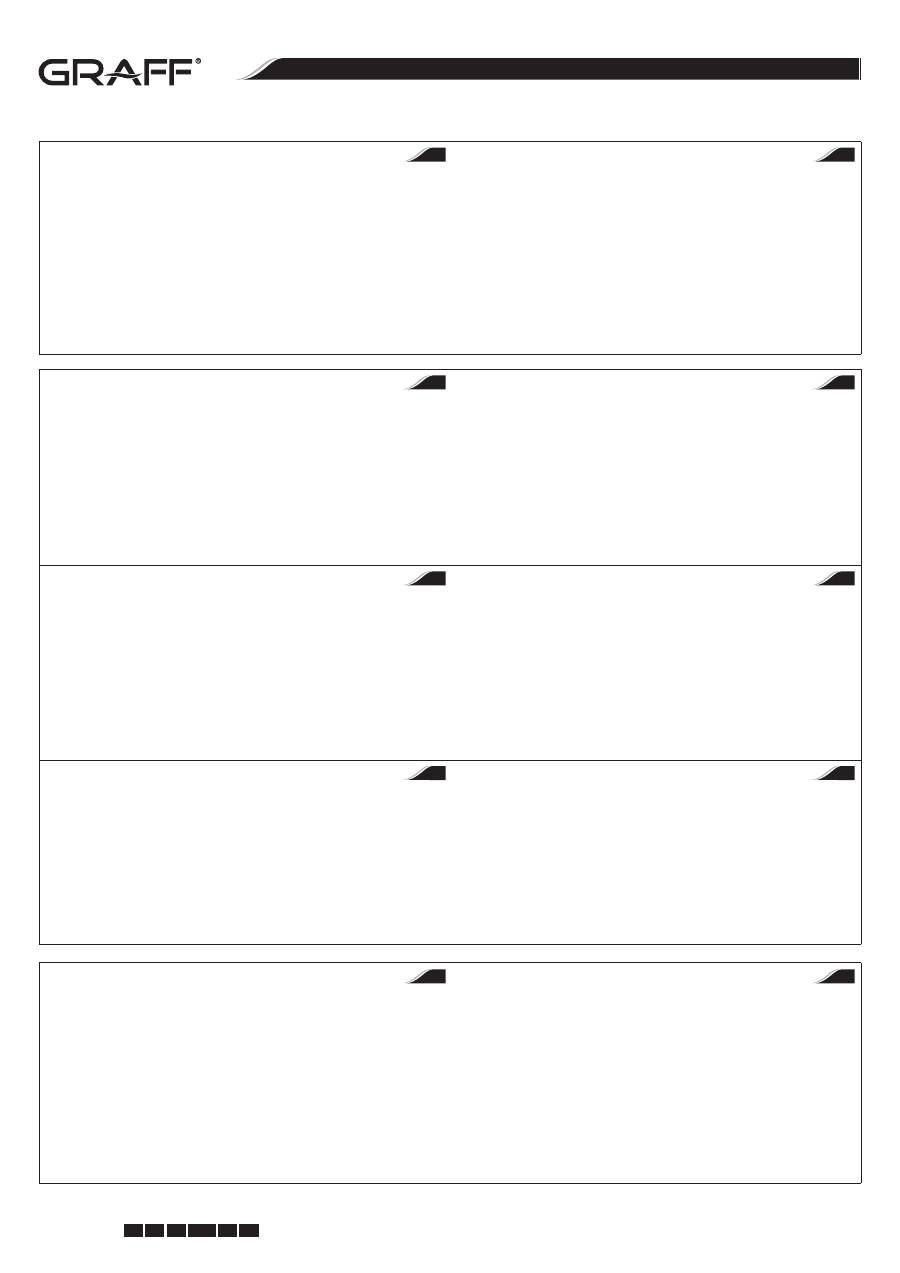
4.2
R1
Thermostatic valve
Thermostatischer
Mischventil
Vanne de mélange thermostatique
Термостатический
смесительный клапан
Válvula termostática
Valvola miscelatrice termostatica
R2
Temperature limiting
ring
Temperaturbegrenzer
Limiteur de température
Температурный ограничитель
Anillo limitadore temperatura Limitatore di temperatura
T1
Sleeve
Hülse
Douille
Втулка
Casquillo
Boccola
T2
O-ring seal
O-Ringdichtung
Joint torique
Сферическая прокладка (о-ринг)
Sellador de anillo
Guarnizione tipo o-ring
T3
Indicator ring
Hülse mit Anzeiger (Markierung) Douille avec indicateur (marqueur)
Втулка с маркером (обозначением) Anillo indicador
Boccola con indicatore (marcatura)
T4
Teflon slip ring
Teflongleitring
Rondelle de friction en Téflon
Тефлоновое скользящее кольцо
Anillo de corredera de teflon
Anello di usura di teflon
T5
Temperature scale dial Temperaturteilung
Echelle de température
Температурная шкала
Disco de la escala de
tempeturas
Scala di temperatura
T6
Screw with washer
Schraube mit Unterlegscheibe
Vis avec rondelle
Винт с подкладкой
Tornillo con arandela
Vite con rondella
T7
Spline adapter
Adapter der Keilwelle
Adaptateur cranté
Адаптер стержня
Conector de polichaveta
Adattatore della chiavetta
T8
Short screws (2 pieces) Kurze Schrauben (2 Stück)
Vis courtes (2 pièces)
Короткие винты (2 шт.)
Tornillos cortos (2 piezas)
Viti corte (2 pezzi)
GB
D
F
RUS
E
I
Correct position of the temperature limiting ring
Richtige Einstellung des Temperaturbegrenzers
Réglage correct du limiteur de température
Правильная настройка температурного ограничителя
La posición correcta del anillo limitador de temperatura
Impostazione corretta del limitatore di temperatura
Higher setting of maximum temperature – re-
move the temperature limiting ring from the
stem and rotate the ring counterclockwise.
Lower setting of maximum temperature – re-
move the temperature limiting ring from the
stem and rotate the ring clockwise.
Einstellung der höheren Maximaltemperatur – Tem-
peraturbegrenzer von der Keilwelle abnehmen (den
Dorn, die Spindeln) und den Begrenzer entgegen
der Uhrzeigerrichtung (nach links) drehen.
Einstellung der niedrigeren Maximaltemperatur –
Temperaturbegrenzer von der Keilwelle abnehmen
(den Dorn, die Spindeln) und den Begrenzer im
Sinne der Uhrzeigerrichtung (nach rechts) drehen.
Réglage d’une température maximale plus haute : retirez le limi-
teur de température de l’adaptateur cranté (tige) et tournez le
limiteur dans le sens antihoraire (à gauche)
Réglage d’une température maximale plus basse : retirez le limi-
teur de température de l’adaptateur cranté (tige) et tournez le
limiteur dans le sens horaire (à droite)
Увеличение крайней высокой температуры – снимите тем-
пературный ограничитель со стержня и поверните его в на-
правлении против часовой стрелке (на лево)
Снижение крайней высокой температуры – снимите темпе-
ратурный ограничитель со стержня и поверните его в на-
правлении согласно часовой стрелке (на право)
Temperatura máxima más alta – quite el anillo limitador de tem-
peratures del la espiga y gírelo el anillo hacia la izquierda
Temperatura máxima más baja– quite el anillo limitador de tem-
peratures del la espiga y gírelo el anillo hacia la derecha
Impostazione di temperatura più alta, massima – togli il limita-
tore di temperatura dalla chiavetta (stelo, fuso) e gira il limitato-
re in senso antiorario (a sinistra)
Impostazione di temperatura più bassa, massima – togli il limi-
tatore di temperatura dalla chiavetta (stelo, fuso) e gira il limita-
tore in senso orario (a destra)
THE VALVE OPERATION CHECK
1. Turn on the water again, and rotate the temperature scale dial fully clock-
wise. Then rotate the dial counterclockwise to the 38°C position.
2. Use a thermometer to determine the water temperature, which should be
about 38°C at this position.
3. After determining the water temperature at the 38°C position, turn the dial
counterclockwise to the second position (the maximum temperature limit
stop).
4. Use the thermometer to determine the water temperature at the second
position, which must not exceed 49°C. If the maximum temperature must
be adjusted, repeat the mixing valve calibration steps or see
„Maximum
Temperature Limit Adjustment”
section.
PRÜFUNG DER WIRKUNGSKORREKTHEIT DES VENTILS
1. Wasser erneut laufen lassen und den Knopf der Temperaturskala bis zum
Anschlag rechts umdrehen. Anschließend den Knopf links umdrehen und
auf Position 38°C einstellen.
2. Mit Thermometer die Temperatur des Auslaufswassers prüfen. Es soll zirka
38° C ind dieser Stellung sein.
3. Nach der Bestimmung der Wassertemperatur in der Stellung 38°, den
Knopf links bis zum Anschlag umdrehen (Maximaltemperaturbegrenzer).
4. Mit Thermometer die Temperatur des Auslaufswassers in der oberen Stel-
lung prüfen. Sie soll nicht 49°C überschreiten. Wenn die Einstellung der
Maximaltemperatur korrigiert werden soll, die Kalibrierung des Ventils
wiederholen oder den Abschnitt
„Regelung der Maximaltemperaturbegren-
zung”
durchlesen.
VERIFICATION DU FONCTIONNEMENT DE LA VANNE
1. Ouvrez à nouveau l’arrivée d’eau et tournez le sélecteur rotatif de l’échelle
de température à droite jusqu’au contact. Puis, tournez le sélecteur rotatif à
gauche et réglez-le sur la position 38°C.
2. A l’aide d’un thermomètre, vérifiez la température de l’eau à la sortie. Sur
cette position, elle doit être de 38°C environ.
3. Après avoir déterminé la température de l’eau sur la position 38°C, tour-
nez le sélecteur rotatif à gauche jusqu’au contact (limiteur de température
maximale).
4. A l’aide d’un thermomètre, vérifiez la température de l’eau à la sortie sur
la position maximale. Elle ne doit pas dépasser 49°C. S’il est nécessaire de
corriger le réglage de la température maximale, procédez à un nouveau
calibrage de la vanne ou référez-vous à la section
« Réglage de la limitation
de la température maximale »
.
ПРОВЕРКА ПРАВИЛЬНОЙ РАБОТЫ ПРИБОРА
1. Включите воду и поверните регулятор температуры до упора на право.
Потом поверните его на лево и поставьте на позиции 38°C.
2. Проверьте градусником температуру выходящей воды. Должно быть
ок. 38° C в этой позиции.
3. После определения температуры воды в позиции 38°, поверните во-
роток (регулятор) на лево, до упора (ограничитель максимальной тем-
пературы).
4. Проверьте градусником температуру выходящей воды в верхней по-
зиции. Она не должна превышать 49°C. Если установка максимальной
температуры должна быть откорректирована, повторите калибровку
клапана или прочитайте раздел
„Регулировка ограничения максималь-
ной температуры”
.
GB
D
RUS
F
c u t t i n g e d g e d e s i g n
Instructions for assembly and use • Montage- und Gebrauchsanweisung • Notice technique montage et utilisation • Инcтрукция по монтажу и обслуживанию • Instrucción de Montaje y Servicio • Manuale di Montaggio e Uso
10
IOG 2194.00
Rev. 2 May 2010
GB D
F RUS E
I
THERMOSTATISCHES MISCHVENTIL 1/2” UND 3/4” VANNE DE MÉLANGE THERMOSTATIQUE 1/2” ET 3/4” • ТЕРМОСТАТИЧЕСКИЙ СМЕШИВАЮЩИЙ КЛАПАН 1/2” И 3/4” LA VÁLVULA MEZCLADORA TERMOSTÁTICA 1/2” Y 3/4” • VALVOLA MISCELATRICE TERMOSTATICA 1/2” I 3/4” 1/2” AND 3/4” THERMOSTATIC MIXING VALVE
11
CONTROL DE OPERATIÓN DE LA VÁLVULA
1. Abra el agua de nuevo y gire el disco de escala de temperature completa-
mente hacia la derecha. Luego gire el disco hacia la dirección opuesta hasta
la posición de 38°C.
2. Use el termómetro para determinar la temperatura del agua que debe te-
ner ca. 38°C en esta posición.
3. Después de determinar la temperatura del agua en la posición de 38°C,
gire el disco hacia la izquierda para alcanzar la segunda posición (el limite
máximo de temperatura).
4. Use el termómetro para determinar la temperatura del agua en la segunda
posición; la temperatura no puede ser más alta de 49°C. Después de ajustar
la temperatura máxima, repetir los pasos de calibración de la válvula o ver
la secciona de
„Ajuste del Limite Máximo de Temperatura”
.
VERIFICAZIONE DEL CORRETTO FUNZIONAMENTO DELLA VALVOLA
1. Riapri l’acqua e gira la manopola della scala di temperatura fino alla resi-
stenza, a destra. Di seguito gira la manopola a sinistra e imposta sui 38°C.
2. Verifica con il termometro la temperatura dell’acqua in uscita. Dovrebbe
essere di circa 38°C in questa posizione.
3. Dopo aver impostato la temperatura dell’acqua in posizione 38°C, gira la
manopola a sinistra fino alla resistenza (limitatore di temperatura massi-
ma).
4. Verifica con il termometro la temperatura dell’acqua in uscita, in posizione
superiore. Essa non dovrebbe superare i 49°C. Se l’impostazione della tem-
peratura massima deve essere regolata, ripeti la calibrazione della valvola
vedi la sezione
„Regolazione della limitazione di temperatura massima”
.
I
E
MAXIMUM TEMPERATURE LIMIT ADJUSTMENT
If the maximum temperature limit needs to be adjusted do the following:
1. Remove the spline adapter
(T7)
which is attached to the temperature
scale dial
(T5)
with two short screws
(T8)
, then remove the screw that
(T6)
attaches the dial and take out the dial
(T5)
.
2. Remove the temperature limiting ring
(R2)
from the stem and rotate the
ring counterclockwise to set the higher temperature setting and clockwise
to decrease the setting - see fig. 4.2.
3. Put back the temperature limiting ring
(R2)
back onto the stem. Please
remember that the maximum temperature limit setting must not exceed
49°C.
REGELUNG DER MAXIMALTEMPERATURBEGRENZUNG
Wenn die Maximaltemperaturbegrenzung geregelt werden soll, folgender-
maßen vorgehen:
1. Den Keilwellenadapter
(T7)
, der an der Temperaturskala
(T5)
mit zwei
kurzen Schrauben
(T8)
befestigt ist, abmontieren und anschließend die
Schraube
(T6)
, die die Skala befestigt, abschrauben und die Skala
(T5)
ab-
montieren.
2. Den Begrenzer
(R2)
aus der Spindel herausnehmen und diese links umdre-
hen, um eine höhere Temperatur einzustellen, und rechts, um eine niedri-
gere Temperatur einzustellen, siehe Zeich. 4.2.
3. Den Begrenzer
(R2)
auf die Spindel aufsetzen, dabei beachten, dass die
Einstellung der Maximaltemperatur nicht 49°C überschreiten soll.
REGLAGE DE LA LIMITATION DE LA TEMPERATURE MAXIMALE
Si la limitation de la température maximale doit être réglée :
1. Retirez l'adaptateur cranté
(T7)
fixé à l'échelle de température
(T5)
par
deux vis courtes
(T8)
, puis deviser la vis
(T6)
qui fixe l'échelle et enlever
l'échelle
(T5)
.
2. Retirez le limiteur
(R2)
de la tige et tournez-le à gauche pour augmenter la
température et à droite afin de diminuer la température - voir schéma 4.2.
3. Mettez le limiteur sur la tige, sans oublier que le réglage de la limitation de
la température maximale ne peut pas dépasser 49°C.
РЕГУЛИРОВКА ОГРАНИЧЕНИЯ МАКСИМАЛЬНОЙ ТЕМПЕРАТУРЫ
Если настройка ограничения максимальной температуры нуждается
в регулировке, следует:
1. Снять адаптер шпинделя
(T7)
, который прикреплен к температурной
шкале
(T5)
двумя короткими винтами
(T8)
, потом открутить винт
(T6)
,
который фиксирует шкалу
(T5)
и снять ее.
2. Снять ограничитель
(R2)
со шпинделя и повернуть его на лево, чтобы
установить температуру повыше либо на право, чтобы ее снизить. См.
рис. 4.2.
3. Наденьте ограничитель
(R2)
на шпиндель, помня, что крайне высокая
температура не может превышать 49°C.
AJUSTE DEL LIMITE MÁXIMO DE TEMPERATURA
Si hay que ajustar el limite máximo de temperatura, haga lo siguiente:
1. Quite el conector de polichaveta
(T7)
que esta colocado en el disco de la
escala de temperaturas
(T5)
con dos tornillos cortos
(T8)
, después quite el
tornillo
(T6)
que mantiene el disco y el disco
(T5)
.
2. Quite el anillo limitador de temperaturas
(R2)
del la espiga y gírelo el anillo
hacia la izquierda para ajustar una temperatura mayor, y hacia la derecha
para ajustar una temperatura más baja - ver la dis. 4.2.
3. Ponga de nuevo el anillo limitador de temperaturas
(R2)
sobre el la espiga.
Recuerde, por favor, que la temperatura máxima no puede ser m’as alta de
49°C.
REGOLAZIONE DELLA LIMITAZIONE DI TEMPERATURA MASSIMA
Se l’impostazione della limitazione di temperatura massima richiede di essere
regolata, bisogna:
1. Togliere l’adattatore della chiavetta
(T7)
, il quale è fissato alla scala della
temperatura
(T5)
con due viti corte
(T8)
, di seguito svitare il bullone
(T6)
, il
quale fissa la scala e togliere la scala
(T5)
.
2. Togliere il limitatore
(R2)
dal fuso e girarlo a sinistra, per impostare una
temperatura più alta e a destra per abbassare la temperatura - vedi fig. 4.2.
3. Mettere il limitatore sul fuso, ricordandosi, che l’impostazione della
limitazione di temperatura massima non può superare i 49°C.
INSTALLATION OF THE DECORATIVE COVER AND LEVER
For the models with “traditional” cover:
See figs. 5.1, 5.2
1. Unscrew two bolts
(B)
and slide the installation cover
(A)
off the valve
body.
2. Make sure that the rubber gasket
(T9)
is inserted properly from the inside
of the decorative cover
(T10)
.
3. Slide the cover onto the valve, gently push it to the wall and screw with two
bolts
(T11)
.
4. Slide the valve cover
(T12)
onto the splines adapter
(T7)
.
5. Slide the lever
(T13)
onto the splines adapter
(T7)
. Secure the lever with
bolt
(T14)
using the included hex key.
MONTAGE DER ZIERBLENDE UND DES DREHKNOPFES
Für die Modelle mit der „herkömmlichen” Blende
Siehe Abb. 5.1, 5.2
1. Die beiden Schrauben
(B)
abschrauben und die Montageblende
(A)
vom
Ventilkörper abnehmen.
2. Es ist sicherzustellen, dass die Gummischeibe
(T9)
an der Innenseite der
Zierblende
(T10)
richtig positioniert ist.
3. Die Blende vorsichtig auf das Ventil aufschieben, vorsichtig an die Wand
heranrücken und mit zwei Schrauben
(T11)
anschrauben.
4. Die Ventilblende
(T12)
auf den Vielzahn-Adapter
(T7)
aufschieben.
5. Den Hebel
(T13)
auf den Vielzahn-Adapter
(T7)
aufschieben. Den Hebel
mittels der Schraube
(T14)
mit dem beiliegenden Innensechskantschlüssel
sichern.
GB
GB
D
D
RUS
F
I
E
10
c u t t i n g e d g e d e s i g n
Instructions for assembly and use • Montage- und Gebrauchsanweisung • Notice technique montage et utilisation • Инcтрукция по монтажу и обслуживанию • Instrucción de Montaje y Servicio • Manuale di Montaggio e Uso
11
IOG 2194.00
Rev. 2 May 2010
GB D
F RUS E
I
THERMOSTATISCHES MISCHVENTIL 1/2” UND 3/4” VANNE DE MÉLANGE THERMOSTATIQUE 1/2” ET 3/4” • ТЕРМОСТАТИЧЕСКИЙ СМЕШИВАЮЩИЙ КЛАПАН 1/2” И 3/4” LA VÁLVULA MEZCLADORA TERMOSTÁTICA 1/2” Y 3/4” • VALVOLA MISCELATRICE TERMOSTATICA 1/2” I 3/4” 1/2” AND 3/4” THERMOSTATIC MIXING VALVE
INSTALLATION OF THE DECORATIVE COVER AND LEVER
For the models with “modern” covers:
See figs. 5.1, 5.3
1. Unscrew two bolts
(B)
and slide the installation cover
(A)
off the valve
body.
2. Make sure that the o-ring seal
(T9)
is placed in the undercut in the
decorative cover
(T10)
.
3. Slide the cover onto the valve and gently slide it towards the wall. Set the
cover in the correct position. Slide the pressure ring
(T15)
onto the valve
and gently push it towards decorative cover
(T10)
. Turn it so the fixing
screw
(T15)
is facing down – tighten the screw
(T16)
using the supplied
hex key.
4. Slide the valve cover
(T12)
onto the splines adapter
(T7)
.
5. Slide the lever
(T13)
onto the splines adapter
(T7)
. Secure the lever with
bolt
(T14)
using the included hex key.
MONTAGE DER ZIERBLENDE UND DES DREHKNOPFES
Für die Modelle mit der „modernen” Blende
Siehe Abb. 5.1, 5.3
1. Die beiden Schrauben
(B)
abschrauben und die Montageblende
(A)
vom
Ventilkörper abnehmen.
2. Es ist sicherzustellen, dass sich die O-Ring-Dichtung
(T9)
im Schlitz der
Zierblende
(T10)
befindet.
3. Die Blende auf das Ventil aufschieben und vorsichtig an die Wand
heranrücken. Die Blende richtig positionieren. Den Druckring
(T15)
auf das
Ventil aufschieben und vorsichtig an die Zierblende
(T10)
heranrücken.
Der Druckring ist so zu drehen, dass die Sicherungsschraube
(T15)
nach unten zeigt - die Schraube
(T16)
ist dann mit dem beiliegenden
Innensechskantschlüssel festzudrehen.
4. Die Ventilblende
(T12)
auf den Vielzahn-Adapter
(T7)
aufschieben.
5. Den Hebel
(T13)
auf den Vielzahn-Adapter
(T7)
aufschieben. Den Hebel
mittels der Schraube
(T14)
mit dem beiliegenden Innensechskantschlüssel
sichern.
MONTAGE DE LA ROSACE ET DU SELECTEUR ROTATIF
Pour les modèles équipés du cache « traditionnel »:
Voir schéma 5.1, 5.2
1. Devisez les deux vis
(B)
et retirez le cache de fixation
(A)
du corps de vanne.
2. Assurez-vous que la rondelle caoutchouc
(T9)
est positionnée correctement
sur la face interne du cache décoratif
(T10)
.
3. Placez le cache sur la vanne, appuyez-le avec précaution contre le mur et
serrez-le à l'aide de deux vis
(T11)
.
4. Placez le cache de la vanne
(T12)
sur l'adaptateur cranté
(T7)
.
5. Placez le levier
(T13)
sur l'adaptateur cranté
(T7)
. Immobilisez le levier avec
une vis
(T14)
, à l'aide de la clé Allen jointe.
Pour les modèles équipés de caches «modernes»:
Voir schéma 5.1, 5.3
1. Devisez les deux vis
(B)
et retirez le cache de fixation
(A)
du corps de vanne.
2. Assurez-vous que le joint torique
(T9)
est situé dans la rainure du cache
décoratif
(T10)
.
3. Placez le cache sur la vanne et appuyez-le avec précaution contre le mur.
Placez le cache correctement. Présentez la bague de serrage
(T15)
sur la
vanne et positionnez-la avec précaution contre le cache décoratif
(T10)
.
Tournez-la de façon à ce que la vis de fixation
(T15)
soit dirigée vers le bas.
Serrez la vis
(T16)
à l'aide de la clé Allen jointe.
4. Placez le cache de la vanne
(T12)
sur l'adaptateur cranté
(T7)
.
5. Placez le levier
(T13)
sur l'adaptateur cranté
(T7)
. Immobilisez le levier avec
une vis
(T14)
, à l'aide de la clé Allen jointe.
МОНТАЖ ДЕКОРАТИВНОЙ ЗАЩИТЫ И РУЧКИ
Для моделей с «традиционной» защитой.
См. рис. 5.1, 5.2
1. Отвинти два винта
(B)
и сними монтажную защиту
(A)
с корпуса клапа-
на.
2. Убедись, что резиновая шайба
(T9)
уложена правильно по внутренней
стороне декоративной защиты
(T10)
.
3. Надвинь защиту на клапан, осторожно придвинь к стене и привинти
двумя винтами
(T11)
.
4. Надвинь защиту клапана
(T12)
на переходник шлицевого вала
(T7)
.
5. Надвинь рукоятку
(T13)
на переходник шлицевого вала
(T7)
. Заблоки-
руй рукоятку шурупом
(T14)
, используя приложенный имбусный клю-
чик.
Для моделей с «современными» защитами.
См. рис. 5.1, 5,3
1. Отвинти два винта
(B)
и сними монтажную защиту
(A)
с корпуса клапа-
на.
2. Убедись, что прокладка типа o-ринг
(T9)
находится в вырезе декора-
тивной защиты
(T10)
.
3. Надвинь защиту на клапан и осторожно придвинь к стене. Установи за-
щиту в правильном положении. Надвинь прижимное кольцо
(T15)
на
клапан и осторожно придвинь его к декоративной защите
(T10)
. По-
верни его так, чтобы блокирующий винт
(T15)
был направлен вниз - за-
тяни винт
(T16)
при помощи приложенного имбусного ключика.
4. Надвинь защиту клапана
(T12)
на переходник шлицевого вала
(T7)
.
5. Надвинь рукоятку
(T13)
на переходник шлицевого вала
(T7)
. Заблоки-
руй рукоятку шурупом
(T14)
, используя приложенный имбусный клю-
чик.
INSTALACIÓN DE LA TAPA DECORATIVA Y DEL MANDO
Para los modelos con la tapa “tradicional”:
Ver las figs. 5.1, 5.2
1. Desenrosque dos tornillos
(B)
y quite la tapa de montaje
(A)
del cuerpo de
la válvula.
2. Asegúrese de que la arandela de goma
(T9)
está bien posicionada por el
lado interior de la tapa decorativa
(T10)
.
3. Meta la tapa en la válvula y, con cuidado, acérquela a la pared y atorníllela
con dos tornillos
(T11)
.
4. Meta la tapa de la válvula
(T12)
en el adaptador de la multichaveta
(T7)
.
5. Meta la manilla
(T13)
en el adaptador de la multichaveta
(T7)
. Asegure la
manilla con el tornillo
(T14)
usando la llave allén adjunta.
Para los modelos con la tapa “moderna”:
Ver las fig. 5.1, 5.3
1. Desenrosque dos tornillos
(B)
y quite la tapa de montaje
(A)
del cuerpo de
la válvula.
2. Asegúrese de que la junta tórica
(T9)
está en el recorte en la tapa decorati-
va
(T10)
.
3. Meta la tapa en la válvula y, con cuidado, acérquela a la pared. Coloque la
tapa en la posición adecuada. Meta el anillo de apriete
(T15)
en la válvula
y, con cuidado, acérquelo a la tapa decorativa
(T10)
. Gírelo del modo que el
tornillo de protección
(T15)
esté orientado para abajo – apriete el tornillo
(T16)
usando la llave allén adjunta.
4. Meta la tapa de la válvula
(T12)
en el adaptador de la multichaveta
(T7)
.
5. Meta la manilla
(T13)
en el adaptador de la multichaveta
(T7)
. Asegure la
manilla con el tornillo
(T14)
usando la llave allén adjunta.
MONTAGGIO DEL ROSONE E DELLA MANOPOLA
Per modelli con la protezione „tradizionale”:
Vedi fig. 5.1, 5.2
1. Svita le due viti
(B)
e sfila la protezione di montaggio
(A)
dal corpo della
valvola.
2. Accertati, che la rondella di gomma
(T9)
sia in posizione corretta dalla par-
te interna della protezione decorativa
(T10)
.
3. Infila la protezione sulla valvola, facendo attenzione spingi contro la parete
e avvita con due bulloni
(T11)
.
4. Infila la protezione della valvola
(T12)
sull’adattatore della chiavetta
(T7)
.
5. Infila la leva
(T13)
sull’adattatore della chiavetta
(T7)
. Fissa la leva con la
vite
(T14)
, usando la chiave a brugola in dotazione.
Per modelli con protezioni „moderne”:
Vedi fig. 5.1, 5.3
1. Svita le due viti
(B)
e sfila la protezione di montaggio
(A)
dal corpo della
valvola.
2. Accertati che la guarnizione tipo o-ring
(T9)
si trovi nell’intaglio della pro-
tezione decorativa
(T10)
.
3. Infila la protezione sulla valvola e facendo attenzione spingila contro la pa-
rete. Disponi la protezione in posizione corretta. Infila l’anello di pressione
(T15)
sulla valvola e facendo attenzione spingilo contro la protezione de-
corativa
(T10)
. Girala in tal modo, da direzionare la vite di fissaggio
(T15)
in
basso – serra la vite
(T16)
usando la chiave a brugola in dotazione.
4. Infila la protezione della valvola
(T12)
sull’adattatore della chiavetta
(T7)
.
5. Infila la leva
(T13)
sull’adattatore della chiavetta
(T7)
. fissa la leva con la vite
(T14)
, usando la chiave a brugola in dotazione.
GB
D
RUS
F
I
E
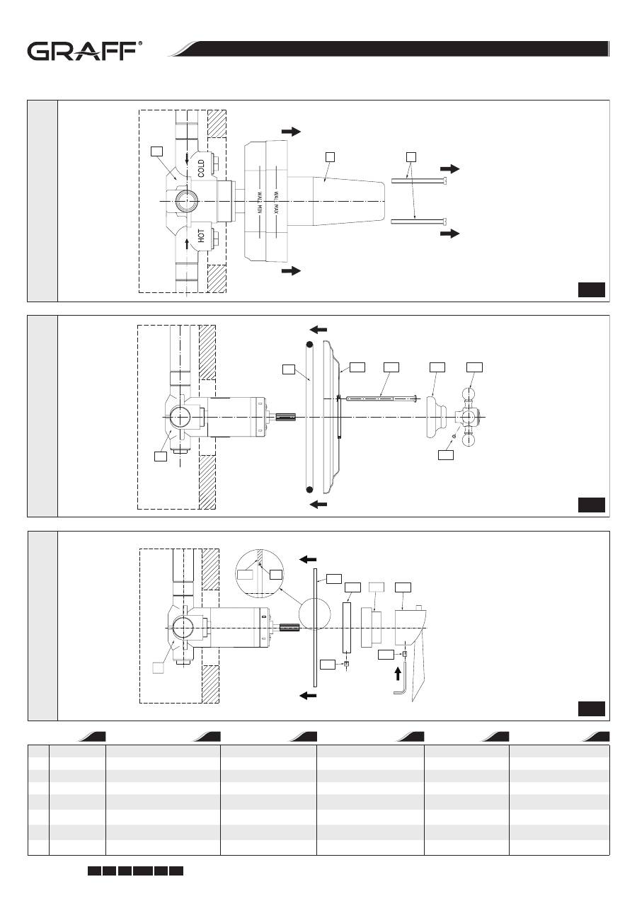
c u t t i n g e d g e d e s i g n
Instructions for assembly and use • Montage- und Gebrauchsanweisung • Notice technique montage et utilisation • Инcтрукция по монтажу и обслуживанию • Instrucción de Montaje y Servicio • Manuale di Montaggio e Uso
12
IOG 2194.00
Rev. 2 May 2010
GB D
F RUS E
I
THERMOSTATISCHES MISCHVENTIL 1/2” UND 3/4” VANNE DE MÉLANGE THERMOSTATIQUE 1/2” ET 3/4” • ТЕРМОСТАТИЧЕСКИЙ СМЕШИВАЮЩИЙ КЛАПАН 1/2” И 3/4” LA VÁLVULA MEZCLADORA TERMOSTÁTICA 1/2” Y 3/4” • VALVOLA MISCELATRICE TERMOSTATICA 1/2” I 3/4” 1/2” AND 3/4” THERMOSTATIC MIXING VALVE
13
A
B
R1
Top vie
w • A
nsich
t v
on oben •
Vue de dessus
Вид свер
ху •
Vista delan
ter
a •
Vista dall
’alt
o
T9
R1
T10
T11
T12
T14
T13
Side vie
w • S
eit
enansich
t •
Vue de c
ôt
é
Бок
овой вид •
Vista la
ter
al •
Vista dal la
to
T9
Sealing
Dichtung (Gummiunterlegscheibe)
Joint (rondelle caoutchouc)
Уплотнение (резиновая подкладка) Sellador
Guarnizione (rondella di gomma)
T10
Plate
Dekorativer Schutz
Cache décoratif
Украсительная розетка
Cubierta
Protezione decorativa
T11
Screw (2 pieces)
Schrauben (2 Stück)
Vis (2 pièces)
Винты (2 шт.)
Tornillo (2 piezás)
Viti ( 2 pezzi)
T12
Valve cover
Schutz des Ventils
Cache de vanne
Прикрытие клапана
Cubierta de la válvula
Protezione della valvola
T13
Handle
Drehknopf (Hebel)
Sélecteur rotatif (levier)
Рычаг
Manilla
Manopola (leva)
T14
Handle screw
Schraube des Drehknopfes (des Hebels)
Vis du sélecteur rotatif (levier)
Винт рычага
Tornillo de la manilla
Vite della manopola (leva)
T15
Pressure ring
Druckring
Bague de serrage
Прижимное колцо
Anillo de apriete
Anello di pressione
T16
Screw
Schraube
Vis
Винт
Tornillo
Vite
GB
D
F
RUS
E
I
5.1 5.2
R1
T10
T12
T15
T13
T14
T10
T9
T16
5.3
Side vie
w • S
eit
enansich
t •
Vue de c
ôt
é
Бок
овой вид •
Vista la
ter
al •
Vista dal la
to

12
c u t t i n g e d g e d e s i g n
Instructions for assembly and use • Montage- und Gebrauchsanweisung • Notice technique montage et utilisation • Инcтрукция по монтажу и обслуживанию • Instrucción de Montaje y Servicio • Manuale di Montaggio e Uso
13
IOG 2194.00
Rev. 2 May 2010
GB D
F RUS E
I
THERMOSTATISCHES MISCHVENTIL 1/2” UND 3/4” VANNE DE MÉLANGE THERMOSTATIQUE 1/2” ET 3/4” • ТЕРМОСТАТИЧЕСКИЙ СМЕШИВАЮЩИЙ КЛАПАН 1/2” И 3/4” LA VÁLVULA MEZCLADORA TERMOSTÁTICA 1/2” Y 3/4” • VALVOLA MISCELATRICE TERMOSTATICA 1/2” I 3/4” 1/2” AND 3/4” THERMOSTATIC MIXING VALVE
MAINTENANCE
•
Clean water guarantees that a mixer equipped with ceramic flow regula-
tors will work correctly, i.e. the water should not contain any impurities
such as sand, boiler scale etc. Because of this, the pipe system should be
equipped with sieve filters or, if there is no such possibility, with individual
cut-off valves with filters designed for such units.
•
In the event of increased steering resistance, greater pressure should not
be exerted on the handle, as this may cause damage to the flow regulator.
In such a situation, the regulator should be removed and cleaned of the dirt
and impurities which have accumulated on it.
•
The seals should be maintained with vaseline or silicon oil.
Cleaning the outer coating:
•
dirt or stains on the external surfaces of the mixer resulting from scale
deposits should be removed by washing the unit with soapy water only.
Scale deposits should be dissolved with vinegar then the surface rinsed
with clean water and rubbed dry with a soft cloth,
•
under no circumstances should the surface of the mixer be cleaned with
coarse cloths or cleaning agents containing abrasive materials or acids,
•
plastic or lacquered parts must not be cleaned with chemicals containing
alcohol, disinfectants or solvents.
WARTUNG
•
Eine Garantie für richtige Funktion von Batterien mit keramischen
Durchflussregler ist sauberes Wasser, dass heißt Wasser ohne solche Verun-
reinigungen, wie: Sand, Kesselstein, usw. Deswegen wird die Ausrüstung
der Wasserleitungsanlage mit Gitterfilter gefordert, und wenn solche Filter
nicht vorhanden sind, soll es möglich sein, die für Batterien bestimmte Ab-
sperrventile mit Filter zu montieren.
•
Bei vergrößertem Einstellungswiderstand soll man auf den Heben keinen
größeren Druck ausüben, da es eine Beschädigung des Durchflussreglers
verursachen kann. Wenn es so ist, soll man den Regler ausmontieren und
die auf dem Regler gesammelten Verunreinigungen entfernen.
•
Die Dichtungen sollen mit Vaselin oder Silikonöl gewartet werden.
Reinigung der äußeren Oberflächen:
•
Den Schmutz oder die Flecke, entstanden infolge von Steinablagerungen
auf den äußeren Batterieoberflächen, durch Abspülen mit Seifewasser
entfernen, den Stein mit Essig lösen, danach die Oberfläche mit sauberem
Wasser abspülen und mit weichem Lappen trocknen.
•
Auf keinem Fall die Batterieoberfläche mit rauen Lappen oder mit scheuer-
mittel- oder säurehaltigen Reinigungsmitteln reinigen
•
Für die Reinigung der Kunststoffteile oder lackierten Teile kann man keine
alkoholhaltige Mitteln, Desinfektions- oder Lösungsmitteln verwenden.
ENTRETIEN
•
La garantie du fonctionnement correct de la robinetterie équipée en ré-
gulateurs de flux céramiques est l’eau propre, c’est-à-dire une eau qui ne
contient pas de polluants tels que : sable, tartre, etc. Pour cette raison, il
est exigé d’équiper les installations d’eau en crépines et, en cas d’absence
d’une telle possibilité, en vannes d’arrêt individuelles avec un filtre destiné
à la robinetterie.
•
En cas de résistance accrue de la commande, il est interdit d’exercer un plus
grand appui sur le levier car cela peut provoquer l’endommagement du
régulateur de flux. Dans ce cas, il faut démonter le régulateur et enlever les
polluants qui s’y sont rassemblés.
•
Entretenir les joints d’étanchéité avec de la vaseline ou de l’huile de mo-
teur.
Nettoyage des couches externes:
•
éliminer les salissures ou les taches apparues suite au dépôt du tartre sur
les surfaces externes de la robinetterie en la lavant uniquement avec de
l’eau et du savon ; pour dissoudre le tartre, utiliser du vinaigre, rincer en-
suite la surface avec de l’eau propre et essuyer avec un chiffon sec et doux,
•
en aucun cas, il ne faut nettoyer la surface de la robinetterie avec des chif-
fons rugueux ou des produits de nettoyage contenant des matériaux abra-
sifs et des acides,
•
il est interdit d’utiliser, pour le nettoyage des parties réalisées en matière
plastique et vernies, des produits contenant de l’alcool, des substances de
désinfection ou des dissolvants.
КОНСЕРВИРОВАНИЕ
•
Гарантией правильной работы смесителей, оснащенных керамиче-
скими регуляторами протекания, является чистая вода, т.е. которая не
содержит таких загрязнений, как : песок, накипь, и т.п. В связи с выше-
сказанным, требуется оснащение водопроводной системы сетчатыми
фильтрами, а если это невозможно, индивидуальными запорными кла-
панами с фильтром, предназначенными для смесителей.
•
В случае повышенного сопротивления при регулировании запре-
щается увеличивать силу нажима на рычаг т.к. это может привести к
повреждению регулятора протекания. В этой ситуации необходимо
демонтировать регулятор и очистить его от загрязнений.
•
Уплотнения консервировать вазелином или силиконовым маслом.
Очистка наружных поверхностей:
•
загрязнение или пятна, возникшие в результате оседания камня на
внешних поверхностях смесителя, смывать исключительно водой с
мылом, для растворения камня применять уксус, затем промыть по-
верхность чистой водой и досуха вытереть мягкой тряпочкой,
•
ни в каком случае нельзя чистить поверхность смесителя шерохова-
тыми тряпочками или чистящими средствами с содержанием абразив-
ных компонентов и кислот,
•
для чистки элементов, выполненных из пластмассы или лакированных,
запрещается использовать средства, содержащие алкоголь, дезинфи-
цирующие средства или растворители.
CONSERVACIÓN
•
Para el buen funcionamiento de las baterías equipadas en reguladores ce-
rámicos del flujo es necesaria el agua limpia, que quiere decir el agua sin
tales basuras como la arena, la piedra de caldera etc. Por eso es imprescin-
dible equipar la instalación de cañerías en filtros de tela metálica, y en caso
de la falta de tales posibilidades, en válvulas particulares cortadoras con el
filtro adecuadas para la batería.
•
En caso de una resistencia aumentada del mando no se puede ejercer una
presión mayor en la palanca porque esto puede provocar una avería del
regulador de flujo. En este caso hay que desmontar el regulador y quitar
toda la basura agrupada.
•
Conservar las empaquetaduras con la vaselina o el aceite de silicona.
Limpieza de las superficies exteriores:
•
la suciedad o las manchas que se produjeron a causa de depositar el sarro
en las superficies exteriores de la batería hay que quitarlas lavando la ba-
tería sólo con el agua y el jabón, para diluir el sarro use vinagre, después
enjuague la superficie con el agua limpia y séquela con un trapo suave,
•
en cualquier caso no se puede limpiar la superficie de la batería con trapos
ásperos o medios de limpieza que contienen abrasivos y ácidos,
•
para limpiar las partes hechas de materias plásticas y barnizadas no se pue-
de usar medios que contienen alcohol, sustancias desinfectante o disol-
ventes.
MANUTENZIONE
•
La garanzia per un funzionamento corretto delle batterie equipaggiati in
regolatori ceramici di portata è l’acqua pulita, ossia priva di tali elementi,
come: sabbia, incrostazione ecc. In relazione a quanto suddetto si è tenuti
a equipaggiare l’impianto idrico in filtri a rete, nel caso in cui fosse impossi-
bile, in individuali valvole di arresto con un filtro predisposto per la batteria.
•
Nel caso in cui la resistenza di commando aumenti, non è ammesso di eser-
citare una pressione maggiore sulla leva, in quanto si può danneggiare il
regolatore della portata. In tal caso bisogna smontare il regolatore ed eli-
minare le impurità in esso accumulate.
•
Per la manutenzione delle guarnizioni usare vaselina od olio di silicone.
Pulizia di rivestimenti esterni:
•
Eliminare lo sporco o le macchie, formatesi in conseguenza alla sedimen-
tazione del calcare sulle superfici esterne della batteria, lavando la batteria
esclusivamente con acqua e sapone, per lo scioglimento del calcare usare
l’aceto, in seguito sciacquare la superficie con acqua pulita ed asciugare
perfettamente con un panno morbido ed asciutto.
•
Non è ammessa in alcun caso la pulizia della superficie della batteria con
panni scabrosi o detergenti di pulizia che contengono sostanze abrasive
e acidi.
•
Per la pulizia delle parti eseguite di materie plastiche e verniciate non è am-
messo l’uso di detergenti, che contengono alcol, sostanze disinfettanti
o solventi.
I
E
GB
D
RUS
F
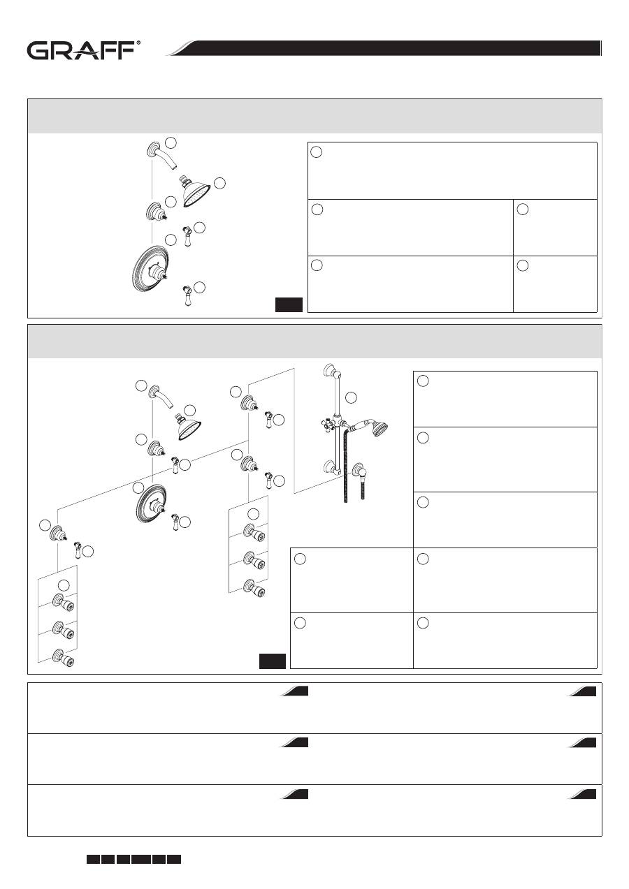
c u t t i n g e d g e d e s i g n
Instructions for assembly and use • Montage- und Gebrauchsanweisung • Notice technique montage et utilisation • Инcтрукция по монтажу и обслуживанию • Instrucción de Montaje y Servicio • Manuale di Montaggio e Uso
14
IOG 2194.00
Rev. 2 May 2010
GB D
F RUS E
I
THERMOSTATISCHES MISCHVENTIL 1/2” UND 3/4” VANNE DE MÉLANGE THERMOSTATIQUE 1/2” ET 3/4” • ТЕРМОСТАТИЧЕСКИЙ СМЕШИВАЮЩИЙ КЛАПАН 1/2” И 3/4” LA VÁLVULA MEZCLADORA TERMOSTÁTICA 1/2” Y 3/4” • VALVOLA MISCELATRICE TERMOSTATICA 1/2” I 3/4” 1/2” AND 3/4” THERMOSTATIC MIXING VALVE
GUARANTEE:
The guarantee conditions are contained on a separate sheet.
IN THE EVENT OF A PROBLEM:
e-mail: graff@graff-mixers.com
GARANTIE:
Die Gewährleistungsbedingungen sind auf dem separaten Blatt.
SOLLTEN PROBLEME AUFTRETEN wenden Sie sich an uns
e-mail: graff@graff-mixers.com
GARANTIE:
Les conditions de garantie se trouvent dans une feuille séparée.
EN CAS DE PROBLEME:
e-mail: graff@graff-mixers.com
ГАРАНТИЯ:
Гарантийные условия на отдельном листе.
ЕСЛИ ВОЗНИКНЕТ ПРОБЛЕМА:
e-mail: graff@graff-mixers.com
GARANTÍA:
Las condiciones de la garantía se encuentran en otra hoja
EN CASO DE PROBLEMAS:
e-mail: graff@graff-mixers.com
GARANZIA:
Le condizioni di garanzia sono indicate sul foglio separato.
NEL CASO IN CUI SI VERIFICHINO PROBLEMI:
e-mail: graff@graff-mixers.com
F
RUS
E
I
D
GB
3/4” Thermostatic Valve with Trim Kit
Termostatventil 3/4” mit Schutzabdeckung
Vanne thermostatique 3/4” avec cache
Термостатический клапан 3/4” дюйка с накладкой
Válvula termostática 3/4” con el juego decorativo
Valvola termostatica 3/4” con la protezione
1/2” Stop/Volume Control Valve
Absperrventil 1/2”
Vanne d’arrêt 1/2”
Отоекатель 1/2 дюйка
(выключающий клапан 1/2 дюйка)
Válvula reguladora de cierre 1/2”
Valvola di arresto 1/2”
Shower Arm
Arm des Brausekopfes
Bras de tête de douche
Базисная трубка душа
Codo de la ducha
Braccio della testa della doccia
Shower Head
Brausekopf
Tête de douche
Душевая головка
Cabeza de la ducha
Testa della doccia
Hand-Held Shower with Wall-Mount Slide Bar
Brausesatz mit verstellbaren Griff
Kit de douche avec support coulissant
Душевой комплект с передвижим держателем
Ducha sostenidos con la mano desplazable
montada en la pared
Gruppo doccia con attacco spostabile
Body Spray
Seitliche Brausedüse
Tuyère latérale
Жиклеп боковой (Боди Спрей)
Rociador corporal
Getto laterale
Handle
Griff
Support
Держатель
Manecilla
Attacco
G
A
B
C
D
E
F
Custom shower configuration for 1/2” thermostatic valve
•
Beispiel des thermostatischen Installationssatzes 1/2”
Exemple de l’installation du thermostat 1/2”
•
Пример инсталляци термостатического комплекта 1/2” дюйка
Configuración ejemplar de ducha para la válvula termostática 1/2”
•
Esempio di installazione del termostatico 1/2”
Custom shower configuration for 3/4” thermostatic valve
•
Beispiel des thermostatischen Installationssatzes 3/4”
Exemple de l’installation du thermostat 3/4”
•
Пример инсталляци термостатического комплекта 3/4” дюйка
Configuración ejemplar de ducha para la válvula termostática 3/4”
•
Esempio di installazione del termostatico 3/4”
G
A
B
C
D
G
G
A
B
C
D
G
G
B
B
F
E
E
B
G
G
1/2” Thermostatic Valve with Trim Kit
Termostatventil 1/2” mit Schutzabdeckung
Vanne thermostatique 1/2” avec cache
Термостатический клапан 1/2” дюйка с накладкой
Válvula termostática 1/2” con el juego decorativo
Valvola termostatica 1/2” con la protezione
1/2” Stop/Volume Control Valve
Absperrventil 1/2”
Vanne d’arrêt 1/2”
Отоекатель 1/2 дюйка (выключающий клапан 1/2 дюйка)
Válvula reguladora de cierre 1/2”
Valvola di arresto 1/2”
Shower Head
Brausekopf
Tête de douche
Душевая головка
Cabeza de la ducha
Testa della doccia
Shower Arm
Arm des Brausekopfes
Bras de tête de douche
Базисная трубка душа
Codo de la ducha
Braccio della testa della doccia
Handle
Griff
Support
Держатель
Manecilla
Attacco
A
B
C
D
G
