Ridgid micro CA-300: instruction
Class: Power tools
Type:
Manual for Ridgid micro CA-300

micro
CA-300
EN
p. 1
FR
p. 21
ES
p. 41
DE
p. 63
NL
p. 85
IT
p. 107
PT
p. 129
SV
p. 151
DA
p. 171
NO
p. 191
FI
p. 211
PL
p. 231
CZ
p. 253
SK
p. 273
RO
p. 293
HU
p. 315
EL
p. 337
HR
p. 361
SL
p. 381
SR
p. 401
RU
p. 423
TR
p. 447
RIDGE TOOL COMPANY

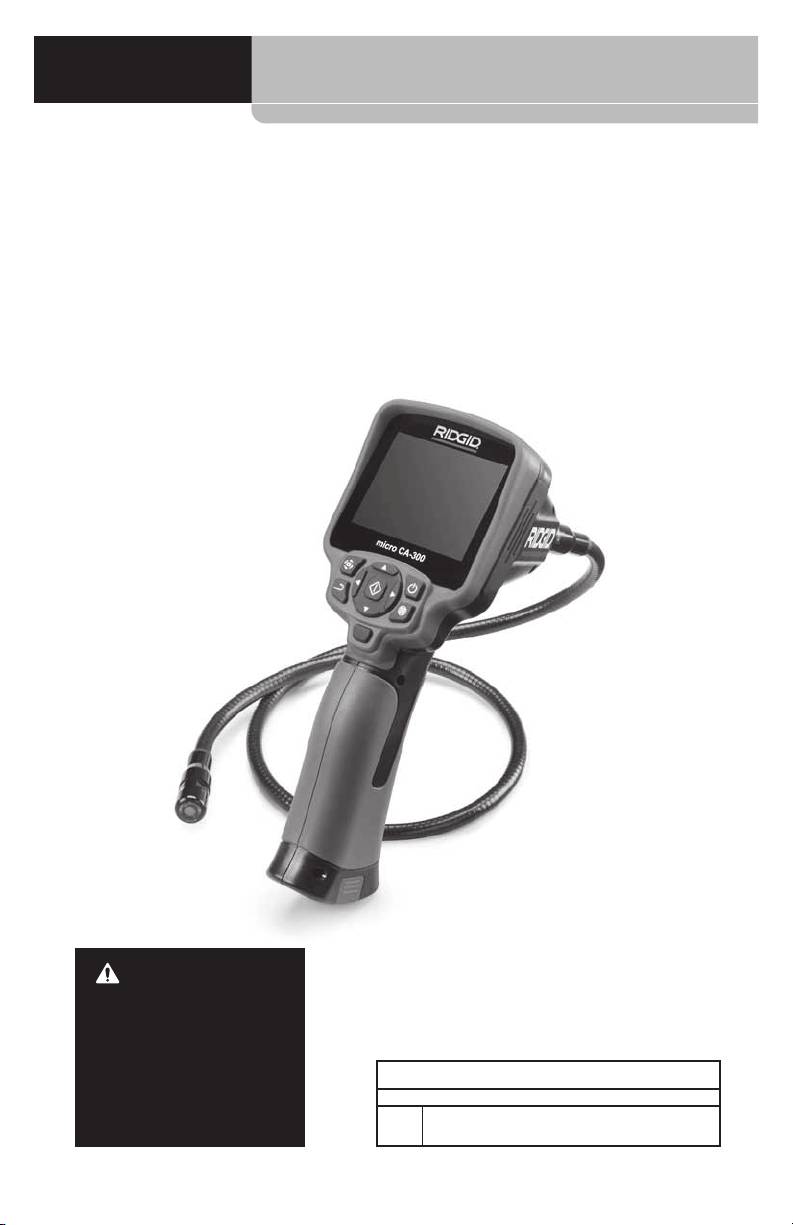
micro CA-300
micro CA-300
Inspection Camera
WARNING!
Read this Operator’s Man-
ual carefully before using
this tool. Failure to under-
stand and follow the con-
tents of this manual may
micro CA-300 Inspection Camera
result in electrical shock,
Record Serial Number below and retain product serial number which is located on nameplate.
re and/or serious per-
Serial
sonal injury.
No.

micro CA-300 Inspection Camera
C ontents
Safety Symbols .................................................................................................................................................3
General Safety Information.......................................................................................................................3
Work Area Safety ...........................................................................................................................................3
Electrical Safety .............................................................................................................................................3
Personal Safety ..............................................................................................................................................3
Equipment Use and Care ........................................................................................................................... 4
Service ............................................................................................................................................................... 4
Specic Safety Information ....................................................................................................................... 4
micro CA‑300 Inspection Camera Safety ............................................................................................4
Description, Specications and Standard Equipment ...............................................................5
Description ......................................................................................................................................................5
Specications ................................................................................................................................................. 5
Standard Equipment ................................................................................................................................... 6
Controls ............................................................................................................................................................6
FCC Statement .................................................................................................................................................. 6
Electromagnetic Compatibility (EMC) .................................................................................................7
Icons .......................................................................................................................................................................7
Tool Assembly ................................................................................................................................................... 7
Changing/Installing Batteries .................................................................................................................. 7
Powering with the AC Adapter .............................................................................................................. 8
Installing the Imager Head Cable or Extension Cables ................................................................ 8
Installing Accessories ..................................................................................................................................8
Installing SD™ Card ......................................................................................................................................8
Pre-Operation Inspection ..........................................................................................................................9
Tool and Work Area Set-Up ........................................................................................................................9
Operating Instructions ..............................................................................................................................10
Live Screen ....................................................................................................................................................11
Image Adjustment ....................................................................................................................................11
Image Capture .............................................................................................................................................12
Menu ................................................................................................................................................................12
Time Stamp ...................................................................................................................................................13
Image Quality ...............................................................................................................................................13
Video Quality ................................................................................................................................................13
Language
..............................................................................................................................................................13
Date/Time ............................................................................................................................................................. 13
TV‑Out ..................................................................................................................................................................... 13
Storage ................................................................................................................................................................... 13
Speaker ................................................................................................................................................................... 13
Auto Power O ................................................................................................................................................... 13
Factory Reset ....................................................................................................................................................... 13
About ....................................................................................................................................................................... 13
Transferring Images to a Computer ....................................................................................................13
Connecting to TV ........................................................................................................................................14
Using with SeeSnake
Inspection Equipment ................................................................................14
®
Maintenance ....................................................................................................................................................15
Reset Function .............................................................................................................................................15
Accessories .......................................................................................................................................................15
Storage ...............................................................................................................................................................15
Service and Repair........................................................................................................................................15
Disposal..............................................................................................................................................................15
Troubleshooting ............................................................................................................................................16
Battery Pack/Battery Charger Safety .................................................................................................16
Description and Specications ..............................................................................................................17
Charger Inspection and Set-Up .............................................................................................................18
Charging Procedure/Operating Instructions .................................................................................18
Cleaning Instructions .................................................................................................................................19
Accessories .......................................................................................................................................................19
Storage ...............................................................................................................................................................19
Service and Repair........................................................................................................................................19
Disposal..............................................................................................................................................................20
Lifetime Warranty .......................................................................................................................Back Cover
*Original Instructions ‑ English
2
micro CA-300 Inspection Camera
Contents
Safety Symbols
Safety Symbols .................................................................................................................................................3
In this operator’s manual and on the product, safety symbols and signal words are used to
General Safety Information.......................................................................................................................3
communicate important safety information. This section is provided to improve understand‑
Work Area Safety ...........................................................................................................................................3
ing of these signal words and symbols.
Electrical Safety .............................................................................................................................................3
Personal Safety ..............................................................................................................................................3
This is the safety alert symbol. It is used to alert you to potential personal injury hazards.
Equipment Use and Care ........................................................................................................................... 4
Obey all safety messages that follow this symbol to avoid possible injury or death.
Service ............................................................................................................................................................... 4
Specic Safety Information ....................................................................................................................... 4
DANGER
DANGER indicates a hazardous situation which, if not avoided, will result in death
micro CA‑300 Inspection Camera Safety ............................................................................................4
or serious injury.
Description, Specications and Standard Equipment ...............................................................5
Description ......................................................................................................................................................5
WARNING
WARNING indicates a hazardous situation which, if not avoided, could result in
Specications ................................................................................................................................................. 5
death or serious injury.
Standard Equipment ................................................................................................................................... 6
CAUTION
CAUTION indicates a hazardous situation which, if not avoided, could result in mi‑
Controls ............................................................................................................................................................6
nor or moderate injury.
FCC Statement .................................................................................................................................................. 6
Electromagnetic Compatibility (EMC) .................................................................................................7
NO TICE
NOTICE indicates information that relates to the protection of property.
Icons ....................................................................................................................................................................... 7
Tool Assembly ................................................................................................................................................... 7
This symbol means read the operator’s manual carefully before using the equipment.
Changing/Installing Batteries .................................................................................................................. 7
The operator’s manual contains important information on the safe and proper operation
Powering with the AC Adapter .............................................................................................................. 8
of the equipment.
Installing the Imager Head Cable or Extension Cables ................................................................ 8
Installing Accessories .................................................................................................................................. 8
This symbol means always wear safety glasses with side shields or goggles when han‑
Installing SD™ Card ......................................................................................................................................8
dling or using this equipment to reduce the risk of eye injury.
Pre-Operation Inspection ..........................................................................................................................9
Tool and Work Area Set-Up ........................................................................................................................9
This symbol indicates the risk of hands, ngers or other body parts being caught or
Operating Instructions ..............................................................................................................................10
wrapped in gears or other moving parts.
Live Screen ....................................................................................................................................................11
Image Adjustment ....................................................................................................................................11
Image Capture .............................................................................................................................................12
This symbol indicates the risk of electrical shock.
Menu ................................................................................................................................................................12
Time Stamp ...................................................................................................................................................13
Image Quality ...............................................................................................................................................13
Video Quality ................................................................................................................................................13
Language
..............................................................................................................................................................13
Electrical Safety
General Safety
Date/Time ............................................................................................................................................................. 13
• Avoid body contact with earthed or
TV‑Out ..................................................................................................................................................................... 13
Information
grounded surfaces such as pipes, radi-
Storage ................................................................................................................................................................... 13
ators, ranges and refrigerators. There
Speaker ................................................................................................................................................................... 13
WARNING
is an increased risk of electrical shock if
Auto Power O ................................................................................................................................................... 13
Read all safety warnings and instructions.
your body is earthed or grounded.
Factory Reset ....................................................................................................................................................... 13
Failure to follow the warnings and instruc‑
tions may result in electric shock, fire and/
About ....................................................................................................................................................................... 13
• Do not expose equipment to rain or
or serious injury.
Transferring Images to a Computer ....................................................................................................13
wet conditions. Water entering equip‑
Connecting to TV ........................................................................................................................................14
ment will increase the risk of electrical
Using with SeeSnake
Inspection Equipment ................................................................................14
SAVE THESE INSTRUCTIONS!
®
shock.
Maintenance ....................................................................................................................................................15
Reset Function .............................................................................................................................................15
Personal Safety
Accessories .......................................................................................................................................................15
Work Area Safety
Storage ...............................................................................................................................................................15
• Stay alert, watch what you are doing
• Keep your work area clean and well
Service and Repair........................................................................................................................................15
and use common sense when oper-
lit. Cluttered or dark areas invite acci‑
Disposal..............................................................................................................................................................15
ating equipment. Do not use equip-
dents.
Troubleshooting ............................................................................................................................................16
ment while you are tired or under
Battery Pack/Battery Charger Safety .................................................................................................16
• Do not operate equipment in explosive
the inuence of drugs, alcohol or
Description and Specications ..............................................................................................................17
atmospheres, such as in the presence
medication. A moment of inattention
Charger Inspection and Set-Up .............................................................................................................18
of ammable liquids, gases or dust.
while operating equipment may result
Charging Procedure/Operating Instructions .................................................................................18
Equipment can create sparks which may
in serious personal injury.
Cleaning Instructions .................................................................................................................................19
ignite the dust or fumes.
Accessories .......................................................................................................................................................19
• Do not overreach. Keep proper foot-
Storage ...............................................................................................................................................................19
• Keep children and by-standers away
ing and balance at all times. This en‑
Service and Repair........................................................................................................................................19
while operating equipment. Distrac‑
ables better control of the power tool
Disposal..............................................................................................................................................................20
tions can cause you to lose control.
in unexpected situations.
3

micro CA-300 Inspection Camera
• Use personal protective equipment.
Service
Always wear eye protection. Protective
• Have your equipment serviced by a
equipment such as dust mask, non‑
qualied repair person using only
skid safety shoes, hard hat or hearing
identical replacement parts. This will
protection used for appropriate condi‑
ensure that the safety of the tool is main‑
tions will reduce personal injuries.
tained.
Equipment Use and Care
Specific Safety
• Do not force equipment. Use the cor-
rect equipment for your application.
Information
The correct equipment will do the job
better and safer at the rate for which it
WARNING
is designed.
This section contains important safety in‑
• Do not use equipment if the switch
formation that is specific to the inspection
does not turn it ON and OFF. Any tool
camera.
that cannot be controlled with the
Read these precautions carefully before
switch is dangerous and must be re‑
using the RIDGID® micro CA‑300 In spec‑
paired.
tion Cam era to reduce the risk of electrical
shock or other serious injury.
• Disconnect the batteries from the
equipment before making any ad-
SAVE THESE INSTRUCTIONS!
justments, changing accessories, or
storing. Such preventive safety mea‑
A manual holder is supplied in the carrying
sures reduce the risk of injury.
case of the micro CA‑300 Inspection Camera
• Store idle equipment out of the reach
to keep this manual with the tool for use by
of children and do not allow per-
the operator.
sons unfamiliar with the equipment
or these instructions to operate the
micro CA‑300 Inspection Camera
equipment. Equipment can be danger‑
Safety
ous in the hands of untrained users.
• Do not expose the display unit to
• Maintain equipment. Check for miss‑
water or rain. This increases the risk
ing parts, breakage of parts and any
of electrical shock. The micro CA‑300
other condition that may aect the
imager head and ca ble are waterproof
equipment’s operation. If damaged,
to 10’ (3 m). The hand‑held display unit
have the equipment repaired before
is not.
use. Many accidents are caused by
poorly maintained equipment.
• DonotplacethemicroCA‑300inspec‑
tion Cam era anywhere that may con-
• Use the equipment and accessories in
tain a live electrical charge. This in‑
accordance with these instructions,
creases the risk of electrical shock.
taking into account the working con-
ditions and the work to be performed.
• DonotplacethemicroCA‑300inspec‑
Use of the equipment for operations
tion Cam era anywhere that may con-
dierent from those intended could
tain moving parts. This increases the
result in a hazardous situation.
risk of entanglement injuries.
• Use only accessories that are recom-
• Donotusethisdeviceforpersonal
mended by the manufacturer for your
inspection or medical use in any
equipment. Accessories that may be
way. This is not a medical device. This
suitable for one piece of equipment may
could cause personal injury.
become hazardous when used with oth‑
• Always use appropriate personal
er equipment.
protective equipment while han-
• Keep handles dry and clean; free from
dling and using the micro CA-300
oil and grease. Allows for better con‑
inspection Cam er a. Drains and other
trol of the equipment.
areas may contain chemicals, bacte‑
ria and other substances that may be
toxic, infectious, cause burns or other
issues. Appropriate personal pro-
tective equipment always includes
4

micro CA-300 Inspection Camera
safety glasses and gloves, and may
Specifications
include equipment such as latex or
rubber gloves, face shields, goggles,
Recommended Use Indoor
protective clothing, respirators and
Viewable Distance... 0.4" (10 mm) to ∞
steel‑toed foot wear.
Display.......................... 3.5" (90 mm) Color TFT
• Practicegoodhygiene. Use hot, soapy
(320 x 240 Resolution)
wa ter to wash hands and other body
3
Camera Head.............
/
4
" (17 mm)
parts exposed to drain contents after
handling or using the micro CA‑300 In‑
Lighting........................ 4 Adjustable LEDs
spec tion Camera to inspect drains and
Cable Reach................ 3' (90 cm), Expand‑
other areas that may contain chemi‑
able to 30' (9 m) with
cals or bacteria. Do not eat or smoke
Op tional Exten sions,
while operating or handling the micro
Imager and Cable
CA‑300 Inspection Camera. This will
are Water proof to 10'
help prevent contamination with toxic
(3 m), IP67
or infectious material.
Photo Format............. JPEG
• Do not operate the micro CA-300 In-
Image Resolution..... Good [640 x 480],
spection Camera if operator or device
Better [1024 x 768],
is standing in water. Operating an elec‑
Best [1600 x 1200]
trical device while in water increases
Video Format............. AVI
the risk of electrical shock.
Video Resolution...... Good [320 x 240],
The EC Declaration of conformity (890‑011‑
Best [640 x 480]
320.10) will accompany this manual as a
Frame Rate.................. up to 30 FPS
separate booklet when required.
If you have any question concerning this
TV‑Out......................... PAL/NTSC
RIDGID® product:
User selectable
– Contact your local RIDGID distributor.
Built‑In Memory...... 235 MB Memory
– Visit www.RIDGID.com or www.RIDGID.eu
External Memory.... SD™ Card 32 GB max
to nd your local RIDGID contact point.
(4 GB supplied)
– Contact RIDGID Technical Services De‑
Data Output.............. USB Data Cable and
part ment at rtctechservices@emer son.
SD™ Card
com, or in the U.S. and Canada call (800)
519‑3456.
Operating
Temperature.............
32°F to 113°F
(0°C to 45°C)
Description, Specifications
Storage
and Standard Equipment
Temperature.............
‑4°F to 140°F
(‑20°C to 60°C)
Description
Power Supply............ 3.7V Li‑Ion Battery AC
The RIDGID micro CA‑300 Inspection Cam era
Adapter 5V, 1.5 Amp
is a powerful handheld digital recording de‑
vice. It is a complete digital platform that al‑
Weight......................... 5.5 lbs (2,5 kg)
lows you to perform inspections and record
pictures and videos in hard to reach areas.
Several image manipulation features such
as image rotation and digital zoom are built
into the system to ensure detailed and accu‑
rate visual inspections. The tool has external
memory and TV‑Out features. Accessories
(hook, magnet and mirror) are included to
attach to the imager head to provide appli‑
cation exibility.
5

micro CA-300 Inspection Camera
Standard Equipment
Integrated Microphone
The micro CA‑300 Inspection Camera comes
AC Adapter
with the following items:
Headset
• microCA‑300Handset
Jack
• 17mmImager
Speaker
• 3’(90cm)USBCable
• 3’(90cm)RCACablewithAudio
• Hook,Magnet,MirrorAttachments
• 3.7VLi‑IonBattery
• Li‑IonBatteryChargerwithCord
• ACAdapter
• HeadsetAccessorywithMicrophone
Figure 3 - Right Side Port Cover
• 4GBSD™Card
TV-Out
Reset
• Operator’sManualPack
Button
Mini-B USB
SD™ Slot
Figure 4 -Left Side Port Cover
Figure 1 - micro CA-300 Inspection Camera
Controls
FCC Statement
This equipment has been tested and found
to comply with the limits for a Class B digital
device, pursuant to part 15 of the FCC Rules.
These limits are designed to provide reason‑
able protection against harmful interference
in a residential installation.
This equipment generates, uses, and can
radiate radio frequency energy and, if not
installed and used in accordance with the
Rotate
instructions, may cause harmful interference
Image
Power
to radio communications.
Return
Arrows
Menu
However, there is no guarantee that interfer‑
ence will not occur in a particular installa‑
Shutter
Select/Confirm
tion.
If this equipment does cause harmful in‑
terference to radio or television reception,
Figure 2 - Controls
which can be determined by turning the
equipment OFF and ON, the user is encour‑
aged to try to correct the interference by one
or more of the following measures:
6
micro CA-300 Inspection Camera
• Reorientorrelocatethereceivingantenna.
Factory Reset – Restore factory
• Increasetheseparationbetweenthequip‑
defaults.
ment and receiver.
Language – Choose between,
• Consultthedealeroranexperiencedradio/
English, French, Spanish, German,
TV technician for help.
Dutch, Italian, etc.
Save – Indicates image or video
Electromagnetic
has been saved to memory.
Compatibility (EMC)
Speaker – Keep the speaker on or
The term electromagnetic compatibility is
o during video playback.
taken to mean the capability of the prod‑
uct to function smoothly in an environment
Trash – Delete conrmation icon.
where electromagnetic radiation and elec‑
trostatic discharges are present and without
TV – Chose between NTSC and PAL
causing electromagnet interference to other
to enable TV out video format.
equipment.
LED Brightness – Press right & left
NO TICE
The RIDGID micro CA‑300 Inspect‑
arrows to change the LED bright‑
ion Camera conforms to all applicable EMC
ness.
standards. However, the possibility of it caus‑
ing interference in other devices cannot be
Zoom – Press up & down arrows to
precluded.
change the zoom from 1.0x to 3.5x
Icons
Tool Assembly
Battery Life Indicator – Fully
WARNING
charged battery.
To reduce the risk of serious injury during
use, follow these procedures for proper as‑
Battery Life Indicator – Less than
sembly.
25% of battery charge remains.
SD™ Card – Indicates an SD card
Changing/Installing Batteries
has been inserted into the device.
The micro CA‑300 is supplied without the
battery installed. If the battery indicator dis‑
Still Camera – Indicates device is
plays
, the battery needs to be recharged.
operating in still camera mode.
Re move the battery prior to long term stor‑
Video Camera – Indicates device is
age to avoid battery leakage.
operating in video camera mode.
1. Squeeze the battery clips (See Figure 5)
Playback Mode – Pressing select
and pull to remove battery compart‑
on this icon allows you to view and
ment cover. If needed, slide battery out.
delete previously saved images and
video.
Menu – Push select on this icon to
be taken to the menu screen.
Select – Pressing select from the
live screen will take you to the
primary settings screen.
Automatic Power O – Device will
automatically shut down after 5, 15
or 60 minutes of inactivity.
Figure 5 - Battery Compartment Cover
About – Displays software version.
Time and Date – Enter this screen
to set time and date.
7

micro CA-300 Inspection Camera
they are aligned, nger tighten the knurled
knob to hold the connection in place.
Figure 8 - Cable Connections
Figure 6 - Removing/Installing Battery
3’ (90 cm) and 6’ (180 cm) cable extensions
are available to increase the length of your
camera cable up to 30 feet (9 meters). To in‑
2. Insert contact end of battery into the in‑
stall an extension, rst remove the camera
spection tool, as shown in Figure 6.
head cable from the display unit by loosen‑
3. Replace battery compartment cover.
ing the knurled knob. Connect the extension
to the handheld as described above (Figure
Powering with the AC Adapter
8). Connect the keyed end of the camera
The micro CA‑300 Inspection Camera can al‑
head cable to the slotted end of the exten‑
so be powered using the supplied AC Adapt‑
sion and nger tighten the knurled knob to
er.
hold the connection in place.
1. Open the right side port cover (Figure 3).
Installing Accessories
2. With dry hands, plug the AC adapter into
The three included accessories, (Hook, Mag‑
the outlet.
net, Mirror) all attach to the imager head the
3. Insert the AC adapter barrel plug into the
same way.
port marked “DC 5V”.
To connect, hold the imager head as shown in
Figure 9. Slip the semicircle end of the acces‑
sory over the ats of the imager head. Then
rotate the accessory a 1/4 turn to retain.
Accessory
Figure 9 - Installing an Accessory
Figure 7 - Powering the Unit with AC
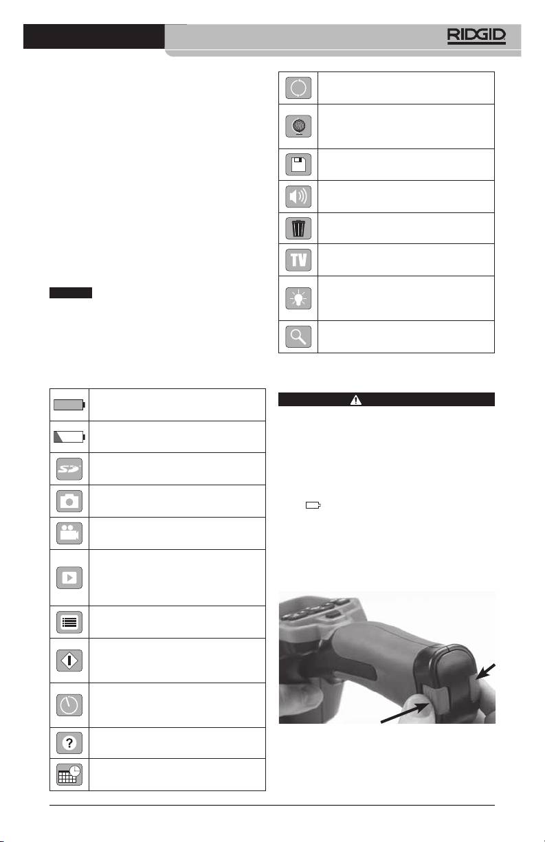
Installing SD™ Card
Adapter
Open the left side port cover (Figure 4) to ac‑
cess the SD card slot. Insert the SD card into
Installing the Imager Head Cable
the slot making sure the contacts are facing
or Extension Cables
towards you and the angled portion of the
card is facing down (Figure 10) . SD cards can
To use the micro CA‑300 Inspection Cam er a,
only be installed one way – do not force.
the imager head cable must be connected to
When an SD card is installed, a small SD card
the handheld display unit. To connect the ca‑
icon will appear in the bottom right hand
ble to the handheld display unit, make sure
portion of the screen, along with the num‑
the camera socket key and display unit sock‑
ber of images or length of video that can be
et slot (Figure 8) are properly aligned. Once
stored on the SD card.
8
micro CA-300 Inspection Camera
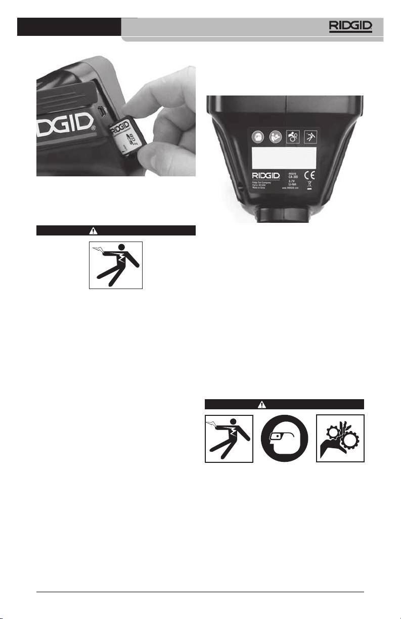
the cable to be water resistant. Con rm
unit is properly assembled.
8. Check that the warning label is present,
rmly attached and readable (Figure 11).
Figure 10 - Inserting the SD Card
Pre‑Operation Inspection
WARNING
Figure 11 - Warning Label
9. If any issues are found during the inspec‑
tion, do not use the inspection camera
until it has been properly serviced.
10. With dry hands, re‑install the battery.
11. Press and hold the Power Button for one
Before each use, inspect your Inspec tion
second. The imager lights should come
Camera and correct any problems to reduce
on, then a splash screen will appear.
the risk of serious injury from electric shock
Once the camera is ready, a live image of
and other causes and prevent tool damage.
what the camera sees is displayed on the
screen. Con sult the Troubleshooting sec‑
1. Make sure the unit is OFF.
tion of this manual if no picture appears.
2. Remove the battery and inspect it for
12. Press and hold the Power Button for one
signs of dam age. Re place battery if nec‑
second to turn camera OFF.
essary. Do not use Inspection Camera if
the battery is damaged.
Tool and Work Area Set‑Up
3. Clean any oil, grease or dirt from the e quip ‑
ment. This aids inspection and helps prevent
WARNING
the tool from slipping from your grip.
4. Inspect micro CA‑300 Inspection Camera
for any broken, worn, miss ing or binding
parts or any condition which may pre‑
vent safe and normal operation.
5. Inspect the camera head lens for con‑
densation. To avoid damaging the unit,
Set up the micro CA‑300 In spec tion Cam‑
do not use the camera if condensation
era and work area according to these pro‑
forms inside the lens. Let the water evap‑
cedures to reduce the risk of injury from
orate before using.
electrical shock, entanglement and other
causes and prevent tool damage.
6. Inspect the full length of the cable for
cracks or damage. A damaged cable
1. Check work area for:
could allow water to enter the unit and
• Adequatelighting.
increase the risk of electrical shock.
•Flammable liquids, vapors or dust that
7. Check to make sure the connections be‑
may ignite. If present, do not work in area
tween the handheld unit, extension ca‑
until sources have been identied and
bles and imager cable are tight. All con‑
corrected. The micro CA‑300 In spection
nections must be properly assembled for
9
micro CA-300 Inspection Camera
Camera is not explosion proof and can
• Determineifanymovingpartsarepres‑
cause sparks.
ent in the area to be inspected. If so,
these parts must be deactivated to pre‑
•Clear,level,stable,dryplaceforoperator.
vent movement during inspection to
Do not use the inspection camera while
reduce the risk of entanglement. Use
standing in water.
appropriate lock out procedures to pre‑
2. Examine the area or space that you will
vent the parts from moving during the
be inspecting and determine if the micro
inspection.
CA‑300 Inspection Camera is the correct
If the micro CA‑300 Inspection Camera is
piece of equipment for the job.
not the correct piece of equipment for the
• Determinetheaccesspointstothespace.
job, other inspection equipment is available
The minimum opening the cam era head
from RIDGID. For a complete listing of RIDGID
3
can t through is approximate ly
/
4
”
products, see the RIDGID catalog, online at
(19 mm) in diameter for the 17 mm cam‑
www.RIDGID.com or www.RIDGID.eu.
era head.
3. Make sure the micro CA‑300 Inspec tion
• Determinethedistancetotheareatobe
Camera has been properly inspect ed be‑
inspected. Extensions can be add ed to
fore each use.
the camera to reach up to 30’ (9 m).
4. Install the correct accessories for the ap‑
• Determineifthereareanyobstaclesthat
plication.
would require very tight turns in the
cable. The inspection camera ca ble can
Operating Instructions
go down to a 5” (13 cm) radius without
damage.
WARNING
• Determineifthereisanyelectricalpower
supplied to the area to be inspected. If
so, the power to the area must be turned
OFF to reduce the risk of electric shock.
Use appropriate lock out procedures to
prevent the power from being turned
back on during the inspection.
Always wear eye protection to protect your
• Determineifanyliquidswillbeencoun‑
eyes against dirt and other foreign objects.
tered during the inspection. The cable
and imager head are waterproof to a
Follow operating instructions to reduce the
risk of injury from electrical shock, entan‑
depth of 10’ (3 m). Greater depths may
glement and other causes.
cause leakage into the cable and imager
and cause electric shock or damage the
1. Make sure that the Inspection Camera
equipment. The handheld display unit is
and work area have been properly set up
water resistant (IP65) but should not be
and that the work area is free of bystand‑
submerged in water.
ers and other distractions.
• Determineifanychemicalsarepresent,
2. Press the Power Button for one second.
especially in the case of drains. It is im‑
The imager lights should come ON, then
portant to understand the specic safety
a splash screen will appear. This screen
measures required to work a round any
tells you the device is booting up. Once
chemicals present. Contact the chemical
the product is fully powered up, the
manufacturer for required information.
screen will automatically switch to the
Chemicals may damage or degrade the
live screen.
inspection camera.
• Determine the temperatureofthearea
and items in the area. The working tem‑
perature of the inspection camera is be‑
tween 32°F to 130°F (0°C to 55°C). Use
in areas outside of this range or contact
with hotter or colder items could cause
camera damage.
10

micro CA-300 Inspection Camera
Figure 12 - Splash Screen
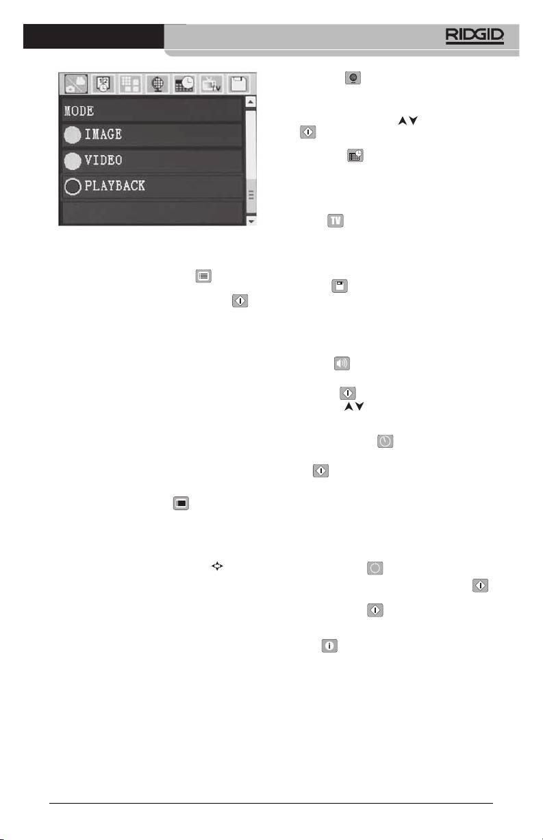
Figure 14 - Screen Shot of Mode Selection
Live Screen
The live screen is where you will do most of
3. If the other inspection camera settings
your work. A live image of what the cam‑
(such as time stamp, image quality, lan‑
era sees is displayed on the screen. You can
guage, Date/Time, TV out, and Storage
zoom, adjust LED brightness and take im‑
device) need to be adjusted, see Menu
ages or video from this screen.
Section.
The screen has a status bar at the top show‑
4. Prepare the camera for inspection. The
ing the tool mode, battery status, and an
camera cable may need to be pre‑formed
SD™ card icon if inserted, and the bottom in‑
or bent to properly inspect the area. Do
formation bar shows information about the
not try to form bends less than 5” (13 cm)
Time and Date.
radius. This can damage cable. If inspect‑
ing a dark space, turn the LEDs on before
Status Bar
inserting the camera or cable.
Do not use excessive force to insert or
withdraw the cable. This may result in
damage to the inspection camera or
inspection area. Do not use the cable
or imager head to modify surroundings,
clear pathways or clogged areas, or as
anything other than an inspection de‑
vice. This may result in damage to the
inspection camera or inspection area.
Image Adjustment
Information Bar
Adjust LED Brightness: Pressing the right
and left arrow button
on the button pad
Figure 13 - Live Screen
(In live screen) will increase or decrease the
When the Inspection Camera is turned ON,
LED brightness. A brightness indicator bar
the default mode is for capturing still im‑
will be displayed on the screen as you adjust
ages.
brightness.
Pressing the menu button at any time will ac‑
cess the menu. The menu will overlay on the
LIVE Screen. Use the right and left arrow
buttons to switch to the MODE category. Use
the up and down arrows
to navigate be‑
tween menu items and press select
as
desired.
11
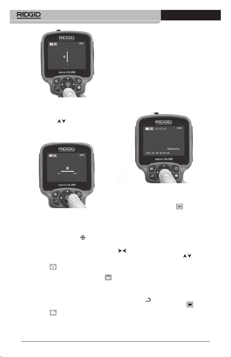
micro CA-300 Inspection Camera
cording duration will show at the top of the
screen. Press the shutter button again to stop
the video. It may take several seconds to save
the video if saving to the internal memory.
The micro CA‑300 features an integrated micro‑
phone and speaker for recording and playback
of audio with video. A headset with integrated
microphone is included and may be used instead
of the integrated speaker and microphone. Plug
the headset into the audio port on the right side
of the camera.
5. When the inspection is complete, care‑
fully withdraw the camera and cable
Figure 15 - Adjusting LED
from the inspection area.
Zoom: The micro CA‑300 Inspection Camer a
has a 3.5x digital zoom. Simply press the up
and down arrows
while in the live screen
to zoom in or out. A zoom indicator bar will
be displayed on the screen as you adjust
your zoom.
Figure 17 - Video Recording Screen
Menu
Pressing the menu button at any time
will access the menu. The menu will overlay
Figure 16 - Adjusting Zoom
on the LIVE Screen. From the menu, the user
Image Rotation: If needed, the image/video
will be able to change to the various modes
seen on the screen can be rotated in 90 de‑
or enter the settings menu.
gree increments counter clockwise by press‑
There are dierent setting categories to
ing the rotate image button
.
choose from (Figure 18) while in the settings
screen. Use the right and left arrow buttons
Image Capture
to switch from one category to the next.
Capturing a Still Image
Use the up and down arrows
to navi‑
While in the live screen, make sure the still
gate the menu items. The selected category
camera icon
is present at the top left
will be highlighted with a bright red outline.
portion of the screen. Press the shutter but‑
Once the desired setting is reached, press
ton to capture the image. The save icon
select to change to the new selection. The
will momentarily appear on the screen. This
changes are automatically saved when they
indicates the still image has been saved to
are changed.
the internal memory or SD™ card.
While in menu mode, you can press the re‑
Capturing a Video
turn button
to return to the previous
screen or hit the menu button
to exit
While in the live screen, make sure the video
the menu and return to the live screen.
camera icon
is present at the top left
portion of the screen. Press the shutter but‑
ton to start capturing video. When the device
is recording a video, a red outline will ash
around the video mode icon and the re‑
12
micro CA-300 Inspection Camera
Language
Select the “Language” icon in the menu and
press Select. Select dierent languages with
up/down arrow buttons
, then press Se‑
lect
to save the language setting.
Date/Time
Select Set Date or Set Time to set the current
date or time. Select Format Date or Time to
change how the date/time is displayed.
TV‑Out
Figure 18 - Settings Screen
Select the “NTSC” or “PAL” to enable the TV‑
Out for the video format required. Select OFF
Playback Mode
to Disable the TV‑Out.
1. Press the Menu button
, use the
Storage
down arrow to select Playback mode
icon and use the Select button
to
Select the storage icon in the menu and
enter play‑back mode. Select either Im‑
press select to format the SD™ memory card.
age or Video to playback the desired le.
This feature is normally only needed if there
The playback mode is the interface into
is an issue with the SD™ card.
saved les. It will default to the last le
recorded.
Speaker
2. While reviewing the image the user will
Select the speaker icon in the menu and
be able to cycle through all saved im‑
press select
. Select ON or OFF with up/
ages, delete an image and display le
down button
to keep the speaker ON or
informa tion.
OFF during video playback.
3. While reviewing a video, a user will be
Auto Power Off
able to navigate through videos, pause,
seek forward, restart, add bookmark and
Select the auto‑power o icon and press
delete.
select
. Select disable to turn OFF the
auto ma tic shut down function. Select the 5
Deleting Files
Minutes, 15 Minutes or 60 Minutes to turn
Press menu button
while in play‑
OFF the tool upon 5/15/60 minutes of non‑
back mode to delete the image or video.
operation. Automatic shut down setting will
The delete conrmation dialog allows
not be activated when recording or playing
the user to delete unwanted les. The ac‑
video.
tive icon is outlined in red. Navigation is
done with the arrow buttons
.
Factory Reset
Select the reset icon and press select .
Time Stamp
Conrm the reset function by selecting Yes
Enable or Disable the display of the Date and
and press Select
again. This will reset
Time.
the tool to the factory set up.
Image Quality
About
Select the desired image quality. The higher
Select the about function to display the rm‑
the image quality, the more space that will
ware revision of the micro CA‑300 as well as
be used for each le. The approximate re‑
the software copyright information.
maining number of images that can be saved
will be shown.
Transferring Images to a
Computer
Video Quality
Connect the micro CA‑300 to a computer us‑
Select the desired image quality. The higher
ing the USB cable. The USB connected screen
the video quality the more space that will be
is displayed on the micro CA‑300 screen and
used for each le. The approximate remaining
the camera is accessible as a standard USB
time that can be recorded will be shown.
storage device.
13
micro CA-300 Inspection Camera
The copy and delete options are available
from computer operation.
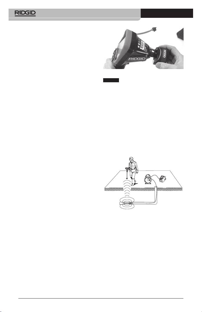
Connecting to TV
The micro CA‑300 Inspection Camera can be
connected to a television or other monitor
for remote viewing or recording through the
included RCA cable.
Open the right side port cover (Figure 3). In‑
Figure 19 - Camera Connector Plug Installed
sert the RCA cable into the TV‑Out jack. Insert
the other end of the cable into the Video‑In
NO TICE
Do not twist the connector plug to
jack on the television or monitor. Check to
prevent damage.
make sure the video format (NTSC or PAL)
Locating the Sonde
output is set properly. The television or
monitor may need to be set to the proper
If used with a sonde (In‑Line Transmitter),
input to allow viewing.
the sonde can be controlled two ways. If the
reel is equipped with a sonde key, that can
Using with SeeSnake
Inspection
be used to turn the sonde ON and OFF. Oth‑
®
erwise, the sonde is turned ON by decreas‑
Equipment
ing LED brightness to zero. Once the Sonde
The micro CA‑300 Inspection Camera can
has been located, the LEDs can be returned
also be used with various SeeSnake Inspec‑
to their normal brightness level to continue
tion Equipment and is specically designed
the inspection.
to be used with the microReel, microDrain™
A RIDGID locator such as the SR‑20, SR‑60,
and the nanoReel Inspection Systems. When
Scout, or NaviTrack® II set to 512 Hz can be
used with these types of equipment, it retains
used to locate features in the drain being in‑
all of the functionality described in this man‑
spected.
ual. The micro CA‑300 Inspection Camera can
also be used with other SeeSnake Inspection
Equipment for viewing and recording only.
For use with SeeSnake Inspection Equip‑
ment, the imager head and any cable exten‑
sions must be removed. For the microReel,
microDrain, nanoReel and similar equip‑
ment, see the operator’s manual for informa‑
tion on proper connection and use. For other
SeeSnake Inspection Equipment (typically a
reel and monitor), an adapter must be used
to connect the micro CA‑300 Inspection
Camer a to a Video‑Out port on the SeeSnake
Figure 20 - Locating the Reel Sonde
Inspec tion Equipment. When connected in
this manner, the micro CA‑300 Inspection
To locate the Sonde, turn the locator ON and
Camera will display the camera view and can
set it to Sonde mode. Scan in the direction of
be used for recording.
the Sonde’s probable location until the loca‑
When connecting to SeeSnake Inspection Equip‑
tor detects the Sonde. Once you have detect‑
ment (microReel, microDrain™, or nano ‑Reel),
ed the Sonde, use the locator indications to
align the interconnect module connected to your
zero in on its location precisely. For detailed
reel with the cable connector onthe micro CA‑300
instructions on Sonde locating, consult the
Inspection Camera, and slide it straight in, seating
Oper ator’s Manual for the locator model you
it squarely. (See Figure 19.)
are using.
14
micro CA-300 Inspection Camera
Maintenance
Storage
The RIDGID micro CA‑300 Inspection Cam era
WARNING
must be stored in a dry secure area between
Remove batteries before cleaning.
‑4°F (‑20°C) and 158°F (70°C) and humidity
between 15% and 85% RH.
• Alwayscleantheimagerheadandcable
after use with mild soap or mild deter‑
Store the tool in a locked area, out of the
gent.
reach of children and people unfamiliar with
the micro CA‑300 Inspection Cam era.
• Gently clean the display screen with a
clean dry cloth. Avoid rubbing too hard.
Remove the battery before any long period
of storage or shipping to avoid battery leak‑
• Use only alcohol swabs to clean the
age.
cable connections.
• Wipethehandhelddisplayunitdown
Service and Repair
with a clean, dry cloth.
Reset Function
WARNING
Improper service or repair can make the
If the unit stops functioning and does not
RIDGID micro CA‑300 Inspection Camera
operate, press the Reset Button (under the
unsafe to operate.
left side port cover – Figure 4). The unit may re‑
cover to normal operation when re started.
Service and repair of the micro CA‑300 In spec‑
tion Camera must be performed by a RIDGID
In dependent Authorized Service Center.
Accessories
For information on your nearest RIDGID In‑
WARNING
depen dent Service Center or any service or
repair questions:
To reduce the risk of serious injury, only use
accessories specifically designed and rec‑
• ContactyourlocalRIDGIDdistributor.
ommended for use with the RIDGID micro
• Visitwww.RIDGID.comorwww.RIDGID.eu
CA‑300 Inspection Camera such as those
listed below. Other Ac ces sories suitable
to nd your local RIDGID contact point.
for use with other tools may be hazardous
• ContactRIDGIDTechnicalServicesDe‑
when used with the micro CA‑300 Inspec‑
partment at rtctechservices@emerson.
tion Camera.
com, or in the U.S. and Canada call (800)
micro CA-300 Inspection Camera
519‑3456.
Accessories
Disposal
Catalog
Parts of the RIDGID micro CA‑300 Inspection
No. Description
Camera contain valuable materials and can
37108 3’ (90 cm) Cable Extension
be recycled. There are companies that spe‑
37113 6' (180 cm) Cable Extension
cialize in recycling that may be found locally.
Dispose of the com ponents in compliance
37103 Imager Head and 90 cm Cable ‑
17 mm
with all applicable regulations. Contact your
local waste management authority for more
37098 1m length 6 mm diameter imager
information.
37123 17 mm Accessory Pack (Hook,
Magnet, Mirror)
For EC Countries: Do not dispose of
elec trical equipment with house‑
40028 AC Adapter
hold waste!
40623 Headset Accessory with
Microphone
According to the European Guide‑
line 2002/ 96/EC for Waste Elec‑
trical and Electronic Equipment
and its imple men tation into na‑
Further information on accessories speci c to
tional legislation, electrical equipment that
this tool can be found in the RIDGID Catalog and
is no longer usable must be collected sepa‑
online at www.RIDGID.com or www.RIDGID.eu.
rately and disposed of in an environmentally
correct manner.
15

micro CA-300 Inspection Camera
Troubleshooting
SYMPTOM POSSIBLE REASON SOLUTION
Display turns ON, but
Loose cable connections. Check cable connections, clean if re‑
does not show image.
quired. Re‑attach.
Imager is broken. Replace the Imager.
Imager head covered by debris. Visually inspect imager head to make
certain it is not covered by debris.
LEDs on imager head
Battery low on power. Replace battery with charged bat‑
are dim at max bright-
tery.
ness, display switches
between black and
white, color display
turns itself OFF after a
brief period.
Unit will not turn ON. Dead battery. Replace with charged battery.
Unit need to be reset. Reset unit. See “Maintenance” Sec-
tion.
Battery Pack/Battery
care of the battery may result in battery
Charger Safety
leakage, electrical shock and burns.
WARNING
• Use an appropriate power source.
Do not attempt to use a step‑up trans‑
To reduce the risk of serious injury, read
these precautions carefully before using
former or an engine generator, doing
the battery charger or battery
so may cause damage to the charger
resulting in electrical shock, re or
Battery Charger Safety
burns.
• Do not allow anything to cover the
• Charge only the RIDGID rechargeable
charg er while in use. Proper ventilation
battery listed in the Accessories Sec-
is required for correct operation of the
tion with the RIDGID Battery Char-
charger. Allow a minimum of 4” (10 cm) of
ger. Other types of batteries may burst
clearance around the charger for proper
causing personal injury and property
ventilation.
damage.
• Unplug the charger when not in use.
• Do not probe battery charger with
This reduces the risk of injury to chil‑
conductive objects. Shorting of bat‑
dren and untrained persons.
tery terminals may cause sparks, burns
or electrical shock.
• Unplug the charger from outlet be-
fore attempting any maintenance or
• Do not insert battery into charger if
cleaning. Reduces the risk of electrical
charger has been dropped or dam-
shock.
aged in any way. A damaged charger
increases the risk of electrical shock.
• Do not charge battery in damp, wet
or explosive environment. Do not
• Charge battery in temperatures above
expose to rain, snow or dirt. Contami‑
32°F (0°C) and below 122°F (50°C).
nants and moisture increase the risk of
Store charger in temperatures above ‑4°F
electrical shock.
(‑20°C) and below 104°F (40°C). Storage
for a long time at temperatures above
• Do not open the charger housing.
104°F (40°C) can reduce the capacity of
Have repairs performed only at autho‑
the battery. Proper care will prevent se‑
rized locations.
rious damage to the battery. Improper
16
micro CA-300 Inspection Camera
• Do not carry charger by power cord.
Description and
Reduces the risk of electrical shock.
Specifications
• The RIDGID Battery Charger is not
intended for use by persons (includ‑
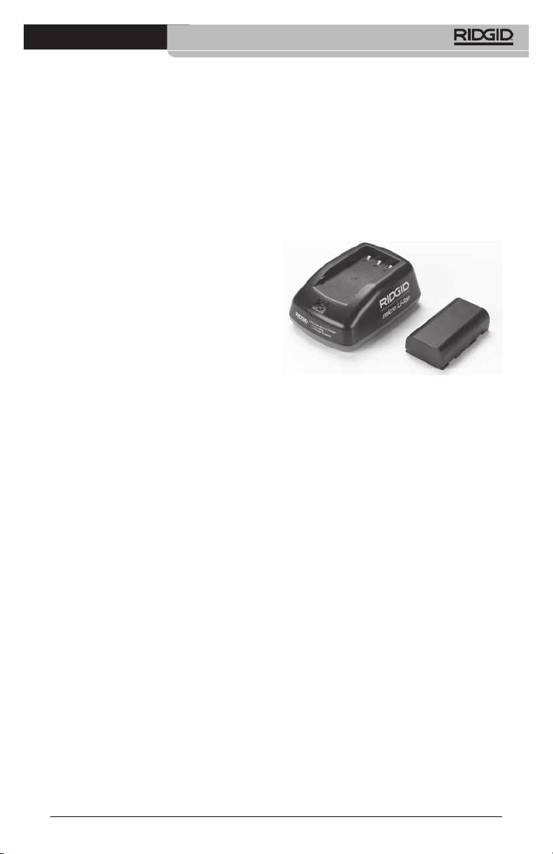
Description
ing children) with reduced physical,
The RIDGID Battery Charger (Catalog Num‑
sensory or mental capabilities, or lack
ber 37088), when used with appropriate bat‑
of experience and knowledge, un‑
teries (Catalog Number 37083) listed in the
less they have been given supervision
Accessories section, is designed to charge a
or instruction concerning use of the
3.7V Li‑Ion RIDGID battery in approximately
RIDGID Battery Charger by a person
4 ‑ 5 hours. This charger requires no adjust‑
responsible for their safety.
ments.
• Keep children and by-standers away
while operating equipment. Distrac‑
tions can cause you to lose control.
• Have your equipment (including
power supply cord) serviced by a
qualied repair person using only
identical replacement parts. If the
equipment is damaged, it must be
replaced by the manufacturer, its
service agent or similarly qualied
persons in order to avoid a hazard.
This will ensure that the safety of the
tool is maintained.
Figure 21 - Battery and Charger
Battery Safety
Specifications
• Properly dispose of the battery. Ex po‑
Input.............................. 100 ‑ 240 VAC, 50 / 60 Hz
sure to high temperatures can cause the
battery to explode, so do not dispose of
Output.......................... 4.2V DC
in a re. Place tape over the terminals
Battery Type................ 3.7V Li‑Ion
to prevent direct contact with other ob‑
Battery Capacity........ 4.2Ah
jects. Some countries have regulations
concerning battery disposal. Please fol‑
Input Current ............ 0.3A (AC) / 1A (DC)
low all applicable regulations.
Weight.......................... 0.4 lbs (0,02kg)
• Do not insert the battery with cracked
Charging Time........... 4 to 5 Hrs
case into charger. Damaged batteries
Cooling......................... Passive Convection
increase the risk of electrical shock.
Cooling (No Fan)
• Never disassemble battery. There are
no user‑serviceable parts inside the
battery. Disassembling batteries may
cause electrical shock or personal in‑
jury.
• Avoid contact with uids oozing from
defective battery. Fluids may cause
burns or skin irritation. Thoroughly rinse
with water in case of accidental contact
with uid. Consult doctor if uid comes
into contact with eyes.
17
micro CA-300 Inspection Camera
Charger Inspection and
Set‑Up
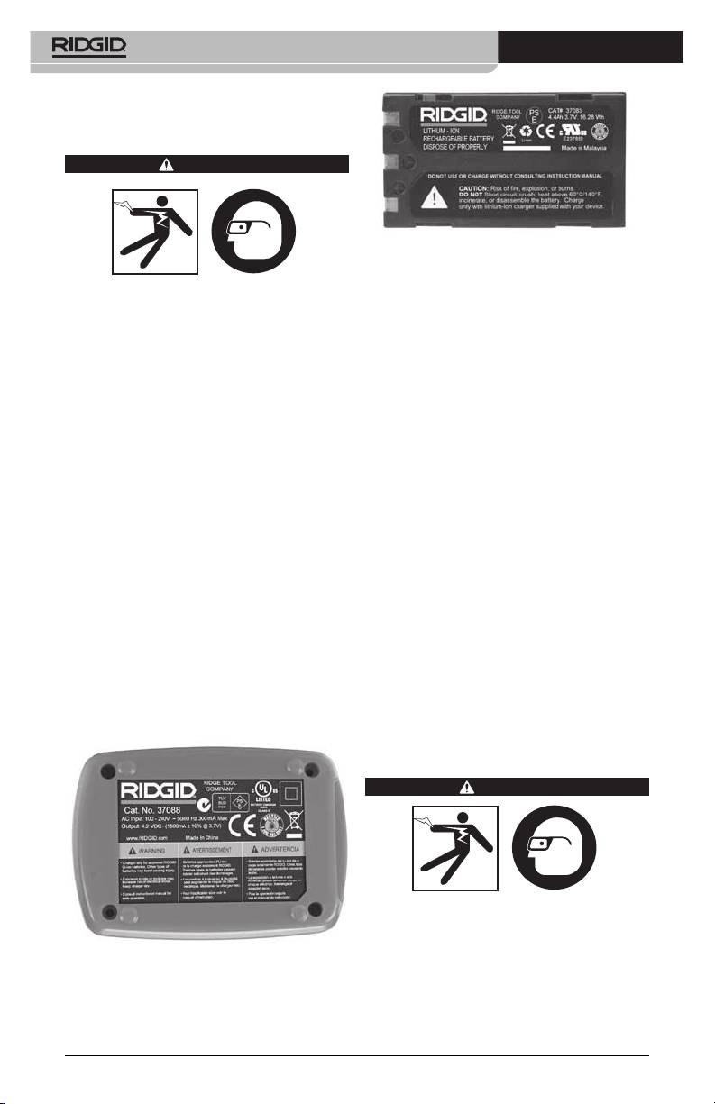
WARNING
Figure 23 - Label on Battery
4. Select an appropriate location for the char‑
Before use, inspect the charger and batter‑
ger before use. Check work area for:
ies and correct any problems. Set up char‑
• Adequatelighting.
ger according to these procedures to reduce
the risk of injury from electrical shock, fire,
• Clear,level,stable,dryplaceforcharger.
and other causes and prevent tool and sys‑
Do not use the device in wet or damp
tem damage. Always wear eye protection
areas.
to protect your eyes against dirt and other
• Proper operating temperature range.
foreign objects.
The charger and battery must both be
1. Make sure the charger is unplugged. In‑
between 32°F (0°C) and 122°F (50°C) for
spect the power cord, charger and bat‑
charging to begin. If the temperature
tery for damage or modications, or bro‑
of either is outside of this range at any
ken, worn, missing, misaligned or binding
point during charging, the operation
parts. If any problems are found, do not
will be suspended until brought back
use charger until the parts have been re‑
to the correct temperature range.
paired or replaced.
• Appropriate power source. Check to
2. Clean any oil, grease or dirt from the equip‑
see that the plug ts correctly into the
ment as described in the Cleaning Instruc‑
desired outlet.
tions section, especially handles and con‑
• Sucientventilation.Thechargerneedsa
trols. This helps prevent the equipment from
clearance of at least 4” (10 cm) on all sides
slipping from your grip and allows proper
to maintain a proper operating tempera‑
ventilation.
ture.
3. Check to see that all warning labels and
5. Plug cord into charger.
decals on the charger and battery are in‑
6. With dry hands, plug charger into the appro‑
tact and readable. (See Figures 22 & 23.)
priate power source.
Charging Procedure/
Operating Instructions
WARNING
Always wear eye protection to protect your
eyes against dirt and other foreign objects.
Follow operating instructions to reduce the
Figure 22 - Label on Charger
risk of injury from electrical shock.
NOTE! New batteries reach their full capacity
after approximately 5 charging and
discharging cycles.
18

micro CA-300 Inspection Camera
1. Set up charger according to the Charger
Further information on accessories specic to the
Inspection and Set Up section.
charger can be found in the RIDGID Catalog and
online at www.RIDGID.com or www.RIDGID.eu.
2. The charger conducts a 1‑second life test
during which the LED blinks from red to
green. The charger then goes into stand‑
Storage
by mode in which the LED is OFF.
Store the charger and the batteries in a dry,
3. With dry hands, insert the battery pack
secured, locked area that is out of reach of
onto the charger. The battery pack will
children and people not familiar with proper
begin charging automatically. While the
charger operation.
battery is charging, the red LED will glow
The batteries and charger should be pro‑
solid.
tected against hard impacts, moisture and
4. When the battery is fully charged, the
humidity, dust and dirt, extreme high and
green LED glows solid. Remove the bat‑
low temperatures and chemical solutions
tery. Once the battery is charged, it may
and vapors.
remain on the charger until it is ready to
Long‑term storage in temperatures above
be used. There is no risk of over‑charging
104°F (40°C) can permanently reduce the ca‑
the battery. When the battery has been
pacity of the batteries.
fully charged, the charger automatically
switches to retention charging.
Service and Repair
5. With dry hands, unplug the charger from
the outlet once charging is complete.
WARNING
Improper service or repair can make the
Cleaning Instructions
RIDGID micro CA‑300 Inspection Camera
unsafe to operate.
WARNING
There are no user‑serviceable parts for this
Unplug the charger before cleaning. Do not
charger or batteries. Do not attempt to open
use any water or chemicals to clean charger
charger or battery cases, charge individual
or batteries to reduce the risk of electrical
shock.
battery cells or clean internal components.
Service and repair of the charger must be
1. If present, remove battery from charger.
performed by a RIDGID Independent Author‑
2. Remove any dirt or grease from the ex‑
ized Service Center.
terior of the charger and battery with a
For information on your nearest RIDGID In‑
cloth or soft non‑metallic brush.
depen dent Service Center or any service or
repair questions:
Accessories
• ContactyourlocalRIDGIDdistributor.
• Visitwww.RIDGID.comorwww.RIDGID.eu
WARNING
to nd your local RIDGID contact point.
To reduce the risk of serious injury, only use
accessories specifically designed and rec‑
• ContactRIDGIDTechnicalServicesDe‑
ommended for use with the RIDGID Li‑Ion
partment at rtctechservices@emerson.
Battery Charger such as those listed below.
com, or in the U.S. and Canada call (800)
Other Accessories suitable for use with oth‑
519‑3456.
er tools may be hazardous when used with
the RIDGID Li‑Ion Battery Charger.
Catalog
No. Description
37088 micro CA‑300 Charger
37083 micro CA‑300 3.7V Li‑Ion Battery
30758 microEXPLORER Charger
30198 microEXPLORER 3.7V Li‑Ion
Battery
19

micro CA-300 Inspection Camera
Disposal
RIDGID® is licensed with the
Call2Recycle® program, oper‑
ated by the Rechargeable Bat‑
tery Recycling Corporation
(RBRC). As a licensee, RIDGID
pays the cost of recycling
RIDGID rechargeable batteries.
In the U.S. and Canada, RIDGID and other bat‑
tery suppliers use the Call2Recycle program
network of over 30,000 collection locations
to collect and recycle rechargeable batter‑
ies. This helps protect the environment and
conserve natural resources. Return your used
batteries to a collection location for recycling.
Call the toll‑free number found on the RBRC
recycling seal (1.800.822.8837) or visit www.
call2recycle.org for collection locations.
For EC Countries: Defective or used battery
packs/batteries must be recycled according
to the guideline 2006/66/EEC.
20
