Motorola DP 1400: instruction
Class: Home & Office Phones/Radios
Type:
Manual for Motorola DP 1400
FrontCover_HalfLetter_template.fm Page 1 Friday, May 17, 2013 2:49 PM
PROFESSIONAL DIGITAL TWO-WAY RADIOS
TM
MOTOTRBO
DP1400
NON-DISPLAY PORTABLE
USER GUIDE
EN FR IT ESDE PL RU ARTU

EMEA.book Page ii Tuesday, May 14, 2013 2:00 PM

EMEA.book Page i Tuesday, May 14, 2013 2:00 PM
Programmable Buttons . . . . . . . . . . . . . . . . . . . . . . . 7
Contents
Assignable Radio Functions . . . . . . . . . . . . . . . . . 7
Contents
This User Guide contains all the information you need to
Assignable Settings or Utility Functions . . . . . . . . . 8
use the MOTOTRBO DP1400 Portable Radio.
Push-To-Talk (PTT) Button . . . . . . . . . . . . . . . . . . . . 8
Switching Between Conventional Analog and
Important Safety Information . . . . . . . . . . . . . . . . . iii
Digital Mode . . . . . . . . . . . . . . . . . . . . . . . . . . . . . . . 9
RF Energy Exposure and Product Safety Guide
for Portable Two-Way Radios . . . . . . . . . . . . . . . .iii
Identifying Status Indicators . . . . . . . . . . . . . . . . . . 10
LED Indicator . . . . . . . . . . . . . . . . . . . . . . . . . . . . . 10
Firmware Version . . . . . . . . . . . . . . . . . . . . . . . . . . . iii
Audio Tones . . . . . . . . . . . . . . . . . . . . . . . . . . . . . . 11
Computer Software Copyrights . . . . . . . . . . . . . . . iv
Indicator Tones . . . . . . . . . . . . . . . . . . . . . . . . . . . . 11
Handling Precautions . . . . . . . . . . . . . . . . . . . . . . . . v
Receiving and Making Calls . . . . . . . . . . . . . . . . . . 12
Getting Started . . . . . . . . . . . . . . . . . . . . . . . . . . . . . . 1
Selecting a Channel . . . . . . . . . . . . . . . . . . . . . . . . 12
How to Use This Guide . . . . . . . . . . . . . . . . . . . . . . . 1
Receiving and Responding to a Radio Call . . . . . . 13
What Your Dealer/System Administrator
The LED lights up solid green while the radio is
Can Tell You . . . . . . . . . . . . . . . . . . . . . . . . . . . . . . 1
transmitting. . . . . . . . . . . . . . . . . . . . . . . . . . . . . . 13
Receiving and Responding to a Group Call . . . . . 13
Preparing Your Radio for Use . . . . . . . . . . . . . . . . . . 2
Receiving and Responding to a Private Call . . . 14
Charging the Battery . . . . . . . . . . . . . . . . . . . . . . . . . 2
Receiving an All Call . . . . . . . . . . . . . . . . . . . . . . 15
Attaching the Battery . . . . . . . . . . . . . . . . . . . . . . . . . 2
Making a Radio Call . . . . . . . . . . . . . . . . . . . . . . . . 15
Attaching the Antenna . . . . . . . . . . . . . . . . . . . . . . . . 3
Making a Group Call . . . . . . . . . . . . . . . . . . . . . 16
Attaching the Belt Clip . . . . . . . . . . . . . . . . . . . . . . . . 3
Making a Private Call . . . . . . . . . . . . . . . . . . . . 16
Powering Up the Radio . . . . . . . . . . . . . . . . . . . . . . . 4
Making a Selective Call . . . . . . . . . . . . . . . . . . . 17
Adjusting the Volume . . . . . . . . . . . . . . . . . . . . . . . . 4
Talkaround . . . . . . . . . . . . . . . . . . . . . . . . . . . . . . . 17
Identifying Radio Controls . . . . . . . . . . . . . . . . . . . . 5
Monitoring Features . . . . . . . . . . . . . . . . . . . . . . . . 18
Radio Controls . . . . . . . . . . . . . . . . . . . . . . . . . . . . . 6
i
English

EMEA.book Page ii Tuesday, May 14, 2013 2:00 PM
Monitoring a Channel . . . . . . . . . . . . . . . . . . . . . 18
Privacy . . . . . . . . . . . . . . . . . . . . . . . . . . . . . . . . . 28
Permanent Monitor . . . . . . . . . . . . . . . . . . . . . . . 19
Analog Scrambling . . . . . . . . . . . . . . . . . . . . . . . . 29
Lone Worker . . . . . . . . . . . . . . . . . . . . . . . . . . . . . . 29
Advanced Features . . . . . . . . . . . . . . . . . . . . . . . . . 20
Password Lock Features . . . . . . . . . . . . . . . . . . . . 30
Scan Lists . . . . . . . . . . . . . . . . . . . . . . . . . . . . . . . . 20
Accessing the Radio from Password . . . . . . . . . 30
Scan . . . . . . . . . . . . . . . . . . . . . . . . . . . . . . . . . . . . 21
Unlocking the Radio from Locked State . . . . . . . 31
Starting and Stopping Scan . . . . . . . . . . . . . . . . 21
Auto-Range Transponder System (ARTS) . . . . . . . 31
Responding to a Transmission During a Scan . . 21
Utilities . . . . . . . . . . . . . . . . . . . . . . . . . . . . . . . . . . 32
Deleting a Nuisance Channel . . . . . . . . . . . . . . . 22
Setting the Squelch Level . . . . . . . . . . . . . . . . . 32
Restoring a Nuisance Channel . . . . . . . . . . . . . . 22
Setting the Power Level . . . . . . . . . . . . . . . . . . . 32
Vote Scan . . . . . . . . . . . . . . . . . . . . . . . . . . . . . . . 23
Turning the Voice Operating Transmission (VOX)
Call Indicator Settings . . . . . . . . . . . . . . . . . . . . . . 23
Feature On or Off . . . . . . . . . . . . . . . . . . . . . . . . 33
Escalating Alarm Tone Volume . . . . . . . . . . . . . . 23
Voice Announcement . . . . . . . . . . . . . . . . . . . . . 33
Call Alert Operation . . . . . . . . . . . . . . . . . . . . . . . . 23
Turning Radio Tones/Alerts On or Off . . . . . . . . 34
Receiving and Responding to a Call Alert . . . . . 23
Checking the Battery Strength . . . . . . . . . . . . . . 34
Making a Call Alert with the One Touch
Access Button . . . . . . . . . . . . . . . . . . . . . . . . . . 24
Batteries Warranty . . . . . . . . . . . . . . . . . . . . . . . . . 35
Emergency Operation . . . . . . . . . . . . . . . . . . . . . . 24
Limited Warranty . . . . . . . . . . . . . . . . . . . . . . . . . . . 35
Sending an Emergency Alarm . . . . . . . . . . . . . . 25
Sending an Emergency Alarm with Call . . . . . . . 25
Sending an Emergency Alarm with Voice to
Follow . . . . . . . . . . . . . . . . . . . . . . . . . . . . . . . . . 26
Reinitiating an Emergency Mode . . . . . . . . . . . . 27
Contents
Exiting an Emergency Mode . . . . . . . . . . . . . . . . 27
Text Messaging Features . . . . . . . . . . . . . . . . . . . 28
Sending a Quick Text Message . . . . . . . . . . . . . 28
ii
English

EMEA.book Page iii Tuesday, May 14, 2013 2:00 PM
Important Safety Information
Firmware Version
Important Safety Information
All the features described in the following sections are
RF Energy Exposure and Product Safety Guide
supported by the radio's software version R01.00.00
for Portable Two-Way Radios
Check with your dealer or system administrator for more
ATTENTION!
details for all the features supported.
This radio is restricted to Occupational use only.
Before using the radio, read the
RF Energy Exposure and
Product Safety Guide for Portable Two-Way Radios
which
contains important operating instructions for safe usage
and RF energy awareness and control for Compliance
with applicable standards and Regulations.
For a list of Motorola-approved antennas, batteries, and
other accessories, visit the following website:
http://www.motorolasolutions.com
iii
English

EMEA.book Page iv Tuesday, May 14, 2013 2:00 PM
TM
The AMBE+2
voice coding Technology embodied in
Computer Software Copyrights
this product is protected by intellectual property rights
including patent rights, copyrights and trade secrets of
The Motorola products described in this manual may
Digital Voice Systems, Inc.
include copyrighted Motorola computer programs stored
in semiconductor memories or other media. Laws in the
This voice coding Technology is licensed solely for use
United States and other countries preserve for Motorola
within this Communications Equipment. The user of this
certain exclusive rights for copyrighted computer
Technology is explicitly prohibited from attempting to
programs including, but not limited to, the exclusive right
decompile, reverse engineer, or disassemble the Object
to copy or reproduce in any form the copyrighted
Code, or in any other way convert the Object Code into a
computer program. Accordingly, any copyrighted
human-readable form.
Motorola computer programs contained in the Motorola
U.S. Pat. Nos. #5,870,405, #5,826,222, #5,754,974,
products described in this manual may not be copied,
#5,701,390, #5,715,365, #5,649,050, #5,630,011,
reproduced, modified, reverse-engineered, or distributed
#5,581,656, #5,517,511, #5,491,772, #5,247,579,
in any manner without the express written permission of
#5,226,084 and #5,195,166.
Motorola. Furthermore, the purchase of Motorola
products shall not be deemed to grant either directly or by
Open Source Software Legal Notices
implication, estoppel, or otherwise, any license under the
This Motorola Product contains Open Source Software. For
copyrights, patents or patent applications of Motorola,
more information regarding licenses, acknowledgements,
except for the normal non-exclusive license to use that
required copyright notices, and other usage terms, refer to the
arises by operation of law in the sale of a product.
Documentation for this Motorola Product at:
https://emeaonline.motorolasolutions.com
Computer Software Copyrights
iv
English
EMEA.book Page v Tuesday, May 14, 2013 2:00 PM
Handling Precautions
Handling Precautions
The MOTOTRBO DP1400 Portable radio meets IP54
specifications with the antenna and dust cover attached. Your
radio limits protection against dust and water exposure.
•
Keep your radio clean and exposure to water should be
avoided to help ensure proper functionality and performance.
•
To clean the exterior surfaces of the radio, use a diluted
solution of mild dishwashing detergent and fresh water (i.e.
one teaspoon of detergent to one gallon of water).
•
These surfaces should be cleaned whenever a periodic visual
inspection reveals the presence of smudges, grease, and/or
grime.
The effects of certain chemicals and their vapors
can have harmful results on certain plastics.
Avoid using aerosol sprays, tuner cleaners and
other chemicals.
v
English

EMEA.book Page vi Tuesday, May 14, 2013 2:00 PM
Notes
Handling Precautions
vi
English
EMEA.book Page 1 Tuesday, May 14, 2013 2:00 PM
What Your Dealer/System Administrator
Getting Started
Can Tell You
Getting Started
Take a moment to review the following:
You can consult your dealer or system administrator about the
How to Use This Guide . . . . . . . . . . . . . . . . . . . . . . . . . page 1
following:
What Your Dealer/System Administrator
Can Tell You. . . . . . . . . . . . . . . . . . . . . . . . . . . . . . . . page 1
•
Is your radio programmed with any preset conventional
channels?
•
Which buttons have been programmed to access other
How to Use This Guide
features?
This User Guide covers the basic operation of the MOTOTRBO
•
What optional accessories may suit your needs?
Non-Display Portables.
•
What are the best radio usage practices for effective
However, your dealer or system administrator may have
communication?
customized your radio for your specific needs. Check with your
•
What maintenance procedures will help promote longer radio
dealer or system administrator for more information.
life?
Throughout this publication, the icons below are used to
indicate features supported in either the conventional Analog
mode or conventional Digital mode:
Indicates a conventional Analog Mode-Only feature.
Indicates a conventional Digital Mode-Only feature.
For features that are available in both Analog and Digital
modes, no icon is shown.
1
English
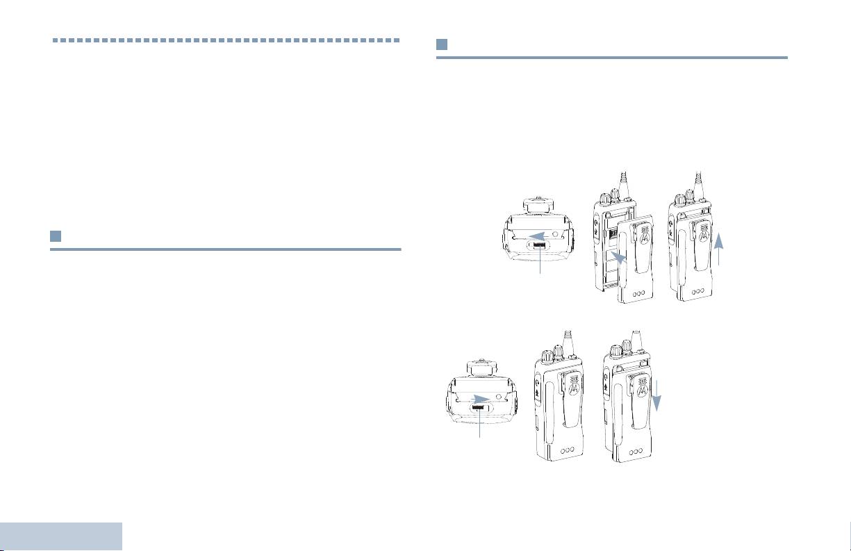
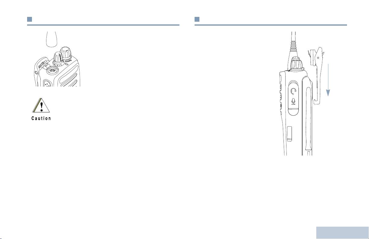
Attaching the Battery
Preparing Your Radio for Use
Ensure that the battery latch is unlocked before attaching the
Assemble your radio by following these steps:
battery. Slide the battery latch to the right and slide downwards
Charging the Battery . . . . . . . . . . . . . . . . . . . . . . . . . . . page 2
to unlock the battery. Align the battery to the battery rails on the
Attaching the Battery. . . . . . . . . . . . . . . . . . . . . . . . . . . page 2
back of the radio. Press the battery firmly to the radio and slide
Attaching the Antenna. . . . . . . . . . . . . . . . . . . . . . . . . . page 3
the battery upwards until the latch snaps into place to lock.
Attaching the Belt Clip. . . . . . . . . . . . . . . . . . . . . . . . . . page 3
Powering Up the Radio . . . . . . . . . . . . . . . . . . . . . . . . . page 4
Adjusting the Volume . . . . . . . . . . . . . . . . . . . . . . . . . . page 4
Charging the Battery
Your radio is powered by a Nickel Metal-Hydride (NiMH) or
Lithium-Ion (Li-lon) battery. To avoid damage and comply with
warranty terms, charge the battery using a Motorola charger
exactly as described in the charger user guide. Please ensure
your radio remains powered off while charging.
To remove the
battery, turn the
Charge a new battery 14 to 16 hours before initial use for best
radio off. Move the
performance.
battery latch into
unlock position and
hold. Slide the
battery down and
Preparing Your Radio for Use
lift off the rails.
2
English
Battery Latch
Battery Latch
EMEA.book Page 2 Tuesday, May 14, 2013 2:00 PM
EMEA.book Page 3 Tuesday, May 14, 2013 2:00 PM
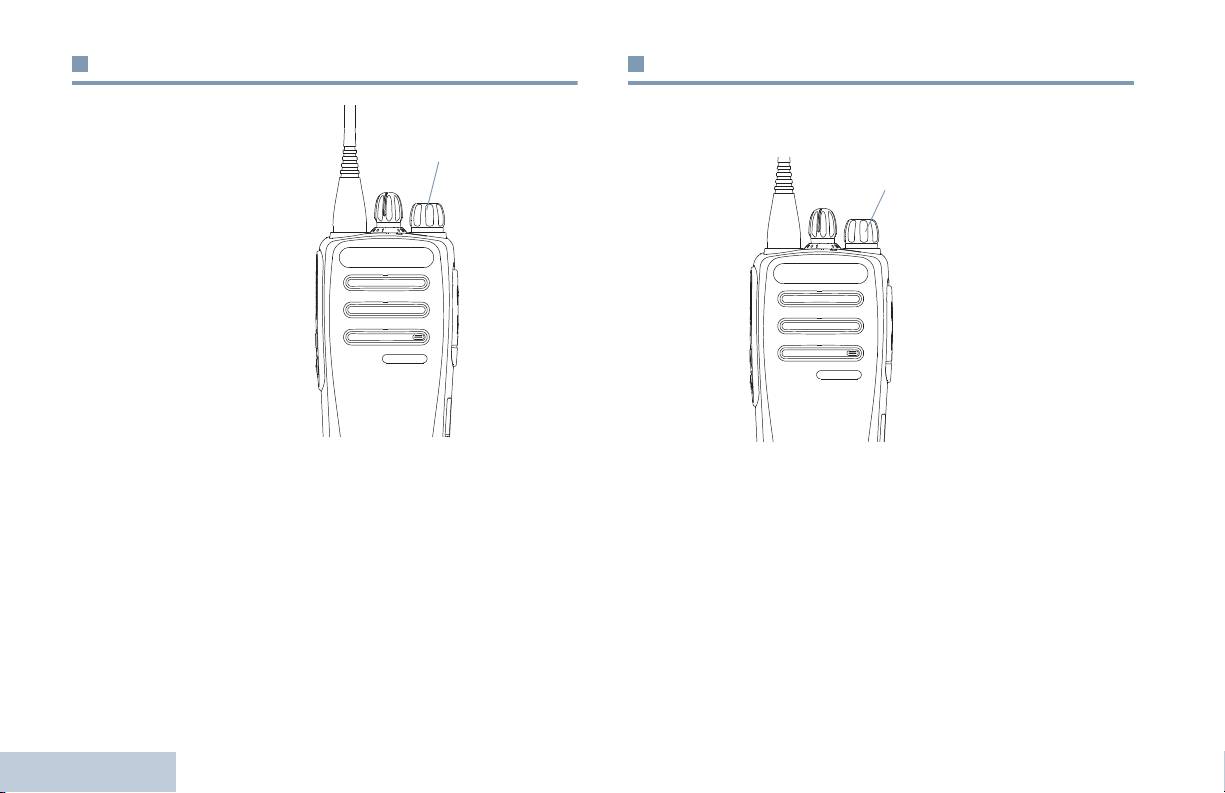
Attaching the Antenna
Attaching the Belt Clip
Preparing Your Radio for Use
With the radio turned off, set the
antenna in its receptacle and turn
Align the grooves on the clip
clockwise.
with those on the battery and
press downwards until you
To remove the antenna, turn the
hear a click.
antenna counterclockwise.
To remove the clip, press the
belt clip tab away from the
battery using a key. Then
slide the clip upwards and
If the antenna needs to be replaced, ensure that only
away from the radio.
antennas are used. Neglecting this will damage your
radio.
3
English
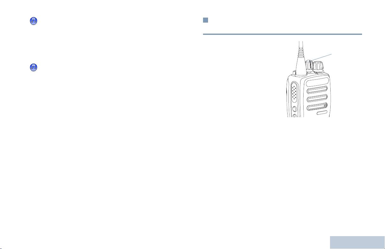
Powering Up the Radio
Adjusting the Volume
Rotate the On/Off/Volume
To increase the volume, turn the On/Off/Volume Control Knob
Control Knob clockwise
clockwise.
until you hear a click. The
LED lights up solid green.
A brief tone sounds,
indicating that the power up
test is successful.There is
no power up tone if the radio
tones/alerts function is
disabled (see Turning
Radio Tones/Alerts On or
Off on page 34).
If your radio does not power
up, check your battery.
Make sure that it is charged and properly attached. If your radio
To decrease the volume, turn this knob counterclockwise.
still does not power up, contact your dealer.
Note: Your radio can be programmed to have a minimum
To turn off the radio, rotate this knob counterclockwise until you
volume offset where the volume level cannot be turned
hear a click.
down fully. Check with your dealer or system
administrator for more information.
Preparing Your Radio for Use
4
English
On/Off/Volume Control Knob
On/Off/Volume Control Knob
EMEA.book Page 4 Tuesday, May 14, 2013 2:00 PM

EMEA.book Page 5 Tuesday, May 14, 2013 2:00 PM
Identifying Radio Controls
Identifying Radio Controls
Take a moment to review the following:
Radio Controls. . . . . . . . . . . . . . . . . . . . . . . . . . . . . . . . page 6
Programmable Buttons . . . . . . . . . . . . . . . . . . . . . . . . . page 7
Push-To-Talk (PTT) Button . . . . . . . . . . . . . . . . . . . . . . page 8
Switching Between Conventional Analog and
Digital Mode . . . . . . . . . . . . . . . . . . . . . . . . . . . . . . . . page 9
5
English
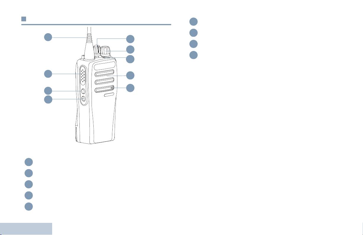
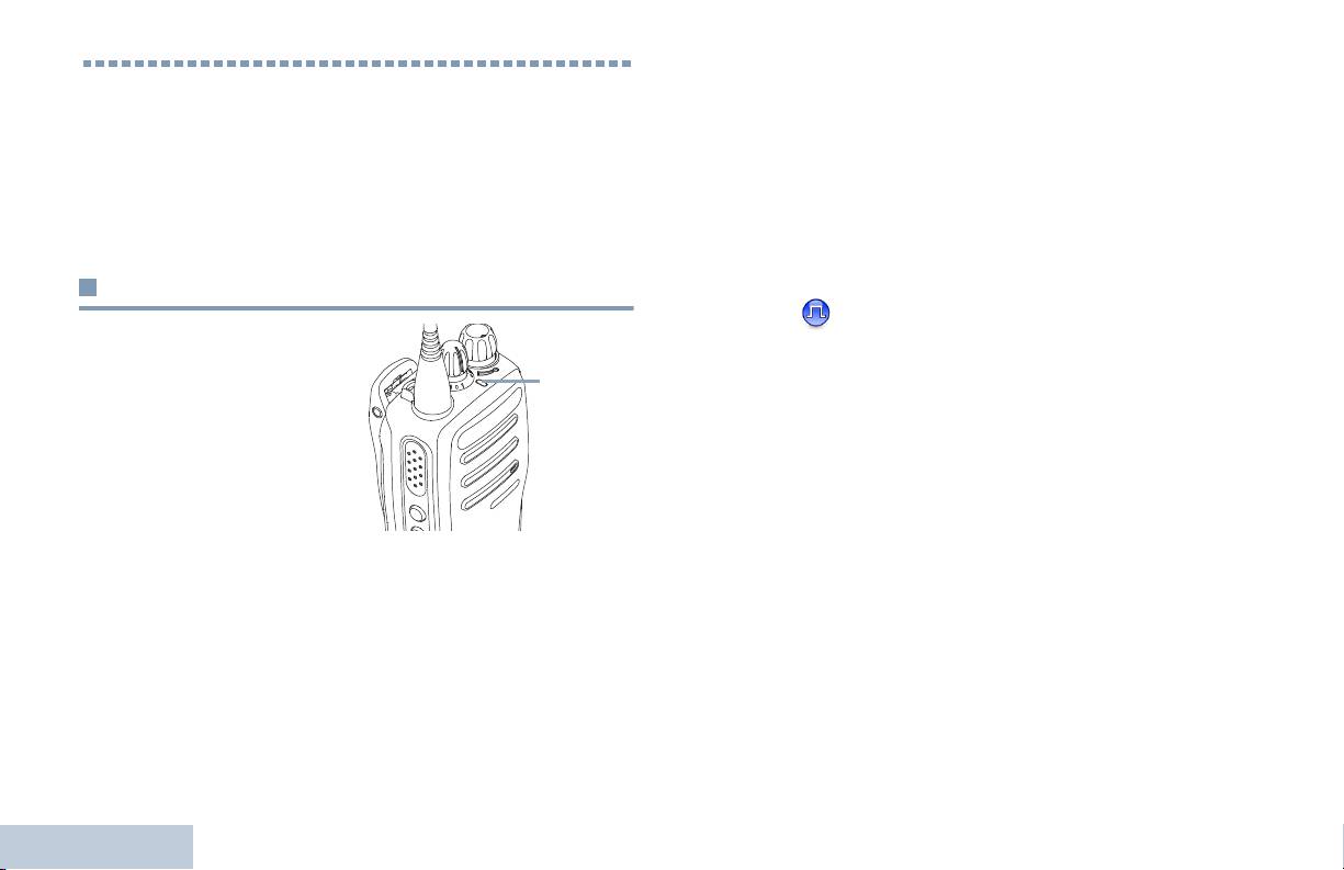
Radio Controls
Antenna
Push-to-Talk (PTT) Button
Side Button 1*
Identifying Radio Controls
Side Button 2*
Microphone
6
English
1
9
8
7
2
6
5
3
4
1
2
3
4
5
Speaker
LED Indicator
On/Off/Volume Control Knob
Channel Selector Knob
6
7
8
9
* These buttons are programmable
EMEA.book Page 6 Tuesday, May 14, 2013 2:00 PM

scan list. The Selected Channel refers to the user’s selected
Programmable Buttons
channel combination from which scan is initiated.
Identifying Radio Controls
Your dealer can program the programmable buttons as
One Touch Access – Directly initiates a predefined
shortcuts to radio functions or preset channels/groups
depending on the duration of a button press:
Private or Group Call, a Call Alert.
•
Short press – Pressing and releasing rapidly.
Permanent Monitor– Monitors a selected channel for all radio
traffic until function is disabled.
•
Long press – Pressing and holding for the programmed
duration.
Privacy – Toggles privacy on or off.
•
Hold down – Keeping the button pressed.
Repeater/Talkaround– Toggles between using a repeater and
The programmed duration of a button press is applicable for all
communicating directly with another radio.
assignable radio/utility functions or settings.
Scan – Toggles scan on or off.
Assignable Radio Functions
Voice Announcement On/Off – Toggles Voice Announcement
on or off.
Analog Scrambling – Toggles analog scrambling on or
off.
Voice Operating Transmission (VOX) – Toggles VOX on or
off.
Voice Announcement – Plays zone, channel and
programmable button announcement voice messages for the
Battery Strength – Indicates battery strength via the LED
current channel. This function is unavailable when Voice
Indicator.
Announcement is disabled.
Mic AGC On/Off – Toggles the internal microphone automatic
gain control (AGC) on or off.
Monitor – Monitors a selected channel for activity.
Nuisance Channel Delete – Temporarily removes an
unwanted channel, except for the Selected Channel, from the
7
English
EMEA.book Page 7 Tuesday, May 14, 2013 2:00 PM
Assignable Settings or Utility Functions
Push-To-Talk (PTT) Button
All Tones/Alerts – Toggles all tones and alerts on or off.
The PTT button on the
Analog Scrambling Codes – Toggles scrambling codes
side of the radio serves
between 3.29KHz and 3.39KHz.
two basic purposes:
Power Level – Toggles transmit power level between high and
•
While a call is in
low.
progress, the PTT
button allows the radio
Squelch – Toggles squelch level between tight and
to transmit to other
radios in the call.
normal.
Press and hold down
PTT button to talk.
Release the PTT
button to listen.
The microphone is
activated when the PTT button is pressed.
•
While a call is not in progress, the PTT button is used to make
a new call (see Making a Radio Call on page 15).
Depending on programming, if the Talk Permit Tone or the PTT
Sidetone is enabled, wait until the short alert tone ends
before talking.
Identifying Radio Controls
8
English
PTT
Button
EMEA.book Page 8 Tuesday, May 14, 2013 2:00 PM
During a call, if the Channel Free Indication feature is
Switching Between Conventional Analog and
enabled on your radio (programmed by your dealer), you
Digital Mode
Identifying Radio Controls
will hear a short alert tone the moment the target radio (the
radio that is receiving your call) releases the PTT button,
Each channel in your radio
indicating the channel is free for you to respond.
can be configured as a
conventional analog or
You will also hear a continuous talk prohibit tone, if your
conventional digital channel.
call is interrupted, indicating that you should release the
NOTE: For Analog-only
PTT button, for example when the radio receives an
radios, each channel
Emergency Call.
can only be
configured as a
conventional analog
channel.
Use the Channel Selector
Knob to switch between an analog or a digital channel.
When switching from digital to analog mode, certain features
are unavailable.
Your radio also has features available in both analog and digital
mode. However, the minor differences in the way each feature
works does NOT affect the performance of your radio. A
Software License Key sold separately is required to upgrade
analog-only radios to digital radios.
NOTE: Your radio also switches between digital and analog
modes during a dual mode scan (see Scan on
page 21).
9
English
Channel Selector Knob
EMEA.book Page 9 Tuesday, May 14, 2013 2:00 PM
Double blinking yellow – Indicates radio has yet to respond to
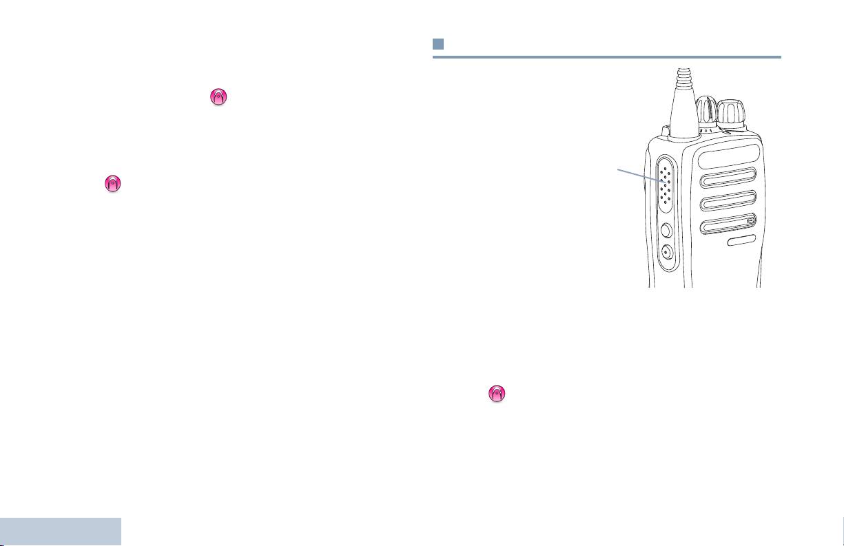
Identifying Status Indicators
a group call alert, or radio is locked.
Solid green – Radio is powering up, or transmitting. Also
Your radio indicates its operational status through the following:
indicates full charge of the battery when Battery Strength button
LED Indicator . . . . . . . . . . . . . . . . . . . . . . . . . . . . . . . page 10
is pressed.
Audio Tones . . . . . . . . . . . . . . . . . . . . . . . . . . . . . . . . page 11
Blinking green – Radio is receiving a non-privacy-enabled call
Indicator Tones . . . . . . . . . . . . . . . . . . . . . . . . . . . . . . page 11
or data, detecting activity over the air.
Double blinking green – Radio is receiving a privacy-enabled
LED Indicator
call or data.
The LED indicator shows the
NOTE: While in conventional mode, when the LED blinks
operational status of your radio.
green, it indicates the radio detects activity over the air.
Due to the nature of the digital protocol, this activity
Blinking red – Radio is
may or may not affect the radio's programmed
transmitting at low battery
channel.
condition, receiving an
emergency transmission or has
failed the self-test upon
powering up, or has moved out
of range if radio is configured with Auto-Range Transponder
System.
Solid yellow – Radio is monitoring a conventional channel.
Also indicates fair battery charge when Battery Strength button
is pressed.
Identifying Status Indicators
Blinking yellow – Radio is scanning for activity or receiving a
Call Alert.
10
English
LED
Indicator
EMEA.book Page 10 Tuesday, May 14, 2013 2:00 PM
EMEA.book Page 11 Tuesday, May 14, 2013 2:00 PM
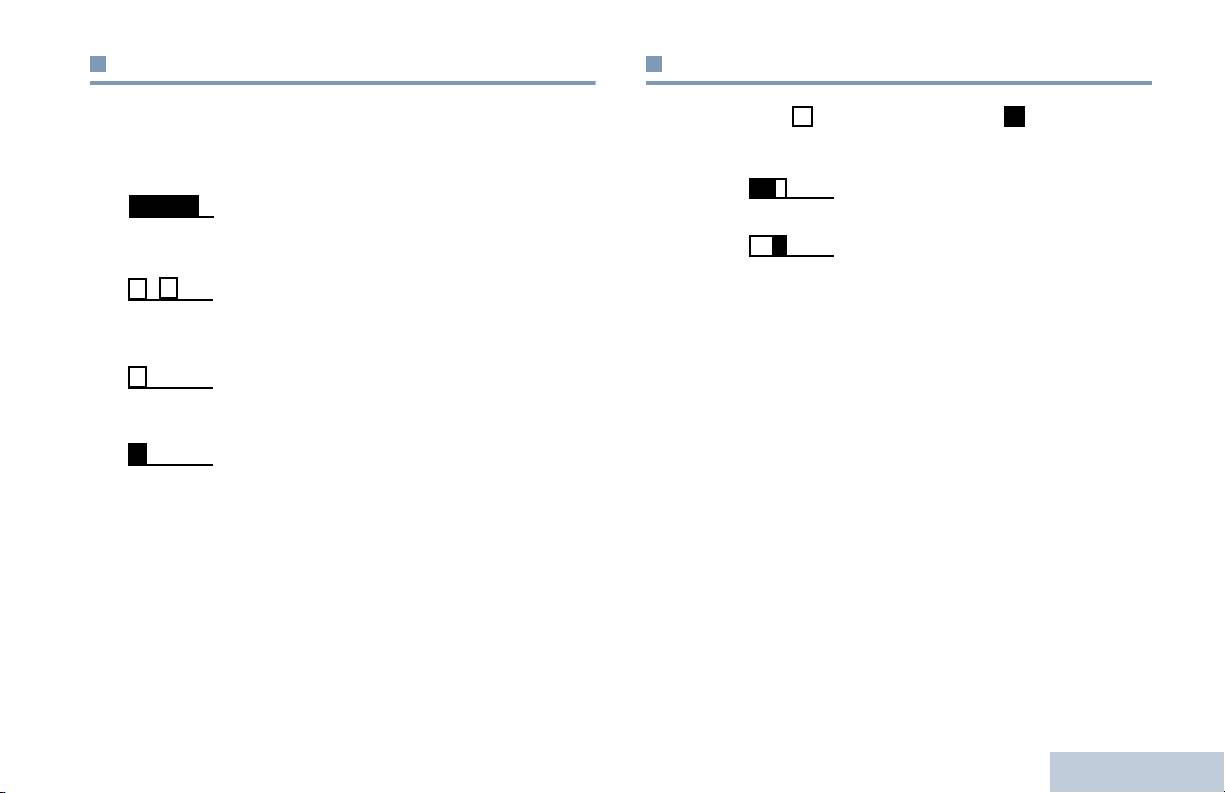
Audio Tones
Indicator Tones
Identifying Status Indicators
Alert tones provide you with audible indications of the radio’s
High pitched tone Low pitched tone
status or the radio’s response to data received.
Continuous Tone A monotone sound. Sounds
Positive Indicator Tone
continuously until termination.
Negative Indicator Tone
Periodic Tone Sounds periodically depending on the
duration set by the radio. Tone starts,
stops, and repeats itself.
Repetitive Tone A single tone that repeats itself until it is
terminated by the user.
Momentary Tone Sounds only once for a short period of
time defined by the radio.
11
English
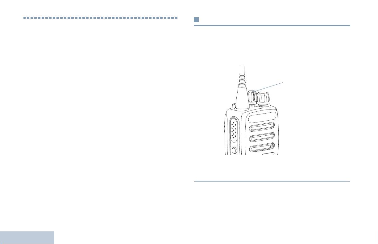
Selecting a Channel
Receiving and Making Calls
Transmissions are sent and received on a channel. Depending
Once you understand how your MOTOTRBO Portable is
on your radio’s configuration, each channel may have been
configured, you are ready to use your radio.
programmed differently to support different groups of users or
Use this navigation guide to familiarize yourself with the basic
supplied with different features. Select the relevant channel you
Call features:
require to transmit or receive on.
Selecting a Channel . . . . . . . . . . . . . . . . . . . . . . . . . . page 12
Receiving and Responding to a Radio Call. . . . . . . . . page 13
Making a Radio Call . . . . . . . . . . . . . . . . . . . . . . . . . . page 15
Talkaround . . . . . . . . . . . . . . . . . . . . . . . . . . . . . . . . . page 17
Monitoring Features . . . . . . . . . . . . . . . . . . . . . . . . . . page 18
Procedure:
Turn the Channel Selector Knob to select the number that
represents the channel, radio ID, or group ID.
Receiving and Making Calls
12
English
Channel Selector
Knob
EMEA.book Page 12 Tuesday, May 14, 2013 2:00 PM
