Motorola XPR 7350: instruction
Class: Home & Office Phones/Radios
Type:
Manual for Motorola XPR 7350
PROFESSIONAL DIGITAL TWO-WAY RADIO
MOTOTRBO™
DP4400/DP4401
NON-DISPLAY PORTABLE
USER GUIDE
EN FR IT ESDE PL RU ARTU

NKP_EMEA.book Page ii Monday, July 2, 2012 3:50 PM

NKP_EMEA.book Page i Monday, July 2, 2012 3:50 PM
Identifying Radio Controls . . . . . . . . . . . . . . . . . . . . 6
Contents
Radio Controls . . . . . . . . . . . . . . . . . . . . . . . . . . . . . 6
Contents
This User Guide contains all the information you need to
Programmable Buttons . . . . . . . . . . . . . . . . . . . . . . . 7
use the MOTOTRBO Series Portables.
Assignable Radio Functions . . . . . . . . . . . . . . . . . 7
Assignable Settings or Utility Functions . . . . . . . . . 8
Important Safety Information . . . . . . . . . . . . . . . . . iv
Push-To-Talk (PTT) Button . . . . . . . . . . . . . . . . . . . . 8
Product Safety and RF Exposure Compliance . . .iv
Switching Between Conventional Analog and
Software Version . . . . . . . . . . . . . . . . . . . . . . . . . . . iv
Digital Mode . . . . . . . . . . . . . . . . . . . . . . . . . . . . . . . 9
Computer Software Copyrights . . . . . . . . . . . . . . . . v
IP Site Connect . . . . . . . . . . . . . . . . . . . . . . . . . . . . 10
Capacity Plus . . . . . . . . . . . . . . . . . . . . . . . . . . . . . 10
Handling Precautions . . . . . . . . . . . . . . . . . . . . . . . vi
Linked Capacity Plus . . . . . . . . . . . . . . . . . . . . . . . 11
Getting Started . . . . . . . . . . . . . . . . . . . . . . . . . . . . . . 1
Identifying Status Indicators . . . . . . . . . . . . . . . . . . 12
How to Use This Guide . . . . . . . . . . . . . . . . . . . . . . . 1
LED Indicator . . . . . . . . . . . . . . . . . . . . . . . . . . . . . 12
What Your Dealer/System Administrator
Indicator Tones . . . . . . . . . . . . . . . . . . . . . . . . . . . . 13
Can Tell You . . . . . . . . . . . . . . . . . . . . . . . . . . . . . . 1
Audio Tones . . . . . . . . . . . . . . . . . . . . . . . . . . . . . . 13
Preparing Your Radio for Use . . . . . . . . . . . . . . . . . . 2
Receiving and Making Calls . . . . . . . . . . . . . . . . . . 14
Charging the Battery . . . . . . . . . . . . . . . . . . . . . . . . . 2
Selecting a Zone . . . . . . . . . . . . . . . . . . . . . . . . . . . 14
Attaching the Battery . . . . . . . . . . . . . . . . . . . . . . . . . 3
Selecting a Channel . . . . . . . . . . . . . . . . . . . . . . . . 14
Attaching the Antenna . . . . . . . . . . . . . . . . . . . . . . . . 3
Receiving and Responding to a Radio Call . . . . . . 15
Attaching the Belt Clip . . . . . . . . . . . . . . . . . . . . . . . . 4
Receiving and Responding to a Group Call . . . . . 15
Attaching the Universal Connector Cover
(Dust Cover) . . . . . . . . . . . . . . . . . . . . . . . . . . . . . . 4
Receiving and Responding to a Private Call . . . 16
Powering Up the Radio . . . . . . . . . . . . . . . . . . . . . . . 5
Receiving and Responding to a Selective Call . . 17
Adjusting the Volume . . . . . . . . . . . . . . . . . . . . . . . . 5
Receiving an All Call . . . . . . . . . . . . . . . . . . . . . . 17
i
English

NKP_EMEA.book Page ii Monday, July 2, 2012 3:50 PM
Making a Radio Call . . . . . . . . . . . . . . . . . . . . . . . . 18
Emergency Operation . . . . . . . . . . . . . . . . . . . . . . 27
Making a Call with the Channel Selector Knob . . 18
Sending an Emergency Alarm . . . . . . . . . . . . . . 27
Making a Group Call . . . . . . . . . . . . . . . . . . . . 18
Sending an Emergency Alarm with Call . . . . . . . 28
Making a Private Call . . . . . . . . . . . . . . . . . . . 19
Sending an Emergency Alarm with Voice to
Making a Selective Call . . . . . . . . . . . . . . . . . 19
Follow . . . . . . . . . . . . . . . . . . . . . . . . . . . . . . . . . 28
Making an All Call . . . . . . . . . . . . . . . . . . . . . . 20
Reinitiating an Emergency Mode . . . . . . . . . . . . 30
Stopping a Radio Call . . . . . . . . . . . . . . . . . . . . . . 21
Exiting an Emergency Mode . . . . . . . . . . . . . . . . 30
Talkaround . . . . . . . . . . . . . . . . . . . . . . . . . . . . . . . 21
Text Messaging Features . . . . . . . . . . . . . . . . . . . 30
Monitoring Features . . . . . . . . . . . . . . . . . . . . . . . . 22
Sending a Quick Text Message . . . . . . . . . . . . . 30
Monitoring a Channel . . . . . . . . . . . . . . . . . . . . . 22
Privacy . . . . . . . . . . . . . . . . . . . . . . . . . . . . . . . . . 31
Permanent Monitor . . . . . . . . . . . . . . . . . . . . . . . 22
Multi-Site Controls . . . . . . . . . . . . . . . . . . . . . . . . . 32
Advanced Features . . . . . . . . . . . . . . . . . . . . . . . . . 23
Starting an Automatic Site Search . . . . . . . . . . . 32
Scan Lists . . . . . . . . . . . . . . . . . . . . . . . . . . . . . . . . 23
Stopping an Automatic Site Search . . . . . . . . . . 32
Scan . . . . . . . . . . . . . . . . . . . . . . . . . . . . . . . . . . . . 24
Starting a Manual Site Search . . . . . . . . . . . . . . 32
Starting and Stopping Scan . . . . . . . . . . . . . . . . 24
Lone Worker . . . . . . . . . . . . . . . . . . . . . . . . . . . . . . 33
Responding to a Transmission During a Scan . . 24
Password Lock Features . . . . . . . . . . . . . . . . . . . . 33
Deleting a Nuisance Channel . . . . . . . . . . . . . . . 25
Accessing the Radio from Password . . . . . . . . . 33
Restoring a Nuisance Channel . . . . . . . . . . . . . . 25
Unlocking the Radio from Locked State . . . . . . . 34
Vote Scan . . . . . . . . . . . . . . . . . . . . . . . . . . . . . . . . 25
Bluetooth . . . . . . . . . . . . . . . . . . . . . . . . . . . . . . . . 34
Call Indicator Settings . . . . . . . . . . . . . . . . . . . . . . 26
Finding and Connecting to a Bluetooth Device . . 35
Escalating Alarm Tone Volume . . . . . . . . . . . . . . 26
Disconnecting from a Bluetooth Device . . . . . . . 35
Call Alert Operation . . . . . . . . . . . . . . . . . . . . . . . . 26
Switching Audio Route . . . . . . . . . . . . . . . . . . . . 35
Receiving and Responding to a Call Alert . . . . . 26
Utilities . . . . . . . . . . . . . . . . . . . . . . . . . . . . . . . . . . 36
Contents
Making a Call Alert with the
Setting the Squelch Level . . . . . . . . . . . . . . . . . 36
One Touch Access Button . . . . . . . . . . . . . . . . . 26
Setting the Power Level . . . . . . . . . . . . . . . . . . . 36
ii
English

NKP_EMEA.book Page iii Monday, July 2, 2012 3:50 PM
Turning the Option Board Feature(s) On or Off . . 36
Turning the Voice Operating Transmission (VOX)
Contents
Feature On or Off . . . . . . . . . . . . . . . . . . . . . . . . . 36
Turning Radio Tones/Alerts On or Off . . . . . . . . . 37
Checking the Battery Strength . . . . . . . . . . . . . . . 37
Voice Announcement . . . . . . . . . . . . . . . . . . . . . . 37
Intelligent Audio . . . . . . . . . . . . . . . . . . . . . . . . . . 38
GPS . . . . . . . . . . . . . . . . . . . . . . . . . . . . . . . . . . . 38
Batteries and Chargers Warranty . . . . . . . . . . . . . . 39
Limited Warranty . . . . . . . . . . . . . . . . . . . . . . . . . . . 40
iii
English
NKP_EMEA.book Page iv Monday, July 2, 2012 3:50 PM
Important Safety Information
Software Version
All the features described in the following sections are
Product Safety and RF Exposure Compliance
supported by the radio's software version R02.04.00.
Before using this product, read the operating
Please check with your dealer or system administrator
instructions for safe usage contained in the
for more details of all the features supported.
Product Safety and RF Exposure booklet
enclosed with your radio.
ATTENTION!
This radio is restricted to occupational use only to
satisfy FCC/ICNIRP RF energy exposure
requirements. Before using this product, read the RF
energy awareness information and operating instructions
in the Product Safety and RF Exposure booklet enclosed
with your radio (Motorola Publication part number
6864117B25) to ensure compliance with RF energy
exposure limits.
For a list of Motorola-approved antennas, batteries, and
other accessories, visit the following website:
http://www.motorolasolutions.com
Important Safety Information
iv
English

NKP_EMEA.book Page v Monday, July 2, 2012 3:50 PM
TM
The AMBE+2
voice coding Technology embodied in
Computer Software Copyrights
this product is protected by intellectual property rights
Computer Software Copyrights
including patent rights, copyrights and trade secrets of
The Motorola products described in this manual may
Digital Voice Systems, Inc.
include copyrighted Motorola computer programs stored
in semiconductor memories or other media. Laws in the
This voice coding Technology is licensed solely for use
United States and other countries preserve for Motorola
within this Communications Equipment. The user of this
certain exclusive rights for copyrighted computer
Technology is explicitly prohibited from attempting to
programs including, but not limited to, the exclusive right
decompile, reverse engineer, or disassemble the Object
to copy or reproduce in any form the copyrighted
Code, or in any other way convert the Object Code into a
computer program. Accordingly, any copyrighted
human-readable form.
Motorola computer programs contained in the Motorola
U.S. Pat. Nos. #5,870,405, #5,826,222, #5,754,974,
products described in this manual may not be copied,
#5,701,390, #5,715,365, #5,649,050, #5,630,011,
reproduced, modified, reverse-engineered, or distributed
#5,581,656, #5,517,511, #5,491,772, #5,247,579,
in any manner without the express written permission of
#5,226,084 and #5,195,166.
Motorola. Furthermore, the purchase of Motorola
products shall not be deemed to grant either directly or by
implication, estoppel, or otherwise, any license under the
copyrights, patents or patent applications of Motorola,
except for the normal non-exclusive license to use that
arises by operation of law in the sale of a product.
v
English

NKP_EMEA.book Page vi Monday, July 2, 2012 3:50 PM
• Never poke the vent (hole) located on the radio chassis
Handling Precautions
below the battery contact. This vent allows for pressure
equalization in the radio. Doing so may create a leak
The MOTOTRBO Series Digital Portable radio meets
path into the radio and the radio’s submersibility may
IP57 specifications, allowing the radio to withstand
be lost.
adverse field conditions such as being submersed in
• Never obstruct or cover the vent, even with a label.
water.
• Ensure that no oily substances come in contact with the
• If the radio has been submersed in water, shake the
vent.
radio well to remove any water that may be trapped
inside the speaker grille and microphone port. Trapped
• The radio with antenna attached properly is designed to
water could cause decreased audio performance.
be submersible to a maximum depth of 1 meter (3.28
feet) and a maximum submersion time of 30 minutes.
• If the radio’s battery contact area has been exposed to
Exceeding either maximum limit or use without antenna
water, clean and dry battery contacts on both the radio
may result in damage to the radio.
and the battery before attaching the battery to the
radio. The residual water could short-circuit the radio.
• When cleaning the radio, do not use a high pressure jet
spray on the radio as this will exceed the 1 meter depth
• If the radio has been submersed in a corrosive
pressure and may cause water to leak into the radio.
substance (e.g. saltwater), rinse the radio and battery
in fresh water then dry the radio and battery.
Do not disassemble the radio. This could
damage radio seals and result in leak paths into
• To clean the exterior surfaces of the radio, use a diluted
the radio. Radio maintenance should only be
solution of mild dishwashing detergent and fresh water
(i.e. one teaspoon of detergent to one gallon of water).
done in service depot that is equipped to test
and replace the seal on the radio.
Handling Precautions
vi
English

NKP_EMEA.book Page 1 Monday, July 2, 2012 3:50 PM
For features that are available in a conventional multi-site
Getting Started
mode, see IP Site Connect on page 10 for more information.
Getting Started
Selected features are also available on the single-site trunking
Take a moment to review the following:
mode, Capacity Plus. See Capacity Plus on page 10 for more
How to Use This Guide . . . . . . . . . . . . . . . . . . . . . . . . . page 1
information.
What Your Dealer/System Administrator
Selected features are also available in the multi-site trunking
Can Tell You. . . . . . . . . . . . . . . . . . . . . . . . . . . . . . . . page 1
mode, Linked Capacity Plus. See Linked Capacity Plus on
page 11 for more information.
How to Use This Guide
What Your Dealer/System Administrator
This User Guide covers the basic operation of the MOTOTRBO
Can Tell You
Non-Display Portables.
However, your dealer or system administrator may have
You can consult your dealer or system administrator about the
customized your radio for your specific needs. Check with your
following:
dealer or system administrator for more information.
• Is your radio programmed with any preset conventional
channels?
Throughout this publication, the icons below are used to
indicate features supported in either the conventional Analog
• Which buttons have been programmed to access other
features?
mode or conventional Digital mode:
• What optional accessories may suit your needs?
Indicates a conventional Analog Mode-Only feature.
• What are the best radio usage practices for effective
communication?
Indicates a conventional Digital Mode-Only feature.
• What maintenance procedures will help promote longer radio
life?
For features that are available in both Analog and Digital
modes, no icon is shown.
1
English

NKP_EMEA.book Page 2 Monday, July 2, 2012 3:50 PM
Charging the Battery
Preparing Your Radio for Use
For best performance, your radio is powered by a
Assemble your radio by following these steps:
Motorola-approved Nickel Metal-Hydride (NiMH) or Lithium-Ion
Charging the Battery . . . . . . . . . . . . . . . . . . . . . . . . . . . page 2
(Li-lon) battery. To avoid damage and comply with warranty
Attaching the Battery. . . . . . . . . . . . . . . . . . . . . . . . . . . page 3
terms, charge the battery using a Motorola charger exactly as
Attaching the Antenna. . . . . . . . . . . . . . . . . . . . . . . . . . page 3
described in the charger user guide.
Attaching the Belt Clip. . . . . . . . . . . . . . . . . . . . . . . . . . page 4
Charge a new battery 14 to 16 hours before initial use for best
Attaching the Universal Connector
performance.
Cover (Dust Cover) . . . . . . . . . . . . . . . . . . . . . . . . . . page 4
Powering Up the Radio . . . . . . . . . . . . . . . . . . . . . . . . . page 5
IMPORTANT: ALWAYS charge your IMPRES battery with an
Adjusting the Volume . . . . . . . . . . . . . . . . . . . . . . . . . . page 5
IMPRES charger for optimized battery life and
valuable battery data. IMPRES batteries
charged exclusively with IMPRES chargers
receive a 6-month capacity warranty extension
over the standard Motorola Premium battery
warranty duration.
Preparing Your Radio for Use
2
English
NKP_EMEA.book Page 3 Monday, July 2, 2012 3:50 PM
Attaching the Battery
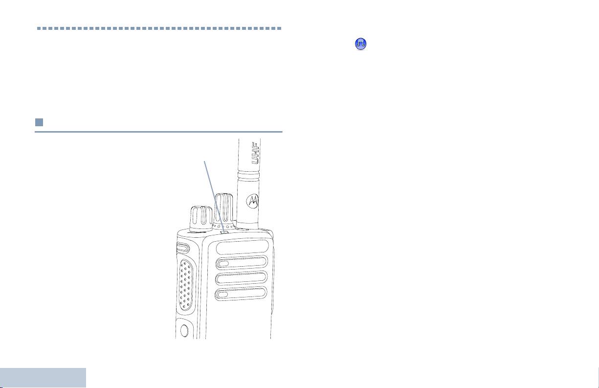
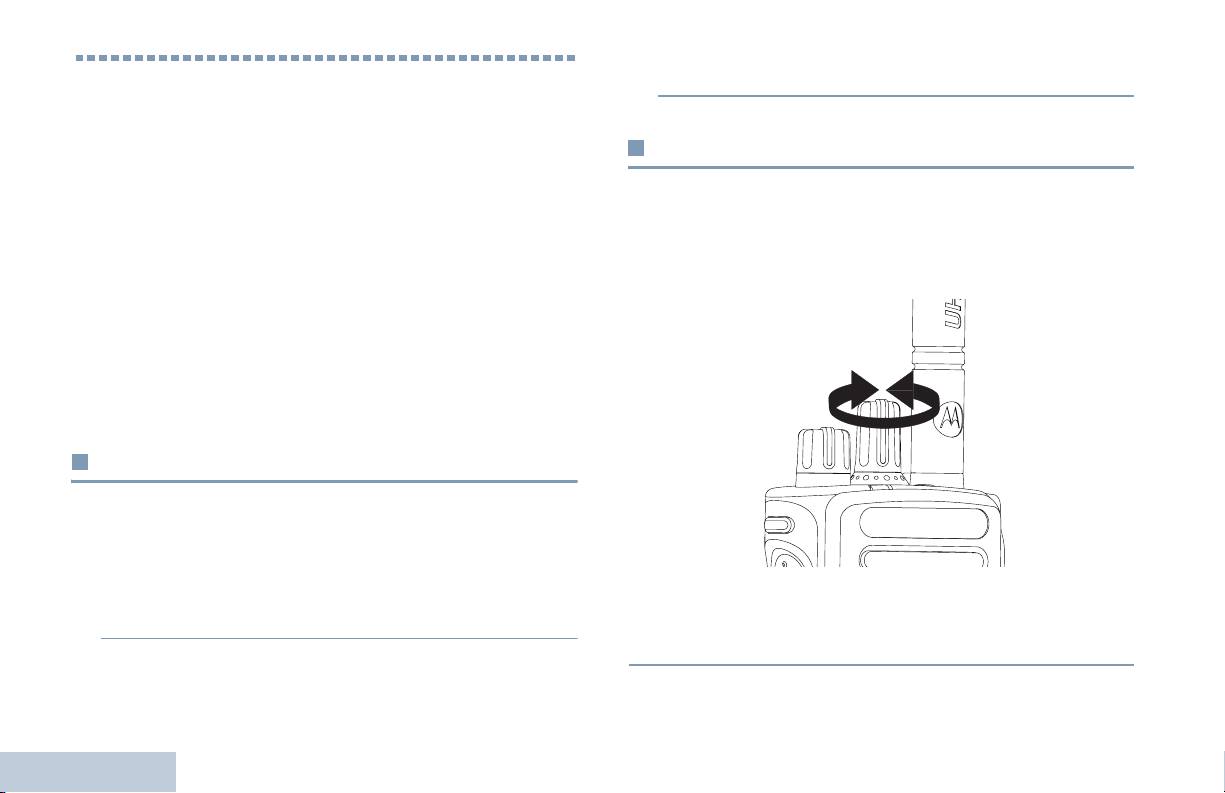
Attaching the Antenna
Preparing Your Radio for Use
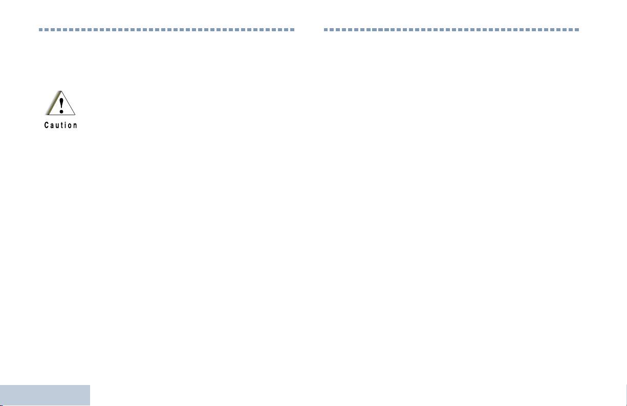
Align the battery with the rails on the back of the radio. Press
With the radio turned off, set the
the battery firmly, and slide upward until the latch snaps into
antenna in its receptacle and turn
place. Slide battery latch into lock position.
clockwise.
To remove the antenna, turn the
antenna counterclockwise.
If antenna needs to be replaced, ensure that only
MOTOTRBO antennas are used. Neglecting this will
damage your radio.
To remove the
battery, turn the
radio off. Move the
battery latch into
unlock position
and hold, and slide
the battery down
and off the rails.
Battery
Latch
3
English
NKP_EMEA.book Page 4 Monday, July 2, 2012 3:50 PM
Attaching the Belt Clip
Attaching the Universal Connector Cover
(Dust Cover)
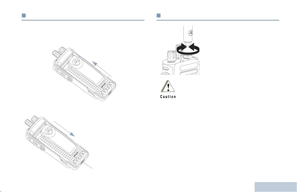
Align the grooves on the clip
The universal connector is located on the antenna side of the
with those on the battery and
radio. It is used to connect MOTOTRBO accessories to the
press downward until you
radio.
hear a click.
Insert the hooked end of the
cover into the slots above the
To remove the clip, press the
universal connector. Press
belt clip tab away from the
downward on the cover to
battery using a key. Then
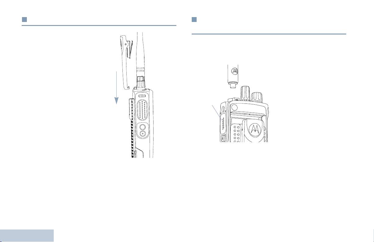
Universal
seat the lower tab properly
slide the clip upward and
Connector
into the RF connector.
away from the radio.
Turn the thumbscrew
clockwise to secure the
connector cover to the radio.
To remove the universal
connector cover, press down
on the cover and turn the thumbscrew counterclockwise.
Replace the dust cover when the universal connector is not in
use.
Preparing Your Radio for Use
4
English

NKP_EMEA.book Page 5 Monday, July 2, 2012 3:50 PM
Powering Up the Radio
Adjusting the Volume
Preparing Your Radio for Use
Rotate the On/Off/Volume
To increase the volume, turn the On/Off/Volume Control Knob
Control Knob clockwise until
clockwise.
you hear a click. The LED
lights up solid green.
A brief tone sounds,
indicating that the power up
test is successful.
NOTE: There is no power up
tone if the radio
tones/alerts function
is disabled (see
Turning Radio
Tones/Alerts On or
Off on page 37).
If your radio does not power up, check your battery. Make sure
To decrease the volume, turn this knob counterclockwise.
that it is charged and properly attached. If your radio still does
not power up, contact your dealer.
NOTE: Your radio can be programmed to have a minimum
volume offset where the volume level cannot be turned
To turn off the radio, rotate this knob counterclockwise until you
past the programmed minimum volume. Check with
hear a click.
your dealer or system administrator for more
information.
5
English
NKP_EMEA.book Page 6 Monday, July 2, 2012 3:50 PM
Identifying Radio Controls
Take a moment to review the following:
1
12
Radio Controls . . . . . . . . . . . . . . . . . . . . . . . . . . . . . . . page 6
11
Programmable Buttons . . . . . . . . . . . . . . . . . . . . . . . . . page 7
2
Push-To-Talk (PTT) Button . . . . . . . . . . . . . . . . . . . . . . page 8
10
3
Switching Between Conventional Analog and
Digital Mode. . . . . . . . . . . . . . . . . . . . . . . . . . . . . . . . page 9
4
9
IP Site Connect . . . . . . . . . . . . . . . . . . . . . . . . . . . . . . page 10
Capacity Plus . . . . . . . . . . . . . . . . . . . . . . . . . . . . . . . page 10
5
Linked Capacity Plus. . . . . . . . . . . . . . . . . . . . . . . . . . page 11
8
6
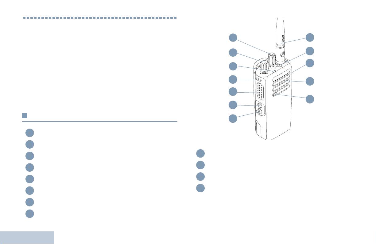
Radio Controls
7
1
Channel Selector Knob
2
On/Off/Volume Control Knob
Speaker
3
LED Indicator
9
10
Universal Connector for Accessories
4
Side Button 1*
11
Emergency Button*
5
Push-to-Talk (PTT) Button
12
Antenna
6
Side Button 2*
Identifying Radio Controls
7
Side Button 3*
* These buttons are programmable.
8
Microphone
6
English

NKP_EMEA.book Page 7 Monday, July 2, 2012 3:50 PM
Call Forwarding – Toggles Call Forwarding on or off.
Programmable Buttons
Voice Announcement for Channel – Plays zone and channel
Identifying Radio Controls
Your dealer can program the programmable buttons as
announcement voice messages for the current channel. This
shortcuts to radio functions or preset channels/groups
function is unavailable when Voice Announcement is disabled.
depending on the duration of a button press:
Emergency – Depending on the programming, initiates or
• Short press – Pressing and releasing rapidly.
cancels an emergency alarm or call.
• Long press – Pressing and holding for the programmed
Intelligent Audio On/Off – Toggles Intelligent Audio on or off.
duration.
‡
• Hold down – Keeping the button pressed.
Manual Site Roam*
– Starts the manual site search.
NOTE: The programmed duration of a button press is
Mic AGC On/Off – Toggles the internal microphone automatic
applicable for all assignable radio/utility functions or
gain control (AGC) on or off. Not applicable during a Bluetooth
settings. See Emergency Operation on page 27 for
session.
more information on the programmed duration of the
Emergency button.
Monitor – Monitors a selected channel for activity.
‡
Nuisance Channel Delete*
– Temporarily removes an
Assignable Radio Functions
unwanted channel, except for the Selected Channel, from the
scan list. The Selected Channel refers to the user’s selected
TM
Bluetooth
Audio Switch – Toggles audio routing between
zone/channel combination from which scan is initiated.
internal radio speaker and external Bluetooth-enabled
accessory.
One Touch Access – Directly initiates a predefined
Bluetooth Connect – Initiates a Bluetooth find-and-connect
Private or Group Call, a Call Alert or a Quick Text message.
operation.
Option Board Feature – Toggles option board feature(s) on or
Bluetooth Disconnect – Terminates all existing Bluetooth
off for option board-enabled channels.
connections between your radio and any Bluetooth-enabled
devices.
* Not applicable in Capacity Plus
‡
Not applicable in Linked Capacity Plus
7
English
NKP_EMEA.book Page 8 Monday, July 2, 2012 3:50 PM
‡
Permanent Monitor*
– Monitors a selected channel for all
Assignable Settings or Utility Functions
radio traffic until function is disabled.
All Tones/Alerts – Toggles all tones and alerts on or off.
Privacy – Toggles privacy on or off.
Power Level – Toggles transmit power level between high and
‡
Repeater/Talkaround*
– Toggles between using a repeater
low.
and communicating directly with another radio.
Squelch – Toggles squelch level between tight and
‡
Scan*
– Toggles scan on or off.
normal.
Site Lock On/Off* – Toggles the automatic site roam on or
off.
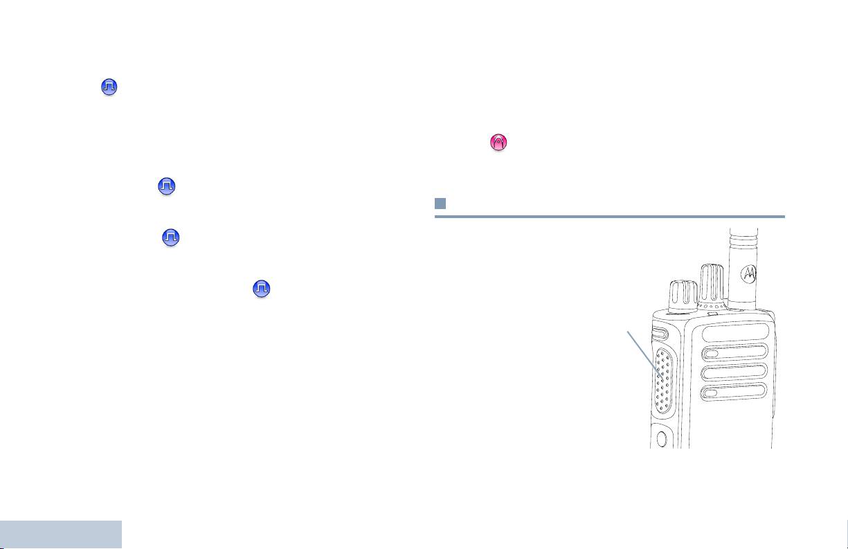
Push-To-Talk (PTT) Button
Telemetry Control – Controls the Output Pin on a local or
The PTT button on the
remote radio.
side of the radio serves
two basic purposes:
Transmit Interrupt Remote Dekey – Stops an ongoing
• While a call is in
interruptible call to free the channel.
progress, the PTT
PTT Button
Voice Announcement On/Off – Toggles Voice Announcement
button allows the radio
on or off.
to transmit to other
radios in the call.
Voice Operating Transmission (VOX) – Toggles VOX on or
off.
Press and hold down
PTT button to talk.
Zone – Allows selection from a list of zones.
Release the PTT
button to listen.
Battery Strength – Indicates battery strength via the LED
Identifying Radio Controls
Indicator.
The microphone is
activated when the PTT button is pressed.
* Not applicable in Capacity Plus
‡
Not applicable in Linked Capacity Plus
8
English
NKP_EMEA.book Page 9 Monday, July 2, 2012 3:50 PM
• While a call is not in progress, the PTT button is used to make
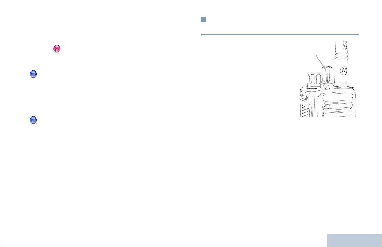
Switching Between Conventional Analog
a new call (see Making a Radio Call on page 18).
and Digital Mode
Identifying Radio Controls
Depending on programming, if the Talk Permit Tone or the PTT
Each channel in your radio
Sidetone is enabled, wait until the short alert tone ends
Channel Selector Knob
can be configured as a
before talking.
conventional analog or
conventional digital channel.
During a call, if the Channel Free Indication feature is
Use the Channel Selector
enabled on your radio (programmed by your dealer), you
Knob to switch between an
hear a short alert tone the moment the target radio (the
analog or a digital channel.
radio that is receiving your call) releases the PTT button,
When switching from digital
indicating the channel is free for you to respond.
to analog mode, certain
features are unavailable.
You will also hear a continuous talk prohibit tone, if your
Your radio also has features available in both analog and digital
call is interrupted, indicating that you should release the
mode. However, the minor differences in the way each feature
PTT button, for example when the radio receives an
works does NOT affect the performance of your radio.
Emergency Call.
NOTE: Your radio also switches between digital and analog
modes during a dual mode scan (see Scan on
page 24).
9
English

NKP_EMEA.book Page 10 Monday, July 2, 2012 3:50 PM
You cannot manually add or delete an entry to the roam list.
IP Site Connect
Check with your dealer or system administrator for more
This feature allows your radio to extend conventional
information.
communication beyond the reach of a single site, by connecting
to different available sites which are connected via an Internet
Capacity Plus
Protocol (IP) network.
When the radio moves out of range from one site and into the
Capacity Plus is a single-site trunking configuration of the
range of another, it connects to the new site's repeater to send
MOTOTRBO radio system, which uses a pool of channels to
or receive calls/data transmissions. Depending on your settings,
support hundreds of users and up to 254 Groups. This feature
this is done automatically or manually.
allows your radio to efficiently utilize the available number of
If the radio is set to do this automatically, it scans through all
programmed channels while in Repeater Mode.
available sites when the signal from the current site is weak or
Icons of features not applicable to Capacity Plus are not
when the radio is unable to detect any signal from the current
available in the menu. You hear a negative indicator tone if you
site. It then locks on to the repeater with the strongest Received
try to access a feature not applicable to Capacity Plus via a
Signal Strength Indicator (RSSI) value.
programmable button press.
In a manual site search, the radio searches for the next site in
Your radio also has features that are available in conventional
the roam list that is currently in range (but which may not have
digital mode, IP Site Connect, Capacity Plus and Linked
the strongest signal) and locks on to it.
Capacity Plus. However, the minor differences in the way each
feature works does NOT affect the performance of your radio.
NOTE: Each channel can only have either Scan or Roam
enabled, not both at the same time.
Check with your dealer or system administrator for more
information on this configuration.
Channels with this feature enabled can be added to a particular
roam list. The radio searches the channel(s) in the roam list
during the automatic roam operation to locate the best site.
Identifying Radio Controls
A roam list supports a maximum of 16 channels (including the
Selected Channel).
10
English

NKP_EMEA.book Page 11 Monday, July 2, 2012 3:50 PM
NOTE: You cannot manually add or delete an entry to the roam
Linked Capacity Plus
list. Check with your dealer or system administrator for
more information.
Identifying Radio Controls
Linked Capacity Plus is a multi-site multi-channel trunking
configuration of the MOTOTRBO radio system, combining the
Similar to Capacity Plus, icons of features not applicable to
best of both Capacity Plus and IP Site Connect configurations.
Linked Capacity Plus are not available in the menu. You hear a
negative indicator tone if you try to access a feature not
Linked Capacity Plus allows your radio to extend trunking
applicable to Linked Capacity Plus via a programmable button
communication beyond the reach of a single site, by connecting
press.
to different available sites which are connected via an Internet
Protocol (IP) network. It also provides an increase in capacity by
Check with your dealer or system administrator for more
efficiently utilizing the combined available number of
information on this configuration.
programmed channels supported by each of the available sites.
When the radio moves out of range from one site and into the
range of another, it connects to the new site's repeater to send
or receive calls/data transmissions. Depending on your settings,
this is done automatically or manually.
If the radio is set to do this automatically, it scans through all
available sites when the signal from the current site is weak or
when the radio is unable to detect any signal from the current
site. It then locks on to the repeater with the strongest Received
Signal Strength Indicator (RSSI) value.
In a manual site search, the radio searches for the next site in
the roam list that is currently in range (but which may not have
the strongest signal) and locks on to it.
Any channel with Linked Capacity Plus enabled can be added
to a particular roam list. The radio searches these channels
during the automatic roam operation to locate the best site.
11
English
NKP_EMEA.book Page 12 Monday, July 2, 2012 3:50 PM
Double blinking green – Radio is receiving a privacy-enabled
Identifying Status Indicators
call or data .
Your radio indicates its operational status through the following:
Solid yellow – Radio is monitoring a conventional channel.
LED Indicator . . . . . . . . . . . . . . . . . . . . . . . . . . . . . . . page 12
Also indicates fair battery charge when Battery Strength button
is pressed.
Audio Tones . . . . . . . . . . . . . . . . . . . . . . . . . . . . . . . . page 13
Indicator Tones . . . . . . . . . . . . . . . . . . . . . . . . . . . . . . page 13
Blinking yellow – Radio is scanning for activity or receiving a
Call Alert, or all local Linked Capacity Plus channels are busy.
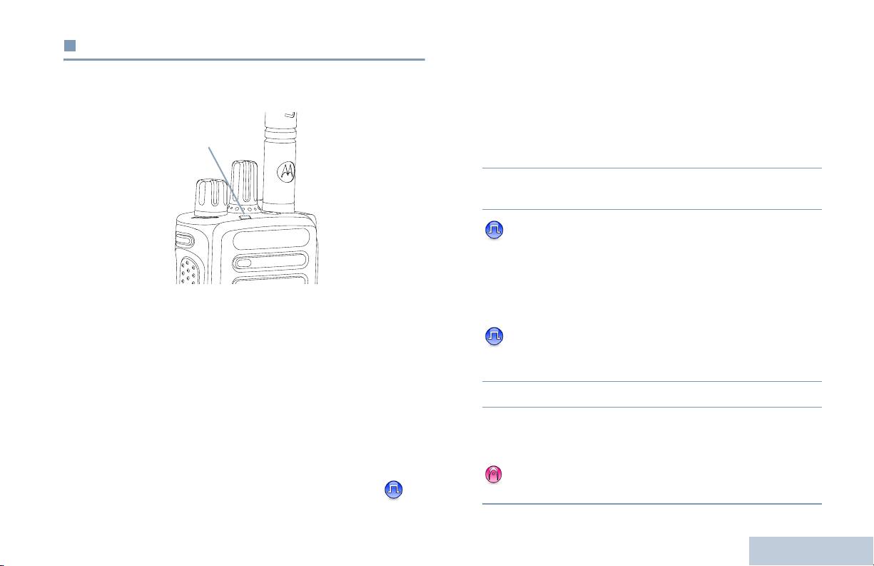
LED Indicator
Double blinking yellow – Radio is no longer connected to the
repeater while in Capacity Plus or Linked Capacity Plus, all
The LED indicator shows the
LED Indicator
Capacity Plus channels or Linked Capacity Plus channels are
operational status of your radio.
currently busy, Auto Roaming is enabled, radio is actively
searching for a new site. Also indicates radio has yet to respond
Blinking red – Radio is
to a group call alert, or radio is locked.
transmitting at low battery
condition, receiving an
emergency transmission or has
NOTE: While in conventional mode, when the LED blinks
failed the self-test upon
green, it indicates the radio detects activity over the air.
powering up.
Due to the nature of the digital protocol, this activity
Solid green – Radio is
may or may not affect the radio's programmed
powering up, or transmitting.
channel.
Also indicates full charge of the
For Capacity Plus and Linked Capacity Plus, there is
battery when Battery Strength
no LED indication when the radio is detecting activity
button is pressed.
over the air.
Blinking green – Radio is
Identifying Status Indicators
receiving a non-privacy-
enabled call or data, or
detecting activity over the air.
12
English
NKP_EMEA.book Page 13 Monday, July 2, 2012 3:50 PM
Indicator Tones
Audio Tones
Identifying Status Indicators
Alert tones provide you with audible indications of the radio’s
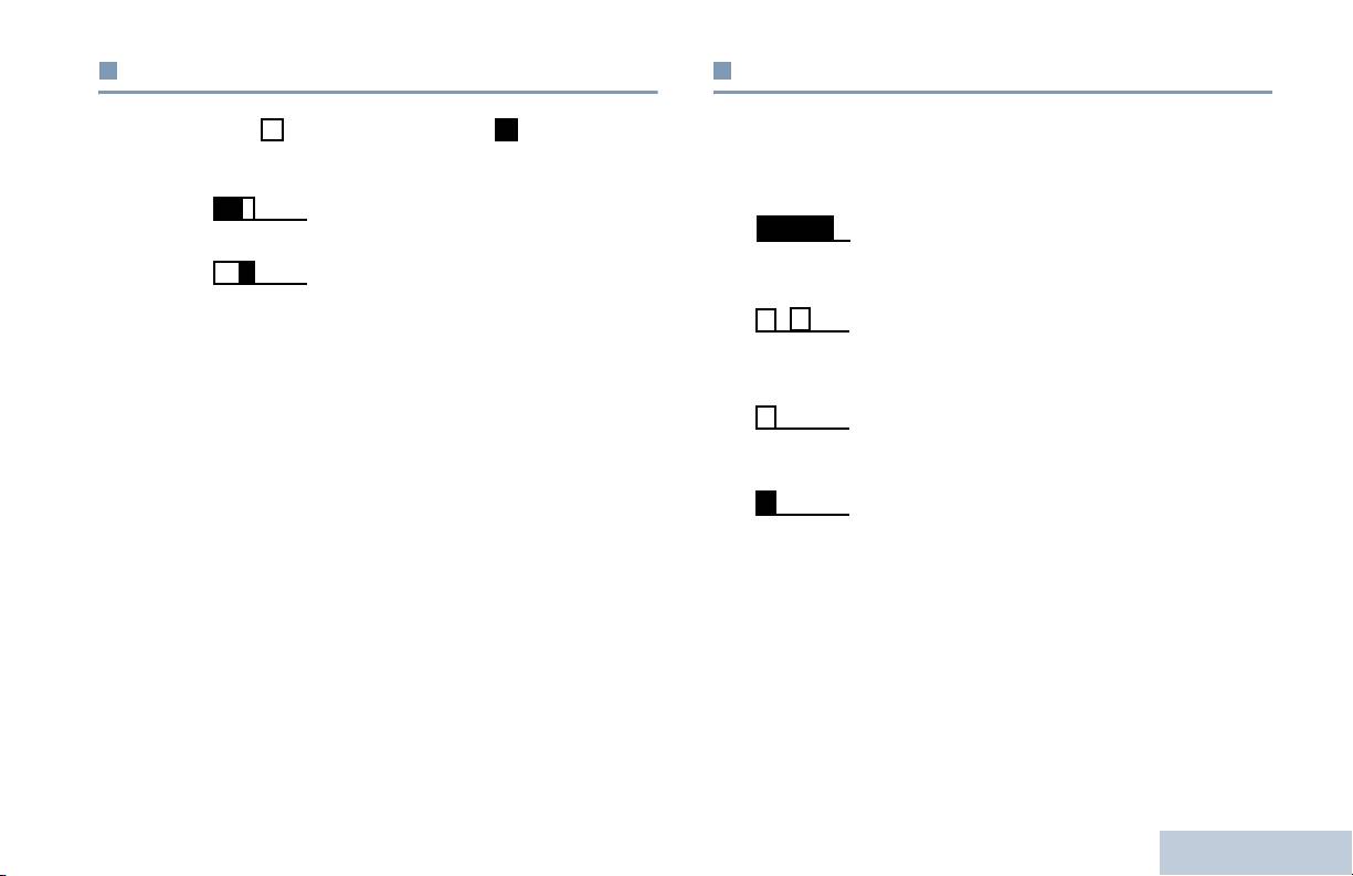
High pitched tone Low pitched tone
status or the radio’s response to data received.
Positive Indicator Tone
Continuous Tone A monotone sound. Sounds
continuously until termination.
Negative Indicator Tone
Periodic Tone Sounds periodically depending on the
duration set by the radio. Tone starts,
stops, and repeats itself.
Repetitive Tone A single tone that repeats itself until it is
terminated by the user.
Momentary Tone Sounds only once for a short period of
time defined by the radio.
13
English
NKP_EMEA.book Page 14 Monday, July 2, 2012 3:50 PM
You hear a negative indicator tone, indicating the radio has
Receiving and Making Calls
switched from Zone 2 to Zone 1.
Once you understand how your MOTOTRBO Portable is
configured, you are ready to use your radio.
Selecting a Channel
Use this navigation guide to familiarize yourself with the basic
Transmissions are sent and received on a channel. Depending
Call features:
on your radio's configuration, each channel may have been
Selecting a Zone . . . . . . . . . . . . . . . . . . . . . . . . . . . . . page 14
programmed differently to support different groups of users or
Selecting a Radio Channel, Subscriber ID,
supplied with different features. After selecting the required
or Group ID . . . . . . . . . . . . . . . . . . . . . . . . . . . . . . . page 14
zone, select the channel you require to transmit or receive on.
Receiving and Responding to a Radio Call. . . . . . . . . page 15
Making a Radio Call . . . . . . . . . . . . . . . . . . . . . . . . . . page 18
Stopping a Radio Call . . . . . . . . . . . . . . . . . . . . . . . . . page 21
Talkaround . . . . . . . . . . . . . . . . . . . . . . . . . . . . . . . . . page 21
Monitoring Features . . . . . . . . . . . . . . . . . . . . . . . . . . page 22
Selecting a Zone
A zone is a group of channels. Your radio supports up to 32
channels and 2 zones, with a maximum of 16 channels per
zone.
Procedure:
Procedure:
1 Press the programmed Zone button.
Turn the Channel Selector Knob to select the channel with
Receiving and Making Calls
the active group alias or ID.
2 You hear a positive indicator tone, indicating the radio has
switched from Zone 1 to Zone 2.
OR
14
English
NKP_EMEA.book Page 15 Monday, July 2, 2012 3:50 PM
Receiving and Responding to a Radio Call
Receiving and Responding to a Group Call
To receive a call made to a group of users, your radio must be
Receiving and Making Calls
Once the channel, subscriber ID, or group ID is set, you can
configured as part of that group.
proceed to receive and respond to calls.
Procedure:
LED Indicator
1 The LED blinks green. Your radio unmutes and the incoming
call sounds through the radio's speaker.
2 To respond, hold the radio vertically 1 to 2 inches (2.5 to 5.0
cm) from your mouth.
3 If the Channel Free Indication feature is enabled, you
hear a short alert tone the moment the transmitting radio
releases the PTT button, indicating the channel is free for
you to respond.
The LED lights up solid green while the radio is transmitting and
Press the PTT button to respond to the call.
OR
blinks when the radio is receiving.
NOTE: The LED lights up solid green while the radio is
If the Voice Interrupt feature is enabled, press the PTT
transmitting and double blinks green when the radio is
button to stop the current call from the transmitting radio and
receiving a privacy-enabled call.
free the channel for you to talk/respond.
4 The LED lights up solid green.
To unscramble a privacy-enabled call, your radio
must have the same Privacy Key, OR the same Key
5 Wait for the Talk Permit Tone to finish (if enabled) and speak
Value and Key ID (programmed by your dealer) as
clearly into the microphone.
the transmitting radio (the radio you are receiving
OR
the call from).
Wait for the PTT Sidetone to finish (if enabled) and
See Privacy on page 31 for more information.
speak clearly into the microphone.
15
English

NKP_EMEA.book Page 16 Monday, July 2, 2012 3:50 PM
6 Release the PTT button to listen.
4 Press the PTT button to respond to the call. The LED lights
up solid green.
7 If there is no voice activity for a predetermined period of
time, the call ends.
5 Wait for the Talk Permit Tone to finish (if enabled) and speak
clearly into the microphone.
See Making a Group Call on page 18 for details on making a
6 Release the PTT button to listen.
Group Call.
7 If there is no voice activity for a predetermined period of
Receiving and Responding to a Private Call
time, the call ends.
A Private Call is a call from an individual radio to another
8 You hear a short tone.
individual radio.
See Making a Private Call on page 19 for details on making a
Procedure:
Private Call.
When you receive a Private Call:
1 The LED blinks green. Your radio unmutes and the incoming
call sounds through the radio's speaker.
2 To respond, hold the radio vertically 1 to 2 inches (2.5 to 5.0
cm) from your mouth.
3 If the Channel Free Indication feature is enabled, you hear a
short alert tone the moment the transmitting radio releases
the PTT button, indicating the channel is free for you to
respond.
OR
If the Voice Interrupt feature is enabled, press the PTT
Receiving and Making Calls
button to stop the current call from the transmitting radio and
free the channel for you to talk/respond.
16
English

NKP_EMEA.book Page 17 Monday, July 2, 2012 3:50 PM
See Making a Selective Call on page 19 for details on making
Receiving and Responding to a Selective Call
a Selective Call.
A Selective Call is a call from an individual radio to another
Receiving and Making Calls
individual radio. It is a Private Call on an analog system.
Receiving an All Call
Procedure:
An All Call is a call from an individual radio to every radio on the
channel. It is used to make important announcements requiring
When you receive a Selective Call:
the user’s full attention.
1 The LED blinks green.
Procedure:
2 Hold the radio vertically 1 to 2 inches (2.5 to 5.0 cm) from
When you receive an All Call:
your mouth. Your radio unmutes and the incoming call
1 A tone sounds and the LED blinks green. Your radio
sounds through the radio's speaker.
unmutes and the incoming call sounds through the radio's
3 If the Channel Free Indication feature is enabled, you hear a
speaker.
short alert tone the moment the transmitting radio releases
2 If there is no voice activity for a predetermined period of
the PTT button, indicating the channel is free for you to
time, the All Call ends. An All Call does not wait for a
respond.
predetermined period of time before ending.
4 Press the PTT button to respond to the call. The LED lights
If the Channel Free Indication feature is enabled, you
up solid green.
hear a short alert tone the moment the transmitting radio
5 Wait for the Talk Permit Tone to finish (if enabled) and speak
releases the PTT button, indicating the channel is now
clearly into the microphone.
available for use.
6 Release the PTT button to listen.
You cannot respond to an All Call.
7 If there is no voice activity for a predetermined period of
NOTE: The radio stops receiving the All Call if you switch to a
time, the call ends.
different channel while receiving the call.
During an All Call, you are not able to use any
8 You hear a short tone.
programmed button functions until the call ends.
17
English

NKP_EMEA.book Page 18 Monday, July 2, 2012 3:50 PM
Procedure:
Making a Radio Call
1 Select the channel with the active group alias or ID. See
After selecting your channel, you can select a subscriber alias
Selecting a Channel on page 14.
or ID, or group alias or ID by using:
OR
Press the programmed One Touch Access button.
• The Channel Selector Knob
2 Hold the radio vertically 1 to 2 inches (2.5 to 5.0 cm) from
• A programmed One Touch Access button
your mouth.
3 Press the PTT button to make the call. The LED lights up
NOTE: Your radio must have the Privacy feature enabled on
solid green.
the channel to send a privacy-enabled transmission.
Only target radios with the same Privacy Key OR the
4 Wait for the Talk Permit Tone to finish (if enabled) and speak
same Key Value and Key ID as your radio are able to
clearly into the microphone.
unscramble the transmission.
OR
See Privacy on page 31 for more information.
Wait for the PTT Sidetone to finish (if enabled) and
speak clearly into the microphone.
The One Touch Access feature allows you to make a
5 Release the PTT button to listen. When the target radio
Group or Private Call to a predefined ID easily. This
feature can be assigned to a short or long
responds, the LED blinks green.
programmable button press.You can ONLY have one
6 If the Channel Free Indication feature is enabled, you hear a
ID assigned to a One Touch Access button. Your
short alert tone the moment the target radio releases the
radio can have multiple One Touch Access buttons
PTT button, indicating the channel is free for you to respond.
programmed.
Press the PTT button to respond.
OR
Making a Call with the Channel Selector Knob
If there is no voice activity for a predetermined period of
Receiving and Making Calls
Making a Group Call
time, the call ends.
To make a call to a group of users, your radio must be
configured as part of that group.
18
English

NKP_EMEA.book Page 19 Monday, July 2, 2012 3:50 PM
4 Wait for the Talk Permit Tone to finish (if enabled) and speak
Making a Private Call
clearly into the microphone.
Receiving and Making Calls
While you can receive and/or respond to a Private Call initiated
5 Release the PTT button to listen. When the target radio
by an authorized individual radio, your radio
responds, the LED blinks green.
must be programmed for you to initiate a Private Call.
6 If the Channel Free Indication feature is enabled, you hear a
There are two types of Private Calls. The first type, where a
short alert tone the moment the target radio releases the
radio presence check is performed prior to setting up the call,
PTT button, indicating the channel is free for you to respond.
while the other sets up the call immediately.
Press the PTT button to respond.
Only one of these call types can be programmed to your radio
OR
by your dealer.
If there is no voice activity for a predetermined period of
time, the call ends.
You hear a negative indicator tone, when you make a Private
Call via the One Touch Access button or the Channel
7 You hear a short tone.
Selector Knob, if this feature is not enabled.
Use the Quick Text Message or Call Alert features to contact an
Making a Selective Call
individual radio. See Text Messaging Features on page 30 or
Just like a Private Call, while you can receive and/or respond to
Call Alert Operation on page 26 for more information.
a Selective Call initiated by an authorized individual radio, your
Procedure:
radio must be programmed for you to initiate a Selective Call.
1 Select the channel with the active group alias or ID. See
Procedure:
Selecting a Channel on page 14.
1 Select the channel with the active group alias or ID. See
OR
Selecting a Channel on page 14.
Press the programmed One Touch Access button.
2 Hold the radio vertically 1 to 2 inches (2.5 to 5.0 cm) from
2 Hold the radio vertically 1 to 2 inches (2.5 to 5.0 cm) from
your mouth.
your mouth.
3 Press the PTT button to make the call. The LED lights up
3 Press the PTT button to make the call. The LED lights up
solid green.
solid green.
19
English

NKP_EMEA.book Page 20 Monday, July 2, 2012 3:50 PM
4 Wait for the Talk Permit Tone to finish (if enabled) and speak
4 Wait for the Talk Permit Tone to finish (if enabled) and speak
clearly into the microphone.
clearly into the microphone.
OR
5 Release the PTT button to listen. When the target radio
responds, the LED blinks green.
Wait for the PTT Sidetone to finish (if enabled) and
speak clearly into the microphone.
6 If the Channel Free Indication feature is enabled, you hear a
short alert tone the moment the target radio releases the
Users on the channel cannot respond to an All Call.
PTT button, indicating the channel is free for you to respond.
Press the PTT button to respond.
OR
If there is no voice activity for a predetermined period of
time, the call ends.
7 You hear a short tone.
Making an All Call
This feature allows you to transmit to all users on the channel.
Your radio must be programmed to allow you to use this feature.
Procedure:
1 Select the channel with the active group alias or ID. See
Selecting a Channel on page 14.
2 Hold the radio vertically 1 to 2 inches (2.5 to 5.0 cm) from
your mouth.
3 Press the PTT button to make the call. The LED lights up
Receiving and Making Calls
solid green.
20
English

NKP_EMEA.book Page 21 Monday, July 2, 2012 3:50 PM
Talkaround
Stopping a Radio Call
Receiving and Making Calls
You can continue to communicate when your repeater is not
This feature allows you to stop an ongoing Group or Private Call
operating, or when your radio is out of the repeater’s range but
to free the channel for transmission. For example, when a radio
within talking range of other radios. This is called “talkaround”.
experiences a “stuck microphone” condition where the PTT
button is inadvertently pressed by the user.
NOTE: This feature is not applicable in Capacity Plus and
Linked Capacity Plus.
Your radio must be programmed to allow you to use this feature.
Procedure:
Procedure:
While on the required channel:
1 Press the programmed Repeater/Talkaround button.
1 Press the programmed Transmit Interrupt Remote Dekey
2 You hear a positive indicator tone, indicating the radio is in
button.
Talkaround mode.
2 Wait for acknowledgment.
OR
You hear a negative indicator tone, indicating the radio is in
3 The radio sounds a positive indicator tone, indicating that
Repeater mode.
the channel is now free.
OR
The Talkaround setting is retained even after powering down.
The radio sounds a negative indicator tone, indicating that
the radio is unable to free the channel.
Your radio sounds a negative indicator tone until you release
the PTT button, if it is transmitting an interruptible call that is
stopped via this feature. On an interrupted radio with a display,
the display shows
Call Interrupted
.
21
English

NKP_EMEA.book Page 22 Monday, July 2, 2012 3:50 PM
Monitoring Features
Permanent Monitor
Use the Permanent Monitor feature to continuously monitor a
Monitoring a Channel
selected channel for activity.
Use the Monitor feature to make sure a channel is free before
NOTE: This feature is not applicable in Capacity Plus and
transmitting.
Linked Capacity Plus.
NOTE: This feature is not applicable in Capacity Plus and
Procedure:
Linked Capacity Plus.
1 Press the programmed Permanent Monitor button.
Procedure:
2 Radio sounds alert tone, and the LED lights up solid yellow.
1 Press and hold the programmed Monitor button and listen
3 Press the programmed Permanent Monitor button to
for activity.
remove the radio from permanent monitor mode.
2 You hear radio activity or total silence, depending on how
4 Radio sounds an alert tone and the LED turns off.
your radio is programmed.
3 When you hear “white noise” (that is, the channel is free),
press the PTT button to talk and release it to listen. The LED
lights up solid yellow.
Receiving and Making Calls
22
English

NKP_EMEA.book Page 23 Monday, July 2, 2012 3:50 PM
Scan Lists
Advanced Features
Advanced Features
Scan lists are created and assigned to individual channels/
Use this navigation guide to learn more about advanced
groups. Your radio scans for voice activity by cycling through the
features available with your radio:
channel/group sequence specified in the scan list for the current
Scan Lists . . . . . . . . . . . . . . . . . . . . . . . . . . . . . . . . . . page 23
channel.
Scan . . . . . . . . . . . . . . . . . . . . . . . . . . . . . . . . . . . . . . page 24
Your radio supports up to 250 scan lists, with a maximum of 16
Call Indicator Settings . . . . . . . . . . . . . . . . . . . . . . . . . page 26
members in a list. Each scan list shall support a mixture of both
Call Alert Operation . . . . . . . . . . . . . . . . . . . . . . . . . . . page 26
analog and digital entries.
Emergency Operation . . . . . . . . . . . . . . . . . . . . . . . . . page 27
NOTE: This feature is not applicable in Capacity Plus and
Text Messaging Features . . . . . . . . . . . . . . . . . . . . . . page 30
Linked Capacity Plus.
Privacy. . . . . . . . . . . . . . . . . . . . . . . . . . . . . . . . . . . . . page 31
Multi-Site Controls . . . . . . . . . . . . . . . . . . . . . . . . . . . . page 32
Lone Worker . . . . . . . . . . . . . . . . . . . . . . . . . . . . . . . . page 33
Password Lock Features. . . . . . . . . . . . . . . . . . . . . . . page 33
Bluetooth . . . . . . . . . . . . . . . . . . . . . . . . . . . . . . . . . . . page 34
Utilities. . . . . . . . . . . . . . . . . . . . . . . . . . . . . . . . . . . . . page 36
23
English

NKP_EMEA.book Page 24 Monday, July 2, 2012 3:50 PM
Scan
Starting and Stopping Scan
Procedure:
When you start a scan, your radio cycles through the
programmed scan list for the current channel looking for voice
1 Press the programmed Scan button.
activity.
OR
Use the Channel Selector Knob to select a channel with
The LED blinks yellow.
Auto Scan enabled.
During a dual mode scan, if you are on a digital channel, and
2 When Scan is enabled, the LED blinks yellow and you hear
your radio locks onto an analog channel, it automatically
a positive indicator tone.
switches from digital mode to analog mode for the duration of
OR
the call. This is also true for the reverse.
When Scan is disabled, the LED turns off and you hear a
There are two types of scans:
negative indicator tone.
• Main Channel Scan (Manual): Your radio scans all the
channels/groups in your scan list. On entering scan, your
Responding to a Transmission During a Scan
radio may – depending on the settings – automatically start
During scanning, your radio stops on a channel/group where
on the last scanned “active” channel/group or on the channel
activity is detected. The radio stays on that channel for a
where scan was initiated.
programmed time period known as “hang time”.
• Auto Scan (Automatic): Your radio automatically starts
Procedure:
scanning when you select a channel/group that has Auto
Scan enabled.
1 Hold the radio vertically 1 to 2 inches (2.5 to 5.0 cm) from
NOTE: This feature is not applicable in Capacity Plus and
your mouth.
Linked Capacity Plus.
If the Channel Free Indication feature is enabled, you
hear a short alert tone the moment the transmitting radio
releases the PTT button, indicating the channel is free for
Advanced Features
you to respond.
24
English

NKP_EMEA.book Page 25 Monday, July 2, 2012 3:50 PM
2 Press the PTT button during hang time. The LED lights up
Restoring a Nuisance Channel
solid green.
Procedure:
Advanced Features
3 Wait for the Talk Permit Tone to finish (if enabled) and speak
To restore the deleted nuisance channel, do one of the
clearly into the microphone.
following:
OR
• Turn the radio off and power it on again, OR
Wait for the PTT Sidetone to finish (if enabled) and
• Stop and restart a scan via the programmed Scan button, OR
speak clearly into the microphone.
• Change the channel via the Channel Selector Knob.
4 Release the PTT button to listen.
5 If you do not respond within the hang time, the radio returns
to scanning other channels/groups.
Vote Scan
Vote Scan provides you with wide area coverage in areas where
Deleting a Nuisance Channel
there are multiple base stations transmitting identical
If a channel continually generates unwanted calls or noise
information on different analog channels.
(termed a “nuisance” channel), you can temporarily remove the
Your radio scans analog channels of multiple base stations and
unwanted channel from the scan list.
performs a voting process to select the strongest received
This capability does not apply to the channel designated as the
signal. Once that is established, your radio unmutes to
Selected Channel.
transmissions from that base station.
Procedure:
The LED blinks yellow during the Vote Scan operation.
1 When your radio “locks on to” an unwanted or nuisance
To respond to a transmission during a Vote Scan, follow the
channel, press the programmed Nuisance Channel Delete
same procedures as Responding to a Transmission During a
button until you hear a tone.
Scan on page 24.
2 Release the Nuisance Channel Delete button. The
nuisance channel is deleted.
25
English

NKP_EMEA.book Page 26 Monday, July 2, 2012 3:50 PM
Call Indicator Settings
Making a Call Alert with the One Touch Access
Button
You can turn on or off the ringing tones for a received Private
Call (see Turning Radio Tones/Alerts On or Off on page 37).
Procedure:
1 Press the programmed One Touch Access button to make
Escalating Alarm Tone Volume
a Call Alert to the predefined ID.
Your radio can be programmed by your dealer to continually
2 The LED lights up solid green when your radio is sending
alert you when a radio call remains unanswered. This is done
the Call Alert.
by automatically increasing the alarm tone volume over time.
3 If the Call Alert acknowledgement is received, two chirps
This feature is known as Escalert.
sound.
OR
Call Alert Operation
If the Call Alert acknowledgement is not received, a
low-pitched tone sounds.
Call Alert paging enables you to alert a specific radio user to call
you back when they are able to do so. This feature is accessible
via a programmed One Touch Access button.
Receiving and Responding to a Call Alert
Procedure:
When you receive a Call Alert page:
1 You hear a repetitive tone. The LED blinks yellow.
2 Press the PTT button within four (4) seconds of receiving a
Advanced Features
Call Alert page to respond to the Private Call.
26
English

NKP_EMEA.book Page 27 Monday, July 2, 2012 3:50 PM
In addition, each alarm has the following types:
Emergency Operation
• Regular – Radio transmits an alarm signal and shows audio
Advanced Features
An Emergency Alarm is used to indicate a critical situation. You
and/or visual indicators.
are able to initiate an Emergency at any time, in any state, even
• Silent – Radio transmits an alarm signal without any audio or
when there is activity on the current channel.
visual indicators. Radio receives calls without any sound
Your dealer can set the duration of a button press for the
through the radio’s speaker, until you press the PTT button to
programmed Emergency button, except for long press, which is
initiate the call.
similar with all other buttons:
• Silent with Voice – Radio transmits an alarm signal without
• Short press – Between 0.05 seconds and 0.75 seconds
any audio or visual indicators, but allow incoming calls to
sound through the radio’s speaker.
• Long press – Between 1.00 second and 3.75 seconds
Only one of the Emergency Alarms above can be assigned to
The Emergency button is assigned with the Emergency On/Off
the programmed Emergency button.
feature. Check with your dealer for the assigned operation of
the Emergency button.
Sending an Emergency Alarm
If short press the Emergency button is assigned to turn on the
This feature allows you to send an Emergency Alarm, a non-
Emergency mode, then long press the Emergency button is
voice signal, which triggers an alert indication on a group of
assigned to exit the Emergency mode.
radios.
If long press the Emergency button is assigned to turn on the
Procedure:
Emergency mode, then short press the Emergency button is
1 Press the programmed Emergency On button.
assigned to exit the Emergency mode.
2 The LED lights up solid green.
Your radio supports three Emergency Alarms:
3 When an Emergency Alarm acknowledgment is received,
• Emergency Alarm
the Emergency tone sounds. The LED blinks green.
OR
• Emergency Alarm with Call
If your radio does not receive an Emergency Alarm
• Emergency Alarm with Voice to Follow
27
English

NKP_EMEA.book Page 28 Monday, July 2, 2012 3:50 PM
acknowledgement, and after all retries have been
Wait for the PTT Sidetone to finish (if enabled) and
exhausted, a low-pitched tone sounds.
speak clearly into the microphone.
4 Radio exits the Emergency Alarm mode.
7 Release the PTT button to listen.
If your radio is set to Silent, it does not display any audio or
8 When the channel is free for you to respond, a short alert
visual indicators during Emergency mode.
tone sounds ( if the Channel Free Indication feature is
Sending an Emergency Alarm with Call
enabled). Press the PTT button to respond.
OR
This feature allows you to send an Emergency Alarm to a group
Once your call ends, press Emergency Off button to exit
of radios. Upon acknowledgement by a radio within the group,
the Emergency mode.
the group of radios can communicate over a programmed
Emergency channel.
If your radio is set to Silent, it does not display any audio or
visual indicators during Emergency mode, or allow any received
Procedure:
calls to sound through the radio’s speaker, until you press the
1 Press the programmed Emergency On button.
PTT button to initiate the call.
2 The LED lights up solid green.
If your radio is set to Silent with Voice, it does not display any
audio or visual indicators during Emergency mode, but allow
3 When an Emergency Alarm acknowledgment is received,
incoming calls to sound through the radio’s speaker. The
the Emergency tone sounds. The LED blinks green.
indicators only appear once you press the PTT button to initiate,
4 Hold the radio vertically 1 to 2 inches (2.5 to 5.0 cm) from
or respond to, the call.
your mouth.
Sending an Emergency Alarm with Voice to
5 Press the PTT button to make the call. The LED lights up
solid green.
Follow
Advanced Features
6 Wait for the Talk Permit Tone to finish (if enabled) and speak
This feature allows you to send an Emergency Alarm to a group
clearly into the microphone.
of radios. Your radio’s microphone is automatically activated,
OR
28
English

NKP_EMEA.book Page 29 Monday, July 2, 2012 3:50 PM
allowing you to communicate with the group of radios without
4 The radio automatically stops transmitting when:
pressing the PTT button.
Once the cycling duration between hot mic and receiving
Advanced Features
calls expires, if Emergency Cycle Mode is enabled.
This activated microphone state is also known as “hot mic”.
OR
If your radio has Emergency Cycle Mode enabled, repetitions of
Once the hot mic duration expires, if Emergency Cycle
hot mic and receiving period are made for a programmed
Mode is disabled.
duration.
5 To transmit again, press the PTT button.
NOTE: During Emergency Cycle Mode, received calls sound
OR
through the radio’s speaker.
Press the programmed Emergency Off button to exit the
Emergency mode.
If you press the PTT button during the programmed receiving
period, you will hear a prohibit tone, indicating that you should
If your radio is set to Silent, it does not display any audio or
release the PTT button. The radio ignores the PTT press and
visual indicators during Emergency mode, or allow any received
remains in Emergency mode.
calls to sound through the radio’s speaker, until the
NOTE: If you press the PTT button during hot mic, and
programmed hot mic transmission period is over, and you press
continue to press it after the hot mic duration expires,
the PTT button.
the radio continues to transmit until you release the
If your radio is set to Silent with Voice, it does not display any
PTT button.
audio or visual indicators during Emergency mode when you
Procedure:
are making the call with hot mic, but allow sound through the
radio’s speaker when the target radio responds after the
1 Press the programmed Emergency On button.
programmed hot mic transmission period is over. The indicators
2 The LED lights up solid green.
only appear when you press the PTT button.
3 Once a tone sounds, speak clearly into the microphone.
NOTE: If the Emergency Alarm request fails, the radio does
not retry to send the request, and enters the hot mic
When hot mic has been enabled, the radio automatically
state directly.
transmits without a PTT press until the hot mic duration
expires.
While transmitting, the LED lights up solid green.
29
English

NKP_EMEA.book Page 30 Monday, July 2, 2012 3:50 PM
Reinitiating an Emergency Mode
Text Messaging Features
NOTE: This feature is only applicable to the radio sending the
Emergency Alarm.
Sending a Quick Text Message
There are two instances where this can happen:
You can send Quick Text messages, programmed by your
• You change the channel while the radio is in Emergency
dealer, via the programmable button.
mode. This exits the Emergency mode. If Emergency Alarm is
enabled on this new channel, the radio reinitiates Emergency.
Procedure:
• You press the programmed Emergency On button during an
1 Press the programmed One Touch Access button to send
Emergency initiation/transmission state. This causes the
a predefined Quick Text message to a predefined ID.
radio to exit this state, and to reinitiate Emergency.
2 The LED lights up solid green.
Exiting an Emergency Mode
3 Two chirps indicate that the message is sent successfully.
NOTE: This feature is only applicable to the radio sending the
OR
Emergency Alarm.
A low-pitched tone indicates that the message cannot be
sent.
Your radio exits Emergency mode when one of the following
occurs:
• Emergency Alarm acknowledgement is received (for
Emergency Alarm only), OR
• An Emergency Exit Telegram is received, OR
• All retries to send the alarm have been exhausted, OR
• The Emergency Off button is pressed.
Advanced Features
NOTE: If your radio is powered off, it exits the Emergency
mode. The radio does not reinitiate the Emergency
mode automatically when it is turned on again.
30
English

NKP_EMEA.book Page 31 Monday, July 2, 2012 3:50 PM
The LED lights up solid green while the radio is transmitting and
Privacy
blinks green rapidly when the radio is receiving an ongoing
privacy-enabled transmission.
Advanced Features
If enabled, this feature helps to prevent eavesdropping by
unauthorized users on a channel by the use of a software-
NOTE: Some radio models may not offer this Privacy feature.
Check with your dealer or system administrator for
based scrambling solution. The signaling and user identification
more information.
portions of a transmission are not scrambled.
Procedure:
Your radio must have privacy enabled on the channel to send a
Press the programmed Privacy button to toggle privacy on or
privacy-enabled transmission, although this is not a necessary
off.
requirement for receiving a transmission. While on a privacy-
enabled channel, the radio is still able to receive clear
(unscrambled) transmissions.
Your radio supports two types of privacy:
• Basic Privacy
• Enhanced Privacy
Only ONE of the privacy types above can be assigned to the
radio.
To unscramble a privacy-enabled call or data transmission, your
radio must be programmed to have the same Privacy Key (for
Basic Privacy), OR the same Key Value and Key ID (for
Enhanced Privacy) as the transmitting radio.
If your radio receives a scrambled call that is of a different
Privacy Key, OR a different Key Value and Key ID, you will
either hear a garbled transmission (Basic Privacy) or nothing at
all (Enhanced Privacy).
31
English

NKP_EMEA.book Page 32 Monday, July 2, 2012 3:50 PM
Stopping an Automatic Site Search
Multi-Site Controls
When the radio is actively searching for a new site:
These features are applicable when your current radio channel
Procedure:
is part of an IP Site Connect or Linked Capacity Plus
configuration.
1 Press the programmed Site Lock On/Off button.
See IP Site Connect on page 10 and Linked Capacity Plus on
2 A tone sounds and the LED turns off.
page 11 for more details about these configurations.
Starting a Manual Site Search
Starting an Automatic Site Search
Procedure:
NOTE: The radio only scans for a new site if the current signal
is weak or when the radio is unable to detect any signal
1 Press the programmed Manual Site Roam button.
from the current site. If the RSSI value is strong, the
2 A tone sounds and the LED blinks green.
radio remains on the current site.
3 You hear a positive indicator tone and the LED turns off,
Procedure:
indicating the radio is locked on to a site.
1 Press the programmed Site Lock On/Off button.
OR
You hear a negative indicator tone and the LED turns off,
2 A tone sounds.
indicating the radio is unable to lock on to a site.
3 The LED blinks yellow rapidly when the radio is actively
searching for a new site, and turns off once the radio locks
on to a site.
The radio also performs an automatic site search (site is
unlocked) during a PTT button press or data transmission if
Advanced Features
the current channel, multi-site channel with an attached roam
list, is out of range.
32
English

NKP_EMEA.book Page 33 Monday, July 2, 2012 3:50 PM
Lone Worker
Password Lock Features
Advanced Features
This feature prompts an emergency to be raised if there is no
If enabled, this feature allows you to access your radio via
user activity, such as any radio button press or activation of the
password upon powering up. Use the Channel Selector Knob
channel selector, for a predefined time.
and the three Side Buttons to enter password (see Radio
Controls of page 6):
Following no user activity for a programmed duration, the radio
pre-warns the user via an audio indicator once the inactivity
• Channel Selector Knob positions 1 to 9 represent
timer expires.
digits 1 to 9, and position 10 represents digit 0.
If there is still no acknowledgment by the user before the
• Side Buttons 1 to 3 represent digits 1 to 3.
predefined reminder timer expires, the radio initiates an
Emergency Alarm.
Accessing the Radio from Password
Only one of the following Emergency Alarms is assigned to this
Procedure:
feature:
Power up the radio.
1 You hear a continuous tone.
• Emergency Alarm
• Emergency Alarm with Call
2 Use the Channel Selector Knob to enter the first digit of the
password.
• Emergency Alarm with Voice to Follow
3 Press Side Button 1, 2 or 3 to enter each digit of the
remaining three digits of the password. You hear a positive
The radio remains in the emergency state allowing voice
indicator tone for each Side Button press.
messages to proceed until action is taken. See Emergency
When the second digit of the password is entered, your
Operation on page 27 on ways to exit Emergency.
radio ignores any Channel Selector Knob position change.
NOTE: This feature is limited to radios with this function
4 When the last digit of the four-digit password is entered,
enabled. Check with your dealer or system
your radio automatically checks the validity of the password.
administrator for more information.
If the password is correct:
Your radio proceeds to power up. See Powering Up the
33
English

NKP_EMEA.book Page 34 Monday, July 2, 2012 3:50 PM
Radio on page 5.
Bluetooth
OR
If the password is incorrect:
This feature allows you to use your radio with a Bluetooth-
You hear a continuous tone. Repeat Steps 1 to 3.
enabled device (accessory) via a Bluetooth connection. Your
OR
radio supports both Motorola and COTS (Commercially
After the third incorrect password, your radio enters into
available Off-The-Shelf) Bluetooth-enabled devices.
locked state. A tone sounds and the LED double blinks
yellow.
Bluetooth operates within a range of 10 meters line of sight.
This is an unobstructed path between your radio and your
Your radio enters into locked state for 15 minutes, and responds
Bluetooth-enabled device.
to inputs from On/Off/Volume Control Knob.
It is not recommended that you leave your radio behind and
NOTE: The radio is unable to receive any call, including
expect your Bluetooth-enabled device to work with a high
emergency calls, in locked state.
degree of reliability when they are separated.
At the fringe areas of reception, both voice and tone quality will
Unlocking the Radio from Locked State
start to sound "garbled" or "broken". To correct this problem,
simply position your radio and Bluetooth-enabled device closer
Procedure:
to each other (within the 10-meter defined range) to re-establish
Wait for 15 minutes. Repeat Steps 1 to 4 in Accessing the
clear audio reception. Your radio’s Bluetooth function has a
Radio from Password on page 33.
maximum power of 2.5 mW (4 dBm) at the 10-meter range.
OR
Power up the radio, if you have powered down the radio during
Your radio can support up to 3 simultaneous Bluetooth
locked state:
connections with Bluetooth-enabled devices of unique types.
1 A tone sounds and the LED double blinks yellow.
For example, a headset, a scanner, and a PTT-Only Device
(POD). Multiple connections with Bluetooth-enabled devices of
2 Wait for 15 minutes. Repeat Steps 1 to 4 in Accessing the
the same type are not supported.
Radio from Password on page 33.
Advanced Features
Refer to your respective Bluetooth-enabled device’s user
Your radio restarts the 15 minutes timer for locked state when
manual for more details on your Bluetooth-enabled device’s full
you power up.
capabilities.
34
English

NKP_EMEA.book Page 35 Monday, July 2, 2012 3:50 PM
Finding and Connecting to a Bluetooth Device
Disconnecting from a Bluetooth Device
Procedure:
Procedure:
Advanced Features
Turn on your Bluetooth-enabled device and place it in pairing
1 Press the programmed Bluetooth Disconnect button.
mode. Refer to respective Bluetooth-enabled device’s user
2 A positive indicator tone sounds when disconnected.
manual.
1 On your radio, press the programmed Bluetooth Connect
button.
Switching Audio Route
You can toggle audio routing between internal radio speaker
2 A tone sounds and LED blinks yellow.
and external Bluetooth-enabled accessory.
3 Your Bluetooth-enabled device may require additional steps
Procedure:
to complete the pairing. Refer to respective Bluetooth-
enabled device’s user manual.
1 Press the programmed Bluetooth Audio Switch button.
4 If successful, a positive tone sounds.
2 A tone sounds when the audio route has switched.
OR
If unsuccessful, a negative indicator tone sounds.
Do not turn off your Bluetooth-enabled device during the finding
and connecting operation as this cancels the operation.
Your radio connects to the Bluetooth-enabled device within
range with either the strongest signal strength, or to one which it
has connected to before in a prior session.
NOTE: A pin code may be required to be programmed in your
radio before it can pair with some devices. Contact
your dealer for more information.
35
English

NKP_EMEA.book Page 36 Monday, July 2, 2012 3:50 PM
Procedure:
Utilities
1 Press the programmed Power Level button.
Setting the Squelch Level
2 You hear a positive indicator tone, indicating the radio is
transmitting at low power.
You can adjust your radio's squelch level to filter out unwanted
OR
calls with low signal strength or channels that have a higher
You hear a negative indicator tone, indicating the radio is
than normal background noise.
transmitting at high power.
Settings: Normal is the default. Tight filters out (unwanted)
calls and/or background noise. However, calls from remote
Turning the Option Board Feature(s) On or Off
locations may also be filtered out.
A channel can support up to 6 option board features. Refer to
Procedure:
your dealer or system administrator for more information.
1 Press the programmed Squelch button.
Procedure:
Press the programmed Option Board Feature button to toggle
2 You hear a positive indicator tone, indicating the radio is
the feature on or off.
operating in tight squelch.
OR
Turning the Voice Operating Transmission (VOX)
You hear a negative indicator tone, indicating the radio is
Feature On or Off
operating in normal squelch.
This feature allows you to initiate a hands-free voice activated
call on a programmed channel. The radio automatically
Setting the Power Level
transmits, for a programmed period, whenever the microphone
You can toggle your radio’s power setting between high or low
on the VOX-capable accessory detects voice.
for each channel.
Pressing the PTT button during radio operation disables VOX.
Settings: High enables communication with radios located at a
Advanced Features
To re-enable VOX, do one of the following:
considerable distance from you. Low enables communication
with radios in closer proximity.
• Turn the radio off and power it on again, OR
36
English

NKP_EMEA.book Page 37 Monday, July 2, 2012 3:50 PM
• Change the channel via the Channel Selector Knob, OR
Checking the Battery Strength
• Follow the procedure below.
You can check how much battery power you have left.
Advanced Features
NOTE: Turning this feature on or off is limited to radios with
Settings: The LED Indicator in solid yellow indicates fair battery
this function enabled. Check with your dealer or system
charge while solid green indicates full charge of the battery.
administrator for more information.
See also LED Indicator on page 12.
Procedure:
Procedure:
Press the programmed VOX button to toggle the feature on or
Press the programmed Battery Strength button to view the
off.
battery strength via the LED Indicator.
If the Talk Permit Tone feature is enabled, use a trigger word to
initiate the call. Wait for the Talk Permit Tone to finish before
Voice Announcement
speaking clearly into the microphone.
This feature enables the radio to audibly indicate the current
Zone or Channel the user has just assigned, or programmable
Turning Radio Tones/Alerts On or Off
button press. This audio indicator can be customized per
You can enable and disable all radio tones and alerts (except for
customer requirements. This is typically useful when the user is
the incoming Emergency alert tone) if needed.
in a difficult condition to read the content shown on the display.
Procedure:
Use the following features to toggle Voice Announcement on or
off.
1 Press the programmed All Tones/Alerts button.
Procedure:
2 You hear a positive indicator tone, indicating all tones and
alerts are on.
Press the programmed Voice Announcement button.
OR
You hear a negative indicator tone, indicating all tones and
alerts are off.
37
English

NKP_EMEA.book Page 38 Monday, July 2, 2012 3:50 PM
Intelligent Audio
Your radio automatically adjusts its audio volume to overcome
current background noise in the environment, inclusive of both
stationary and non-stationary noise sources. This feature is a
Receive-only feature and does not affect Transmit audio.
NOTE: This feature is not applicable during a Bluetooth
session.
Use the following features to toggle Intelligent Audio on or off.
Procedure:
Press the programmed Intelligent Audio button to toggle the
feature on or off.
GPS
Global Positioning System (GPS) is a satellite navigation
system that determines the radio’s precise location.
Procedure:
Press the programmed GPS button to toggle the feature on or
off.
Advanced Features
38
English

NKP_EMEA.book Page 39 Monday, July 2, 2012 3:50 PM
The Capacity Warranty
Batteries and Chargers Warranty
The capacity warranty guarantees 80% of the rated capacity for the
Batteries and Chargers Warranty
warranty duration.
The Workmanship Warranty
Nickel Metal-Hydride (NiMH) or Lithium-Ion
The workmanship warranty guarantees against defects in
12 Months
(Li-lon) Batteries
workmanship under normal use and service.
IMPRES Batteries, When Used Exclusively
18 Months
All MOTOTRBO Batteries Two (2) Years
with IMPRES Chargers
IMPRES Chargers (Single-Unit and Multi-Unit,
Two (2) Years
Non-Display)
IMPRES Chargers (Multi-Unit with Display) One (1) Year
39
English

NKP_EMEA.book Page 40 Monday, July 2, 2012 3:50 PM
obligations or liability for additions or modifications to this warranty
Limited Warranty
unless made in writing and signed by an officer of MOTOROLA.
Unless made in a separate agreement between MOTOROLA and
the original end user purchaser, MOTOROLA does not warrant the
MOTOROLA COMMUNICATION PRODUCTS
installation, maintenance or service of the Product.
MOTOROLA cannot be responsible in any way for any ancillary
I. WHAT THIS WARRANTY COVERS AND FOR HOW
equipment not furnished by MOTOROLA which is attached to or
LONG:
used in connection with the Product, or for operation of the Product
MOTOROLA SOLUTIONS, INC. (“MOTOROLA”) warrants the
with any ancillary equipment, and all such equipment is expressly
MOTOROLA manufactured Communication Products listed below
excluded from this warranty. Because each system which may use
(“Product”) against defects in material and workmanship under
the Product is unique, MOTOROLA disclaims liability for range,
normal use and service for a period of time from the date of
coverage, or operation of the system as a whole under this
purchase as scheduled below:
warranty.
DP
Series Digital Portable Radios Two (2) Years
II. GENERAL PROVISIONS:
Product Accessories (Excluding
One (1) Year
Batteries and Chargers)
This warranty sets forth the full extent of MOTOROLA'S
responsibilities regarding the Product. Repair, replacement or
MOTOROLA, at its option, will at no charge either repair the
refund of the purchase price, at MOTOROLA’s option, is the
Product (with new or reconditioned parts), replace it (with a new or
exclusive remedy. THIS WARRANTY IS GIVEN IN LIEU OF ALL
reconditioned Product), or refund the purchase price of the Product
OTHER EXPRESS WARRANTIES. IMPLIED WARRANTIES,
during the warranty period provided it is returned in accordance
INCLUDING WITHOUT LIMITATION, IMPLIED WARRANTIES OF
with the terms of this warranty. Replaced parts or boards are
MERCHANTABILITY AND FITNESS FOR A PARTICULAR
warranted for the balance of the original applicable warranty period.
PURPOSE, ARE LIMITED TO THE DURATION OF THIS LIMITED
All replaced parts of Product shall become the property of
WARRANTY. IN NO EVENT SHALL MOTOROLA BE LIABLE FOR
MOTOROLA.
DAMAGES IN EXCESS OF THE PURCHASE PRICE OF THE
PRODUCT, FOR ANY LOSS OF USE, LOSS OF TIME,
This express limited warranty is extended by MOTOROLA to the
Limited Warranty
INCONVENIENCE, COMMERCIAL LOSS, LOST PROFITS OR
original end user purchaser only and is not assignable or
SAVINGS OR OTHER INCIDENTAL, SPECIAL OR
transferable to any other party. This is the complete warranty for the
CONSEQUENTIAL DAMAGES ARISING OUT OF THE USE OR
Product manufactured by MOTOROLA. MOTOROLA assumes no
40
English

NKP_EMEA.book Page 41 Monday, July 2, 2012 3:50 PM
INABILITY TO USE SUCH PRODUCT, TO THE FULL EXTENT
C)Defects or damage from improper testing, operation,
SUCH MAY BE DISCLAIMED BY LAW.
maintenance, installation, alteration, modification, or adjustment.
D)Breakage or damage to antennas unless caused directly by
Limited Warranty
III. STATE LAW RIGHTS:
defects in material workmanship.
E) A Product subjected to unauthorized Product modifications,
SOME STATES DO NOT ALLOW THE EXCLUSION OR
disassembles or repairs (including, without limitation, the addition
LIMITATION OF INCIDENTAL OR CONSEQUENTIAL DAMAGES
to the Product of non-MOTOROLA supplied equipment) which
OR LIMITATION ON HOW LONG AN IMPLIED WARRANTY
adversely affect performance of the Product or interfere with
LASTS, SO THE ABOVE LIMITATION OR EXCLUSIONS MAY
MOTOROLA's normal warranty inspection and testing of the
NOT APPLY.
Product to verify any warranty claim.
This warranty gives specific legal rights, and there may be other
F) Product which has had the serial number removed or made
rights which may vary from state to state.
illegible.
G)Rechargeable batteries if:
IV. HOW TO GET WARRANTY SERVICE:
(1) any of the seals on the battery enclosure of cells are broken
You must provide proof of purchase (bearing the date of purchase
or show evidence of tampering.
and Product item serial number) in order to receive warranty
(2) the damage or defect is caused by charging or using the
service and, also, deliver or send the Product item, transportation
battery in equipment or service other than the Product for which it
and insurance prepaid, to an authorized warranty service location.
is specified.
Warranty service will be provided by MOTOROLA through one of its
H)Freight costs to the repair depot.
authorized warranty service locations. If you first contact the
I) A Product which, due to illegal or unauthorized alteration of the
company which sold you the Product (e.g., dealer or
software/firmware in the Product, does not function in
communication service provider), it can facilitate your obtaining
accordance with MOTOROLA’s published specifications or the
warranty service.
FCC certification labeling in effect for the Product at the time the
Product was initially distributed from MOTOROLA.
V. WHAT THIS WARRANTY DOES NOT COVER:
J) Scratches or other cosmetic damage to Product surfaces that
A) Defects or damage resulting from use of the Product in other
does not affect the operation of the Product.
than its normal and customary manner.
K) Normal and customary wear and tear.
B) Defects or damage from misuse, accident, water, or neglect.
41
English

NKP_EMEA.book Page 42 Monday, July 2, 2012 3:50 PM
VI. PATENT AND SOFTWARE PROVISIONS:
MOTOROLA will have no liability with respect to any claim of patent
infringement which is based upon the combination of the Product or
MOTOROLA will defend, at its own expense, any suit brought
parts furnished hereunder with software, apparatus or devices not
against the end user purchaser to the extent that it is based on a
furnished by MOTOROLA, nor will MOTOROLA have any liability
claim that the Product or parts infringe a United States patent, and
for the use of ancillary equipment or software not furnished by
MOTOROLA will pay those costs and damages finally awarded
MOTOROLA which is attached to or used in connection with the
against the end user purchaser in any such suit which are
Product. The foregoing states the entire liability of MOTOROLA with
attributable to any such claim, but such defense and payments are
respect to infringement of patents by the Product or any parts
conditioned on the following:
thereof.
A) that MOTOROLA will be notified promptly in writing by such
Laws in the United States and other countries preserve for
purchaser of any notice of such claim;
MOTOROLA certain exclusive rights for copyrighted MOTOROLA
B) that MOTOROLA will have sole control of the defense of such
software such as the exclusive rights to reproduce in copies and
suit and all negotiations for its settlement or compromise; and
distribute copies of such MOTOROLA software. MOTOROLA
C)should the Product or parts become, or in MOTOROLA’s opinion
software may be used in only the Product in which the software was
be likely to become, the subject of a claim of infringement of a
originally embodied and such software in such Product may not be
United States patent, that such purchaser will permit
replaced, copied, distributed, modified in any way, or used to
MOTOROLA, at its option and expense, either to procure for
produce any derivative thereof. No other use including, without
such purchaser the right to continue using the Product or parts or
limitation, alteration, modification, reproduction, distribution, or
to replace or modify the same so that it becomes non-infringing
reverse engineering of such MOTOROLA software or exercise of
or to grant such purchaser a credit for the Product or parts as
rights in such MOTOROLA software is permitted. No license is
depreciated and accept its return. The depreciation will be an
granted by implication, estoppel or otherwise under MOTOROLA
equal amount per year over the lifetime of the Product or parts as
patent rights or copyrights.
established by MOTOROLA.
VII. GOVERNING LAW:
This Warranty is governed by the laws of the State of Illinois, U.S.A.
Limited Warranty
42
English

Bedienelemente und Anzeigen . . . . . . . . . . . . . . . . . . . 6
Inhalt
Die Bedienelemente . . . . . . . . . . . . . . . . . . . . . . . . . . . 6
Programmierbare Tasten . . . . . . . . . . . . . . . . . . . . . . . 7
Inhalt
Dieses Benutzerhandbuch enthält alle zur Verwendung der
Zuweisbare Funkgerätfunktionen . . . . . . . . . . . . . . . 7
MOTOTRBO Handfunkgeräteserie notwendigen
Zuweisbare Einstellungen oder
Anleitungen und Informationen.
Dienstprogrammfunktionen . . . . . . . . . . . . . . . . . . . . 8
Wichtige Sicherheitshinweise . . . . . . . . . . . . . . . . . . . iv
Sendetaste (PTT) . . . . . . . . . . . . . . . . . . . . . . . . . . . . . 8
Produktsicherheit und Einhaltung der
Umschalten zwischen analogem und digitalem
Strahlenschutzbedingungen . . . . . . . . . . . . . . . . . . . iv
Betriebsfunk . . . . . . . . . . . . . . . . . . . . . . . . . . . . . . . . 9
Softwareversion . . . . . . . . . . . . . . . . . . . . . . . . . . . . . . iv
IP-Site-Verbindung . . . . . . . . . . . . . . . . . . . . . . . . . . 10
Capacity Plus . . . . . . . . . . . . . . . . . . . . . . . . . . . . . . . 10
Copyright für die Computer-Software . . . . . . . . . . . . . .v
Linked Capacity Plus . . . . . . . . . . . . . . . . . . . . . . . . . 11
Sicherheitshinweise für die Handhabung . . . . . . . . . . vi
Identifizieren von Statusanzeigen . . . . . . . . . . . . . . . 12
Erste Schritte . . . . . . . . . . . . . . . . . . . . . . . . . . . . . . . . . .1
LED-Anzeige . . . . . . . . . . . . . . . . . . . . . . . . . . . . . . . 12
Informationen zu diesem Benutzerhandbuch . . . . . . . .1
Anzeigetöne . . . . . . . . . . . . . . . . . . . . . . . . . . . . . . . . 13
Von Ihrem Händler/Systemverwalter erhältliche
Töne . . . . . . . . . . . . . . . . . . . . . . . . . . . . . . . . . . . . . . 13
Informationen . . . . . . . . . . . . . . . . . . . . . . . . . . . . . . . .1
Durchführung und Empfang von Rufen . . . . . . . . . . 14
Inbetriebnahme Ihres Funkgeräts . . . . . . . . . . . . . . . . .2
Auswählen einer Zone . . . . . . . . . . . . . . . . . . . . . . . . 14
Laden des Akkus . . . . . . . . . . . . . . . . . . . . . . . . . . . . . .2
Auswählen eines Kanals . . . . . . . . . . . . . . . . . . . . . . 14
Anbringen des Akkus . . . . . . . . . . . . . . . . . . . . . . . . . . .3
Empfangen und Beantworten eines Rufs . . . . . . . . . . 15
Anbringen der Antenne . . . . . . . . . . . . . . . . . . . . . . . . .3
Empfangen und Beantworten eines
Anbringen des Gürtelclips . . . . . . . . . . . . . . . . . . . . . . .4
Gruppenrufs . . . . . . . . . . . . . . . . . . . . . . . . . . . . . . 15
Anbringen des Universal-buchsenabdeckung
Empfangen und Beantworten eines
(Staubkappe) . . . . . . . . . . . . . . . . . . . . . . . . . . . . . . . .4
Einzelrufs . . . . . . . . . . . . . . . . . . . . . . . . . . . . . . . . 16
Einschalten des Funkgeräts . . . . . . . . . . . . . . . . . . . . . .5
Empfangen und Beantworten eines
Einstellen der Lautstärke . . . . . . . . . . . . . . . . . . . . . . . .5
Selektivrufs . . . . . . . . . . . . . . . . . . . . . . . . . . . . . . . 17
Empfangen eines Rundumrufs . . . . . . . . . . . . . . . . 17
i
Deutsch

Durchführen eines Funkrufs . . . . . . . . . . . . . . . . . . . . 18
Notrufbetrieb . . . . . . . . . . . . . . . . . . . . . . . . . . . . . . . .27
Durchführen eines Rufs mit dem
Senden eines Notrufalarms . . . . . . . . . . . . . . . . . . .27
Kanalwahlschalter . . . . . . . . . . . . . . . . . . . . . . . . . . 18
Senden eines Notrufalarms mit Ruf . . . . . . . . . . . . .28
Durchführen eines Gruppenrufs . . . . . . . . . . . . . . 18
Senden eines Notrufalarms mit nachfolgendem
Durchführen eines Einzelrufs . . . . . . . . . . . . . . .19
Sprachruf . . . . . . . . . . . . . . . . . . . . . . . . . . . . . . . . .28
Durchführen eines Selektivrufs . . . . . . . . . . . . . . 19
Neuinitalisierung eines Notruf-Modus . . . . . . . . . . . .30
Durchführen eines Rundumrufs . . . . . . . . . . . . . . 20
Verlassen des Notruf-Modus . . . . . . . . . . . . . . . . . .30
Beenden eines Funkrufs . . . . . . . . . . . . . . . . . . . . . .21
Textnachrichtenfunktionen . . . . . . . . . . . . . . . . . . . . .30
Repeater umgehen . . . . . . . . . . . . . . . . . . . . . . . . . . . 21
Senden einer Quick Text-Nachricht . . . . . . . . . . . . .30
Überwachungsfunktionen (Monitoring) . . . . . . . . . . . . 22
Verschlüsselt . . . . . . . . . . . . . . . . . . . . . . . . . . . . . . . .31
Überwachen eines Kanals . . . . . . . . . . . . . . . . . . . . 22
Multi-Site-Bedienelemente . . . . . . . . . . . . . . . . . . . . .32
Dauer-Monitor . . . . . . . . . . . . . . . . . . . . . . . . . . . . . 22
Starten einer automatischen Site-Suche . . . . . . . . .32
Beenden einer automatischen Site-Suche . . . . . . . .32
Erweiterte Funktionen . . . . . . . . . . . . . . . . . . . . . . . . . 23
Starten einer manuellen Site-Suche . . . . . . . . . . . . .32
Scan-Listen . . . . . . . . . . . . . . . . . . . . . . . . . . . . . . . . .23
Alleinarbeiterschutz . . . . . . . . . . . . . . . . . . . . . . . . . . .33
Scan . . . . . . . . . . . . . . . . . . . . . . . . . . . . . . . . . . . . . .24
Passwort-geschützter Zugriff auf das Funkgerät . . . . .33
Starten und Stoppen von Scan . . . . . . . . . . . . . . . . 24
Passwort-geschützter Zugriff auf das
Beantworten eines Rufs während Suchlauf . . . . . . . 24
Funkgerät . . . . . . . . . . . . . . . . . . . . . . . . . . . . . . . . .33
Unterdrücken eines Störkanals . . . . . . . . . . . . . . . . 25
Entsperren des Funkgeräts . . . . . . . . . . . . . . . . . . .34
Wiederaufnahme eines Störkanals . . . . . . . . . . . . . 25
Bluetooth . . . . . . . . . . . . . . . . . . . . . . . . . . . . . . . . . . .34
Auswahlverfahren nach Signalgüte
Suchen und Anschließen eines
(Vote-Scan) . . . . . . . . . . . . . . . . . . . . . . . . . . . . . . . . 25
Bluetooth-Geräts . . . . . . . . . . . . . . . . . . . . . . . . . . .35
Rufanzeigeeinstellungen . . . . . . . . . . . . . . . . . . . . . . . 26
Abkoppeln eines Bluetooth-Geräts . . . . . . . . . . . . . .35
Zunehmende Alarmtonlautstärke . . . . . . . . . . . . . . . 26
Umschalten zwischen eingebautem und
Hinweiston . . . . . . . . . . . . . . . . . . . . . . . . . . . . . . . . . . 26
externem Lautsprecher (Audio-Routing) . . . . . . . . .35
Empfangen und Beantworten eines
Nützliche Funktionen/Dienstprogramme . . . . . . . . . . .36
Inhalt
Hinweistons . . . . . . . . . . . . . . . . . . . . . . . . . . . . . . . 26
Einstellen der Rauschsperre . . . . . . . . . . . . . . . . . .36
Senden eines Hinweistons mit der
Einstellen der Sendeleistung . . . . . . . . . . . . . . . . . .36
Schnellwahltaste . . . . . . . . . . . . . . . . . . . . . . . . . . . 26
ii
Deutsch

Ein- oder Ausschalten der
Zusatzkartenfunktion(en) . . . . . . . . . . . . . . . . . . . . .36
Ein- oder Ausschalten der VOX-Funktion
Inhalt
(sprachgesteuerte Übertragung) . . . . . . . . . . . . . . .36
Ein-/Ausschalten der Funkgerätruf-/
Hinweistöne . . . . . . . . . . . . . . . . . . . . . . . . . . . . . . .37
Überprüfen der Akkustärke . . . . . . . . . . . . . . . . . . . .37
Sprachansage . . . . . . . . . . . . . . . . . . . . . . . . . . . . .37
Intelligentes Audio . . . . . . . . . . . . . . . . . . . . . . . . . .38
GPS . . . . . . . . . . . . . . . . . . . . . . . . . . . . . . . . . . . . .38
Garantie für Akkus und Ladegeräte . . . . . . . . . . . . . .39
Eingeschränkte Garantie . . . . . . . . . . . . . . . . . . . . . . .40
iii
Deutsch

Wichtige Sicherheitshinweise
Softwareversion
Alle in den folgenden Abschnitten beschriebenen
Produktsicherheit und Einhaltung der
Funktionen werden von der Funkgeräte-Softwareversion
Strahlenschutzbedingungen
R02.04.00 unterstützt.
Bitte lesen Sie vor Inbetriebnahme dieses Produkts die
Weitere Informationen zu den unterstützten Funktionen
mit Ihrem Funkgerät gelieferte Beilage über
erhalten Sie von Ihrem Fachhändler oder
Produktsicherheit und Funkfrequenzstrahlung zum
Warnhinweis
sicheren Betrieb des Funkgeräts.
Systemadministrator.
ACHTUNG!
Zur Erfüllung der FCC/ICNIRP-HF-
Strahlenschutzbedingungen ist dieses Funkgerät
ausschließlich für den beruflichen Einsatz bestimmt.
Lesen Sie vor Verwendung dieses Produkts die mit Ihrem
Funkgerät gelieferte Beilage über Produktsicherheit und
Funkfrequenzstrahlung (Motorola-Druckschrift-Nr.
6864117B25), die nützliche Informationen zur Einhaltung
der Strahlenschutzbedingungen enthält.
Eine Auflistung der von Motorola genehmigten Antennen,
Akkus und anderen Zubehörteilen finden Sie auf
folgender Website:
Wichtige Sicherheitshinweise
http://www.motorolasolutions.com
iv
Deutsch

TM
Die in diesem Produkt eingebettete AMBE+2
Copyright für die Computer-Software
Sprachcodierungstechnologie ist durch geistiges Eigentum und
Copyright für die Computer-Software
Urheberrechte einschließlich Patentansprüche, Copyrights und
Die in diesem Handbuch beschriebenen Motorola-Produkte
Industriegeheimnisvorgaben von Digital Voice Systems, Inc.
werden zum Teil mit urheberrechtlich geschützten Motorola-
geschützt.
Software-Programmen ausgeliefert, die in Halbleiterspeichern
Die Nutzung dieser Sprachcodierungstechnologie wird
oder auf anderen Medien gespeichert sind. Nach den Gesetzen
ausschließlich in Verbindung mit der Nutzung dieser
der USA und anderer Staaten sind bestimmte exklusive Rechte
Kommunikationsausrüstung genehmigt. Benutzern dieser
an der urheberrechtlich geschützten Software, einschließlich
Technologie ist jeder Versuch, die Zielsprache/den Objektcode
aber nicht nur Rechte der Vervielfältigung, ausschließlich der
zu entkompilieren, analysieren (Reverse Engineering) oder auf
Firma Motorola vorbehalten. Demzufolge dürfen
jegliche andere Art in eine lesbare Form zu übertragen,
urheberrechtlich geschützte Motorola Software-Programme, die
ausdrücklich untersagt.
zusammen mit den in dem vorliegenden Handbuch
beschriebenen Produkten ausgeliefert werden, ohne die
U.S. Pat. Nr. 5,870,405, 5,826,222, 5,754,974, 5,701,390,
vorherige schriftliche Genehmigung von Motorola weder
5,715,365, 5,649,050, 5,630,011, 5,581,656, 5,517,511,
kopiert, reproduziert, modifiziert, analysiert (Reverse
5,491,772, 5,247,579, 5,226,084 und 5,195,166.
Engineering) noch in irgendeiner Weise weiter vertrieben
werden. Des Weiteren bedeutet der Erwerb von Motorola-
Produkten in keiner Weise den Erwerb einer Lizenz für die
mitgelieferten Produkte, die durch Schutzrechte oder
Schutzrechtsanmeldungen der Firma Motorola geschützt sind.
Der Käufer erhält mit dem Erwerb lediglich die normale
Berechtigung, das Produkt in der dafür vorgesehenen Form und
in rechtmäßiger Weise zu benutzen.
v
Deutsch

• Die Entlüftungsöffnung am Funkgerätgehäuse unter dem
Sicherheitshinweise für die
Akkukontakt ermöglicht den Druckausgleich im Funkgerät.
Stochern Sie nie in diese Öffnung, da dadurch ein Leckweg in
Handhabung
das Funkgerät entstehen kann, so dass das Funkgerät seine
Wasserdichtheit verlieren würde.
Das MOTOTRBO Digital-Handfunkgerät erfüllt die Bedingungen
der Schutzart IP57, d.h. es ist widrigen Einsatzbedingungen wie
• Die Entlüftungsöffnung darf auf keinen Fall blockiert oder
z.B. Untertauchen in Wasser gewachsen.
verdeckt werden, auch nicht mit einem Etikett.
• Wurde das Funkgerät in Wasser getaucht, ist es gut zu
• Stellen Sie sicher, dass die Entlüftungsöffnung nicht mit
schütteln, um es von eventuell im Lautsprechergitter und im
öligen Stoffen in Kontakt kommt.
Mikrofonanschluss befindlichem Wasser zu befreien. Dort
• Das Funkgerät mit ordnungsgemäß angebrachter Antenne ist
eingedrungenes Wasser könnte die Audioleistung verringern.
für eine Wasserdichtheit bis maximal einen (1) Meter und
• Wenn der Akkukontaktbereich des Funkgeräts mit Wasser in
maximal 30 Minuten ausgelegt. Bei Überschreiten der
Kontakt gekommen ist, sind die Akkukontakte am Funkgerät
maximalen Eintauchtiefe oder Eintauchdauer oder Gebrauch
und am Akku zu reinigen und zu trocknen, bevor der Akku am
des Funkgeräts ohne Antenne kann das Funkgerät
Funkgerät angebracht wird. Restfeuchtigkeit an den
beschädigt werden.
Kontakten könnte das Funkgerät kurzschließen.
• Reinigen Sie das Funkgerät nicht mit einem Hochdruckstrahl,
• Wenn das Funkgerät in eine korrodierende Flüssigkeit (z.B.
da dieser Druck für die vorgesehene Wasserdichtheit (d.h.
Salzwasser) getaucht wurde, ist es mit sauberem Süßwasser
Druck in 1 m Tiefe) zu hoch ist und eventuell Wasser in das
abzuspülen. Anschließend müssen Funkgerät und Akku
Funkgerät eindringen lässt.
abgetrocknet werden.
Das Funkgerät darf nicht zerlegt werden, da
• Verwenden Sie zum Reinigen der Außenflächen des
seine Dichtungen dadurch beschädigt werden
Funkgeräts eine verdünnte Lösung aus einem milden
könnten und es undicht werden könnte. Die
Spülmittel und frischem Wasser (d.h. ein Teelöffel Spülmittel
Wartung des Funkgeräts darf ausschließlich im
auf 4 Liter Wasser).
Wartungszentrum durchgeführt werden, das
Sicherheitshinweise für die Handhabung
zum Testen und Ersetzen der Dichtungen am
Funkgerät eingerichtet ist.
vi
Deutsch
Warnhinweis

Bei Funktionsmerkmalen, die im analogen und im digitalen Betrieb
Erste Schritte
verfügbar sind, wird kein Symbol angezeigt.
Weitere Informationen über Merkmale, die im Multi-Site-
Erste Schritte
Nehmen Sie sich bitte einen Augenblick Zeit für folgende
Betriebsfunk zur Verfügung stehen, finden Sie unter
Abschnitte:
IP-Site-Verbindung auf Seite 10.
Informationen zu diesem Benutzerhandbuch. . . . . . . . . . . Seite 1
Ausgewählte Funktionsmerkmale sind auch im
Von Ihrem Händler/Systemverwalter
Single-Site-Bündelfunkbetrieb für einzelne Sites, Capacity Plus,
erhältliche Informationen . . . . . . . . . . . . . . . . . . . . . . . . Seite 1
verfügbar. Weitere Angaben über Capacity Plus finden Sie auf
Seite 10.
Informationen zu diesem
Ausgewählte Merkmale stehen auch im Multi-Site-
Bündelfunkbetrieb Linked Capacity Plus zur Verfügung. Weitere
Benutzerhandbuch
Informationen über Linked Capacity Plus auf Seite 11.
Dieses Benutzerhandbuch enthält alle zur Verwendung der
Von Ihrem Händler/Systemverwalter
MOTOTRBO Handfunkgeräte ohne Display notwendigen
Informationen.
erhältliche Informationen
Es kann jedoch sein, dass Ihr Händler oder Systemverwalter Ihr
Für folgende Auskünfte setzen Sie sich bitte mit Ihrem
Funkgerät an Ihre speziellen Anforderungen und Bedürfnisse
Systemverwalter oder Händler in Verbindung:
angepasst hat. Für weitere Informationen setzen Sie sich bitte mit
Ihrem Systemverwalter oder Händler in Verbindung.
• Wurden voreingestellte Betriebsfunkkanäle bereits in das
Funkgerät einprogrammiert?
In dieser Veröffentlichung werden die nachstehenden Symbole
verwendet, um zwischen Funktionsmerkmalen ausschließlich im
• Welche Tasten wurden bereits zum Aufrufen anderer Funktionen
analogen Betriebsfunk bzw. ausschließlich im ditigalen
programmiert?
Betriebsfunk zu unterscheiden:
• Welche zusätzlichen Zubehörteile kommen Ihren Bedürfnissen
entgegen?
Bedeutet Funktionsmerkmal ausschließlich für
analogen Betriebsfunk.
• Wie sehen die besten Vorgehensweisen für die effektive Nutzung
von Funkgeräten aus?
Bedeutet Funktionsmerkmal ausschließlich für
digitalen Betriebsfunk.
• Welche Wartungsmaßnahmen können zu einer längeren
Lebensdauer von Funkgeräten beitragen?
1
Deutsch

Laden des Akkus
Inbetriebnahme Ihres Funkgeräts
Ihr Funkgerät wird für optimale Leistung mit einem von Motorola
Bauen Sie das Funkgerät wie im Folgenden beschrieben
zugelassenen Nickel-Metallhydrid- (NiMH) oder einem Lithium-
zusammen:
Ionen-Akku betrieben. Laden Sie Akkus ausschließlich in einem
Laden des Akkus . . . . . . . . . . . . . . . . . . . . . . . . . . . . . . . . Seite 2
Motorola-Ladegerät laut den Anweisungen im Handbuch für das
Anbringen des Akkus. . . . . . . . . . . . . . . . . . . . . . . . . . . . . Seite 3
Ladegerät auf, um eventuelle Schäden zu vermeiden und die
Anbringen der Antenne . . . . . . . . . . . . . . . . . . . . . . . . . . . Seite 3
Garantiebedingungen einzuhalten.
Anbringen des Gürtelclips . . . . . . . . . . . . . . . . . . . . . . . . . Seite 4
Um die optimale Leistung des Funkgeräts sicherzustellen, ist ein
Anbringen des Universal-buchsenabdeckung
neuer Akku vor dem Erstgebrauch 14 bis 16 Stunden aufzuladen.
(Staubkappe) . . . . . . . . . . . . . . . . . . . . . . . . . . . . . . . . . Seite 4
Einschalten des Funkgeräts. . . . . . . . . . . . . . . . . . . . . . . . Seite 5
WICHTIG: Für eine optimierte Batterielebensdauer und zum
Einstellen der Lautstärke . . . . . . . . . . . . . . . . . . . . . . . . . . Seite 5
Erhalten wertvoller Batteriedaten müssen IMPRES-
Akkus IMMER in einem IMPRES-Ladegerät geladen
werden. Für IMPRES-Akkus, die ausschließlich mit
IMPRES-Ladegeräten aufgeladen werden, wird die
Motorola Premium Standard-Akkugarantie um sechs
Monate verlängert.
Inbetriebnahme Ihres Funkgeräts
2
Deutsch

Anbringen des Akkus
Anbringen der Antenne
Richten Sie den Akku auf die Führung an der Rückseite des
Inbetriebnahme Ihres Funkgeräts
Schalten Sie das Funkgerät aus,
Funkgeräts aus. Setzen Sie den Akku fest auf und schieben Sie ihn
stecken Sie die Antenne in die Fassung
aufwärts, bis die Verriegelung einrastet. Schieben Sie die
und drehen Sie sie im Uhrzeigersinn.
Akkuverriegelung in die Sperrposition.
Zum Entfernen der Antenne drehen Sie
sie gegen den Uhrzeigersinn.
Zum Entfernen des
Akkus schalten Sie
das Funkgerät aus.
Schieben Sie die
Akkuverriegelung in
die gelöste Position
und schieben Sie
den Akku abwärts
aus der Führung
heraus.
3
Deutsch
Akku-
verriegelung
Muss eine Antenne ersetzt werden, ist sicherzustellen,
dass ausschließlich MOTOTRBO Antennen verwendet
werden. Die Verwendung anderer Antennen
verursacht Schäden am Funkgerät.
Warnhinweis
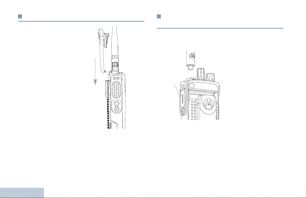
Anbringen des Gürtelclips
Anbringen des Universal-
buchsenabdeckung (Staubkappe)
Richten Sie die Aussparungen
Die Universalbuchse befindet sich auf der Antennenseite des
des Clips auf die am Akku aus
Funkgeräts. Sie wird zum Anschluss von MOTOTRBO Zubehör an
und drücken Sie den Clip bis
das Funkgerät verwendet.
zum hörbaren Einrasten nach
Stecken Sie das mit Haken
unten.
versehene Ende der
Abdeckung in die Ritzen
Zum Entfernen des Clips
oberhalb des
drücken Sie den
Universalanschlusses.
Gürtelclipauslöser vom Akku
Drücken Sie die Abdeckung
weg (mit Hilfe eines
nach unten, so dass der untere
Schlüssels ist das eventuell
Ansatz fest im HF-Anschluss
einfacher). Danach schieben
einrastet.
Sie den Clip aufwärts vom
Funkgerät weg.
Drehen Sie die Flügelschraube
im Uhrzeigersinn, um die
Abdeckung am Funkgerät zu
befestigen.
Zum Entfernen der Universalanschlussabdeckung drücken Sie in
Abwärtsrichtung auf die Abdeckung und drehen die Flügelschraube
gegen den Uhrzeigersinn.
Bringen Sie die Staubkappe wieder an, wenn die Universalbuchse
nicht mehr benutzt wird.
Inbetriebnahme Ihres Funkgeräts
4
Deutsch
Universal-
anschluss

Einschalten des Funkgeräts
Einstellen der Lautstärke
Inbetriebnahme Ihres Funkgeräts
Drehen Sie den Ein/Aus/
Zum Höherstellen der Lautstärke drehen Sie den Ein/Aus/
Lautstärkeregler im
Lautstärkeregler im Uhrzeigersinn.
Uhrzeigersinn, bis Sie ein
Klicken hören. Die LED
leuchtet grün.
Sie hören einen kurzen Ton,
der anzeigt, dass der
Einschalttest erfolgreich
durchgeführt wurde.
HINWEIS: Sind die
Funkgerätruf-/
Hinweistöne
deaktiviert, ertönt
beim Einschalten
kein Ton (siehe
Ein-/Ausschalten
der Funkgerätruf-/Hinweistöne auf Seite 37).
Zum Leiserstellen der Lautstärke drehen Sie den Regler gegen den
Uhrzeigersinn.
Wenn sich Ihr Funkgerät nicht einschalten lässt, prüfen Sie nach,
ob der Akku geladen und ordnungsgemäß eingelegt ist. Gelingt es
HINWEIS: Ihr Funkgerät kann auf eine Mindestlautstärke
trotzdem nicht, das Funkgerät einzuschalten, setzen Sie sich mit
programmiert werden. Die Lautstärke kann dann nicht
Ihrem Händler in Verbindung.
niedriger als diese einprogrammierte Mindestlautstärke
eingestellt werden. Für weitere Informationen setzen
Zum Ausschalten des Funkgeräts drehen Sie diesen Regler gegen
Sie sich bitte mit Ihrem Systemverwalter oder Händler
den Uhrzeigersinn, bis Sie ein Klicken hören.
in Verbindung.
5
Deutsch
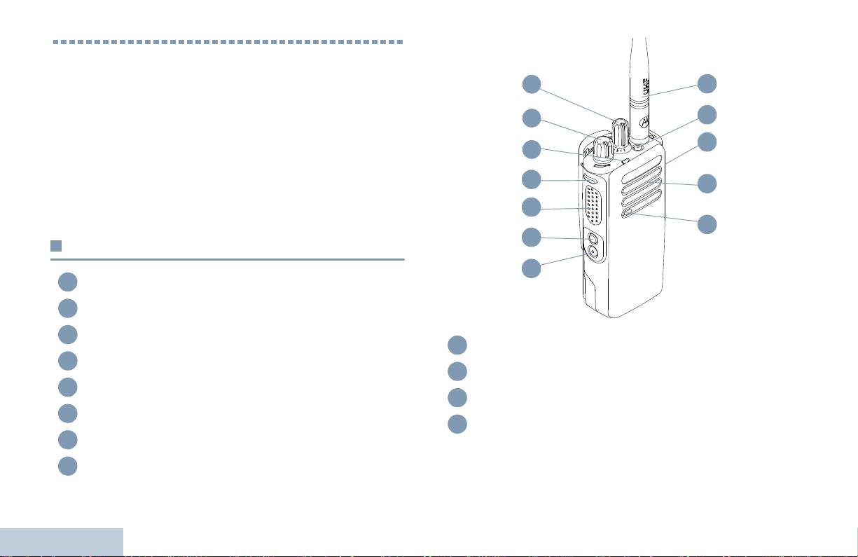
Bedienelemente und Anzeigen
Nehmen Sie sich bitte einen Augenblick Zeit für folgende
Abschnitte:
Die Bedienelemente. . . . . . . . . . . . . . . . . . . . . . . . . . . . . . Seite 6
Programmierbare Tasten . . . . . . . . . . . . . . . . . . . . . . . . . . Seite 7
Sendetaste (PTT). . . . . . . . . . . . . . . . . . . . . . . . . . . . . . . . Seite 8
Umschalten zwischen analogem und digitalem
Betriebsfunk . . . . . . . . . . . . . . . . . . . . . . . . . . . . . . . . . . Seite 9
IP-Site-Verbindung. . . . . . . . . . . . . . . . . . . . . . . . . . . . . . Seite 10
Capacity Plus . . . . . . . . . . . . . . . . . . . . . . . . . . . . . . . . . . Seite 10
Linked Capacity Plus . . . . . . . . . . . . . . . . . . . . . . . . . . . . .Seite 11
Die Bedienelemente
Kanalwahlschalter
Ein/Aus/Lautstärkeregler
LED-Anzeige
Seitentaste 1*
Sendetaste (PTT)
Seitentaste 2*
Seitentaste 3*
Bedienelemente und Anzeigen
Mikrofon
6
Deutsch
1
2
3
4
5
6
7
8
Lautsprecher
Universalanschluss für Zubehör
Notruftaste*
Antenne
* Diese Tasten können programmiert werden.
1
12
2
11
10
3
4
9
5
8
6
7
9
10
11
12

Sprachansage für Kanal – Sprachansage von Zonen- und
Programmierbare Tasten
Kanalnachrichten für den aktuellen Kanal. Diese Funktion ist nur
bei aktivierter Sprachansage verfügbar.
Bedienelemente und Anzeigen
Diese Tasten können von Ihrem Händler vorprogrammiert werden.
Sie dienen dann, je nachdem, wie lange sie gedrückt werden, zum
Notruf – Je nach Programmierung wird ein Notrufalarm oder ein
Direktzugriff auf verschiedene Funktionen oder auf
Notruf eingeleitet oder abgebrochen.
voreingestellte Kanäle/Gruppen:
Intell. Audio Ein/Aus – Schaltet (intelligentes) Smart-Audio ein
• Kurz drücken – Kurz drücken
bzw. aus.
• Lang drücken – Für die vorprogrammierte Zeitdauer gedrückt
‡
Manuelles Site-Roaming*
– Startet die manuelle Site-
halten
Suche.
• Halten – Taste gedrückt halten.
Mikrofon-AGC Ein/Aus – Schaltet die Verstärkungsautomatik
HINWEIS: Die vorprogrammierte Zeitdauer für einen Tastendruck
(AGC) des eingebauten Funkgerätmikrofons ein bzw. aus.
gilt für alle zuweisbaren Funkgerät-/
Während einer Bluetooth-Session ist diese Funktion nicht
Dienstprogrammfunktionen und Einstellungen. Weitere
verfügbar.
Informationen über die vorprogrammierte
Tastendruckdauer der Notruftaste finden Sie unter
Monitor – Überwacht einen gewählten Kanal auf Aktivität.
Notrufbetrieb auf Seite 27.
‡
Störkanal löschen*
– Entfernt unerwünschten Kanal (mit
Ausnahme des gewählten Kanals) vorübergehend aus der
Zuweisbare Funkgerätfunktionen
Scan-Liste. Mit dem gewählten Kanal ist die vom Benutzer
gewählte Zone/Kanal-Kombination gemeint, von der aus Scannen
TM
Bluetooth
Audio-Umschalttaste – Schaltet die Audioausgabe
gestartet wird.
auf den eingebauten Lautsprecher des Funkgeräts bzw. das
Schnellwahltaste –
Leitet einen vordefinierten Einzel- oder
Bluetooth-fähige Zubehör um.
Gruppenruf, einen Hinweiston oder eine Quick Text-Nachricht direkt
Bluetooth koppeln – Leitet eine Bluetooth-Gerätesuche und -
ein
Kopplung ein.
Zusatzkartenfunktion – Schaltet Zusatzkartenfunktion(en) für
Bluetooth abkoppeln – Beendet alle bestehenden Bluetooth-
Kanäle mit aktivierter Zusatzkarte ein oder aus.
Verbindungen zwischen Ihrem Funkgerät und Bluetooth-fähigen
Geräten.
Rufweiterleitung – Schaltet die Rufweiterleitung ein bzw. aus.
7
Deutsch
* In Capacity Plus nicht zutreffend
‡
In Linked Capacity Plus nicht verfügbar
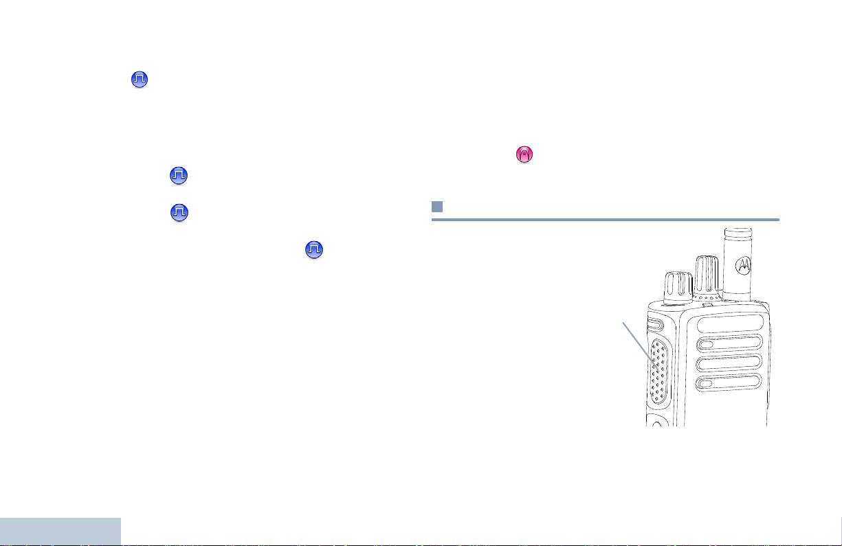
‡
Dauer-Monitor*
– Überwacht einen gewählten Kanal auf
Zuweisbare Einstellungen oder
sämtlichen Funkverkehr, bis die Funktion deaktiviert wird.
Dienstprogrammfunktionen
Verschlüsselt –
Schaltet Verschlüsselung ein oder aus.
Alle Töne/Hinweistöne – Schaltet alle Töne und Hinweistöne ein
‡
Repeater/Repeater umgehen*
– Zum Umschalten zwischen
und aus.
Einsatz eines Repeaters und direkter Übertragung an ein anderes
Leistungspegel – Zum Umschalten des Sendeleistungspegels
Funkgerät.
zwischen Hoch und Niedrig.
‡
Scan*
– Schaltet Scan ein und aus.
Rauschsperre –
Zum Umschalten der Rauschsperre
Site-Sperre Ein/Aus
* – Schaltet die Funktion automatisches
zwischen hoch und normal.
Site-Roaming ein bzw. aus.
Sendetaste (PTT)
Telemetriesteuerung –
Steuert den Ausgabe-Pin eines
lokalen oder entfernten Funkgeräts.
Die Sendetaste (PTT)
Rufunterbrechungstaste (Fernschlusstasten) – Unterbricht
seitlich am Funkgerät
einen laufenden unterbrechbaren Ruf, um den Kanal freizumachen.
erfüllt zwei grundlegende
Zwecke:
Sprachansage Ein/Aus – Schaltet die Sprachansage ein bzw. aus.
• Während eines Rufs
Sprachgesteuerte Übertragung (VOX) – schaltet VOX ein oder
wird durch Betätigung
aus.
der Sendetaste (PTT)
Zone – Ermöglicht das Auswählen einer Zone aus einer Zonenliste.
mit anderen am Ruf
beteiligten Funkgeräten
Akkuleistung – Zeigt die Akkuleistung über die LED-Anzeige an.
kommuniziert.
Halten Sie die
Sendetaste (PTT) zum
Sprechen gedrückt.
Bedienelemente und Anzeigen
Geben Sie die Sendetaste (PTT) zum Hören frei.
Wenn die Sendetaste (PTT) gedrückt wird, wird das Mikrofon
aktiviert.
8
Deutsch
* In Capacity Plus nicht zutreffend
‡
In Linked Capacity Plus nicht verfügbar
Sendetaste
PTT
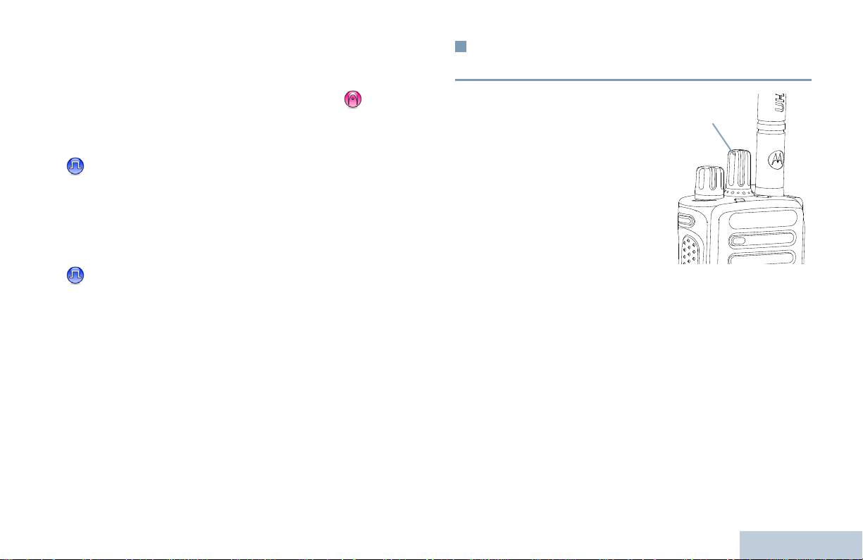
• Wird gerade kein Ruf getätigt, wird die Sendetaste (PTT) zur
Umschalten zwischen analogem und
Durchführung eines neuen Rufs verwendet (siehe Durchführen
digitalem Betriebsfunk
eines Funkrufs auf Seite 18).
Bedienelemente und Anzeigen
Jeder Kanal Ihres Funkgeräts
Ist die Freitonfunktion oder der Mithörton (Sidetone) aktiviert
kann als analoger
(je nach Programmierung) warten Sie auf das Ende des kurzen
Betriebsfunkkanal oder als
Hinweistons, bevor Sie sprechen.
digitaler Betriebsfunkkanal
konfiguriert werden. Schalten
Während eines Rufs und wenn die Funktion ‘Kanal frei-
Sie mit dem
Anzeige’ an Ihrem Funkgerät aktiviert ist (wird von Ihrem
Kanalwahlschalter zwischen
Händler programmiert), hören Sie einen kurzen Hinweiston,
analogem und digitalem
sobald die Sendetaste (PTT) am Zielfunkgerät (das Ihren Ruf
Kanal um.
empfangende Funkgerät) freigegeben wird, der Ihnen mitteilt,
Wenn Sie von digital auf
dass Sie nun auf diesem Kanal antworten können.
analog umschalten, sind
bestimmte Funktionen nicht
Sie hören auch einen ununterbrochenen Sendesperrenton,
verfügbar.
wenn Ihr Ruf unterbrochen wird, z.B. wenn das Funkgerät
einen Notruf empfängt. Der Sperrton weist Sie darauf hin,
Ihr Funkgerät verfügt auch über Funktionen, die sowohl analog als
auch digital verfügbar sind. Es gibt dabei geringe Unterschiede in
dass Sie Ihre Sendetaste freigeben müssen.
der Funktionsweise, die die Leistung des Funkgeräts jedoch NICHT
beeinflussen.
HINWEIS: Im Modus Dual-Scan schaltet das Funkgerät ebenfalls
zwischen digitalem und analogem Modus um (siehe
Scan auf Seite 24).
9
Deutsch
Kanalwahlschalter

Manuelles Hinzufügen oder Löschen von Einträgen der Roaming-
IP-Site-Verbindung
Liste ist nicht möglich. Weitere Informationen erhalten Sie von
Ihrem Systemadministrator oder Händler.
Mithilfe dieser Funktion kann das Funkgerät über ein IP-Netz
(Internetprotokoll) Verbindung mit verschiedenen verfügbaren Sites
aufnehmen und somit seinen Betriebsfunk-Kommunikationsbereich
Capacity Plus
über die Reichweite einer einzelnen Site hinaus ausdehnen.
Verlässt das Funkgerät den Bereich einer Site und tritt in den
Capacity Plus ist eine Single-Site-Bündelfunkkonfiguration des
Bereich einer anderen ein, nimmt es mit dem Repeater der neuen
MOTOTRBO-Funksystems, die mithilfe mehrerer verfügbarer
Site Verbindung auf, um Rufe/Datenübertragungen zu senden bzw.
Kanäle hunderte von Benutzern und bis zu 254 Gruppen
zu empfangen. Je nach Funkgeräteeinstellungen erfolgt dies
unterstützt. Dadurch kann Ihr Funkgerät im Repeater-Modus die
automatisch oder manuell.
verfügbare Zahl vorprogrammierter Kanäle effizient nutzen.
Lautet die Einstellung auf automatisch, durchsucht das Funkgerät
Symbole für in Capacity Plus nicht verfügbare Funktionen stehen
alle verfügbaren Sites, wenn das Signal der aktuell verwendeten
im Menü nicht zur Verfügung. Wird durch Drücken einer
Site schwach ist oder das Funkgerät kein Signal der aktuellen Site
programmierbaren Taste eine Funktion aufgerufen, das für
ausfindig machen kann. Das Funkgerät wechselt dann auf den
Capacity Plus nicht verfügbar ist, ertönt ein negativer Anzeigeton.
Repeater mit dem höchsten RSSI-Wert (Empfangssignalstärke).
Ihr Funkgerät hat auch Funktionen, die im digitalen Betriebsfunk, im
Bei einer manuellen Site-Suche sucht das Funkgerät nach der
IP-Site-Verbindungsmodus in Capacity Plus und in Linked Capacity
nächsten, derzeit in Reichweite befindlichen Site der Roam-Liste
Plus verfügbar sind. Die kleineren Funktionsunterschiede der
(die aber vielleicht nicht das stärkste Signal bietet) und wechselt auf
jeweiligen Merkmale haben KEINEN Einfluss auf die Leistung Ihres
diese über.
Funkgeräts.
HINWEIS: Auf jedem Kanal kann Scan oder Roam aktiviert
Weitere Informationen über diese Konfiguration erhalten Sie von
werden, nicht jedoch beide Funktionen gleichzeitig.
Ihrem Systemverwalter oder Händler.
Kanäle, für die diese Funktion aktiviert ist, können einer
bestimmten Roam-Liste hinzugefügt werden. Während des
automatischen Roaming-Suchlaufs durchsucht das Funkgerät den
Bedienelemente und Anzeigen
Kanal/die Kanäle der Roaming-Liste, um die beste Site zu finden.
Eine Roaming-Liste unterstützt bis zu 16 Kanäle (einschließlich des
gewählten Kanals).
10
Deutsch

Jeder Kanal, auf dem Linked Capacity Plus aktiviert ist, kann in eine
Linked Capacity Plus
Roaming-Liste aufgenommen werden. Während des
automatischen Roaming-Suchlaufs durchsucht das Funkgerät
Bedienelemente und Anzeigen
Linked Capacity Plus ist eine Multi-Site-Mehrkanal-
diese Kanäle, um die beste Site zu finden.
Bündelfunkkonfiguration des MOTORTRBO-Funksystems, die die
besten Eigenschaften von Capacity Plus und IP-Site-Verbindung in
HINWEIS: Manuelles Hinzufügen oder Löschen von Einträgen der
sich vereint.
Roaming-Liste ist nicht möglich. Weitere Informationen
erhalten Sie von Ihrem Systemadministrator oder
Mithilfe von Linked Capacity Plus kann das Funkgerät über ein
Händler.
IP-Netz (Internetprotokoll) Verbindung mit verschiedenen
verfügbaren Sites aufnehmen und somit seinen Bündelfunk-
Wie auch bei Capacity Plus stehen Symbole für in Linked Capacity
Kommunikationsbereich über die Reichweite einer einzelnen Site
Plus nicht verfügbare Funktionen im Menü nicht zur Verfügung.
hinaus ausdehnen. Indem es die insgesamt verfügbare Zahl
Wird durch Drücken einer programmierbaren Taste eine Funktion
programmierter Kanäle, die von jeder der verfügbaren Sites
aufgerufen, die für Linked Capacity Plus nicht verfügbar ist, ertönt
unterstützt werden, effizient nutzt, steigert Linked Capacity Plus
ein negativer Anzeigeton.
auch die Kapazität.
Weitere Informationen über diese Konfiguration erhalten Sie von
Verlässt das Funkgerät den Bereich einer Site und tritt in den
Ihrem Systemverwalter oder Händler.
Bereich einer anderen ein, nimmt es mit dem Repeater der neuen
Site Verbindung auf, um Rufe/Datenübertragungen zu senden bzw.
zu empfangen. Je nach Funkgeräteeinstellungen erfolgt dies
automatisch oder manuell.
Lautet die Einstellung auf automatisch, durchsucht das Funkgerät
alle verfügbaren Sites, wenn das Signal der aktuell verwendeten
Site schwach ist oder das Funkgerät kein Signal der aktuellen Site
ausfindig machen kann. Das Funkgerät wechselt dann auf den
Repeater mit dem höchsten RSSI-Wert (Empfangssignalstärke).
Bei einer manuellen Site-Suche sucht das Funkgerät nach der
nächsten, derzeit in Reichweite befindlichen Site der Roam-Liste
(die aber vielleicht nicht das stärkste Signal bietet) und wechselt auf
diese über.
11
Deutsch
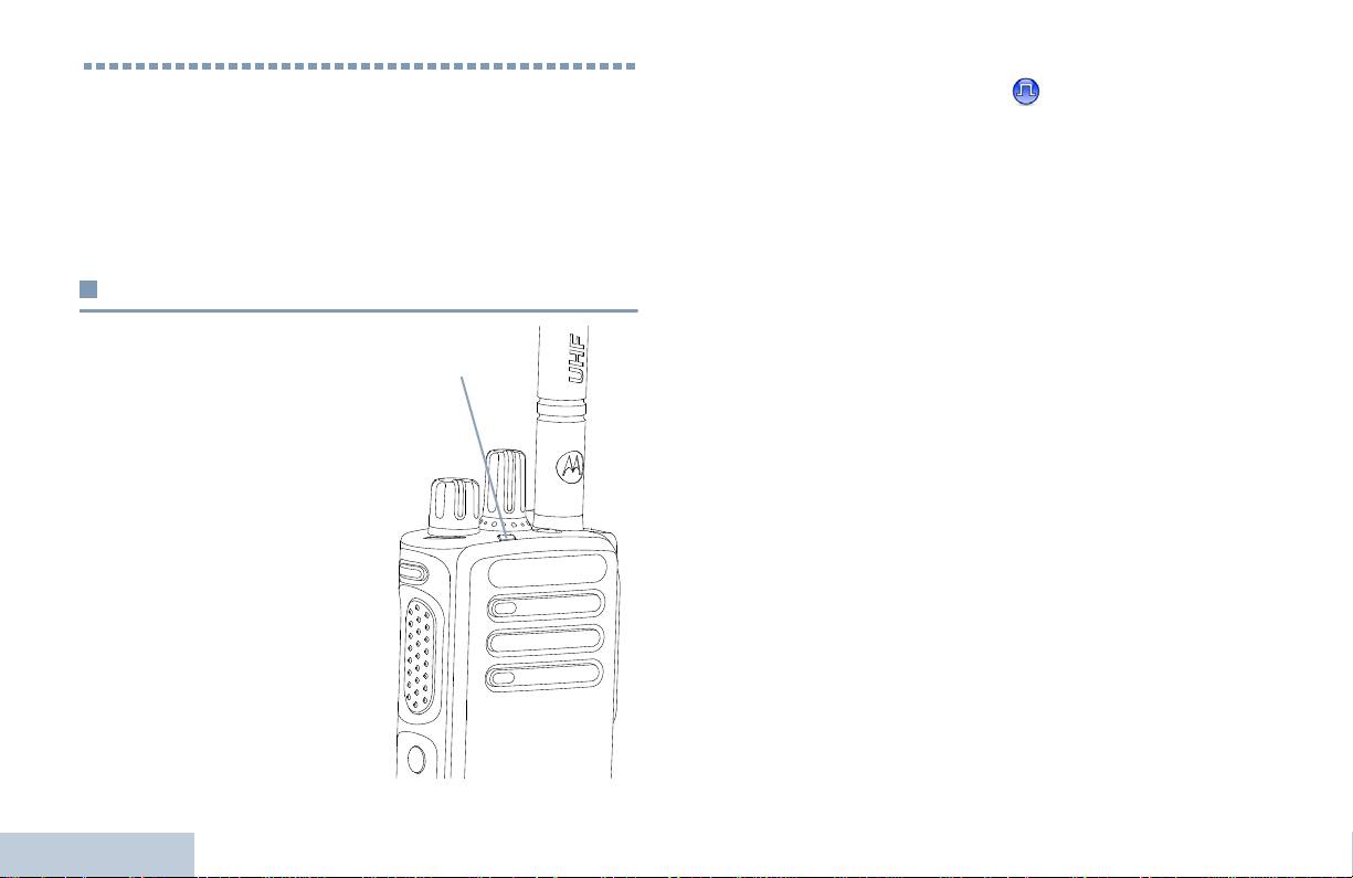
Doppelt grün blinkend – Funkgerät empfängt einen Ruf oder
Identifizieren von Statusanzeigen
Daten mit aktivierter Verschlüsselung .
Gelb – Funkgerät überwacht einen Betriebsfunkkanal. Zeigt auch
Das Funkgerät zeigt seinen jeweiligen Betriebsstatus durch
eine mittelmäßige Batterieladung an, wenn die Taste für
Folgendes an:
Akkuleistung gedrückt wird.
LED-Anzeige . . . . . . . . . . . . . . . . . . . . . . . . . . . . . . . . . . Seite 12
Gelb blinkend – Funkgerät sucht nach Aktivität (d.h. führt Scan
Anzeigetöne . . . . . . . . . . . . . . . . . . . . . . . . . . . . . . . . . . . Seite 13
durch) oder empfängt einen Hinweiston bzw. alle lokalen Linked
Töne. . . . . . . . . . . . . . . . . . . . . . . . . . . . . . . . . . . . . . . . . Seite 13
Capacity Plus Kanäle sind z.Zt. belegt.
Doppelt gelb blinkend – Funkgerät ist im Capacity Plus oder
LED-Anzeige
Linked Capacity Plus Modus nicht mehr mit dem Repeater in
Verbindung, alle Capacity Plus Kanäle und Linked Capacity Plus
Die LED-Anzeige zeigt den
Kanäle sind z.Zt. belegt, automatisches Roaming ist aktiviert,
Betriebsstatus Ihres Funkgeräts
Funkgerät sucht aktiv nach neuer Anlage/Site. Außerdem zeigt es
an.
an, dass das Funkgerät noch auf einen Gruppenruf-Anrufton
antworten muss oder gesperrt ist.
Rot blinkend – das Funkgerät
sendet mit geringer Akkuleistung,
HINWEIS:
Im Betriebsfunk zeigt die grün blinkende LED an, dass
empfängt einen Notruf oder der
das Funkgerät Funkaktivität erfasst. Je nach Art des
Selbsttest beim Einschalten hat
digitalen Protokolls hat die erfasste Funkaktivität
versagt.
eventuell Einfluss auf den programmierten Kanal des
Grün – Funkgerät schaltet sich
Funkgeräts.
gerade ein oder sendet. Zeigt
auch eine mittelmäßige
In Capacity Plus und Linked Capacity Plus zeigt die
Batterieladung an, wenn die
LED nicht an, wenn das Funkgerät Funkaktivität
Taste für Akkuleistung gedrückt
erfasst.
wird.
Grün blinkend – Funkgerät
Identifizieren von Statusanzeigen
empfängt einen Ruf oder Daten
ohne aktivierte Verschlüsselung
oder erfasst Funkaktivität.
12
Deutsch
LED-Anzeige
Anzeigetöne
Töne
Identifizieren von Statusanzeigen
Hinweistöne sind hörbare Anzeigen zum Funkgerätestatus oder der
Hoher Ton Tiefer Ton
Reaktion des Funkgeräts auf empfangene Daten.
Ununterbrochener
Positiver Anzeigeton
Ein gleichförmiger Ton. Erklingt
Ton
ununterbrochen bis zur Beendung.
Negativer Anzeigeton
Periodischer Ton Erklingt periodisch je nach eingestellter
Tonlänge. Der Ton beginnt, stoppt und
wiederholt sich.
Wiederholter Ton
Ein einzelner Ton, der sich wiederholt, bis
der Benutzer ihn abschaltet.
Kurzer Einzelton Erklingt nur einmal kurz (Tonlänge ist
vorgegeben).
13
Deutsch
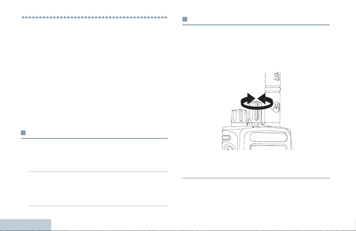
Auswählen eines Kanals
Durchführung und Empfang von
Das Senden und Empfangen von Übertragungen erfolgt jeweils
Rufen
über einen Kanal. Je nach der Konfiguration Ihres Funkgeräts
Wenn Sie sich mit der Konfiguration des MOTOTRBO
können die Kanäle jeweils verschieden programmiert sein, um
Handfunkgeräts vertraut gemacht haben, können Sie Ihr Funkgerät
verschiedene Benutzergruppen zu unterstützen, oder sie können
benutzen.
verschiedene Funktionsmerkmale aufweisen. Nach der Auswahl
Lesen Sie die folgenden Abschnitte, um sich mit den
der erforderlichen Zone wählen Sie den Kanal, auf dem Sie senden
grundlegenden Ruffunktionen vertraut zu machen:
oder empfangen wollen.
Auswählen einer Zone . . . . . . . . . . . . . . . . . . . . . . . . . . . Seite 14
Auswählen eines Kanals . . . . . . . . . . . . . . . . . . . . . . . . . Seite 14
Empfangen und Beantworten eines Rufs. . . . . . . . . . . . . Seite 15
Durchführen eines Funkrufs. . . . . . . . . . . . . . . . . . . . . . . Seite 18
Beenden eines Funkrufs . . . . . . . . . . . . . . . . . . . . . . . . . Seite 21
Repeater umgehen . . . . . . . . . . . . . . . . . . . . . . . . . . . . . Seite 21
Überwachungsfunktionen (Monitoring) . . . . . . . . . . . . . . Seite 22
Auswählen einer Zone
Eine Zone ist eine Gruppe von Kanälen. Ihr Funkgerät unterstützt
bis zu 32 Kanäle und 2 Zonen mit maximal 16 Kanälen pro Zone.
Vorgehensweise:
Vorgehensweise:
Drehen Sie den Kanalwahlschalter, um den Kanal mit dem
1 Drücken Sie die vorprogrammierte Zone-Taste.
aktiven Gruppenaliasnamen bzw. der aktiven Gruppen-ID zu
wählen.
2 Sie hören einen positiven Ton, der anzeigt, dass das Funkgerät
von Zone 1 auf Zone 2 umgeschaltet wurde.
Durchführung und Empfang von Rufen
ODER
Sie hören einen negativen Ton, der anzeigt, dass das
Funkgerät von Zone 2 auf Zone 1 umgeschaltet wurde.
14
Deutsch
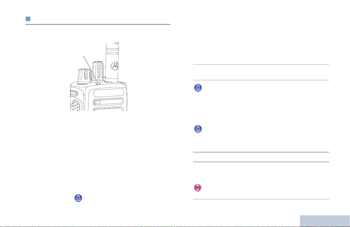
Empfangen und Beantworten eines Rufs
Empfangen und Beantworten eines Gruppenrufs
Ein Ruf von einer Gruppe kann nur empfangen werden, wenn Ihr
Sobald der Kanal, die Teilnehmer-ID oder Gruppen-ID angezeigt
Durchführung und Empfang von Rufen
Funkgerät als Mitglied dieser Gruppe konfiguriert ist.
wird, können Sie Rufe empfangen und beantworten.
Vorgehensweise:
1 Die LED blinkt grün. Die Stummschaltung Ihres Funkgeräts wird
aufgehoben und der ankommende Ruf ist über den
Lautsprecher des Funkgeräts zu hören.
2 Halten Sie das Funkgerät zum Antworten senkrecht 2,5 bis
5,0 cm vom Mund entfernt.
3 Ist die Funktion ‘Kanal frei-Anzeige’ aktiviert, hören Sie
einen kurzen Hinweiston, sobald die Sendetaste (PTT) am
sendenden Funkgerät freigegeben wird, der Ihnen mitteilt, dass
Sie nun auf diesem Kanal antworten können.
Drücken Sie zum Beantworten des Rufs die Sendetaste (PTT).
Die LED leuchtet ununterbrochen grün, wenn das Funkgerät sendet
ODER
und blinkt grün, wenn das Funkgerät empfängt.
Wenn die Sprachunterbrechungsfunktion aktiviert ist,
HINWEIS: Während einer Übertragung leuchtet die Funkgerät-
LED grün. Während des Empfangs eines Rufs mit
drücken Sie die Sendetaste (PTT), um den aktuellen Ruf des
aktivierter Verschlüsselung doppelt-blinkt sie grün.
sendenden Funkgeräts abzubrechen und den Kanal
freizumachen, damit Sie sprechen/antworten können.
Zum Entschlüsseln eines verschlüsselten Rufs muss
4 Die LED leuchtet ununterbrochen grün.
Ihr Funkgerät denselben Privacy-Key ODER
denselben Key-Wert und dieselbe Key-ID aufweisen
5 Warten Sie, bis der Freiton verstummt (wenn aktiviert), und
(von Ihrem Händler programmiert) wie das sendende
sprechen Sie deutlich in das Mikrofon.
Funkgerät (von dem Sie den Ruf empfangen).
ODER
Weitere Informationen hierzu siehe Verschlüsselt auf
Warten Sie, bis der Mithörton (Sidetone) verstummt (falls
Seite 31.
aktiviert), und sprechen Sie dann deutlich in das Mikrofon.
15
Deutsch
LED-
Anzeige

6 Geben Sie die Sendetaste (PTT) zum Hören frei.
4 Drücken Sie zum Beantworten des Rufs die Sendetaste (PTT).
Die LED leuchtet ununterbrochen grün.
7 Wird während einer vorprogrammierten Zeitdauer nicht
gesprochen, endet der Ruf automatisch.
5 Warten Sie, bis der Freiton verstummt (wenn aktiviert), und
sprechen Sie deutlich in das Mikrofon.
Eine genaue Beschreibung zur Durchführung eines Gruppenrufs
6 Geben Sie die Sendetaste (PTT) zum Hören frei.
finden Sie unter Durchführen eines Gruppenrufs auf Seite 18.
7 Wird während einer vorprogrammierten Zeitdauer nicht
gesprochen, endet der Ruf automatisch.
Empfangen und Beantworten eines Einzelrufs
8 Sie hören einen kurzen Ton.
Ein Einzelruf ist ein Ruf von einem einzelnen Funkgerät an ein
anderes einzelnes Funkgerät.
Eine genaue Beschreibung zur Durchführung eines Einzelrufs
Vorgehensweise:
finden Sie unter Durchführen eines Einzelrufs auf Seite 19.
Wenn Sie einen Einzelruf empfangen, geschieht Folgendes:
1 Die LED blinkt grün. Die Stummschaltung Ihres Funkgeräts wird
aufgehoben und der ankommende Ruf ist über den
Lautsprecher des Funkgeräts zu hören.
2 Halten Sie das Funkgerät zum Antworten senkrecht 2,5 bis
5,0 cm vom Mund entfernt.
3 Ist die Funktion ‘Kanal frei-Anzeige’ aktiviert, hören Sie einen
kurzen Hinweiston, sobald die Sendetaste (PTT) am
sendenden Funkgerät freigegeben wird, der Ihnen mitteilt, dass
Sie nun auf diesem Kanal antworten können.
ODER
Wenn die Sprachunterbrechungsfunktion aktiviert ist, drücken
Sie die Sendetaste (PTT), um den aktuellen Ruf des
sendenden Funkgeräts abzubrechen und den Kanal
Durchführung und Empfang von Rufen
freizumachen, damit Sie sprechen/antworten können.
16
Deutsch

Empfangen eines Rundumrufs
Empfangen und Beantworten eines Selektivrufs
Ein Rundumruf ist ein Ruf von einem individuellen Funkgerät an
Ein Selektivruf ist ein Ruf von einem einzelnen Funkgerät an ein
Durchführung und Empfang von Rufen
alle anderen Funkgeräte auf dem Kanal. Diese Rufart wird für
anderes einzelnes Funkgerät. In einem Analogsystem ist er ein
Ankündigungen verwendet, denen alle Benutzer volle
Einzelruf.
Aufmerksamkeit schenken müssen.
Vorgehensweise:
Vorgehensweise:
Wenn Sie einen Selektivruf empfangen, geschieht Folgendes:
Wenn Sie einen Rundumruf empfangen, geschieht Folgendes:
1 Die LED blinkt grün.
1 Es ertönt ein Ton und die LED blinkt grün. Die Stummschaltung
2 Halten Sie das Funkgerät zum Antworten senkrecht 2,5 bis
Ihres Funkgeräts wird aufgehoben und der ankommende Ruf ist
5,0 cm vom Mund entfernt. Die Stummschaltung Ihres
über den Lautsprecher des Funkgeräts zu hören.
Funkgeräts wird aufgehoben und der ankommende Ruf ist über
2 Nach Ende des Rundumrufs kehrt das Funkgerät zum vor dem
den Lautsprecher des Funkgeräts zu hören.
Empfang des Rufs angezeigten Bildschirm zurück. Rundumrufe
3 Ist die Funktion „Kanal frei-Anzeige“ aktiviert, hören Sie einen
werden jeweils ohne eine vorbestimmte Wartezeit beendet.
kurzen Hinweiston, sobald die Sendetaste (PTT) am
Ist die Funktion ‘Kanal frei-Anzeige’ aktiviert, hören Sie
sendenden Funkgerät freigegeben wird, der Ihnen mitteilt, dass
einen kurzen Hinweiston, sobald die Sendetaste (PTT) am
Sie nun auf diesem Kanal antworten können.
sendenden Funkgerät freigegeben wird, der Ihnen mitteilt, dass
Sie nun auf diesem Kanal antworten können.
4 Drücken Sie zum Beantworten des Rufs die Sendetaste (PTT).
Die LED leuchtet grün.
Auf einen Rundumruf kann nicht geantwortet werden.
5 Warten Sie, bis der Freiton verstummt ist (wenn aktiviert) und
HINWEIS: Das Funkgerät unterbricht den Empfang eines
sprechen Sie deutlich in das Mikrofon.
Rundumrufs (Alle rufen), wenn Sie während des Rufs
6 Geben Sie die Sendetaste zum Hören frei.
auf einen anderen Kanal schalten. Während eines
Rundumrufs können Sie keine der programmierten
7 Wird während einer vorprogrammierten Zeitdauer nicht
Tastenfunktionen verwenden, bis der Ruf beendet wird.
gesprochen, endet der Ruf automatisch.
8 Sie hören einen kurzen Ton.
Eine genaue Beschreibung zur Durchführung eines Selektivrufs
finden Sie unter Durchführen eines Selektivrufs auf Seite 19.
17
Deutsch
Vorgehensweise:
Durchführen eines Funkrufs
1 Wählen Sie den Kanal mit dem/der aktiven Gruppenaliasnamen
Wenn Sie Ihren Kanal gewählt haben, können Sie eine(n)
oder -ID; siehe Auswählen eines Kanals auf Seite 14.
Teilnehmeraliasnamen oder -ID oder eine(n) Gruppenaliasnamen
ODER
oder -ID wie folgt auswählen:
Drücken Sie die programmierte Schnellwahltaste.
• mit dem Kanalwahlschalter
2 Halten Sie das Funkgerät zum Antworten senkrecht 2,5 bis
5,0 cm vom Mund entfernt.
• mit einer programmierten Schnellwahltaste
3 Drücken Sie zum Durchführen des Rufs die Sendetaste (PTT).
HINWEIS: Um mit aktivierter Verschlüsselung senden zu können,
Die LED leuchtet ununterbrochen grün.
muss die Verschlüsselungsfunktion auf diesem Kanal
aktiviert sein. Ausschließlich Funkgeräte mit
4 Warten Sie, bis der Freiton verstummt ist (wenn aktiviert) und
demselben Privacy-Key ODER demselben Key-Wert
sprechen Sie deutlich in das Mikrofon.
und derselben Key-ID wie Ihr Funkgerät können die
ODER
Übertragung entschlüsseln.
Warten Sie, bis der Mithörton (Sidetone) verstummt (falls
Weitere Informationen hierzu siehe
Verschlüsselt auf
aktiviert), und sprechen Sie dann deutlich in das Mikrofon.
Seite 31.
5 Geben Sie die Sendetaste (PTT) zum Hören frei. Sobald das
Die Schnellwahlfunktion ermöglicht die schnelle und
gerufene Funkgerät antwortet, blinkt die LED grün.
einfache Durchführung eines Gruppen- oder Einzelrufs
6 Ist die Funktion ‘Kanal frei-Anzeige’ aktiviert, hören Sie
an eine vorgegebene ID. Diese Funktion kann dem
kurzen oder langen Drücken einer programmierbaren
einen kurzen Hinweiston, sobald die Sendetaste (PTT) am
Taste zugewiesen werden. Einer Schnellwahltaste
Zielfunkgerät freigegeben wird, der Ihnen mitteilt, dass Sie nun
kann NUR EINE ID zugewiesen werden. Am
auf diesem Kanal antworten können. Drücken Sie zum
Funkgerät können mehrere Schnellwahltasten
Antworten die Sendetaste (PTT).
programmiert sein.
ODER
Wird eine vorbestimmte Zeit lang keine Sprachaktivität erfasst,
Durchführen eines Rufs mit dem Kanalwahlschalter
wird der Ruf beendet.
Durchführung und Empfang von Rufen
Durchführen eines Gruppenrufs
Ein Ruf an eine Gruppe kann nur ausgeführt werden, wenn Ihr
Funkgerät als Mitglied dieser Gruppe konfiguriert ist.
18
Deutsch

4 Warten Sie, bis der Freiton verstummt ist (wenn aktiviert) und
Durchführen eines Einzelrufs
sprechen Sie deutlich in das Mikrofon.
Sie können zwar einen Einzelruf empfangen und/oder beantworten,
Durchführung und Empfang von Rufen
5 Geben Sie die Sendetaste (PTT) zum Hören frei. Sobald das
der von einem befugten einzelnen Funkgerät eingeleitet wurde,
gerufene Funkgerät antwortet, blinkt die LED grün.
aber um einen Einzelruf einzuleiten, muss Ihr Funkgerät
6 Ist die Funktion ‘Kanal frei-Anzeige’ aktiviert, hören Sie einen
entsprechend programmiert worden sein.
kurzen Hinweiston, sobald die Sendetaste (PTT) am
Es gibt zwei Arten von Einzelrufen. Bei der ersten Art wird zunächst
Zielfunkgerät freigegeben wird, der Ihnen mitteilt, dass Sie nun
geprüft, ob das Zielfunkgerät verfügbar ist, bevor der Ruf eingeleitet
auf diesem Kanal antworten können. Drücken Sie zum
wird; bei der zweiten Art wird der Ruf unverzüglich aufgebaut.
Antworten die Sendetaste (PTT).
Ihr Händler hat nur eine dieser Einzelrufversionen in Ihr Funkgerät
ODER
einprogrammiert.
Wird während einer vorprogrammierten Zeitdauer nicht
gesprochen, endet der Ruf automatisch.
Wenn Sie versuchen, einen Einzelruf über die Schnellwahltaste
oder den Kanalschalter durchzuführen, und dieses Merkmal nicht
7 Sie hören einen kurzen Ton.
aktiviert ist, ertönt ein negativer Anzeigeton.
Verwenden Sie die Quick Text-Nachricht- oder
Durchführen eines Selektivrufs
Hinweistonfunktionen, um mit einem einzelnen Funkgerät Kontakt
Wie bei Einzelrufen können Sie zwar einen Selektivruf empfangen
aufzunehmen. Weitere Informationen finden Sie unter
und/oder beantworten, der von einem befugten einzelnen
Textnachrichtenfunktionen auf Seite 30 bzw. Hinweiston auf
Funkgerät eingeleitet wurde, aber um einen Selektivruf einzuleiten,
Seite 26.
muss Ihr Funkgerät entsprechend programmiert worden sein.
Vorgehensweise:
Procedure:
1 Wählen Sie den Kanal mit dem/der aktiven Gruppenaliasnamen
1 Wählen Sie den Kanal mit dem/der aktiven Gruppenaliasnamen
oder -ID; siehe Auswählen eines Kanals auf Seite 14.
oder -ID; siehe Auswählen eines Kanals auf Seite 14.
ODER
Drücken Sie die programmierte Schnellwahltaste.
2 Halten Sie das Funkgerät zum Antworten senkrecht 2,5 bis 5,0
cm vom Mund entfernt.
2 Halten Sie das Funkgerät zum Antworten senkrecht 2,5 bis
5,0 cm vom Mund entfernt.
3 Drücken Sie zum Durchführen des Rufs die Sendetaste (PTT).
Die LED leuchtet ununterbrochen grün.
3 Drücken Sie zum Durchführen des Rufs die Sendetaste (PTT).
Die LED leuchtet ununterbrochen grün.
19
Deutsch

4 Warten Sie, bis der Freiton verstummt ist (wenn aktiviert) und
4 Warten Sie, bis der Freiton verstummt ist (wenn aktiviert) und
sprechen Sie deutlich in das Mikrofon.
sprechen Sie deutlich in das Mikrofon.
ODER
5 Geben Sie die Sendetaste (PTT) zum Hören frei. Sobald das
gerufene Funkgerät antwortet, blinkt die LED grün.
Warten Sie, bis der Mithörton (Sidetone) verstummt (falls
aktiviert), und sprechen Sie dann deutlich in das Mikrofon.
6 Ist die Funktion ‘Kanal frei-Anzeige’ aktiviert, hören Sie einen
kurzen Hinweiston, sobald die Sendetaste (PTT) am
Benutzer auf dem Kanal können auf einen Rundumruf nicht
Zielfunkgerät freigegeben wird, der Ihnen mitteilt, dass Sie nun
antworten.
auf diesem Kanal antworten können. Drücken Sie zum
Antworten die Sendetaste (PTT).
ODER
Wird während einer vorprogrammierten Zeitdauer nicht
gesprochen, endet der Ruf automatisch.
7 Sie hören einen kurzen Ton.
Durchführen eines Rundumrufs
Diese Funktion kann zum Senden eines Rufs an alle Benutzer des
Kanals eingesetzt werden. Ihr Funkgerät muss entsprechend
programmiert sein, um diese Rufart nutzen zu können.
Vorgehensweise:
1 Wählen Sie den Kanal mit dem/der aktiven Gruppenaliasnamen
oder -ID; siehe Auswählen eines Kanals auf Seite 14.
2 Halten Sie das Funkgerät zum Antworten senkrecht 2,5 bis
5,0 cm vom Mund entfernt.
Durchführung und Empfang von Rufen
3 Drücken Sie zum Durchführen des Rufs die Sendetaste (PTT).
Die LED leuchtet ununterbrochen grün.
20
Deutsch

Repeater umgehen
Beenden eines Funkrufs
Durchführung und Empfang von Rufen
Sie können auch dann Rufe tätigen und empfangen, wenn der
Mit dieser Funktion können Sie einen laufenden Gruppen- oder
Repeater nicht in Betrieb ist oder Ihr Funkgerät sich außerhalb der
Einzelruf abbrechen, um den Kanal zum Senden freizumachen,
Funkreichweite des Repeaters befindet, solange Sie in
z.B. wenn ein Funkgerät die Funkfrequenz „blockiert“, weil die
Funkreichweite anderer Funkgeräte sind.
Sendetaste versehentlich gedrückt wird.
Dies wird ’Repeater umgehen’ genannt.
Damit Sie diese Funktion benutzen können, muss Ihr Funkgerät
entsprechend programmiert sein.
HINWEIS: Diese Funktion ist in Capacity Plus und Linked
Capacity Plus nicht verfügbar.
Vorgehensweise:
Vorgehensweise:
Auf dem gewünschten Kanal:
1 Drücken Sie die vorprogrammierte Rufunterbrechungstaste.
1 Drücken Sie die vorprogrammierte Repeater/Repeater-
umgehen-Taste.
2 Warten Sie auf die Quittung.
2 Das Funkgerät zeigt durch einen positiven Anzeigeton an, dass
3 Das Funkgerät zeigt durch einen positiven Ton an, dass der
das Funkgerät auf Repeater-umgehen-Betrieb geschaltet
Kanal jetzt frei ist.
wurde.
ODER
ODER
Das Funkgerät zeigt durch einen negativen Ton an, dass das
Das Funkgerät zeigt durch einen negativen Anzeigeton an,
Funkgerät den Kanal nicht freigeben kann.
dass das Funkgerät auf Repeaterbetrieb geschaltet wurde.
Wenn Sie einen unterbrechbaren Ruf senden, der über diese
Die Repeater-umgehen-Einstellung bleibt auch nach Ausschalten
Funktion abgebrochen wird, gibt Ihr Funkgerät einen negativen
des Funkgeräts erhalten.
Hinweiston ab, bis Sie die Sendetaste freigeben. Bei einem
unterbrochenen Funkgerät mit Display wird im Display Ruf
unterbrochen angezeigt.
21
Deutsch

Überwachungsfunktionen (Monitoring)
Dauer-Monitor
Mit dieser Funktion kann ein ausgewählter Kanal fortlaufend auf
Aktivität überwacht werden.
Überwachen eines Kanals
HINWEIS: Diese Funktion ist in Capacity Plus und Linked
Setzen Sie die Monitorfunktion ein, um sicherzustellen, dass ein
Capacity Plus nicht verfügbar.
Kanal frei ist, bevor Sie senden.
Vorgehensweise:
HINWEIS: Diese Funktion ist in Capacity Plus und Linked
Capacity Plus nicht verfügbar.
1 Drücken Sie die vorprogrammierte Dauer-Monitor-Taste.
Vorgehensweise:
2 Das Funkgerät gibt einen Hinweiston ab und die LED leuchtet
gelb.
1 Drücken und halten Sie die vorprogrammierte Monitortaste, um
zu hören, ob ein Kanal frei ist.
3 Drücken Sie die vorprogrammierte Dauer-Monitor-Taste, um
den Dauer-Monitor-Modus wieder zu verlassen.
2 Je nachdem, wie Ihr Funkgerät programmiert ist, hören Sie
Funkverkehr oder es herrscht Funkstille.
4 Das Funkgerät gibt einen Hinweiston ab und die LED erlischt.
3 Wenn Sie „Weißrauschen” hören (d.h. dass der Kanal frei ist),
drücken Sie die Sendetaste (PTT), um zu sprechen, und geben
Sie sie zum Zuhören frei. Die LED leuchtet gelb.
Durchführung und Empfang von Rufen
22
Deutsch

Scan-Listen
Erweiterte Funktionen
Erweiterte Funktionen
Scan-Listen werden erstellt und individuellen Kanälen/Gruppen
Mit dieser Navigationshilfe können Sie mehr über die komplexeren
zugewiesen. Das Funkgerät sucht nach Sprachaktivität, indem es
Funktionen erfahren, die Ihr Funkgerät bietet.
die in der Scan-Liste für den aktuellen Kanal/die aktuelle Gruppe
Scan-Listen . . . . . . . . . . . . . . . . . . . . . . . . . . . . . . . . . . . Seite 23
festgelegte Kanal-/Gruppenfolge zyklisch durchläuft.
Scan . . . . . . . . . . . . . . . . . . . . . . . . . . . . . . . . . . . . . . . . . Seite 24
Ihr Funkgerät unterstützt bis zu 250 Scan-Listen mit jeweils
Rufanzeigeeinstellungen . . . . . . . . . . . . . . . . . . . . . . . . . Seite 26
höchstens 16 Mitgliedern pro Liste. In jede Scan-Liste können
Hinweiston . . . . . . . . . . . . . . . . . . . . . . . . . . . . . . . . . . . . Seite 26
sowohl analoge als auch digitale Einträge aufgenommen werden.
Notrufbetrieb. . . . . . . . . . . . . . . . . . . . . . . . . . . . . . . . . . . Seite 27
Textnachrichtenfunktionen . . . . . . . . . . . . . . . . . . . . . . . . Seite 30
HINWEIS: Diese Funktion ist in Capacity Plus und Linked
Verschlüsselt . . . . . . . . . . . . . . . . . . . . . . . . . . . . . . . . . . Seite 31
Capacity Plus nicht verfügbar.
Multi-Site-Bedienelemente. . . . . . . . . . . . . . . . . . . . . . . . Seite 32
Alleinarbeiterschutz . . . . . . . . . . . . . . . . . . . . . . . . . . . . . Seite 33
Passwort-geschützter Zugriff auf das Funkgerät . . . . . . . Seite 33
Bluetooth . . . . . . . . . . . . . . . . . . . . . . . . . . . . . . . . . . . . . Seite 34
Nützliche Funktionen/Dienstprogramme . . . . . . . . . . . . . Seite 36
23
Deutsch

Scan
Starten und Stoppen von Scan
Vorgehensweise:
Wenn Sie einen Scan starten, durchsucht das Funkgerät die
vorprogrammierte Scan-Liste des aktuellen Kanals auf
1 Drücken Sie die vorprogrammierte Scan-Taste.
Sprachaktivität.
ODER
Wählen Sie über den Kanalwahlschalter einen Kanal aus, für
Die LED blinkt gelb.
den der automatische Suchlauf aktiviert ist.
Während eines Dual-Scans schaltet das Funkgerät, wenn Sie sich
2 Beim Einschalten der Scan-Funktion blinkt die gelbe LED und
z.B. auf einem digitalen Kanal befinden, automatisch auf einen
analogen Kanal, wenn es dort Sprachaktivität erfasst, und bleibt für
das Funkgerät gibt einen positiven Anzeigeton ab.
die Dauer des Rufs auf dem Kanal. Umgekehrt gilt dasselbe.
ODER
Beim Ausschalten der Scan-Funktion erlischt die LED und das
Es gibt zwei Scan-Arten:
Funkgerät gibt einen negativen Anzeigeton ab.
• Hauptkanal-Scan (Manuell): Das Funkgerät durchsucht alle
Kanäle/Gruppen Ihrer Scan-Liste. Bei Aufnahme des Scans
startet das Funkgerät – je nach Einstellungen – automatisch auf
Beantworten eines Rufs während Suchlauf
dem/der zuletzt abgefragten „aktiven“ Kanal/Gruppe oder auf
Das Funkgerät stoppt während eines Suchlaufs auf einem Kanal/
dem Kanal, von dem aus der Scan eingeleitet wurde.
bei einer Gruppe, sobald es Aktivität erfasst. Es bleibt während
• Auto-Scan (Automatisch): Das Funkgerät beginnt den Scan
einer vorprogrammierten Zeitdauer, die „Haltezeit“ genannt wird,
automatisch, wenn Sie einen Kanal/eine Gruppe mit aktivierter
auf diesem Kanal.
Auto-Scan-Funktion auswählen.
Vorgehensweise:
HINWEIS: Diese Funktion ist in Capacity Plus und Linked
1 Halten Sie das Funkgerät senkrecht 2,5 bis 5,0 cm vom Mund
Capacity Plus nicht verfügbar.
entfernt.
Ist die Funktion ‘Kanal frei-Anzeige’ aktiviert, hören Sie
einen kurzen Hinweiston, sobald die Sendetaste (PTT) am
sendenden Funkgerät freigegeben wird, der Ihnen mitteilt, dass
Sie nun auf diesem Kanal antworten können.
Erweiterte Funktionen
2 Drücken Sie während der Haltezeit die Sendetaste (PTT). Die
LED leuchtet ununterbrochen grün.
24
Deutsch

3 Warten Sie, bis der Freiton verstummt (wenn aktiviert), und
Wiederaufnahme eines Störkanals
sprechen Sie deutlich in das Mikrofon.
Vorgehensweise:
ODER
Erweiterte Funktionen
Zur Wiederherstellung eines unterdrückten Störkanals gehen Sie
Warten Sie, bis der Mithörton (Sidetone) verstummt (falls
auf eine der folgenden Arten vor:
aktiviert), und sprechen Sie dann deutlich in das Mikrofon.
• Schalten Sie das Funkgerät aus und dann wieder ein ODER
4 Geben Sie die Sendetaste (PTT) zum Hören frei.
• Stoppen und starten Sie den Scan erneut über die
5 Wenn Sie nicht vor Ablauf der Haltezeit antworten, nimmt das
vorprogrammierte Scan-Taste, ODER
Funkgerät den Scan wieder auf und durchsucht weitere Kanäle/
• Wechseln Sie mit dem Kanalwahlschalter den Kanal.
Gruppen.
Unterdrücken eines Störkanals
Auswahlverfahren nach Signalgüte
(Vote-Scan)
Kommen auf einem Kanal andauernd Störgeräusche oder
unerwünschte Rufe vor (sog. „Störkanal“), können Sie diesen Kanal
vorübergehend wie folgt aus der Scan-Liste entfernen.
Das Auswahlverfahren nach Signalgüte bietet in Gegenden, in
denen mehrere Basisstationen identische Informationen auf
Diese Funktion kann auf den als „ausgewählten Kanal“ designierten
verschiedenen analogen Kanälen senden, eine flächendeckende
Kanal nicht angewandt werden.
Funkversorgung.
Vorgehensweise:
Ihr Funkgerät führt einen Suchlauf der analogen Kanäle mehrerer
Basisstationen durch und wählt dann das stärkste empfangene
1 Drücken Sie, während sich das Funkgerät auf einem
Signal aus. Sobald es das stärkste Signal ermittelt hat, hebt das
unerwünschten oder störenden Kanal befindet, die
Funkgerät die Stummschaltung für Übertragungen von dieser
vorprogrammierte Taste Störkanal Unterdrücken, bis ein Ton
Basisstation auf.
erklingt.
Während des Auswahlverfahrens blinkt die gelbe LED.
2 Geben Sie die Taste Störkanal Unterdrücken frei. Der
Störkanal wird gelöscht.
Zum Beantworten eines Rufs bei laufendem Signalgüte-
Auswahlverfahren gehen Beantworten eines Rufs während
Suchlauf auf Seite 24.
25
Deutsch

Rufanzeigeeinstellungen
Senden eines Hinweistons mit der
Schnellwahltaste
Die Ruftöne für einen empfangenen Einzelruf können ein- oder
Vorgehensweise:
ausgeschaltet werden (siehe Ein-/Ausschalten der Funkgerätruf-
1 Drücken Sie die vorprogrammierte Schnellwahltaste, um
/Hinweistöne auf Seite 37).
einen Hinweiston an die vorgegebene ID zu senden.
2 Während das Funkgerät den Hinweiston sendet, leuchtet die
Zunehmende Alarmtonlautstärke
LED ununterbrochen grün.
Das Funkgerät kann auf Dauerhinweis bei Nichtbeantworten eines
Rufs programmiert werden. Dieser Dauerhinweis erfolgt dadurch,
3 Wird die Rufhinweistonquittung empfangen, werden zwei
dass der Alarmton automatisch zunehmend lauter wird.
Zirptöne abgegeben.
ODER
Diese Funktion wird als Escalert bezeichnet.
Wird die Rufhinweistonquittung nicht empfangen, erklingt ein
tiefer Ton.
Hinweiston
Paging mit Hinweiston erlaubt Ihnen, einen bestimmten
Funkgerätbenutzer dazu aufzufordern, Sie bei nächster
Gelegenheit zurückzurufen. Diese Funktion kann über eine
programmierte Schnellwahltaste aufgerufen werden.
Empfangen und Beantworten eines Hinweistons
Vorgehensweise:
Wenn Sie einen Rufhinweiston empfangen:
1 Sie hören einen wiederholten Ton. Die LED blinkt gelb.
2 Drücken Sie die Sendetaste innerhalb von vier (4) Sekunden
Erweiterte Funktionen
nach Empfang eines Hinweistons, um den Einzelruf zu
beantworten.
26
Deutsch

Zudem kann jeder Alarm wie folgt charakterisiert werden:
Notrufbetrieb
• Regulär – Das Funkgerät sendet ein Alarmsignal, begleitet von
Erweiterte Funktionen
Ein Notrufalarm dient dazu, auf eine kritische Situation aufmerksam
Audio- und/oder visuellen Anzeigen.
zu machen. Ein Notruf kann jederzeit in jedem beliebigen Modus
• Still – Funkgerät sendet ein Alarmsignal ohne hörbare oder
gesendet werden, auch wenn auf dem aktuellen Kanal andere
sichtbare Anzeigen. Es empfängt Rufe ohne jegliche
Teilnehmer aktiv sind.
Tonausgabe über den Lautsprecher des Funkgeräts, bis Sie die
Ihr Händler kann festlegen, wie lange die vorprogrammierte
PTT drücken, um den Ruf einzuleiten.
Notruftaste gedrückt werden muss, allerdings ist die Dauer für das
• Still mit Sprache – Funkgerät sendet ein Alarmsignsal ohne
lange Drücken die gleiche wie bei allen anderen Tasten:
hörbare oder sichtbare Anzeigen, ankommende Rufe sind aber
• Kurz drücken – Zwischen 0,05 Sekunden und 0,75 Sekunden
über den Lautsprecher hörbar.
• Lang drücken – Zwischen 1,00 Sekunden und 3,75 Sekunden
Der vorprogrammierten Notruftaste kann jeweils nur einer der
oben angeführten Notrufalarme zugewiesen werden.
Die Notruftaste ist mit der Notruf-Ein/Aus-Funktion belegt. Für
Informationen über die zugewiesene Funktionsweise der
Senden eines Notrufalarms
Notruftaste wenden Sie sich bitte an Ihren Händler.
Mit dieser Funktion senden Sie einen Notrufalarm, ein Signal ohne
Wenn die Notruftaste zum Einschalten des Notruf-Modus durch
Sprache, das bei einer Gruppe von Funkgeräten eine Warnanzeige
kurzes Drücken programmiert ist, dann wird der Notruf-Modus
auslöst.
durch langes Drücken der Notruftaste beendet.
Vorgehensweise:
Wenn die Notruftaste zum Einschalten des Notruf-Modus durch
langes Drücken programmiert ist, dann wird der Notruf-Modus
1 Drücken Sie die programmierte Notrufeinschalttaste.
durch kurzes Drücken der Notruftaste beendet.
2 Die LED leuchtet ununterbrochen grün.
Ihr Funkgerät unterstützt drei Arten von Notrufalarmen:
3 Wird eine Notrufalarmquittung empfangen, wird der Notrufton
abgegeben. Die LED blinkt grün.
• Notrufalarm
ODER
• Notrufalarm mit Ruf
Empfängt Ihr Funkgerät keine Notrufalarmquittung und wurden
• Notrufalarm mit nachfolgendem Sprachruf
alle erneuten Versuche durchgeführt, wird ein tiefer Ton
abgegeben.
27
Deutsch
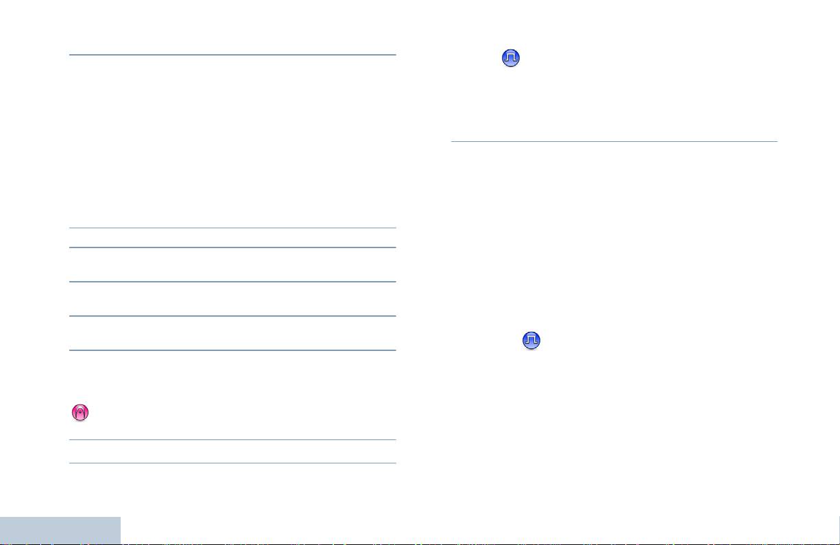
4 Das Funkgerät verlässt den Notrufalarmmodus.
8 Ein kurzer Hinweiston ertönt, sobald der Kanal für Ihre Antwort
frei wird ( wenn die Funktion zur Anzeige freier Kanäle
Ist Ihr Funkgerät auf Still eingestellt, gibt es im Notruf-Modus keine
aktiviert ist). Drücken Sie die Sendetaste (PTT), um zu
akustischen oder optischen Anzeigen ab.
antworten.
ODER
Senden eines Notrufalarms mit Ruf
Drücken Sie am Ende Ihres Rufs zum Beenden des
Notruf-Modus die Notrufausschalttaste.
Mithilfe dieser Funktion können Sie einen Notrufalarm an eine
Gruppe von Funkgeräten senden. Nach erfolgter Quittung durch ein
Ist Ihr Funkgerät auf Still eingestellt, gibt es im Notruf-Modus keine
Funkgerät in der Gruppe können die Funkgeräte der Gruppe auf
akustischen oder optischen Anzeigen ab und lässt die Tonausgabe
einem vorprogrammierten Notrufkanal miteinander kommunizieren.
empfangener Rufe über den Lautsprecher des Funkgeräts nicht zu,
Vorgehensweise:
bis Sie die Sendetaste (PTT) drücken, um den Ruf einzuleiten.
1 Drücken Sie die programmierte Notrufeinschalttaste.
Ist Ihr Funkgerät auf Still mit Sprache eingestellt, gibt es im
2 Die LED leuchtet ununterbrochen grün.
Notruf-Modus keine akustischen oder optischen Anzeigen ab, lässt
aber die Tonausgabe ankommender Rufe über den Lautsprecher
3 Wird eine Notrufalarmquittung empfangen, wird der Notrufton
des Funkgeräts zu. Diese Anzeigen erscheinen nur dann, wenn Sie
abgegeben. Die LED blinkt grün.
die Sendetaste (PTT) drücken, um den Ruf einzuleiten oder zu
4 Halten Sie das Funkgerät senkrecht 2,5 bis 5,0 cm vom Mund
beantworten.
entfernt.
5 Drücken Sie zum Durchführen des Rufs die Sendetaste (PTT).
Senden eines Notrufalarms mit nachfolgendem
Die LED leuchtet ununterbrochen grün.
Sprachruf
6 Warten Sie, bis der Freiton verstummt (wenn aktiviert), und
Mithilfe dieser Funktion können Sie einen Notrufalarm an eine
Gruppe von Funkgeräten senden. Ihr Funkgerät wird automatisch
sprechen Sie deutlich in das Mikrofon.
aktiviert, so dass Sie ohne Drücken der Sendetaste (PTT) mit der
ODER
Funkgerätegruppe kommunizieren können.
Warten Sie, bis der Mithörton (Sidetone) verstummt (falls
Dieser Modus mit aktiviertem Mikrofon wird auch „Notrufmikrofon”
aktiviert), und sprechen Sie dann deutlich in das Mikrofon.
Erweiterte Funktionen
genannt.
7 Geben Sie die Sendetaste (PTT) zum Zuhören frei.
28
Deutsch

Bei aktiviertem Notrufzyklusbetrieb werden für eine
4 Das Funkgerät stoppt den Sendevorgang automatisch:
einprogrammierte Dauer Notrufmikrofon und Empfangszeit
bei aktiviertem Notrufzyklusbetrieb nach Ablauf der Dauer des
abwechselnd wiederholt.
Zyklus zwischen Notrufmikrofon und Empfang von Rufen;
Erweiterte Funktionen
ODER
HINWEIS: Während des Notrufzyklusbetriebs werden
bei deaktiviertem Notrufzyklusbetrieb nach Ablauf der
empfangene Rufe über den Funkgerätlautsprecher
Notrufmikrofondauer.
ausgegeben.
5 Drücken Sie die Sendetaste (PTT), um erneut zu senden.
Wenn Sie während der vorprogrammierten Empfangszeit die
ODER
Sendetaste drücken, hören Sie einen Sperrton. Dieser Ton weist
Drücken Sie zum Verlassen des Notruf-Modus die
Sie darauf hin, dass Sie die Sendetaste freigeben müssen. Das
Notrufausschalttaste.
Funkgerät reagiert nicht auf das Drücken der Sendetaste und
bleibt im Notruf-Modus.
Ist Ihr Funkgerät auf Still eingestellt, gibt es im Notruf-Modus keine
akustischen oder optischen Anzeigen ab und lässt die Tonausgabe
HINWEIS: Wenn Sie die Sendetaste (PTT) bei aktiviertem
empfangener Rufe über den Lautsprecher des Funkgeräts nicht zu,
Notrufmikrofon drücken und sie bis nach Ablauf der
bis die programmierte Notrufmikrofon-Sendedauer abgelaufen ist
Notrufmikrofondauer gedrückt halten, sendet das
und Sie die Sendetaste (PTT) drücken.
Funkgerät weiterhin, bis Sie die Sendetaste (PTT)
freigeben.
Ist Ihr Funkgerät auf Still mit Sprache eingestellt, gibt es im
Notruf-Modus keine akustischen oder optischen Anzeigen ab,
Vorgehensweise:
wenn Sie den Ruf mit dem Notrufmikrofon durchführen, lässt
1 Drücken Sie die programmierte Notrufeinschalttaste.
aber die Tonausgabe über den Lautsprecher des Funkgeräts zu,
wenn das Zielfunkgerät nach Ablauf der programmierten
2 Die LED leuchtet ununterbrochen grün.
Notrufmikrofon-Sendedauer antwortet. Diese Anzeigen
3 Sobald Sie einen Ton hören, sprechen Sie deutlich in das
erscheinen nur dann, wenn Sie die Sendetaste (PTT) drücken.
Mikrofon. Ist die Notrufmikrofonfunktion aktiviert, sendet das
HINWEIS: Wird eine Notrufalarmanforderung nicht beantwortet,
Funkgerät auch ohne Drücken der Sendetaste (PTT) bis zum
versucht das Funkgerät nicht noch einmal, die
Ablauf der Notrufmikrofondauer automatisch.
Anforderung zu senden, sondern ruft den
Während des Sendens leuchtet die LED ununterbrochen grün.
Notrufmikrofonzustand direkt auf.
29
Deutsch

Neuinitalisierung eines Notruf-Modus
HINWEIS: Wird das Funkgerät ausgeschaltet, verlässt es den
Notruf-Modus. Wenn es wieder eingeschaltet wird,
HINWEIS: Dieses Merkmal trifft nur auf das Funkgerät zu, das den
leitet es den Notruf-Modus nicht automatisch wieder
Notrufalarm sendet.
ein.
Der Notruf-Modus kann auf eine von zwei Arten neu gestartet
werden:
• Sie wechseln den Kanal, während sich das Funkgerät im
Textnachrichtenfunktionen
Notruf-Modus befindet. Damit wird der Notruf-Modus verlassen.
Ist die Funktion Notrufalarm auf dem neuen Kanal aktiviert, leitet
das Funkgerät den Notruf-Modus erneut ein.
Senden einer Quick Text-Nachricht
• Wenn Sie während des Initierungs-/Sendezustands die
Sie können von Ihrem Händler vorprogrammierte Quick Text-
programmierte Notrufeinschalttaste drücken. Das Funkgerät
Nachrichten senden, indem Sie die entsprechend programmierte
verlässt daraufhin den Modus und leitet den Notruf-Modus erneut
Taste betätigen.
ein.
Vorgehensweise:
Verlassen des Notruf-Modus
1 Drücken Sie die vorprogrammierte Schnellwahltaste, um eine
HINWEIS: Dieses Merkmal trifft nur auf das Funkgerät zu, das den
vorprogrammierte Quick Text-Nachricht an eine vorgegebene
Notrufalarm sendet.
ID zu senden.
Das Funkgerät verlässt den Notruf-Modus, wenn eine der
2 Die LED leuchtet ununterbrochen grün.
folgenden Bedingungen gegeben ist:
3 Zwei Zirptöne zeigen an, dass die Nachricht erfolgreich
• Es wird eine Notrufalarmquittung empfangen (gilt nur für
gesendet wurde.
Notrufalarm) ODER
ODER
• Es wird ein Notrufausschalttelegramm empfangen ODER
Ein tiefer Ton zeigt an, dass die Nachricht nicht gesendet
werden kann.
• Alle Versuche, den Alarm zu senden, wurden bereits
unternommen
ODER
Erweiterte Funktionen
• Die Notrufausschalttaste wird gedrückt.
30
Deutsch

Wenn Sie einen verschlüsselten Ruf eines Funkgeräts mit einem
Verschlüsselt
anderen Privacy-Key ODER einem anderen Key-Wert und einer
anderen Key-ID erhalten, hören Sie eine entstellte Übertragung
Erweiterte Funktionen
Durch Einsatz software-gestützter Verschlüsselung verhindert
(einfache Verschlüsselung) oder gar nichts (erweiterte
diese Funktion, wenn aktiviert, unbefugtes Zuhören auf einem
Verschlüsselung).
Kanal. Die Signal- und Benutzer-ID-Anteile einer Übertragung
Während einer Übertragung leuchtet die Funkgerät-LED grün.
werden nicht verschlüsselt.
Während des Empfangs eines Rufs mit aktivierter Verschlüsselung
Um verschlüsselt senden zu können, muss die Verschlüsselung für
blinkt sie schnell grün.
den Kanal aktiviert sein, während dies für empfangende
Funkgeräte nicht erforderlich ist. Kanäle mit aktivierter
HINWEIS: Die Verschlüsselt-Funktion wird nicht für alle
Verschlüsselung können weiterhin normale (unverschlüsselte)
Funkgerätmodelle angeboten. Weitere Informationen
Übertragungen empfangen.
erhalten Sie von Ihrem Systemverwalter oder Händler.
Ihr Funkgerät unterstützt zwei Verschlüsselungsarten:
Vorgehensweise:
Drücken Sie die programmierte Verschlüsselt-Taste, um die
• Einfache Verschlüsselung
Verschlüsseln-Funktion ein- bzw. auszuschalten.
• Erweiterte Verschlüsselung
Einem Funkgerät kann jeweils nur EINE dieser
Verschlüsselungsarten zugewiesen werden.
Zum Entschlüsseln eines verschlüsselten Rufs bzw. einer
Datenübertragung muss Ihr Funkgerät mit demselben Privacy-Key
(für einfache Verschlüsselung) ODER demselben Key-Wert und
derselben Key-ID (für erweiterte Verschlüsselung) programmiert
sein wie das sendende Funkgerät.
31
Deutsch

Beenden einer automatischen Site-Suche
Multi-Site-Bedienelemente
Wenn das Funkgerät aktiv nach einer neuen Site sucht:
Diese Funktionen sind anwendbar, wenn Ihr aktueller Funkkanal
Vorgehensweise:
Teil einer IP-Site-Verbindungs- oder Linked Capacity Plus-
Konfiguration ist.
1 Drücken Sie die programmierte Site-Sperre Ein/Aus-Taste.
Weitere Einzelheiten über diese Konfigurationen finden Sie unter
2 Das Funkgerät gibt einen Ton ab und die LED schaltet ab.
IP-Site-Verbindung auf Seite 10 bzw. Linked Capacity Plus auf
Seite 11.
Starten einer manuellen Site-Suche
Starten einer automatischen Site-Suche
Vorgehensweise:
HINWEIS: Das Funkgerät startet nur dann einen Suchlauf nach
1 Drücken Sie die programmierte Manuelles Site-Roaming-
einer neuen Site, wenn das aktuelle Signal schwach ist
Taste.
oder das Funkgerät nicht imstande ist, ein Signal der
2 Das Funkgerät gibt einen Ton ab und die LED blinkt grün.
aktuellen Site ausfindig zu machen. Bei einem hohen
3 Sie hören einen positiven Anzeigeton und die LED schaltet ab
RSSI-Wert verbleibt das Funkgerät auf der aktuellen
Site.
und zeigt damit an, dass das Funkgerät auf einer Site gelandet
ist.
Vorgehensweise:
ODER
1 Drücken Sie die programmierte Site-Sperre Ein/Aus-Taste.
Sie hören einen negativen Anzeigeton und die LED schaltet ab
und zeigt damit an, dass das Funkgerät nicht imstande war, auf
2 Das Funkgerät gibt einen Ton ab.
einer Site zu landen.
3 Die LED blinkt schnell gelb, während das Funkgerät aktiv nach
einer neuen Site sucht, und schaltet ab, sobald das Funkgerät
auf eine Site schaltet.
Das Funkgerät führt bei einer Betätigung der PTT oder während
Erweiterte Funktionen
einer Datenübertragung auch dann eine automatische Site-Suche
durch (Site ist entsperrt), wenn der aktuelle Kanal, ein
Multi-Site-Kanal mit einer zugehörigen Roaming-Liste, außer
Reichweite ist.
32
Deutsch

Alleinarbeiterschutz
Passwort-geschützter Zugriff auf das
Funkgerät
Erweiterte Funktionen
Der Alleinarbeiterschutz löst einen Notruf aus, wenn eine
vordefinierte Zeit lang keine Benutzeraktivität erfasst wird, d.h.
Wenn dieses Merkmal aktiviert ist, erfolgt der Zugriff auf das
beispielsweise keine Taste am Funkgerät gedrückt wird oder der
Funkgerät nach dem Einschalten über ein Passwort. Geben Sie
Kanalwahlschalter nicht betätigt wird.
das Passwort über den Kanalwahlschalter und die drei Seitentasten
Wurde während der einprogrammierten Dauer keine
ein (siehe Die Bedienelemente auf Seite 6):
Benutzeraktivität erfasst, warnt das Funkgerät den Benutzer durch
• Die Stellungen 1 bis 9 des Kanalwahlschalters repräsentieren die
ein akustisches Signal vor, sobald der Inaktivitäts-Timer abgelaufen
Zahlen 1 bis 9, Stellung 10 repräsentiert die Zahl 0.
ist.
• Die Seitentasten 1 bis 3 repräsentieren die Zahlen 1 bis 3.
Hat der Benutzer auch nach Ablauf des vordefinierten
Ansprechzeit-Timers noch nicht quittiert, löst das Funkgerät einen
Passwort-geschützter Zugriff auf das Funkgerät
Notrufalarm aus.
Vorgehensweise:
Dieser Funktion ist nur einer der folgenden Notrufalarme
Schalten Sie das Gerät ein.
zugewiesen:
1 Das Gerät gibt einen Dauerton ab.
• Notrufalarm
2 Geben Sie die erste Ziffer des Passworts über den
• Notrufalarm mit Ruf
Kanalschalter ein.
• Notrufalarm mit anschließender Sprache
3 Drücken Sie die Seitentaste 1, 2 oder 3, um jeweils die übrigen
Das Funkgerät bleibt im Notrufzustand, so dass weiterhin
drei Ziffern des Passworts einzugeben. Bei der Eingabe ertönt
Sprachnachrichten gesendet werden können, bis die erforderlichen
mit jedem Drücken einer Seitentaste ein positiver Hinweiston.
Maßnahmen ergriffen werden. Angaben zum Verlassen der
Sobald die zweite Ziffer des Passworts eingegeben worden ist,
Notruffunktion siehe Notrufbetrieb auf Seite 27.
ignoriert Ihr Funkgerät es, wenn der Kanalschalter auf eine
andere Stellung gedreht wird.
HINWEIS: Diese Funktion ist nur an den Funkgeräten verfügbar,
an denen sie aktiviert wurde. Weitere Informationen
4 Wenn Sie die letzte Ziffer des vierstelligen Passworts
erhalten Sie von Ihrem Händler oder Systemverwalter.
eingegeben haben, prüft das Funkgerät automatisch die
Gültigkeit des Passworts.
33
Deutsch

Wenn das Passwort richtig ist, wird das Funkgerät
Bluetooth
eingeschaltet, siehe Einschalten des Funkgeräts auf Seite 5.
ODER
Mit der Bluetooth-Funktion können Sie Ihr Funkgerät über eine
Wenn das Passwort falsch ist, ertönt ein Dauerton.
Bluetooth-Verbindung mit einem Bluetooth-fähigen Gerät (Zubehör)
Wiederholen Sie die Schritte 1 bis 3.
verwenden. Ihr Funkgerät unterstützt Bluetooth-Geräte von
ODER
Motorola sowie im Handel erhältliche (COTS) Bluetooth-fähige
Nach dem dritten erfolglosen Versuch, das richtige Passwort
Geräte.
einzugeben, wird das Funkgerät gesperrt. Ein Hinweiston ertönt
und die LED blinkt im Doppelblinkrhythmus gelb.
Bluetooth funktioniert innerhalb eines Umkreises von 10 m
Sichtverbindung. Die Sichtverbindung ist ein hindernisfreier Weg
Ihr Funkgerät wird 15 Minuten lang gesperrt und reagiert nur auf die
zwischen Ihrem Funkgerät und Ihrem Bluetooth-fähigen Gerät.
Betätigung des Ein/Aus/Lautstärkereglers.
Sie sollten allerdings nicht erwarten, dass Ihr Bluetooth-fähiges
HINWEIS: Im gesperrten Zustand kann das Funkgerät keinen
Gerät auch dann noch mit hohem Zuverlässigkeitsgrad
Ruf, auch keine Notrufe, empfangen.
funktionieren wird, wenn es vom Funkgerät entfernt worden ist.
Im Randbereich der Reichweite nehmen die Sprach- und
Entsperren des Funkgeräts
Tonqualität stark ab und die Übertragung hört sich „verstümmelt”
oder „gebrochen“ an. Um dieses Problem zu beseitigen, verringern
Vorgehensweise:
Sie einfach die Entfernung zwischen Funkgerät und Bluetooth-
Lassen Sie 15 Minuten verstreichen. Wiederholen Sie die Schritte 1
fähigem Gerät (innerhalb der maximalen Reichweite von 10 m), um
bis 4 in Passwort-geschützter Zugriff auf das Funkgerät auf
wieder einen klaren Audioempfang zu erhalten. Die Bluetooth-
Seite 33.
Funktion Ihres Funkgeräts hat in 10 m Reichweite eine maximale
ODER
Leistung von 2,5 mW (4 dBm).
Schalten Sie das Funkgerät wieder ein, wenn es während der
Funkgerätsperre ausgeschaltet wurde:
Ihr Funkgerät kann bis zu 3 gleichzeitige Bluetooth-Verbindungen
mit Bluetooth-fähigen Geräten verschiedener Arten unterstützen,
1 Ein Ton ertönt und die LED blinkt im Doppelblinkrhythmus gelb.
z. B. ein Headset, einen Scanner und ein Sendetastengerät (POD).
2 Lassen Sie 15 Minuten verstreichen. Wiederholen Sie die
Mehrere Verbindungen mit Bluetooth-fähigen Geräten derselben
Schritte 1 bis 4 in Passwort-geschützter Zugriff auf das
Art werden nicht unterstützt.
Erweiterte Funktionen
Funkgerät auf Seite 33.
Weitere Angaben über die Funktionalität Ihres Bluetooth-fähigen
Geräts können Sie der Bedienungsanleitung des jeweiligen
Beim Einschalten startet Ihr Funkgerät den 15-Minuten-Timer für
Bluetooth-Geräts entnehmen.
die Sperre.
34
Deutsch

Suchen und Anschließen eines Bluetooth-Geräts
Abkoppeln eines Bluetooth-Geräts
Vorgehensweise:
Vorgehensweise:
Erweiterte Funktionen
Schalten Sie Ihr Bluetooth-fähiges Gerät ein und schalten Sie es
1 Drücken sie die programmierte Taste für Bluetooth
auf Kopplungsmodus (siehe Bedienungsanleitung des betreffenden
abkoppeln.
Bluetooth-Geräts).
2 Nach erfolgreichem Abkoppeln gibt das Funkgerät einen
1 Drücken Sie die programmierte Taste für Bluetooth koppeln
positiven Ton ab.
an Ihrem Funkgerät.
2 Das Funkgerät gibt einen Ton ab und die LED blinkt gelb.
Umschalten zwischen eingebautem und externem
3 Eventuell sind noch weitere Schritte erforderlich, bevor Ihr
Lautsprecher (Audio-Routing)
Bluetooth-Gerät richtig an Ihr Funkgerät gekoppelt ist; siehe
Sie können die Audioausgabe zwischen Ihrem Funkgerät und
Bedienungsanleitung des betreffenden Bluetooth-Geräts.
einem externen Bluetooth-fähigen Zubehör umschalten.
4 Wenn erfolgreich, gibt das Funkgerät einen positiven Ton ab.
Vorgehensweise:
ODER
Wenn erfolglos, gibt das Funkgerät einen negativen Ton ab.
1 Drücken Sie die programmierte Bluetooth-Audio-
Umschalttaste.
Während der Gerätesuche und der Kopplung darf das Bluetooth-
2 Nach Umschaltung der Audioausgabe gibt das Funkgerät einen
fähige Gerät nicht ausgeschaltet werden, da der laufende Vorgang
Ton ab.
dadurch abgebrochen wird.
Das Funkgerät wird mit dem Bluetooth-fähigen Gerät in Reichweite
gekoppelt, das die höchste Signalstärke hat oder mit dem es schon
einmal gekoppelt war.
HINWEIS: Eventuell muss ein PIN-Code in Ihr Funkgerät
einprogrammiert werden, bevor es mit einigen Geräten
gekoppelt werden kann. Näheres erfragen Sie bitte bei
Ihrem Händler.
35
Deutsch

Vorgehensweise:
Nützliche Funktionen/Dienstprogramme
1 Drücken Sie die vorprogrammierte Leistungspegel-Taste.
Einstellen der Rauschsperre
2 Sie hören einen positiven Hinweiston, der anzeigt, dass das
Funkgerät mit niedriger Sendeleistung arbeitet.
Der Rauschsperrenpegel des Funkgeräts kann so eingestellt
ODER
werden, dass unerwünschte Rufe mit niedriger Signalstärke oder
Sie hören einen negativen Hinweiston, der anzeigt, dass das
Kanäle mit ungewöhnlich intensiven Hintergrundgeräuschen
Funkgerät mit hoher Sendeleistung arbeitet.
unterdrückt werden.
Einstellungen: Die Standardeinstellung lautet Normal. Die
Ein- oder Ausschalten der
Einstellung Hoch wird verwendet, um (unerwünschte) Rufe
und/oder störendes Hintergrundrauschen auszufiltern. Dabei kann
Zusatzkartenfunktion(en)
es jedoch sein, dass auch Rufe von weiter entfernten Standorten
Ein Kanal kann bis zu 6 Zusatzkartenfunktionen unterstützen.
ausgefiltert werden.
Weitere Informationen erhalten Sie von Ihrem Systemverwalter
Vorgehensweise:
oder Händler.
Vorgehensweise:
1 Drücken Sie die vorprogrammierte Rauschsperre-Taste.
Drücken Sie die programmierte Zusatzkartenfunktion-Taste, um
2 Sie hören einen positiven Hinweiston, der anzeigt, dass das
die Funktion ein- bzw. auszuschalten.
Funkgerät mit hoher Rauschsperre arbeitet.
ODER
Ein- oder Ausschalten der VOX-Funktion
Sie hören einen negativen Hinweiston, der anzeigt, dass das
(sprachgesteuerte Übertragung)
Funkgerät mit normaler Rauschsperre arbeitet.
Mithilfe dieser Funktion können Sie einen Ruf auf einem
programmierten Kanal im Freisprechbetrieb einleiten. Während
Einstellen der Sendeleistung
eines programmierten Zeitraums überträgt das Funkgerät
automatisch, sobald das Mikrofon des VOX-fähigen Zubehörs eine
Die Sendeleistung des Funkgeräts kann für jeden Kanal hoch oder
gesprochene Mitteilung erfasst.
niedrig eingestellt werden.
Durch Drücken der Sendetaste (PTT) während des
Erweiterte Funktionen
Einstellungen: Hoch erlaubt die Kommunikation mit relativ weit
Funkgerätbetriebs wird VOX deaktiviert. Zur erneuten Aktivierung
entfernten Funkgeräten
. Niedrig erlaubt die Kommunikation mit
von VOX führen Sie einen der folgenden Schritte durch:
näher befindlichen Funkgeräten.
• Schalten Sie das Funkgerät aus und wieder ein ODER
36
Deutsch

• Wechseln Sie den Kanal mithilfe des Kanalwahlschalters ODER
Überprüfen der Akkustärke
• Gehen Sie wie unten beschrieben vor.
Sie können überprüfen, wieviel Akkuleistung noch zur Verfügung
Erweiterte Funktionen
HINWEIS: Diese Funktion kann nur an Funkgeräten ein- oder
steht.
ausgeschaltet werden, bei denen die Funktion aktiviert
Einstellungen: Leuchtet die LED gelb, bedeutet dies adäquate
wurde. Weitere Informationen erhalten Sie von Ihrem
Akkuladung; leuchtet sie grün, zeigt dies eine volle Akkuladung an.
Systemadministrator oder Händler.
Siehe auch LED-Anzeige auf Seite 12.
Vorgehensweise:
Vorgehensweise:
Drücken Sie die programmierte VOX-Taste, um die Funktion
Drücken Sie die vorprogrammierte Akkustärke-Taste und die
ein- bzw. auszuschalten.
LED-Anzeige gibt die jeweilige Stärke an.
Ist die Freitonfunktion aktiviert, verwenden Sie zur Einleitung des
Rufs ein Triggerwort. Warten Sie das Ende des Freitons ab und
Sprachansage
sprechen Sie dann deutlich in das Mikrofon.
Diese Funktion aktiviert die Sprachansage des Funkgeräts, so dass
es die aktuelle Zone bzw. den aktuellen Kanal, die/der vom
Ein-/Ausschalten der Funkgerätruf-/Hinweistöne
Benutzer gerade zugewiesen wurde, oder das Drücken einer
Alle Funkgerättöne und Hinweistöne (mit Ausnahme des
programmierbaren Taste akustisch angibt. Diese Funktion kann
ankommenden Notrufhinweistons) können nach Bedarf aktiviert
bedarfsspezifisch eingestellt werden. Die Sprachansage ist
und deaktiviert werden.
besonders nützlich, wenn der Benutzer Schwierigkeiten hat, die
Vorgehensweise:
Anzeige im Display zu lesen.
1 Drücken Sie die vorprogrammierte Alle Töne/Hinweistöne-
Die Sprachansagefunktion wird wie folgt ein- bzw. ausgeschaltet.
Taste.
Vorgehensweise:
2 Sie hören einen positiven Hinweiston, der anzeigt, dass alle
Drücken Sie die programmierte Sprachansage-Taste.
Töne und Hinweistöne aktiviert sind.
ODER
Sie hören einen negativen Hinweiston, der anzeigt, dass alle
Töne und Hinweistöne deaktiviert sind.
37
Deutsch

Intelligentes Audio
Die Audiolautstärke Ihres Funkgeräts wird automatisch so geregelt,
dass sie an aktuelle Hintergrundgeräusche in der Umgebung des
Funkgeräts, einschließlich stationärer und sich bewegender
Geräuschquellen, angepasst wird und sie überwindet. Diese
Funktion betrifft nur den Empfang und hat keinen Einfluss auf das
Sende-Audio.
HINWEIS: Während einer Bluetooth-Session ist diese Funktion
nicht verfügbar.
Die intelligente Audio-Funktion kann über die folgenden Optionen
ein- und ausgeschaltet werden.
Vorgehensweise:
Drücken Sie die vorprogrammierte Intelligente Audio-Taste, um
die Funktion ein- oder auszuschalten.
GPS
Das Globale Positionsbestimmungssystem (Global Positioning
System - GPS) ist ein Satellitennavigationssystem, das die genaue
Position des Funkgeräts ortet.
Vorgehensweise:
Drücken Sie die programmierte GPS-Taste, um die Funktion
ein- bzw. auszuschalten.
Erweiterte Funktionen
38
Deutsch

Die Akkukapazitätsgarantie
Garantie für Akkus und Ladegeräte
Die Akkukapazitätsgarantie gewährleistet 80 % der Nennkapazität für
Garantie für Akkus und Ladegeräte
die Laufzeit der Garantie
.
Produktgarantie
Nickel-Metallhydrid- (NiMH) oder Lithium-Ionen-
12 Monate
Die Produktgarantie stellt eine Garantie gegen verarbeitungsbedingte
Akkus
Defekte bei normaler Nutzung und normalem Betrieb dar
.
IMPRES-Akkus bei ausschließlicher Verwendung
18 Monate
Alle MOTOTRBO-Akkus zwei (2) Jahre
mit IMPRES-Ladegeräten
IMPRES-Ladegeräte (Einzelladegeräte und
zwei (2) Jahre
Mehrfachladegeräte, ohne Display)
IMPRES-Ladegeräte (Mehrfachladegeräte mit
ein (1) Jahr
Display)
39
Deutsch

Haftung für Zusätze oder Änderungen an dieser Garantie, sofern diese
nicht schriftlich erfolgen und von einem Beauftragten von MOTOROLA
Eingeschränkte Garantie
unterschrieben sind.
Sofern dies nicht in einem separaten Vertrag zwischen MOTOROLA
MOTOROLA KOMMUNIKATIONSPRODUKTE
und dem ursprünglichen Endabnehmer/Käufer festgelegt wurde,
gewährt MOTOROLA keine Garantie für die Installation, Instandhaltung
I. DECKUNGSUMFANG UND LAUFZEIT DIESER
oder Wartung des Produkts.
GARANTIE:
MOTOROLA übernimmt keinerlei Haftung für nicht von MOTOROLA
bereitgestellte Zusatzausrüstung, die an dem Produkt angebracht ist
MOTOROLA SOLUTIONS, INC. (“MOTOROLA”) garantiert hiermit,
oder in Verbindung mit dem Produkt verwendet wird, oder für den
dass die von Motorola hergestellten Kommunikationsprodukte
Betrieb des Produkts mit Zusatzausrüstung und sämtliche
(„Produkte“) ab dem Kaufdatum für die nachstehend aufgeführte Dauer
Zusatzausrüstung ist ausdrücklich von dieser Garantie ausgeschlossen.
unter normalem Gebrauch und Betrieb frei von Materialfehlern und
Da jedes System, in dem das Produkt zur Anwendung kommen kann,
Verarbeitungsmängeln sind.
individuell ist, übernimmt MOTOROLA im Rahmen dieser Garantie
Digitale Handfunkgeräte der
keine Haftung für die Reichweite, die Abdeckung oder den Betrieb des
Zwei (2) Jahre
Systems als Ganzes.
Serie DM
Produktzubehör (ausgenommen
Ein (1) Jahr
II. ALLGEMEINE GARANTIEBEDINGUNGEN:
Akkus und Ladegeräte)
Diese Garantie legt den vollen Umfang der Haftung von MOTOROLA in
MOTOROLA führt nach eigenem Ermessen innerhalb der Garantiezeit
Bezug auf dieses Produkt dar. Reparatur, Ersatz oder
kostenlos die Reparatur des Produkts (mit Neu- oder erneuerten Teilen)
Kaufpreiserstattung nach Ermessen von MOTOROLA sind die
durch oder ersetzt es (durch ein Neu- oder erneuertes Produkt) oder
ausschließlichen Rechtsmittel des Verbrauchers. DIESE GARANTIE
erstattet den Kaufpreis des Produkts, sofern das Produkt gemäß den
WIRD ANSTELLE ALLER ANDEREN AUSDRÜCKLICHEN
Bedingungen dieser Garantie an MOTOROLA retourniert wird.
GARANTIEN GEWÄHRT. ALLE KONKLUDENTEN
Ersatzteile oder -platinen stehen dann für den Rest der ursprünglichen
GEWÄHRLEISTUNGEN, EINSCHLIESSLICH, OHNE
Garantiezeit unter Garantie. Alle ersetzten Teile des Produkts werden
EINSCHRÄNKUNG, DER KONKLUDENTEN GARANTIE DER
Eigentum von MOTOROLA.
MARKTGÄNGIGKEIT ODER EIGNUNG FÜR EINEN BESTIMMTEN
Diese ausdrückliche eingeschränkte Garantie von MOTOROLA gilt nur
ZWECK, SIND AUF DIE DAUER DIESER BESCHRÄNKTEN
Eingeschränkte Garantie
für den ursprünglichen Endabnehmer/Käufer und ist nicht übertragbar.
GARANTIE BEGRENZT. IN KEINEM FALL HAFTET MOTOROLA FÜR
Sie stellt die vollständige Garantie für das von MOTOROLA hergestellte
SCHÄDEN, DIE ÜBER DEN KAUFPREIS DES JEWEILIGEN
Produkt dar. MOTOROLA übernimmt keine Verpflichtungen oder
PRODUKTS HINAUSGEHEN, ODER FÜR NUTZUNGSSCHÄDEN,
ZEITVERLUST, UNANNEHMLICHKEITEN, ENTGANGENE
40
Deutsch

GESCHÄFTSMÖGLICHKEITEN, ENTGANGENE GEWINNE ODER
V. HAFTUNGSAUSSCHLUSS:
EINNAHMEN ODER ANDERE BEILÄUFIGE, SONDER- ODER
A)Defekte oder Schäden, die sich durch die nicht normale oder übliche
FOLGESCHÄDEN, DIE IM ZUSAMMENHANG MIT DER NUTZUNG
Eingeschränkte Garantie
Verwendung des Produkts ergeben.
ODER NICHTVERWENDBARKEIT DES PRODUKTS ENTSTEHEN,
UND ZWAR IM GRÖSSTMÖGLICHEN DURCH DAS ANWENDBARE
B)Defekte oder Schäden durch unsachgemäße Verwendung,
RECHT GESTATTETEN UMFANG.
versehentliche Beschädigung, Wasser oder mangelhafte Sorgfalt.
C)Defekte oder Schäden durch unsachgemäße(n) Prüfung, Betrieb,
Wartung, Installation, Änderung, Modifikation oder Einstellung.
III. STAATSGESETZE (NUR FÜR USA):
D)Bruch oder Beschädigung von Antennen, sofern nicht unmittelbar
EINIGE STAATEN VERBIETEN DIE EINSCHRÄNKUNG ODER DEN
durch Material-/Verarbeitungsfehler verursacht.
AUSSCHLUSS VON BEGLEIT- ODER FOLGESCHÄDEN ODER DIE
E)Produkte, an denen unbefugte Produktänderung, -zerlegung oder -
BESCHRÄNKUNG DER GELTUNGSDAUER EINER
reparatur (einschließlich dem Zusatz von nicht von MOTOROLA
KONKLUDENTEN GARANTIE, SO DASS DIE OBIGE(N)
gelieferter Ausrüstung zu dem Produkt, aber nicht darauf beschränkt)
EINSCHRÄNKUNG ODER AUSSCHLÜSSE EVENTUELL NICHT
vorgenommen werden, welche die Leistung des Produkts
ANWENDBAR SIND.
beeinträchtigen oder die normale Untersuchung und Prüfung des
Diese Garantie gesteht Ihnen spezifische Rechte zu. Sie haben unter
Produkts im Rahmen der Garantie zur Beurteilung eines
Umständen auch andere Rechte, die je nach Staat variieren.
Garantieanspruchs stören.
F)Produkte, deren Seriennummer entfernt oder unleserlich gemacht
wurde.
IV. INANSPRUCHNAHME VON
G)Akkus, wenn:
GARANTIELEISTUNGEN:
(1) eine der Zellendichtungen am Batteriegehäuse geöffnet wurde
Zur Inanspruchnahme von Garantieleistungen muss der Kaufnachweis
oder Spuren einer Manipulation aufweist,
(aus dem das Kaufdatum und die Seriennummer des Artikels
(2) Schäden oder Defekte durch Aufladen oder Verwenden des
hervorgehen) vorgelegt werden und das Produkt muss unter
Akkus in Ausrüstung oder in einem Einsatz außer dem Produkt, für
Vorauszahlung der Versicherungs- und Frachtkosten einer autorisierten
das er bestimmt ist, verursacht wurde.
Garantieservicestelle zugestellt werden. MOTOROLA erbringt die
H)Frachtkosten zur Reparaturwerkstatt.
Garantieleistungen durch eine seiner autorisierten
I) Ein Produkt, das aufgrund illegaler oder unbefugter Änderung der
Garantieservicestellen. Wenden Sie sich zunächst an das
Software/Firmware im Produkt nicht gemäß den veröffentlichen
Unternehmen, das Ihnen das Produkt verkauft hat (z.B. Händler oder
technischen Daten von MOTOROLA bzw. der FCC-
Kommunikationsdienstleister). Dieses Unternehmen hilft Ihnen dann,
Zertifizierungskennzeichnung, die zum Zeitpunkt der
die Garantieleistungen in Anspruch zu nehmen.
Erstauslieferung des Produkts von MOTOROLA in Kraft waren,
funktioniert.
41
Deutsch

J) Kratzer oder andere kosmetische Schäden an Oberflächen des
MOTOROLA übernimmt keine Haftung hinsichtlich Ansprüchen für
Produkts ohne Einfluss auf den Betrieb des Produkts.
Patentverletzungen, die auf einer Kombination von hierunter
K)Normale und übliche Gebrauchsspuren oder Abnutzerscheinungen.
geliefertem Produkt und Bestandteilen mit nicht von MOTOROLA
bereitgestellter/n Software, Vorrichtungen oder Geräten basieren. Des
Weiteren lehnt MOTOROLA jegliche Verantwortung für nicht von
VI. PATENT- UND SOFTWARE-BEDINGUNGEN:
MOTOROLA bereitgestellte Zusatzausrüstung oder Software ab, die in
MOTOROLA übernimmt auf eigene Kosten die Verteidigung des
Verbindung mit dem Produkt benutzt wird. Das Vorangehende stellt die
Endbenutzers/Käufers gegen sämtliche vorgebrachten Klagen auf
gesamte Haftung von MOTOROLA hinsichtlich der Verletzung von
Basis eines Anspruchs, das Produkt oder eines seiner Bestandteile
Patenten durch das Produkt und dessen Bestandteile dar.
verstieße(n) gegen ein US-amerikanisches Patent, und MOTOROLA
Die Gesetze in den Vereinigten Staaten und anderen Ländern räumen
kommt für gegen den Endbenutzer/Käufer durch ein Gerichtsteil
MOTOROLA bestimmte Exklusivrechte für urheberrechtlich geschützte
verhängte Kosten und Schadensersatzansprüche auf, die aus einer
MOTOROLA Software ein, wie das Exklusivrecht, Kopien derartiger
derartigen Klage resultieren. Eine derartige Verteidigung und
MOTOROLA Software zu erstellen und zu vertreiben. MOTOROLA
Zahlungen unterliegen jedoch folgenden Bedingungen:
Software darf ausschließlich mit dem Produkt verwendet werden, in das
A)dass MOTOROLA vom Käufer unverzüglich von einem gegen ihn
diese Software ursprünglich integriert war, und die Software in einem
erhobenen derartigen Anspruch schriftlich in Kenntnis gesetzt wird;
derartigen Produkt darf nicht ersetzt, kopiert, verteilt und in irgendeiner
Weise modifiziert oder zum Herstellen abgeleiteter Erzeugnisse
B)dass MOTOROLA die alleinige Kontrolle über die Verteidigung
verwendet werden. Kein anderer Gebrauch derartiger MOTOROLA
gegen eine derartige Klage sowie sämtliche Verhandlungen über
Software, einschließlich Änderung, Modifikation, Reproduktion,
eine Einigung innehat und
Distribution oder Reverse Engineering bzw. Nachkonstruktion, aber
C)dass ein derartiger Käufer MOTOROLA nach deren Ermessen und
nicht darauf begrenzt, und keine Ausübung von Rechten an derartiger
auf deren Kosten erlaubt, für einen derartigen Käufer das Recht zu
MOTOROLA Software ist zulässig. Unter MOTOROLA Patentschutz
erwerben, das Produkt oder Teile desselben weiterhin zu verwenden,
und Urheberrecht wird keine Lizenz stillschweigend, durch Verwirkung
zu ersetzen oder zu modifizieren, sodass es gegen keine Patente
eines Rechts oder auf sonstige Weise erteilt.
verstößt, oder einem derartigen Käufer eine Gutschrift für das
Produkt oder die Bestandteile bzw. deren Abschreibungsrestwert
ausstellt und seine Rückgabe annimmt, wenn das Produkt oder Teile
VII. ANWENDBARES RECHT:
davon Gegenstand (oder im Ermessen von MOTOROLA
Diese Garantieerklärung unterliegt den Gesetzen des Staates Illinois
wahrscheinlich Gegenstand) eines Anspruchs einer derartigen
der USA.
Eingeschränkte Garantie
Verletzung eines US-amerikanischen Patents werden sollte(n). Der
Abschreibungsrestwert ist ein von MOTOROLA ermittelter,
gleichwertiger Betrag pro Jahr über die Lebensdauer des Produkts
oder dessen Teile.
42
Deutsch

Identification des commandes . . . . . . . . . . . . . . . . . . . 6
Sommaire
Commandes de la radio . . . . . . . . . . . . . . . . . . . . . . . . 6
Boutons programmables . . . . . . . . . . . . . . . . . . . . . . . 7
Sommaire
Ce guide d’utilisateur contient toutes les informations
Fonctions attribuables . . . . . . . . . . . . . . . . . . . . . . . . 7
nécessaires pour utiliser les radios portables de la gamme
Fonctions utilitaires ou paramètres attribuables . . . . 8
MOTOTRBO.
Alternat . . . . . . . . . . . . . . . . . . . . . . . . . . . . . . . . . . . . . 8
Informations de sécurité importantes . . . . . . . . . . . . . iv
Pour basculer entre les modes conventionnels
Normes de sécurité et d’exposition à
Analogique et Numérique . . . . . . . . . . . . . . . . . . . . . . 9
l’énergie de RF . . . . . . . . . . . . . . . . . . . . . . . . . . . . . iv
Connecter Site IP . . . . . . . . . . . . . . . . . . . . . . . . . . . 10
Version logicielle . . . . . . . . . . . . . . . . . . . . . . . . . . . . . . iv
Capacity Plus . . . . . . . . . . . . . . . . . . . . . . . . . . . . . . . 10
Linked Capacity Plus . . . . . . . . . . . . . . . . . . . . . . . . . 11
Droits d’auteur relatifs aux composants
logiciels . . . . . . . . . . . . . . . . . . . . . . . . . . . . . . . . . . . . . .v
Identifying Status Indicators . . . . . . . . . . . . . . . . . . . . 12
Témoin lumineux . . . . . . . . . . . . . . . . . . . . . . . . . . . . 12
Précautions d’utilisation . . . . . . . . . . . . . . . . . . . . . . . . vi
Tonalités d’indication . . . . . . . . . . . . . . . . . . . . . . . . . 13
Mise en route . . . . . . . . . . . . . . . . . . . . . . . . . . . . . . . . . .1
Tonalités audio . . . . . . . . . . . . . . . . . . . . . . . . . . . . . . 13
Comment utiliser ce guide . . . . . . . . . . . . . . . . . . . . . . .1
Réception et envoi d’appels . . . . . . . . . . . . . . . . . . . . 14
Informations disponibles auprès de votre
Pour sélectionner une Zone . . . . . . . . . . . . . . . . . . . . 14
fournisseur/administrateur système . . . . . . . . . . . . . . .1
Sélectionner un canal . . . . . . . . . . . . . . . . . . . . . . . . . 14
Préparation de votre radio . . . . . . . . . . . . . . . . . . . . . . .2
Pour recevoir et répondre à un appel . . . . . . . . . . . . . 15
Chargement de la batterie . . . . . . . . . . . . . . . . . . . . . . .2
Pour recevoir et répondre à un appel
Installation de la batterie . . . . . . . . . . . . . . . . . . . . . . . .3
de groupe . . . . . . . . . . . . . . . . . . . . . . . . . . . . . . . . 15
Installation de l’antenne . . . . . . . . . . . . . . . . . . . . . . . . .3
Pour recevoir et répondre à un appel
Fixation de la pince de ceinture . . . . . . . . . . . . . . . . . . .4
individuel . . . . . . . . . . . . . . . . . . . . . . . . . . . . . . . . 16
Pose du cache du connecteur universel
Pour recevoir et répondre à un appel sélectif . . . . 17
(protection anti-poussière) . . . . . . . . . . . . . . . . . . . . . .4
Pour recevoir un appel général . . . . . . . . . . . . . . . . 17
Allumage de la radio . . . . . . . . . . . . . . . . . . . . . . . . . . .5
Pour lancer un appel radio . . . . . . . . . . . . . . . . . . . . . 18
Réglage du volume . . . . . . . . . . . . . . . . . . . . . . . . . . . .5
i
Français

Pour lancer un appel avec le sélecteur
Pour envoyer un message d’alarme d’urgence . . . .27
de canal . . . . . . . . . . . . . . . . . . . . . . . . . . . . . . . . . . 18
Pour envoyer un message d’alarme d’urgence
Pour lancer un appel de groupe . . . . . . . . . . . . . . 18
avec un appel . . . . . . . . . . . . . . . . . . . . . . . . . . . . . .28
Pour lancer un appel individuel . . . . . . . . . . . . . .19
Pour envoyer un message d’alarme d’urgence
Pour lancer un appel sélectif . . . . . . . . . . . . . . . 19
suivi d’un appel vocal . . . . . . . . . . . . . . . . . . . . . . .28
Pour lancer un appel général . . . . . . . . . . . . . . . .20
Pour relancer un mode Urgence . . . . . . . . . . . . . . .30
Pour arrêter un appel radio . . . . . . . . . . . . . . . . . . . .21
Pour quitter le Mode Urgence . . . . . . . . . . . . . . . . . .30
Mode Direct . . . . . . . . . . . . . . . . . . . . . . . . . . . . . . . . . 21
Caractéristiques de la messagerie de texte . . . . . . . .30
Fonctions d’écoute . . . . . . . . . . . . . . . . . . . . . . . . . . . 22
Pour envoyer un message texte rapide . . . . . . . . . .30
Pour écouter un canal . . . . . . . . . . . . . . . . . . . . . . . 22
Secret . . . . . . . . . . . . . . . . . . . . . . . . . . . . . . . . . . . . .31
Ecoute permanente . . . . . . . . . . . . . . . . . . . . . . . . . 22
Commandes multi-sites . . . . . . . . . . . . . . . . . . . . . . .32
Lancer une recherche de site automatique . . . . . . .32
Fonctions avancées . . . . . . . . . . . . . . . . . . . . . . . . . . . 23
Arrêter une recherche de site automatique . . . . . . .32
Listes de balayage . . . . . . . . . . . . . . . . . . . . . . . . . . .23
Lancer une recherche de site manuelle . . . . . . . . . .32
Balayage . . . . . . . . . . . . . . . . . . . . . . . . . . . . . . . . . . .24
Travailleur isolé . . . . . . . . . . . . . . . . . . . . . . . . . . . . . .33
Pour lancer et arrêter le balayage . . . . . . . . . . . . . . 24
Fonction de verrouillage avec mot de passe . . . . . . . .33
Pour répondre à une émission pendant
Accès à la radio avec mot de passe . . . . . . . . . . . . .33
un balayage . . . . . . . . . . . . . . . . . . . . . . . . . . . . . . . 24
Déverrouillage de la radio . . . . . . . . . . . . . . . . . . . . .34
Pour supprimer un canal nuisible . . . . . . . . . . . . . . . 25
Bluetooth . . . . . . . . . . . . . . . . . . . . . . . . . . . . . . . . . . .34
Pour rétablir un canal nuisible . . . . . . . . . . . . . . . . . 25
Recherche et connexion à un dispositif
Scan vote . . . . . . . . . . . . . . . . . . . . . . . . . . . . . . . . . .25
Bluetooth . . . . . . . . . . . . . . . . . . . . . . . . . . . . . . . . .35
Paramètres des indicateurs d’appel . . . . . . . . . . . . . . 26
Pour déconnecter un dispositif Bluetooth . . . . . . . . .35
Volume croissant de la tonalitè des alarmes . . . . . . 26
Pour basculer le routage audio . . . . . . . . . . . . . . . . .35
Fonctionnement des avertissements d’appel . . . . . . . 26
Configuration / Informations . . . . . . . . . . . . . . . . . . . . .36
Pour recevoir et répondre à un avertissement
Pour régler le niveau de squelch . . . . . . . . . . . . . . .36
d’appel . . . . . . . . . . . . . . . . . . . . . . . . . . . . . . . . . . . 26
Pour régler le niveau de puissance . . . . . . . . . . . . .36
Sommaire
Pour lancer un avertissement d’appel avec
Pour activer et désactiver la fonction
le bouton Accès par numérotation rapide . . . . . . . 26
Carte d’options . . . . . . . . . . . . . . . . . . . . . . . . . . . . .36
Fonctionnement du mode Urgence . . . . . . . . . . . . . . . 27
ii
Français

Pour activer et désactiver la fonction Émission
activée par la voix (VOX) . . . . . . . . . . . . . . . . . . . . .36
Pour activer/désactiver les tonalités/
Sommaire
avertissements . . . . . . . . . . . . . . . . . . . . . . . . . . . . .37
Pour vérifier le niveau de charge de la batterie . . . .37
Annonce vocale . . . . . . . . . . . . . . . . . . . . . . . . . . . .37
Audio intelligent . . . . . . . . . . . . . . . . . . . . . . . . . . . .38
GPS . . . . . . . . . . . . . . . . . . . . . . . . . . . . . . . . . . . . .38
Garantie des batteries et des chargeurs . . . . . . . . . . .39
Garantie limitée . . . . . . . . . . . . . . . . . . . . . . . . . . . . . . .40
iii
Français

Informations de sécurité importantes
Version logicielle
Toutes les caractéristiques décrites dans les sections
Normes de sécurité et d’exposition à l’énergie
suivantes sont supportées par la version logicielle
de RF
R02.04.00 de la radio.
Avant d’utiliser ce produit, lisez les instructions de
Veuillez consulter votre fournisseur ou administrateur de
sécurité dans la brochure intitulée « Normes de
système pour avoir des renseignements
sécurité et d’exposition à l’énergie de
complémentaires sur l'ensemble des fonctions
Avertissement
radiofréquence », fournie avec votre radio.
supportées.
ATTENTION !
Cette radio est uniquement limitée à un usage
professionnel pour des raisons de conformité aux
critères réglementaires de l’exposition aux
fréquences radio de la FCC/ICNIRP. Avant d’utiliser ce
produit, veuillez lire les informations sur l’exposition à
l’énergie électromagnétique et les instructions
d’utilisation contenues dans la brochure « Sécurité du
produit et exposition à l’énergie électromagnétique »
fournie avec votre radio pour être certain de respecter les
limites d’exposition à l’énergie électromagnétique
(Publication Motorola 6864117B25).
Pour consulter une liste des antennes, des batteries et
Informations de sécurité importantes
autres accessoires agréés par Motorola, visitez le site
internet :
http://www.motorolasolutions.com
iv
Français

TM
La technologie de codage vocal AMBE+2
intégrée
Droits d’auteur relatifs aux
dans ce produit est protégée par des droits sur la
Droits d’auteur relatifs aux composants
composants logiciels
propriété intellectuelle, incluant des droits de brevet,
d’auteur et de secrets commerciaux de Digital Voice
Les produits Motorola décrits dans ce manuel peuvent
Systems, Inc.
inclure des programmes informatiques Motorola, des
La licence d’utilisation de cette technologie de codage
données mémorisées dans des semi-conducteurs et
vocal est uniquement accordée dans les limites
d'autres médias protégés par des droits d'auteur. La
d’utilisation de ce dispositif de communication. Il est
législation des Etats-Unis et d’autres pays réservent à
explicitement interdit à l’utilisateur de cette technologie
Motorola certains droits exclusifs sur les programmes
de tenter de décompiler, de désassembler ou d’appliquer
informatiques protégés par des droits d'auteur, y compris
quelque technique d’ingénierie inverse ou toute autre
le droit exclusif de copier ou de reproduire sous quelque
méthode pour convertir le code objet en un format lisible.
forme que ce soit, les programmes informatiques de
Motorola protégés par des droits d'auteur. Par
Numéros de brevets U.S. #5,870,405, #5,826,222,
conséquent, tous les programmes informatiques dont
#5,754,974, #5,701,390, #5,715,365, #5,649,050,
Motorola détient les droits d'auteur, et qui sont intégrés
#5,630,011, #5,581,656, #5,517,511, #5,491,772,
aux produits décrits dans ce manuel, ne peuvent pas
#5,247,579, #5,226,084 et #5,195,166.
faire l’objet d’une procédure d’ingénierie inverse, ni être
copiés, reproduits, modifiés, ou distribués, de quelque
manière que ce soit sans une autorisation spécifique et
écrite de Motorola. En outre, l'achat de produits Motorola
ne confère aucune licence, directement ou indirectement,
par préclusion ou autrement, sur les droits d'auteur, les
brevets ou les demandes de brevets de Motorola, à
l'exception de la licence d'utilisation normale,
non-exclusive, autorisée par la loi pour toute vente de
produit.
v
Français
• N’introduisez jamais quelque chose dans l’orifice situé sous
Précautions d’utilisation
le contact de la batterie sur le châssis de la radio. Cet orifice
sert à égaliser la pression atmosphérique dans la radio. En
Les radios Portables numériques MOTOTRBO sont conformes
introduisant quelque chose dans cet orifice, vous pourriez
aux spécifications IP57 et peuvent donc résister à des
créer une fuite qui annulerait l’étanchéité de la radio et donc
conditions d’utilisation exigeantes, incluant la submersion
sa capacité à résister à une submersion dans de l’eau.
aquatique.
• Cet orifice ne doit jamais être obstrué ou couvert, même avec
une étiquette.
• Si la radio a été submergée dans de l’eau, secouez-la
suffisamment pour éliminer l’eau piégée dans la grille du
• Cet orifice ne doit jamais être mis en contact avec une
haut-parleur et le port du microphone. L’eau piégée peut
substance grasse.
perturber la performance audio.
• La radio avec une antenne correctement installée est conçue
• Si des bornes de contact ont été mouillées, elles doivent être
pour résister à une submersion aquatique à un mètre de
nettoyées et séchées sur la radio et sur la batterie avant de
profondeur pendant 30 minutes. Tout dépassement d’une de
remettre une batterie dans la radio. Toute trace d’eau pourrait
ces deux limites ou l’absence d’antenne peut sérieusement
court-circuiter la radio.
endommager la radio.
• Si la radio est tombée dans une substance corrosive (ex. eau
• N’utilisez jamais de l’eau sous pression pour nettoyer une
de mer), rincez la radio et la batterie avec de l’eau douce,
radio. Cette pression sera supérieure à celle d’une
puis séchez-les.
submersion à un mètre de profondeur et peut créer une fuite
• Pour nettoyer les surfaces extérieures de la radio, utilisez une
d’eau dans la radio.
solution d’eau douce et de nettoyant vaisselle (une cuillère à
Ne tentez jamais de démonter une radio.
café de détergent pour 4 litres d’eau).
Toute tentative d’ouverture de la radio peut
endommager les joints et remettre en cause son
étanchéité. Toute opération de maintenance doit
uniquement être réalisée dans un centre
Précautions d’utilisation
technique qualifié et équipé pour tester et
remplacer les joints d’étanchéité de la radio.
vi
Français
Avertissement

Pour obtenir d’autres informations sur les caractéristiques
Mise en route
disponibles dans un mode multi-site conventionnel, consultez la
section Connecter Site IP à la page 10.
Mise en route
Prenez quelques instants pour lire les informations suivantes :
Certaines fonctions sont aussi disponibles en mode Capacity Plus,
Comment utiliser ce guide . . . . . . . . . . . . . . . . . . . . . . . . . page 1
Ressources partagées sur un seul site. Pour plus d’informations,
Informations disponibles auprès de votre
voir Capacity Plus à la page 10.
fournisseur/administrateur système . . . . . . . . . . . . . . . . page 1
Des caractéristiques sélectionnées sont aussi disponibles en mode
de ressources partagées multi-site, Linked Capacity Plus. Pour plus
d’informations, consultez la section Linked Capacity Plus à la
Comment utiliser ce guide
page 11.
Ce Guide d’utilisation explique le fonctionnement de base des
radios portables sans écran MOTOTRBO.
Informations disponibles auprès de votre
Cependant, votre fournisseur ou l’administrateur de votre système
fournisseur/administrateur système
peut avoir adapté votre radio à vos besoins spécifiques. Pour
obtenir d’autres informations, veuillez consulter votre fournisseur
Vous pouvez consulter votre fournisseur ou votre administrateur
ou votre administrateur système.
système pour obtenir les réponses aux questions suivantes :
Dans ce document, les icônes ci-dessous différencient les fonctions
• Votre radio est-elle programmée pour utiliser des canaux
disponibles en mode Analogique ou Numérique conventionnel :
conventionnels prédéfinis ?
Identifie une fonction uniquement disponible en mode
• Quels boutons ont été programmés pour accéder à ces
Analogique conventionnel.
fonctions ?
Identifie une fonction uniquement disponible en mode
• Quels accessoires optionnels peuvent répondre à vos besoins ?
Numérique conventionnel.
• Quelles sont les meilleures pratiques pour utiliser la radio et
bénéficier de communications efficaces ?
Lorsqu’une fonction est disponible dans les deux modes
• Quelles sont les procédures de maintenance qui peuvent
Analogique et Numérique, aucune icône n’est affichée.
contribuer à prolonger la durée de vie de la radio ?
1
Français

Chargement de la batterie
Préparation de votre radio
Pour offrir une performance optimale, votre radio est alimentée par
Procédez au montage de votre radio en suivant les étapes
une batterie Nickel Metal-Hydride (NiMH) ou Lithium-Ion
ci-dessous :
(Li-lon) agréée par Motorola. Pour éviter de l’endommager et vous
Chargement de la batterie . . . . . . . . . . . . . . . . . . . . . . . . . .page 2
conformer aux conditions de garantie, vous devez utiliser un
Installation de la batterie . . . . . . . . . . . . . . . . . . . . . . . . . . .page 3
chargeur Motorola pour charger la batterie, en respectant
Installation de l’antenne . . . . . . . . . . . . . . . . . . . . . . . . . . . .page 3
exactement les instructions du guide d’utilisation du chargeur.
Fixation de la pince de ceinture . . . . . . . . . . . . . . . . . . . . . .page 4
Pour obtenir les meilleures performances, une batterie neuve doit
Pose du cache du connecteur universel
être chargée pendant 14 à 16 heures avant sa première utilisation.
(protection anti-poussière) . . . . . . . . . . . . . . . . . . . . . . . .page 4
Allumage de la radio . . . . . . . . . . . . . . . . . . . . . . . . . . . . . .page 5
IMPORTANT : Vous devez TOUJOURS charger votre batterie
Réglage du volume . . . . . . . . . . . . . . . . . . . . . . . . . . . . . . .page 5
IMPRES avec le chargeur IMPRES pour bénéficier
d’une durée de vie optimale et des données
d’utilisation pour leur gestion. Si elles sont
exclusivement utilisées avec un chargeur
IMPRES, les batteries IMPRES bénéficient d’une
garantie étendue de six mois en plus de la
garantie standard pour batteries Premium
Motorola.
Préparation de votre radio
2
Français
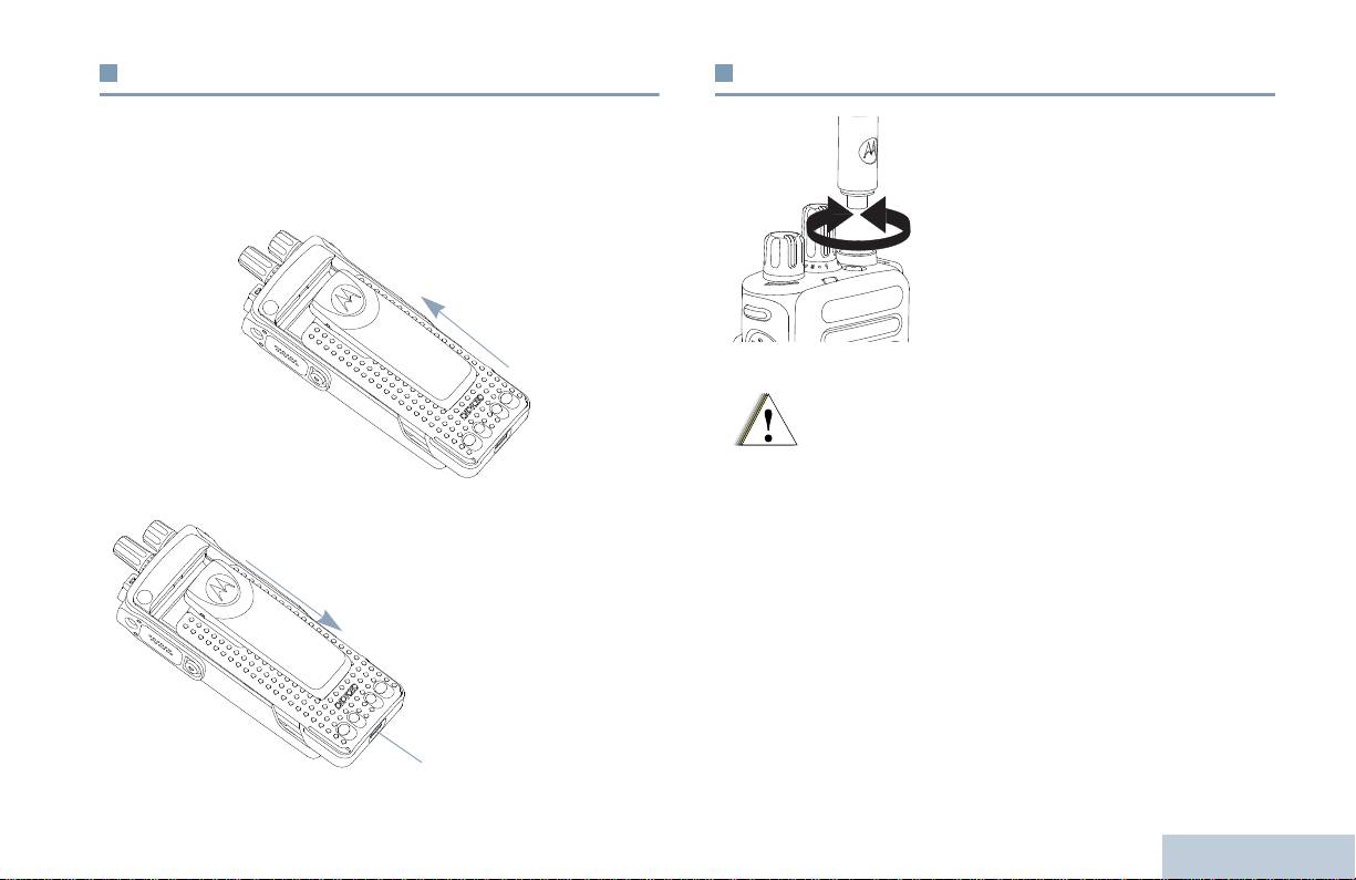
Installation de la batterie
Installation de l’antenne
Préparation de votre radio
Alignez la batterie sur les rainures situées au dos de la radio.
La radio étant éteinte, placez l’antenne
Appuyez avec fermeté sur la batterie et faites-la glisser vers le haut
dans son orifice et vissez dans le sens
jusqu’à ce que le verrou s’enclenche. Mettez le verrou de la batterie
horaire.
en position fermée.
Pour retirer l’antenne, tournez-la dans le
sens anti-horaire.
Pour retirer la
batterie, éteignez
votre radio. Placez
le verrou de la
batterie sur la
position ouverte.
Maintenez la
batterie et
faites-la glisser vers
le bas pour la sortir
des rainures.
3
Français
Verrou de
la batterie
S’il s’avérait nécessaire de remplacer une antenne,
vous devez uniquement utiliser une antenne
MOTOTRBO. Tout autre type d’antenne
endommagera votre radio.
Avertissement
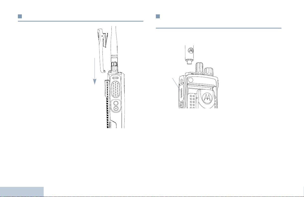
Fixation de la pince de ceinture
Pose du cache du connecteur universel
(protection anti-poussière)
Alignez les rainures de la
Le connecteur universel se situe sur le côté Antenne de la radio. Il
pince à celles de la batterie et
permet de brancher des accessoires MOTOTRBO.
appuyez vers le bas jusqu’à ce
Insérez le petit crochet de
que vous entendiez un clic.
maintien (qui se trouve à
l’extrémité du cache) dans
Pour retirer la pince de
l’emplacement correspondant
ceinture, appuyez sur son
en haut du connecteur
onglet en l’écartant de la
universel. Appuyez sur le
batterie. Pour plus de facilité,
cache en poussant vers le bas
utilisez une clé. Faites glisser
pour que l’onglet inférieur se
la pince vers le haut en
positionne correctement dans
l’écartant de la radio.
le connecteur RF.
Tournez la vis dans le sens
horaire pour verrouiller le
cache en position.
Pour retirer le cache du connecteur universel, appuyez sur le cache
et tournez la vis dans le sens anti-horaire.
Lorsque le connecteur universel n’est pas utilisé, il doit être protégé
par le cache anti-poussière.
Préparation de votre radio
4
Français
Connecteur
universel

Allumage de la radio
Réglage du volume
Préparation de votre radio
Tournez le bouton Marche/
Pour augmenter le niveau du volume, tournez le bouton Marche/
Arrêt – Volume dans le sens
Arrêt – Volume dans le sens horaire.
horaire jusqu’à ce que vous
entendiez un clic. Le témoin
est vert fixe.
Une brève tonalité retentit,
confirmant que l’auto-test à la
mise sous tension a réussi.
REMARQUE :
Il n'y aura aucune
tonalité à la mise sous
tension si la
fonction Tonalités/
avertissements a été
désactivée (voir Pour
activer/désactiver
les tonalités/avertissements à la page 37).
Pour le diminuer, tournez ce bouton dans le sens anti-horaire.
Si votre radio ne s’allume pas, vérifiez la batterie. Vérifiez qu’elle
REMARQUE : Votre radio peut être programmée pour respecter
est chargée et correctement installée. Si votre radio ne s’allume
un écart de volume minimal grâce auquel le
toujours pas, contactez votre fournisseur.
volume sonore ne peut pas être inférieur au
volume minimal programmé. Pour obtenir d’autres
Pour éteindre la radio, tournez ce bouton dans le sens anti-horaire
informations, veuillez consulter votre fournisseur
jusqu’à ce que vous entendiez un clic.
ou votre administrateur système.
5
Français

Identification des commandes
Prenez quelques instants pour lire les informations suivantes :
Commandes de la radio. . . . . . . . . . . . . . . . . . . . . . . . . . . .page 6
Boutons programmables . . . . . . . . . . . . . . . . . . . . . . . . . . .page 7
Alternat. . . . . . . . . . . . . . . . . . . . . . . . . . . . . . . . . . . . . . . . .page 8
Pour basculer entre les modes conventionnels
Analogique et Numérique. . . . . . . . . . . . . . . . . . . . . . . . .page 9
Connecter Site IP. . . . . . . . . . . . . . . . . . . . . . . . . . . . . . . .page 10
Capacity Plus . . . . . . . . . . . . . . . . . . . . . . . . . . . . . . . . . . .page 10
Linked Capacity Plus . . . . . . . . . . . . . . . . . . . . . . . . . . . . .page 11
Commandes de la radio
Sélecteur de canal
Marche/Arrêt – Volume
Témoin lumineux
Bouton latéral 1*
Alternat
Bouton latéral 2*
Bouton latéral 3*
Identification des commandes
Microphone
6
Français
1
2
3
4
5
6
7
8
Haut-parleur
Connecteur universel pour accessoires
Bouton d’urgence*
Antenne
* Ces boutons sont programmables.
1
12
2
11
10
3
4
9
5
8
6
7
9
10
11
12

Annonce vocale de canal – Émet les messages d’annonce vocale
Boutons programmables
de zone et de canal sur le canal courant. Cette fonction n’est pas
disponible lorsque la fonction Annonce vocale est désactivée.
Identification des commandes
Votre fournisseur peut programmer les boutons programmables
pour accéder directement à des fonctions ou à des groupes/
Urgence – Selon la programmation, cette fonction lance ou annule
canaux prédéfinis selon la durée de la pression :
un message ou un appel d’urgence.
• Pression courte – Appuyez sur le bouton et relâchez-le
Audio intelligent activé/désactivé – Active ou désactive la
immédiatement.
fonction Audio intelligent.
• Pression longue – Appuyez et maintenez enfoncé le bouton
‡
pendant la durée programmée.
Itinérance de site manuelle
*
– Lancer la recherche
• Maintien – Vous maintenez le bouton enfoncé.
manuelle de site.
REMARQUE : La durée programmée d’une pression s’applique à
CGA Micro activée/désactivée – Active ou désactive la
tous les paramètres et toutes les fonctions radio/
commande de gain automatique (CGA) du microphone interne.
utilitaires attribuables. Voir Fonctionnement du
Option non disponible pendant une session Bluetooth.
mode Urgence à la page 27 pour avoir des
Ecouter – Pour écouter l’activité sur un canal sélectionné.
informations supplémentaires sur la durée
programmée du bouton Urgence.
‡
Suppression de canal nuisible*
– Suppression temporaire d’un
canal indésirable dans la liste de balayage, sauf le canal
Fonctions attribuables
sélectionné. Le Canal sélectionné correspond à la combinaison
Canal/Zone sélectionnée par l’utilisateur à partir de laquelle le
TM
balayage a débuté.
Interrupteur audio Bluetooth
– Permet de basculer le routage
de l’audio entre le haut-parleur interne de la radio et l’accessoire
Accès par numérotation rapide –
Lance directement un
externe Bluetooth.
appel individuel ou de groupe prédéfini, un avertissement d’appel
Connecter Bluetooth – Lance une opération Chercher-connecter
ou un message texte rapide.
Bluetooth.
Fonction Carte d’options – Active ou désactive les fonctions de la
Déconnecter Bluetooth – Ferme toutes les connexions Bluetooth
carte d’options sur les canaux qui les utilisent.
actives entre votre radio et tous les dispositifs Bluetooth.
Renvoi d’appel – Active ou désactive la fonction Renvoi d’appel.
7
Français
* Non applicable en mode Capacity Plus
‡
Non applicable avec Linked Capacity Plus
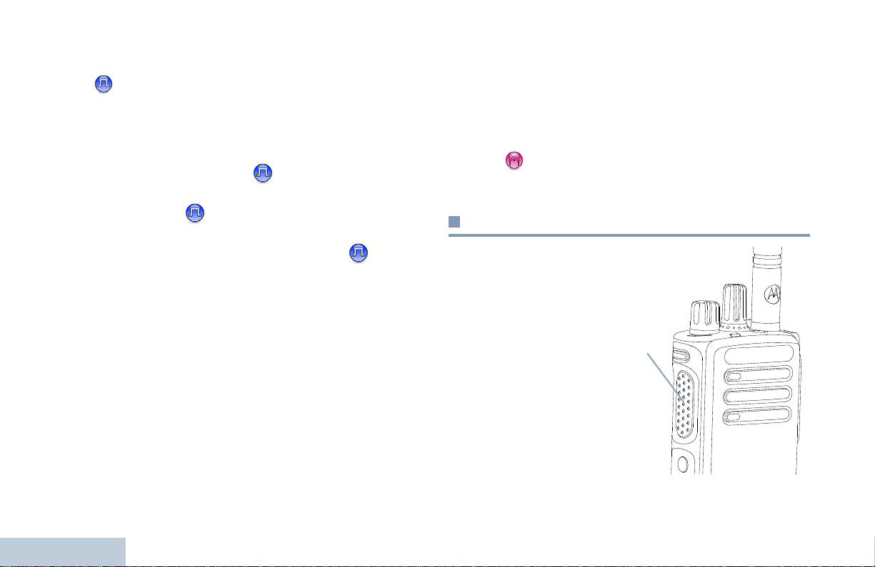
‡
Ecoute permanente*
– Pour écouter constamment le trafic sur un
Fonctions utilitaires ou paramètres attribuables
canal sélectionné jusqu’à ce que la fonction soit désactivée.
Toutes tonalités/avertissements – Pour activer ou désactiver
Secret –
Active ou désactive la fonction Secret.
toutes les tonalités et tous les avertissements.
‡
Relais/Direct
*
– Permet de basculer entre l’utilisation d’un relais
Niveau de puissance
– Pour basculer entre le niveau de
et la communication directe avec une autre radio.
puissance Haut et Bas.
‡
Balayage
*
– Marche/Arrêt de la fonction Balayage.
Squelch – Pour basculer entre le niveau de squelch Normal
Verrouillage site activé/désactivé
* – Activer ou désactiver
et Filtré.
l’itinérance de site automatique.
Contrôle de télémétrie –
Contrôle la broche de sortie sur une
Alternat
radio locale ou distante.
Alternat désactivé déporté Interruption d’émission –
L’Alternat est situé sur le
Arrête l’appel en cours interruptible pour libérer le canal.
côté de la radio et a deux
Annonce vocale activée/désactivée – Active ou désactive la
fonctions principales :
fonction Annonce vocale.
• Pendant un appel,
Émission activée par la voix (VOX) – Activer ou désactiver VOX.
l’Alternat permet
d’émettre vers d’autres
Zone – Permet d’effectuer une sélection dans une liste de zones.
radios ciblées par cet
appel.
Charge de la batterie – Le témoin lumineux indique le niveau de
charge actuel de la batterie.
Appuyez et maintenez
l’Alternat pour parler.
Relâchez l’Alternat pour
écouter.
Identification des commandes
Le microphone est
ouvert lorsque vous
appuyez sur l’Alternat.
8
Français
* Non applicable en mode Capacity Plus
‡
Non applicable avec Linked Capacity Plus
Alternat
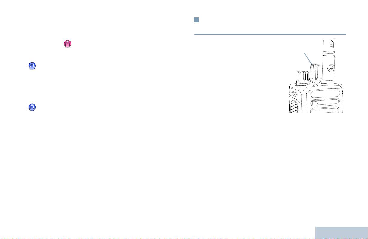
• Lorsqu’un appel n’est pas en cours, l’Alternat sert à lancer les
Pour basculer entre les modes
appels radio (voir Pour lancer un appel radio à la page 18).
conventionnels Analogique et Numérique
Identification des commandes
Selon la configuration, si la tonalité Parler autorisé ou la tonalité
locale Alternat est activée, attendez l’extinction de cette
Chaque canal de votre radio
tonalité courte pour parler.
peut être configuré comme
canal Analogique
conventionnel ou canal
Pendant, un appel, si la fonction d’indication Canal libre est
Numérique conventionnel.
activée (programmée par votre fournisseur), vous entendrez
Le sélecteur de canal vous
une brève tonalité d’avertissement lorsque le destinataire de
permet de basculer entre un
l’appel lâche l’Alternat. Cette tonalité confirme que le canal
canal analogique ou un canal
est libre et que vous pouvez parler.
numérique.
Selon que la radio est utilisée
Si votre appel est interrompu, vous entendez également une
sur un canal analogique ou
tonalité continue Parler non autorisé, signalant que vous
numérique, certaines
devez relâcher l’Alternat, par exemple lorsque votre radio
fonctions sont disponibles ou indisponibles.
reçoit un appel d’urgence.
Votre radio offre des fonctions disponibles dans les deux modes, à
savoir le mode analogique et le mode numérique. Les petites
différences de fonctionnement de ces deux modes n’ont AUCUNE
incidence sur les performances de votre radio.
REMARQUE : Votre radio bascule entre les deux modes
numérique et analogique pendant un balayage en
mode double (voir Balayage à la page 24).
9
Français
Sélecteur de canal

Vous ne pouvez pas manuellement ajouter ou supprimer une
Connecter Site IP
entrée dans la liste d’itinérance. Pour obtenir d’autres informations,
veuillez consulter votre fournisseur ou votre administrateur
Grâce à cette fonction, votre radio peut étendre ses
système.
communications conventionnelles au-delà de la couverture assurée
par un seul site en lui permettant de se connecter à différents sites
disponibles sur un réseau IP (Internet Protocol).
Capacity Plus
Lorsque la radio passe de la zone de couverture d’un site à celle
d’un autre site, elle se connecte au relais du deuxième site pour
Capacity Plus est une configuration en mode Ressources
envoyer et recevoir des appels/des données. Selon la
partagées sur site unique du système radio MOTOTRBO. Elle
programmation, cette transition est automatique ou manuelle.
permet d’utiliser un groupe de canaux pour supporter des centaines
Si cette fonction est configurée en mode automatique, la radio
d’utilisateurs et jusqu’à 254 Groupes. Capacity Plus permet à votre
recherche tous les sites disponibles dès que le signal qu’elle reçoit
radio d’utiliser efficacement les canaux programmés disponibles en
est faible ou lorsqu’elle ne peut plus détecter le signal émis par le
mode Relais.
site actuel. Elle se verrouille alors sur le relais qui fournit la
Les icônes des fonctions qui ne sont pas applicables dans Capacity
meilleure valeur RSSI (Indicateur de niveau de signal reçu).
Plus ne sont pas disponibles dans le menu. Vous entendrez une
Si cette fonction est configurée en mode manuel, la radio cherche à
tonalité d’indication négative si vous tentez d’utiliser une fonction
se connecter au prochain site figurant dans la liste d’itinérance et
non applicable à Capacity Plus en appuyant sur un bouton
qui est à sa portée (mais dont le signal n'aura pas nécessairement
programmable.
la valeur la plus élevée) et se verrouille sur ce site.
Votre radio comporte aussi des caractéristiques qui sont
disponibles en mode Numérique conventionnel : Connecter Site IP,
REMARQUE : le balayage et l’itinérance ne peuvent jamais être
Capacity Plus et Linked Capacity Plus. Les petites différences de
activés simultanément sur un même canal.
fonctionnement entre ces deux modes n’ont AUCUN effet sur les
Les canaux qui utilisent cette fonction peuvent être ajoutés à une
performances de votre radio.
liste de d’itinérance spécifique.
La radio cherche le ou les canaux de
Pour obtenir d’autres informations sur cette configuration, veuillez
la liste d’itinérance pendant l’opération d’itinérance automatique
consulter votre fournisseur ou votre administrateur système.
pour identifier le site ayant la plus forte valeur RSSI.
Identification des commandes
Une liste d’itinérance peut contenir jusqu’à 16 canaux (incluant le
canal Sélectionné).
10
Français

Les canaux qui utilisent Linked Capacity Plus peuvent être ajoutés
Linked Capacity Plus
à une liste d’itinérance spécifique. La radio explore ces canaux
pendant l’opération d’itinérance automatique pour identifier le site
Identification des commandes
Linked Capacity Plus est une configuration multi-canal multi-site
ayant la plus forte valeur RSSI.
des ressources partagées du système radio MOTOTRBO, qui
combine les meilleures configurations Capacity Plus et Connecter
REMARQUE : Vous ne pouvez pas manuellement ajouter ou
Site IP.
supprimer une entrée dans la liste d’itinérance.
Grâce à Linked Capacity Plus, votre radio peut étendre ses
Pour obtenir d’autres informations, veuillez
communications à ressources partagées au-delà de la couverture
consulter votre fournisseur ou votre administrateur
assurée par un seul site en lui permettant de se connecter à
système.
différents sites disponibles sur un réseau IP (Internet Protocol).
Comme avec Capacity Plus, les icônes des caractéristiques non
Cette configuration apporte en outre une augmentation de la
utilisables avec Linked Capacity Plus ne sont pas accessibles dans
capacité en combinant et en utilisant efficacement les canaux
le menu. Vous entendez une tonalité d’indication négative si vous
programmés disponibles sur les différents sites accessibles.
appuyez sur un bouton programmable pour accéder à une fonction
Lorsque la radio passe de la zone de couverture d’un site à celle
indisponible sur Linked Capacity Plus.
d’un autre site, elle se connecte au relais du deuxième site pour
Pour obtenir d’autres informations sur cette configuration, veuillez
envoyer et recevoir des appels/des données. Selon la
consulter votre fournisseur ou votre administrateur système.
programmation, cette transition est automatique ou manuelle.
Si cette fonction est configurée en mode automatique, la radio
recherche tous les sites disponibles dès que le signal qu’elle reçoit
est faible ou lorsqu’elle ne peut plus détecter le signal émis par le
site actuel. Elle se verrouille alors sur le relais qui fournit la
meilleure valeur RSSI (Indicateur de niveau de signal reçu).
Si cette fonction est configurée en mode manuel, la radio cherche à
se connecter au prochain site figurant dans la liste d’itinérance et
qui est à sa portée (mais dont le signal n'aura pas nécessairement
la valeur la plus élevée) et se verrouille sur ce site.
11
Français
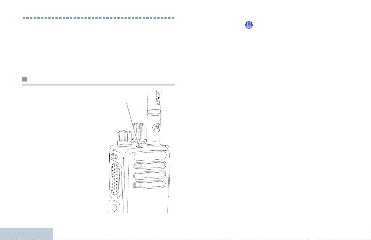
Vert clignotant double
– Réception d’un appel ou de données
Identifying Status Indicators
avec la fonction Secret .
Jaune fixe
– La radio écoute un canal conventionnel. Signale
Votre radio signale son statut opérationnel par l’intermédiaire des
également un niveau de charge de batterie suffisant lorsque
indicateurs suivants :
l’utilisateur appuie sur le bouton Charge de la batterie.
Témoin lumineux . . . . . . . . . . . . . . . . . . . . . . . . . . . . . . . .page 12
Jaune clignotant
– La radio balaie et écoute le trafic sur les
Tonalités audio . . . . . . . . . . . . . . . . . . . . . . . . . . . . . . . . . .page 13
canaux ou reçoit un avertissement d’appel, ou tous les canaux
Tonalités d’indication . . . . . . . . . . . . . . . . . . . . . . . . . . . . .page 13
Linked Capacity Plus sont occupés.
Clignotant jaune double
– La radio n’est plus connectée au relais
Témoin lumineux
en mode Capacity Plus ou Linked Capacity Plus, tous les canaux
Capacity Plus et Linked Capacity Plus sont occupés, la fonction
Le témoin lumineux signale le
Itinérance automatique est activée, la radio recherche activement
statut opérationnel de votre radio.
un nouveau site. Indique également que la radio n’a pas encore
Rouge clignotant – La radio
répondu à un avertissement d’appel de groupe, ou qu’elle est
verrouillée.
émet et le niveau de charge de la
batterie est faible, ou elle reçoit
une communication d’urgence,
REMARQUE : Dans un mode conventionnel, lorsque la radio
ou l’auto-test à la mise sous
détecte une communication en cours sur le canal,
tension a échoué.
le témoin vert clignote. Par la nature du protocole
Vert fixe
– La radio s’allume ou
numérique, cette activité peut ou non avoir un effet
émet. Signale également un
sur le canal programmé.
niveau de charge de batterie
maximal lorsque l’utilisateur
Avec Capacity Plus et Linked Capacity Plus, aucun
appuie sur le bouton Charge de
voyant LED ne signale la détection d’une
la batterie.
communication radio.
Vert clignotant
– Réception d’un
Identifying Status Indicators
appel ou de données sans la
fonction Secret, ou détection
d’une communication radio.
12
Français
Témoin lumineux
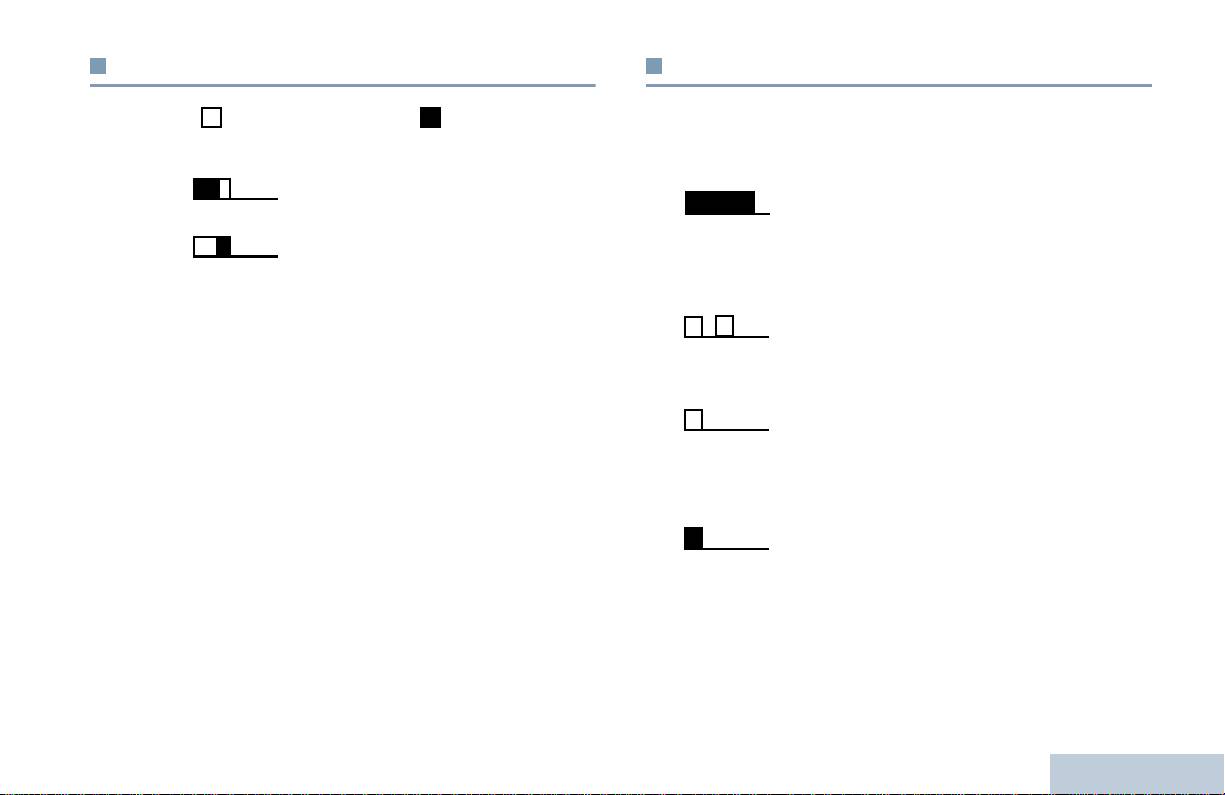
Tonalités d’indication
Tonalités audio
Identifying Status Indicators
Les tonalités d’avertissement vous informent de l’état de la radio ou
Tonalité aiguë Tonalité basse
des réponses de la radio en fonction des données reçues.
Tonalité continue
Son uniforme. Retentit en continu jusqu’à
Tonalité positive
la fin de l’état.
Tonalité négative
Tonalité
Tonalité périodique selon la durée
périodique
programmée. La tonalité est répétée à
intervalles réguliers.
Tonalité répétitive
Un seul son est répété jusqu’à ce que
l’utilisateur le désactive.
Tonalité
Un son retentit une fois pendant une
momentanée
courte période programmée.
13
Français

Sélectionner un canal
Réception et envoi d’appels
Les communications sont envoyées et reçues sur un canal. Selon
Dès que vous comprenez la configuration de votre radio portable
la configuration de votre radio, chaque canal peut avoir été
MOTOTRBO, vous êtes prêt à l’utiliser.
programmé différemment pour supporter différents groupes
Ce guide de la navigation vous aidera à vous familiariser avec les
d’utilisateurs ou leur procurer diverses fonctions. Après avoir
fonctions d’appel de base :
sélectionné la zone requise, sélectionnez le canal sur lequel vous
Pour sélectionner une Zone. . . . . . . . . . . . . . . . . . . . . . . .page 14
voulez émettre ou recevoir.
Sélectionner un canal. . . . . . . . . . . . . . . . . . . . . . . . . . . . .page 14
Pour recevoir et répondre à un appel. . . . . . . . . . . . . . . . .page 15
Pour lancer un appel radio. . . . . . . . . . . . . . . . . . . . . . . . .page 18
Pour arrêter un appel radio . . . . . . . . . . . . . . . . . . . . . . . .page 21
Mode Direct . . . . . . . . . . . . . . . . . . . . . . . . . . . . . . . . . . . .page 21
Fonctions d’écoute. . . . . . . . . . . . . . . . . . . . . . . . . . . . . . .page 22
Pour sélectionner une Zone
Une zone est un groupe de canaux. Votre radio supporte un
nombre maximal de 32 canaux et 2 zones, avec un maximum de 16
canaux par zone.
Procédure :
Procédure :
Tournez le sélecteur de canal pour sélectionner le canal avec
1 Appuyez sur le bouton préprogrammé Zone.
l’identité ou la désignation de groupe active.
2 Vous entendez une tonalité d’indication positive, confirmant que
la radio est passée de la Zone 1 à la Zone 2.
Réception et envoi d’appels
OU
Vous entendez une tonalité d’indication négative, confirmant
que la radio est passée de la Zone 2 à la Zone 1.
14
Français
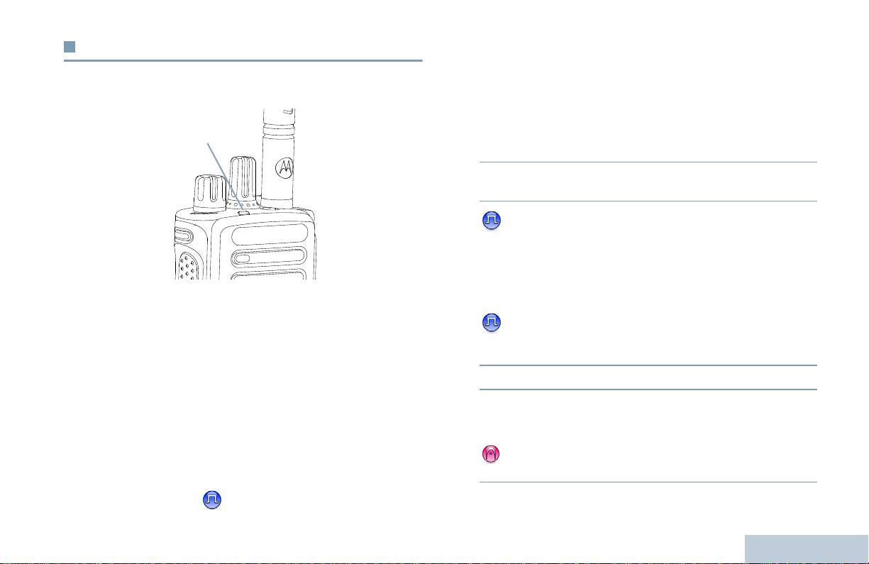
Pour recevoir et répondre à un appel
Pour recevoir et répondre à un appel de groupe
Pour recevoir un appel provenant d’un groupe d’utilisateurs, votre
Réception et envoi d’appels
Lorsque le canal, l’identité d’un utilisateur ou d’un groupe est
radio doit être configurée comme membre de ce groupe.
affichée, vous pouvez recevoir et répondre à des appels.
Procédure :
1 Le témoin clignote en vert. Votre radio reçoit et l’appel entrant
est entendu dans le haut-parleur.
2 Pour parler, tenez la radio en position verticale entre 2,5 et
5,0 cm de votre bouche.
3 Si la fonction d’indication Canal libre est activée, vous
entendrez une brève tonalité d’avertissement lorsque l’Alternat
de la radio émettrice est relâché. Cette tonalité confirme que le
canal est libre et que vous pouvez parler.
Appuyez sur l’Alternat pour prendre l’appel.
Le témoin est vert fixe lorsque la radio émet. Il est vert clignotant
OU
lorsqu’elle reçoit.
Si la fonction Interruption vocale est activée, appuyez sur
REMARQUE : Le témoin vert fixe est allumé lorsque la radio
l’Alternat pour interrompre l’appel en cours de la radio
émet. Il clignote en vert par éclats doubles lorsque
émettrice afin de libérer le canal pour pouvoir parler/répondre.
la radio reçoit un appel utilisant la fonction Secret.
4 Le témoin est vert fixe.
Pour décrypter un appel protégé par la fonction
5 Attendez la tonalité Parler autorisé (si cette option est activée)
Secret, votre radio doit avoir la même clé privée,
et parlez distinctement dans le microphone.
OU la même Valeur Clé et la même ID Clé
OU
(programmées par votre fournisseur) que la radio
émettrice (la radio qui vous appelle).
Attendez l’extinction de la tonalité locale Alternat (si cette
option est activée) et parlez distinctement dans le microphone.
Pour plus d’informations, voir Secret à la
page 31.
15
Français
Témoin lumineux

6 Relâchez l’Alternat pour écouter.
4 Appuyez sur l’Alternat pour prendre l’appel. Le témoin est vert
fixe.
7 En l’absence d’activité vocale pendant une durée
prédéterminée, la communication est automatiquement
5 Attendez la tonalité Parler autorisé (si cette option est activée)
annulée.
et parlez distinctement dans le microphone.
6 Relâchez l’Alternat pour écouter.
Voir Pour lancer un appel de groupe à la page 18.
7 En l’absence d’activité vocale pendant une durée
Pour recevoir et répondre à un appel
prédéterminée, la communication est automatiquement
individuel
annulée.
Un appel individuel est un appel provenant d’une seule radio
8 Vous entendez une tonalité courte.
individuelle communiquant avec une autre radio individuelle.
Voir Pour lancer un appel individuel à la page 19.
Procédure :
Lorsque vous recevez un appel individuel :
1 Le témoin clignote en vert. Votre radio reçoit et l’appel entrant
est entendu dans le haut-parleur.
2 Pour parler, tenez la radio en position verticale entre 2,5 et
5,0 cm de votre bouche.
3 Si la fonction d’indication Canal libre est activée, vous
entendrez une brève tonalité d’avertissement lorsque l’Alternat
de la radio émettrice est relâché. Cette tonalité confirme que le
canal est libre et que vous pouvez parler.
OU
Si la fonction Interruption vocale est activée, appuyez sur
l’Alternat pour interrompre l’appel en cours de la radio
émettrice afin de libérer le canal pour pouvoir parler/répondre.
Réception et envoi d’appels
16
Français

Voir Pour lancer un appel sélectif à la page 19 pour effectuer un
Pour recevoir et répondre à un appel sélectif
appel selectif.
Un appel sélectif est un appel provenant d’une seule radio
Réception et envoi d’appels
individuelle communiquant avec une autre radio individuelle.
Pour recevoir un appel général
C’est un appel individuel sur un système analogique.
Un Appel général est un appel lancé par une radio individuelle à
Procédure :
destination de toutes les radios présentes sur le canal sélectionné.
Un appel général sert à diffuser des annonces importantes, dont les
Lorsque vous recevez un appel sélectif :
utilisateurs doivent tenir compte.
1 Le témoin vert clignote.
Procédure :
2 Tenez la radio en position verticale entre 2,5 et 5,0 cm de votre
Lorsque vous recevez un appel général :
bouche. Votre radio reçoit et l’appel entrant est entendu dans le
1 Une tonalité retentit et le témoin clignote en vert. Votre radio
haut-parleur.
reçoit et l’appel entrant est entendu dans le haut-parleur.
3 Si la fonction d’indication Canal libre est activée, vous entendez
2 En l’absence d’une activité vocale prolongée au-delà d’une
une brève tonalité d’avertissement lorsque le destinataire de
durée prédéterminée, la communication est automatiquement
votre appel lâche l’Alternat. Cette tonalité confirme que le
annulée. Aucun délai prédéterminé n’est inséré avant la fin d’un
canal est libre et que vous pouvez parler.
appel général.
4 Appuyez sur l’Alternat pour prendre l’appel. Le témoin est vert
Si la fonction d’indication Canal libre est activée, vous
fixe.
entendrez une brève tonalité d’avertissement lorsque l’Alternat
5 Attendez la tonalité Parler autorisé (si cette option est activée)
de la radio émettrice est relâché. Cette tonalité confirme que le
et parlez distinctement dans le microphone.
canal est libre et que vous pouvez parler.
6 Relâchez l’Alternat pour écouter.
Vous ne pouvez pas répondre à un appel général.
7 En l’absence d’activité vocale pendant une durée
REMARQUE : Si vous changez de canal pendant la réception
prédéterminée, la communication est automatiquement
d’un appel général, il sera interrompu.
annulée.
Vous ne pouvez utiliser aucun des boutons
préprogrammés avant la fin d’un appel général.
8 Vous entendez une tonalité courte.
17
Français

Pour lancer un appel radio
Pour lancer un appel avec le sélecteur de canal
Après avoir sélectionné un canal, vous pouvez sélectionner
Pour lancer un appel de groupe
l’identité ou la désignation d’un utilisateur ou d’un groupe avec les
Pour lancer un appel destiné à un groupe d’utilisateurs, votre radio
boutons suivants :
doit être configurée comme membre de ce groupe.
• Le sélecteur de canal
Procédure :
• Un bouton Accès par numérotation rapide programmé
1 Sélectionnez le canal correspondant à l’identité ou à la
désignation de groupe actif. Voir Sélectionner un canal à la
REMARQUE : La fonction Secret doit être activée sur le canal pour
page 14.
que votre radio puisse émettre en utilisant le
OU
cryptage. Seules les radios ayant la même clé
Appuyez sur le bouton programmé avec Accès par
privée OU la même Valeur Clé et la même ID Clé
numérotation rapide.
que votre radio peuvent décrypter la transmission.
2 Tenez la radio en position verticale entre 2,5 et 5,0 cm de votre
Pour plus d’informations, voir Secret à la
bouche.
page 31.
3 Appuyez sur l’Alternat pour lancer l’appel. Le témoin est vert
fixe.
La fonction Accès par numérotation rapide vous
4 Attendez la tonalité Parler autorisé (si cette option est activée)
permet de lancer très facilement des appels de
et parlez distinctement dans le microphone.
groupe ou individuels vers une identité spécifique.
OU
Cette fonctionnalité peut être attribuée à un bouton
Attendez l’extinction de la tonalité locale Alternat (si cette
programmable avec une pression longue ou courte.
option est activée) et parlez distinctement dans le microphone.
Vous pouvez UNIQUEMENT attribuer une seule
identité à un bouton d’accès par numérotation
5 Relâchez l’Alternat pour écouter. Lorsque la radio cible répond,
rapide. Plusieurs boutons peuvent être
le témoin clignote en vert.
programmés pour utiliser l’accès par numérotation
6 Si la fonction d’indication Canal libre est activée, vous
rapide.
entendrez une brève tonalité d’avertissement lorsque le
Réception et envoi d’appels
destinataire de l’appel lâche l’Alternat. Cette tonalité confirme
que le canal est libre et que vous pouvez parler. Appuyez sur
l’Alternat pour parler.
18
Français

OU
Appuyez sur le bouton programmé avec Accès par
En l’absence d’activité vocale pendant une durée
numérotation rapide.
prédéterminée, la communication est automatiquement
Réception et envoi d’appels
2 Tenez la radio en position verticale entre 2,5 et 5,0 cm de votre
annulée.
bouche.
3 Appuyez sur l’Alternat pour lancer l’appel. Le témoin est vert
Pour lancer un appel individuel
fixe.
Vous pouvez recevoir un appel et/ou répondre à un Appel
4 Attendez la tonalité Parler autorisé (si cette option est activée)
individuel provenant d’un poste autorisé, mais votre radio
et parlez distinctement dans le microphone.
doit être programmée pour que vous puissiez lancer un
5 Relâchez l’Alternat pour écouter. Lorsque la radio cible répond,
Appel individuel.
le témoin clignote en vert.
Il existe deux types d’appels individuels. Dans le premier cas, la
6 Si la fonction d’indication Canal libre est activée, vous
présence de la radio cible est vérifiée avant d’établir l’appel. Dans
entendrez une brève tonalité d’avertissement lorsque le
le deuxième cas, l’appel est établi et lancé immédiatement.
destinataire de l’appel lâche l’Alternat. Cette tonalité confirme
Votre fournisseur ne peut programmer qu’un seul de ces deux
que le canal est libre et que vous pouvez parler. Appuyez sur
types d’appel sur votre radio.
l’Alternat pour parler.
OU
Vous entendez une tonalité d’indication négative lorsque vous
En l’absence d’activité vocale pendant une durée
lancez un appel individuel avec le bouton Accès par numérotation
prédéterminée, la communication est automatiquement
rapide ou le sélecteur de canaux, si cette caractéristique n’est pas
annulée.
activée.
7 Vous entendez une tonalité courte.
Utilisez la fonction Message texte rapide ou Avertissement d’appel
pour contacter une radio individuelle. Pour plus d’informations, voir
les Caractéristiques de la messagerie de texte à la page 30 ou
Pour lancer un appel sélectif
Fonctionnement des avertissements d’appel à la page 26.
Exactement comme un appel individuel. Vous pouvez recevoir et/
Procédure :
ou répondre à un appel sélectif provenant d’une radio individuelle
autorisée, mais votre radio doit être programmée pour lancer un
1 Sélectionnez le canal correspondant à l’identité ou à la
appel sélectif.
désignation de groupe actif. Voir Sélectionner un canal à la
page 14.
OU
19
Français

Procédure :
Pour lancer un appel général
1 Sélectionnez le canal correspondant à l’identité ou à la
Cette fonction vous permet d’émettre vers tous les utilisateurs
désignation de groupe actif. Voir Sélectionner un canal à la
présents sur le canal. Votre radio doit être programmée pour vous
page 14.
permettre d’utiliser cette fonction.
2 Tenez la radio en position verticale entre 2,5 et 5,0 cm de votre
Procédure :
bouche.
1 Sélectionnez le canal correspondant à l’identité ou à la
3 Appuyez sur l’Alternat pour lancer l’appel. Le témoin est vert
désignation de groupe actif. Voir Sélectionner un canal à la
fixe.
page 14.
4 Attendez la tonalité Parler autorisé (si cette option est activée)
2 Tenez la radio en position verticale entre 2,5 et 5,0 cm de votre
et parlez distinctement dans le microphone.
bouche.
5 Relâchez l’Alternat pour écouter. Lorsque la radio cible répond,
3 Appuyez sur l’Alternat pour lancer l’appel. Le témoin est vert
le témoin clignote en vert.
fixe.
6 Si la fonction d’indication Canal libre est activée, vous
4 Attendez la tonalité Parler autorisé (si cette option est activée)
entendrez une brève tonalité d’avertissement lorsque le
et parlez distinctement dans le microphone.
destinataire de l’appel lâche l’Alternat. Cette tonalité confirme
OU
que le canal est libre et que vous pouvez parler. Appuyez sur
l’Alternat pour parler.
Attendez l’extinction de la tonalité locale Alternat (si cette
OU
option est activée) et parlez distinctement dans le microphone.
En l’absence d’activité vocale pendant une durée
Les utilisateurs du canal ne peuvent pas répondre à un appel
prédéterminée, la communication est automatiquement
général.
annulée.
7 Vous entendez une tonalité courte.
Réception et envoi d’appels
20
Français

Mode Direct
Pour arrêter un appel radio
Réception et envoi d’appels
Vous pouvez continuer à communiquer lorsque votre relais n’est
Cette fonction vous permet d’interrompre un appel individuel ou de
pas disponible (hors service ou hors de portée) mais que d’autres
groupe pour libérer le canal utilisé. Par exemple, un utilisateur a
radios sont à portée de votre radio. Ce mode de communication
appuyé par inadvertance sur l’Alternat et le microphone de la radio
poste à poste sans relais est appelé mode Direct.
reste constamment ouvert.
Votre radio doit être programmée pour vous permettre d’utiliser
REMARQUE : Cette fonction n’est pas applicable dans Capacity
cette fonction.
Plus et Linked Capacity Plus.
Procédure :
Procédure :
Après avoir sélectionné le canal requis :
1 Appuyez sur le bouton programmé Alternat désactivé déporté
1 Appuyez sur le bouton programmé Relais/Direct.
Interruption d’émission.
2 Vous entendez une tonalité d’indication positive, confirmant que
2 Attendez l’accusé de réception.
la radio est en mode Direct.
OU
3 Vous entendez une tonalité d’indication positive, confirmant que
Vous entendez une tonalité d’indication négative, confirmant
le canal est libre.
que la radio est en mode Relais.
OU
Vous entendez une tonalité d’indication négative, indiquant que
La configuration Direct est conservée après la mise hors tension de
le canal n’a pas pu être libéré.
la radio.
Votre radio déclenche une tonalité d’indication négative jusqu’à ce
que vous relâchiez l’Alternat, si la radio émet un appel interruptible
arrêté par cette fonction. Lorsque l’appel est interrompu sur une
radio avec écran, l’écran affiche
Appel interrompu
.
21
Français

Fonctions d’écoute
Ecoute permanente
Cette fonction vous permet d’écouter en permanence l’activité sur
le canal sélectionné.
Pour écouter un canal
La fonction Ecoute vous permet de vérifier qu’un canal est libre
REMARQUE : Cette fonction n’est pas applicable dans Capacity
avant d’émettre.
Plus et Linked Capacity Plus.
REMARQUE : Cette fonction n’est pas applicable dans Capacity
Procédure :
Plus et Linked Capacity Plus.
1 Appuyez sur le bouton préprogrammé Ecoute permanente.
Procédure :
2 Une tonalité d’avertissement retentit et le témoin est jaune fixe.
1 Maintenez le bouton préprogrammé Ecoute et écoutez l’activité
3 Appuyez sur le bouton programmé Écoute permanente pour
en cours.
quitter ce mode.
2 Selon la programmation de votre radio, vous entendez de
4 Une tonalité d’avertissement retentit et le témoin s’éteint.
l’activité ou un silence total.
3 Lorsque vous entendez du “bruit blanc” (c-à-d. que le canal est
libre), appuyez sur l’Alternat pour parler. Le témoin est jaune
fixe.
Réception et envoi d’appels
22
Français

Listes de balayage
Fonctions avancées
Les listes de balayage sont créées et attribuées à des canaux/
Fonctions avancées
Utilisez ce guide de navigation pour en savoir plus sur les fonctions
groupes spécifiques. Votre radio recherche une activité vocale en
évoluées disponibles sur votre radio :
balayant la séquence des canaux/groupes spécifiée dans la liste de
Listes de balayage . . . . . . . . . . . . . . . . . . . . . . . . . . . . . . page 23
balayage.
Balayage . . . . . . . . . . . . . . . . . . . . . . . . . . . . . . . . . . . . . page 24
Votre radio peut utiliser jusqu’à 250 listes de balayage, chacune
Paramètres des indicateurs d’appel. . . . . . . . . . . . . . . . . page 26
comptant au maximum 16 membres par liste. Chaque liste de
Fonctionnement des avertissements d’appel. . . . . . . . . . page 26
balayage peut contenir des entrées analogiques et numériques.
Fonctionnement du mode Urgence . . . . . . . . . . . . . . . . . page 27
REMARQUE : Cette fonction n’est pas applicable dans Capacity
Caractéristiques de la messagerie de texte . . . . . . . . . . . page 30
Plus et Linked Capacity Plus.
Secret. . . . . . . . . . . . . . . . . . . . . . . . . . . . . . . . . . . . . . . . page 31
Commandes multi-sites . . . . . . . . . . . . . . . . . . . . . . . . . . page 32
Travailleur isolé . . . . . . . . . . . . . . . . . . . . . . . . . . . . . . . . page 33
Fonction de verrouillage avec mot de passe . . . . . . . . . . page 33
Bluetooth . . . . . . . . . . . . . . . . . . . . . . . . . . . . . . . . . . . . . page 34
Configuration / Informations . . . . . . . . . . . . . . . . . . . . . . . page 36
23
Français

Balayage
Pour lancer et arrêter le balayage
Procédure :
Lorsque vous lancez un balayage, votre radio lit en boucle la liste
de balayage préprogrammée à la recherche d’une activité vocale
1 Appuyez sur le bouton préprogrammé Balayage.
sur les canaux de la liste.
OU
Le témoin clignote en jaune.
Appuyez sur le sélecteur de canal pour sélectionner un canal
dont la fonction Balayage Auto est activée.
Pendant un balayage en mode double (analogique et numérique),
si vous êtes en train de communiquer sur un canal numérique, et
2 Lorsque le balayage est activé, le témoin jaune clignote et vous
que votre radio détecte et s’arrête sur un canal analogique, elle
entendez une tonalité d’indication positive.
passe automatiquement du mode numérique au mode analogique
OU
pendant la durée de l’appel. Dans le cas contraire, elle effectue
Lorsque la fonction Balayage est désactivée, le témoin s’éteint
cette opération en sens inverse.
et vous entendez une tonalité d’indication négative.
Il existe deux types de balayage :
• Balayage du canal principal (Manuel) : Votre radio balaie tous
Pour répondre à une émission pendant un
les canaux/groupes de la liste. Lorsque votre radio passe en
balayage
mode de balayage et – selon sa configuration – débute
Pendant le balayage, votre radio s’arrête sur un canal/groupe où
automatiquement par le dernier canal/groupe “actif” balayé ou le
elle détecte de l’activité. Elle reste sur ce canal pendant une durée
canal sur lequel le balayage a démarré.
programmée appelée « délai de maintien ».
• Balayage auto (Automatique) : Votre radio lance
Procédure :
automatiquement le balayage dès que vous sélectionnez un
1 Tenez la radio en position verticale entre 2,5 et 5,0 cm de votre
canal/groupe sur lequel la fonction Balayage automatique est
activée.
bouche.
REMARQUE : Cette fonction n’est pas applicable dans Capacity
Si la fonction d’indication Canal libre est activée, vous
Plus et Linked Capacity Plus.
entendrez une brève tonalité d’avertissement lorsque l’Alternat
de la radio émettrice est relâché. Cette tonalité confirme que le
Fonctions avancées
canal est libre et que vous pouvez parler.
2 Appuyez sur l’Alternat pendant le délai de maintien. Le témoin
est vert fixe.
24
Français

3 Attendez la tonalité Parler autorisé (si cette option est activée)
Pour rétablir un canal nuisible
et parlez distinctement dans le microphone.
Procédure :
OU
Fonctions avancées
Pour restaurer un canal nuisible supprimé, vous pouvez choisir
Attendez l’extinction de la tonalité locale Alternat (si cette
l’une des méthodes suivantes :
option est activée) et parlez distinctement dans le microphone.
• Éteignez et rallumez votre radio, OU
4 Relâchez l’Alternat pour écouter.
• Arrêtez et redémarrez un balayage avec le bouton programmé
Balayage, OU
5 Si vous ne répondez pas pendant la durée de maintien, le
balayage se poursuit sur d’autres canaux/groupes.
• Changez de canal avec le sélecteur de canal.
Pour supprimer un canal nuisible
Scan vote
Si un canal génère constamment du bruit, des interférences ou des
appels indésirables (appelé « canal nuisible »), vous pouvez
La fonction Scan vote vous procure une couverture
temporairement le supprimer de la liste de balayage.
remarquablement étendue dans les zones où plusieurs stations de
base émettent des informations identiques sur différents canaux
Cette fonction ne peut pas être appliquée au canal désigné comme
analogiques.
canal sélectionné.
Votre radio balaie les canaux analogiques de ces stations de base
Procédure :
et applique un processus de vote pour sélectionner le signal le plus
1 Lorsque votre radio s’arrête sur un canal nuisible, appuyez sur
puissant. Ensuite, votre radio ouvre le squelch pour recevoir
le bouton préprogrammé Supprimer canal nuisible jusqu’à ce
l’émission de la station de base élue.
qu’une tonalité retentisse.
Le témoin jaune clignote pendant le Scan vote.
2 Relâchez le bouton Supprimer canal nuisible. Le canal
Pour répondre à une émission pendant un scan de vote, suivez la
nuisible est supprimé.
procédure indiquée dans la section Pour répondre à une
émission pendant un balayage à la page 24.
25
Français

Paramètres des indicateurs d’appel
2 Pour répondre à un appel individuel, appuyez sur l’Alternat
pendant les quatre (4) secondes qui suivent la réception d’un
avertissement d’appel.
Vous pouvez activer ou désactiver les sonneries de réception
d’appel individuel (voir Pour activer/désactiver les tonalités/
avertissements à la page 37).
Pour lancer un avertissement d’appel avec le
bouton Accès par numérotation rapide
Volume croissant de la tonalitè des alarmes
Procédure :
Votre fournisseur peut programmer votre radio pour qu’elle vous
1 Appuyez sur le bouton programmé Accès par numérotation
avertisse en continu qu’un appel reçu attend une réponse. Votre
rapide pour lancer un avertissement d’appel à l’identité
poste augmente automatiquement le volume de la tonalité pendant
prédéfinie.
une période prédéterminée.
2 Le témoin est vert fixe pendant que votre radio envoie
Cette caractéristique est appelée Avertissement croissant.
l’avertissement d’appel.
3 Lorsque l’accusé de réception de l’avertissement d’appel est
reçu, deux bips retentissent.
Fonctionnement des avertissements
OU
d’appel
Lorsque la radio ne reçoit pas d’accusé de réception de
l’avertissement d’appel, une tonalité basse retentit.
La fonction Avertissement d’appel vous permet d’avertir un
utilisateur de vous rappeler dès que cela lui sera possible. Cette
fonction est accessible par un bouton programmé Accès par
numérotation rapide.
Pour recevoir et répondre à un avertissement
d’appel
Procédure :
Lorsque vous recevez un avertissement d’appel :
Fonctions avancées
1 Vous entendez une tonalité répétitive. Le témoin clignote en
jaune.
26
Français

En outre, chaque alarme est disponible en deux types :
Fonctionnement du mode Urgence
• Normal – La radio envoie l’alarme et la confirme par ses
Fonctions avancées
Une alarme d’urgence sert à signaler une situation critique. Vous
indicateurs audio et/ou visuel.
pouvez déclencher une Urgence à tout instant, quel que soit l’état
• Silencieuse – La radio émet un signal d’alarme sans indications
en cours, même s’il y a de l’activité sur le canal utilisé.
visuelles ou audibles. La radio reçoit des appels sans produire
Votre revendeur peut régler la durée de la pression sur le bouton
d’audio dans le haut-parleur, jusqu’à ce que l’utilisateur appuie
Urgence, sauf pour la pression longue qui est similaire à toutes les
sur l’Alternat pour lancer l’appel.
autres touches :
• Silencieux avec voix – La radio envoie l’alarme sans aucune
indication audible ou visuelle, mais les appels entrants peuvent
• Pression courte – Entre 0,05 et 0,75 secondes
être entendus dans le haut-parleur de la radio.
• Pression longue – Entre 1,00 et 3,75 secondes
Une seule des deux alarmes d’urgence ci-dessus peut être
Le bouton Urgence est attribué à la fonction Urgence activée/
attribuée au bouton préprogrammé Urgence.
désactivée. Pour obtenir d’autres informations sur le
fonctionnement du bouton Urgence attribué, consultez votre
Pour envoyer un message d’alarme d’urgence
fournisseur local.
Cette fonction vous permet d’envoyer une alarme d’urgence, un
Si la pression courte sur le bouton Urgence est attribuée à
signal non-vocal, qui déclenche un avertissement sur un groupe de
l’activation du mode Urgence, la pression longue sur ce bouton est
radios.
attribuée à la désactivation du mode Urgence.
Procédure :
Si la pression longue sur le bouton Urgence est attribuée à
1 Appuyez sur le bouton programmé Urgence activée.
l’activation du mode Urgence, la pression courte sur ce bouton est
attribuée à la désactivation du mode Urgence.
2 Le témoin est vert fixe.
3 Lorsque la radio reçoit un accusé de réception d’une alarme
Votre radio supporte trois modes d’alarme d’urgence :
d’urgence, la tonalité d’urgence retentit. Le témoin clignote en
• Alarme d’urgence
vert.
OU
• Alarme d’urgence avec appel
Si la radio ne reçoit pas un accusé de réception d’une alarme
• Alarme d’urgence suivie d’un appel vocal
d’urgence, et lorsque toutes les relances sont épuisées, une
tonalité basse retentit.
27
Français

4 La radio quitte le mode Alarme d’urgence.
7 Relâchez l’Alternat pour écouter.
8 Lorsque le canal est libre, une tonalité d’avertissement courte
Si le mode Silencieux est activé, votre radio ne donnera aucune
indication visuelle ou sonore pendant l’utilisation du mode Urgence.
retentit ( si la Tonalité Indication Canal libre a été activée).
Appuyez sur l’Alternat pour parler.
OU
Pour envoyer un message d’alarme d’urgence
Lorsque l’appel est terminé, appuyez sur le bouton programmé
avec un appel
Urgence désactivée pour quitter le mode Urgence.
Cette fonction vous permet d’envoyer une alarme d’urgence à un
groupe de radios. Après accusé de réception par une des radios du
Si le mode Silencieux est activé, votre radio ne donnera aucune
groupe, le groupe de radios peut communiquer sur un canal
indication visuelle ou sonore pendant l’utilisation du mode Urgence,
d’urgence programmé.
et son haut-parleur restera silencieux même si elle reçoit un ou
Procédure :
plusieurs appels, et cela jusqu’à ce que vous appuyiez sur
1 Appuyez sur le bouton programmé Urgence activée.
l’Alternat pour lancer l’appel en mode Urgence.
2 Le témoin est vert fixe.
Si le mode Silencieux avec voix est activé, votre radio ne donnera
aucune indication visuelle ou sonore pendant l’utilisation du mode
3 Lorsque la radio reçoit un accusé de réception d’une alarme
d’urgence, la tonalité d’urgence retentit. Le témoin clignote en
Urgence, mais elle laissera entendre les appels entrants dans son
vert.
haut-parleur. Les indicateurs ne réapparaissent que lorsque vous
appuyez sur l’Alternat pour appeler ou répondre.
4 Tenez la radio en position verticale entre 2,5 et 5,0 cm de votre
bouche.
Pour envoyer un message d’alarme d’urgence
5 Appuyez sur l’alternat pour lancer l’appel. Le témoin est vert
suivi d’un appel vocal
fixe.
Cette fonction vous permet d’envoyer une alarme d’urgence à un
6 Attendez la tonalité Parler autorisé (si cette option est activée)
groupe de radios. Le microphone de votre radio est
et parlez distinctement dans le microphone.
automatiquement ouvert et vous permet de communiquer avec le
OU
groupe de radios sans appuyer sur votre Alternat.
Fonctions avancées
Attendez l’extinction de la tonalité locale Alternat (si cette
Cet état du microphone activé est aussi appelé « micro ouvert ».
option est activée) et parlez distinctement dans le microphone.
28
Français

Si le mode Cycle Urgence est activé sur votre radio, le cycle
Après expiration de la période « Micro ouvert », et si le mode
alternatif entre le micro ouvert et la réception d’appel est activé
Cycle Urgence est désactivé.
pendant une durée programmée.
Fonctions avancées
5 Pour émettre à nouveau, appuyez sur l’Alternat.
REMARQUE : Pendant le mode Cycle Urgence, les appels reçus
OU
sont entendus dans le haut-parleur de la radio.
Appuyez sur le bouton Urgence désactivée pour quitter le
mode Urgence.
Si vous appuyez sur l’Alternat pendant la période de réception
programmée, vous entendez la tonalité de non autorisation,
Si le mode Silencieux est activé, votre radio ne donnera aucune
indiquant que vous devez relâcher l’Alternat. La radio ignore
indication visuelle ou sonore pendant l’utilisation du mode Urgence,
l’Alternat et reste en mode Urgence.
et son haut-parleur restera silencieux même si elle reçoit un ou
REMARQUE : Si vous appuyez sur l’Alternat pendant que le
plusieurs appels, et cela jusqu’à ce que la période de transmission
micro est ouvert, et que vous le maintenez après
Micro ouvert programmée expire, et que vous appuyiez sur
expiration de la période « Micro ouvert », la radio
l’Alternat.
continue d’émettre jusqu’à ce que vous relâchiez
Si le mode Silencieux avec voix est activé, votre radio ne donnera
l’Alternat.
aucune indication visuelle ou sonore pendant l’utilisation du mode
Procédure :
Urgence, lorsque vous appelez avec le Micro ouvert, mais vous
1 Appuyez sur le bouton programmé Urgence activée.
entendrez l’audio dans le haut-parleur lorsque la radio cible répond
après expiration de la période de transmission Micro ouvert
2 Le témoin est vert fixe.
programmée. Les indicateurs ne réapparaissent que lorsque vous
3 Après la tonalité, parlez distinctement dans le microphone.
appuyez sur l’Alternat.
Lorsque le “micro ouvert” est activé, la radio émet
REMARQUE : Si la demande d’Alarme d’urgence échoue, la radio
automatiquement sans que l'utilisateur n'ait besoin de toucher
ne tente pas de renvoyer la demande, elle entre
l’Alternat jusqu’à la fin de la période “micro ouvert”.
directement en mode de transmission Micro ouvert.
Pendant l’émission, le témoin est vert fixe.
4 La radio arrête automatiquement l’émission lorsque la durée du
cycle alternatif entre le micro ouvert et la réception d’appel
expire et si le mode Cycle Urgence est activé.
OU
29
Français

Pour relancer un mode Urgence
Caractéristiques de la messagerie de
texte
REMARQUE : Cette caractéristique est uniquement applicable à
la radio qui envoie l’Alarme d’urgence.
Ceci peut arriver dans deux cas :
Pour envoyer un message texte rapide
Grâce à un bouton programmable, vous pouvez envoyer des
• Vous changez le canal pendant que la radio est en mode
messages textes rapides préprogrammés par votre fournisseur.
Urgence. Cette action annule le mode Urgence. Si la fonction
Alarme d’urgence est activée sur le nouveau canal, la radio
Procédure :
relance le mode Urgence.
1 Appuyez sur le bouton programmé Accès par numérotation
• Vous appuyez sur le bouton programmé Urgence activée
rapide pour envoyer un message texte rapide à une identité
pendant que la radio est en train d’activer le mode Urgence ou
prédéfinie.
d’émettre en mode Urgence. Cette action annule l’état en cours
2 Le témoin est vert fixe.
et relance le mode Urgence.
3 Deux bips confirment que le message a été correctement
Pour quitter le Mode Urgence
envoyé.
OU
REMARQUE : Cette caractéristique est uniquement applicable à
Une tonalité basse indique que le message ne peut pas être
la radio qui envoie l’Alarme d’urgence.
envoyé.
Votre radio quitte le mode Urgence dans l’un des trois cas suivants:
• La radio reçoit un accusé de réception d’alarme d’urgence (pour
Alarme urgence uniquement), OU
• Un télégramme de sortie d’urgence est reçu, OU
• La radio a utilisé le nombre total de tentatives d’envoi d’une
alarme, OU
• L’utilisateur appuie sur le bouton Urgence désactivée.
Fonctions avancées
REMARQUE : Si votre radio s’éteint, le mode Urgence est annulé.
Le mode Urgence ne sera pas automatiquement
rétabli à la prochaine mise sous tension de la radio.
30
Français

Le témoin vert fixe est allumé lorsque la radio émet. Il clignote
Secret
rapidement lorsqu’elle reçoit une transmission utilisant la fonction
Secret.
Fonctions avancées
Lorsque cette fonction est activée, elle protège les utilisateurs
REMARQUE : La fonction Secret n’est pas disponible sur certains
contre les possibilités d’écoute par des personnes non-autorisées
modèles. Pour obtenir d’autres informations,
sur un canal grâce à une solution de brouillage logicielle. Les
veuillez consulter votre fournisseur ou votre
éléments de signalisation et d’identification des utilisateurs ne sont
administrateur système.
pas cryptés.
Procédure :
La fonction Secret doit être activée sur le canal pour que la radio
Appuyez sur le bouton programmé Secret pour activer ou
puisse émettre en utilisant le cryptage, mais cela n’est pas
désactiver cette fonction.
nécessaire pour recevoir une communication. Lorsque la radio est
sur un canal programmé pour utiliser la fonction Secret, elle peut
recevoir des émissions en clair, comme à l’accoutumée.
Il existe deux types de fonctions Secret :
• Secret base
• Secret amélioré
Un SEUL de ces deux types de fonction Secret peut être
programmé sur une radio.
Pour décrypter un appel voix ou données protégé par la fonction
Secret, votre radio doit avoir la même clé privée (pour la fonction
Secret base) OU la même Valeur Clé et la même ID Clé (pour la
fonction Secret amélioré) que la radio émettrice.
Si votre radio reçoit un appel crypté qui utilise une clé privée
différente, OU une Valeur Clé et ID Clé différentes, vous entendrez
une transmission brouillée (Secret base) ou aucun son (Secret
amélioré).
31
Français

Arrêter une recherche de site automatique
Commandes multi-sites
Lorsque la radio recherche activement un nouveau site :
Ces caractéristiques sont applicables lorsque le canal actuel de
Procédure :
votre radio fait partie d’une configuration Connecter Site IP ou
Linked Capacity Plus.
1 Appuyez sur le bouton programmé Verrouillage site activé/
désactivé.
Pour plus d’informations sur ces configurations, consultez
Connecter Site IP à la page 10 et Linked Capacity Plus à la
2 Une tonalité retentit et le témoin s'éteint.
page 11.
Lancer une recherche de site manuelle
Lancer une recherche de site automatique
Procédure :
REMARQUE : La radio recherche uniquement un autre site si le
1 Appuyez sur le bouton programmé Itinérance de site
signal qu'elle reçoit est faible ou lorsqu'elle ne peut
manuelle.
plus détecter le signal émis par le site actuel. Tant
que l'Indicateur de niveau de signal reçu (RSSI) est
2 Une tonalité retentit et le témoin clignote en vert.
fort, la radio reste sur le site actuel.
3 Vous entendez une tonalité d'indication positive et le voyant
Procédure :
s'éteint, indiquant que la radio est verrouillée sur un site.
1 Appuyez sur le bouton programmé Verrouillage site activé/
OU
désactivé.
Vous entendez une tonalité d'indication négative et le voyant
s'éteint, indiquant que la radio ne peut pas se verrouiller sur un
2 Une tonalité retentit.
site.
3 Le voyant jaune clignote rapidement lorsque la radio recherche
activement un nouveau site, et s'éteint lorsque la radio se
verrouille sur un site.
La radio lance aussi une recherche de site automatique (le site est
déverrouillé) pendant une émission de données ou une pression
Fonctions avancées
sur l’Alternat, si le canal actuel (un canal multi-site avec une liste
d’itinérance jointe) est hors de portée.
32
Français

Travailleur isolé
Fonction de verrouillage avec mot de
passe
Fonctions avancées
Cette fonction envoie une alarme d’urgence lorsque la radio reste
inutilisée, par exemple si l’utilisateur n’appuie pas sur une touche
Lorsqu’elle est activée, cette fonction vous permet d’accéder à
ou ne tourne pas le sélecteur de canal avant expiration d’une durée
votre radio en entrant un mot de passe pendant la mise sous
prédéterminée.
tension. Utilisez le sélecteur de canal et les trois boutons latéraux
Après expiration de ce délai, la radio avertit l’utilisateur en
pour saisir le mot de passe (voir Commandes de la radio à la
produisant une tonalité d’indication.
page 6):
Si l’utilisateur ne confirme pas qu’il a entendu cette tonalité en
• Les positions 1 à 9 du sélecteur de canal représentent les
appuyant sur l’une des touches avant expiration du délai de rappel,
chiffres 1 à 9 et la position 10 représente le chiffre 0.
la radio envoie une alarme d’urgence.
• Les boutons latéraux 1 à 3 représentent les chiffres 1 à 3.
Une seule alarme d’urgence peut être associée à cette fonction :
Accès à la radio avec mot de passe
• Alarme d’urgence
Procédure :
• Alarme d’urgence avec appel
Allumez la radio.
• Alarme d’urgence suivie d’un appel vocal
1 Vous entendez une tonalité continue.
La radio reste en mode Urgence et autorise les messages vocaux
2 Appuyez sur le sélecteur de canal pour sélectionner le premier
jusqu’à la prochaine action de l’utilisateur. Pour quitter le mode
chiffre du mot de passe.
Urgence, voir la section Fonctionnement du mode Urgence à la
3 Appuyez sur le bouton latéral 1, 2 ou 3 pour saisir chaque
page 27.
chiffre restant du mot de passe. Une tonalité d’indication
positive retentit pour chaque pression sur un bouton latéral.
REMARQUE : Cette fonction est uniquement disponible sur les
Lorsque vous saisissez le deuxième chiffre du mot de passe, la
radios programmées à cet effet. Pour obtenir
radio ignore ensuite toute modification du sélecteur de canal.
d’autres informations, veuillez consulter votre
fournisseur ou votre administrateur système.
4 Lorsque vous avez saisi le dernier chiffre du mot passe, votre
radio vérifie automatiquement sa validité.
Si le mot de passe est correct :
Votre radio s’allume. Voir Allumage de la radio à la page 5.
OU
33
Français

Bluetooth
Si le mot de passe est incorrect :
Vous entendez une tonalité continue. Répétez les étapes 1 à 3.
Cette fonction vous permet d’utiliser votre radio avec un dispositif
OU
(accessoire) Bluetooth sur une connexion Bluetooth. Votre radio
Après le troisième mot de passe incorrect, la radio est
supporte les dispositifs Bluetooth de marque Motorola et d’autres
verrouillée. Une tonalité retentit et le témoin jaune clignote
marques disponibles sur le marché.
double.
Bluetooth offre une portée de 10 mètres avec une visibilité directe.
Votre radio est en état verrouillé pendant 15 minutes, elle répond
Pour bénéficier de cette portée, aucun obstacle ne doit gêner la
uniquement aux commandes du bouton Marche/Arrêt - Volume.
communication entre votre radio et votre dispositif Bluetooth.
REMARQUE : La radio verrouillée ne peut recevoir aucun appel,
Il est déconseillé de laisser votre radio en pensant que votre
incluant les appels d’urgence.
accessoire Bluetooth fonctionnera de manière normale lorsque ces
deux dispositifs sont séparés.
Déverrouillage de la radio
Lorsque la limite de réception approche, la voix et la qualité sonore
se détériorent et les hachures sont de plus en plus fréquentes. Pour
Procédure :
corriger ce problème, rapprochez votre radio et votre dispositif
Attendez 15 minutes. Répétez les étapes 1 à 4 dans Accès à la
Bluetooth (à moins de dix mètres) pour rétablir la réception audio
radio avec mot de passe à la page 33.
normale. Sur votre radio, la puissance maximale de la fonction
OU
Bluetooth est de 2,5 mW (4 dBm) avec une portée de dix mètres.
Allumez la radio si vous l’avez éteinte alors qu’elle était verrouillée
Votre radio peut supporter jusqu’à trois connexions Bluetooth
après un mot de passe incorrect.
simultanées avec des dispositifs Bluetooth tous différents. Par
1 Une tonalité retentit et le témoin jaune clignote double.
exemple, une oreillette, un scanner et un dispositif de commande
d’Alternat. Des connexions avec plusieurs accessoires Bluetooth
2 Attendez 15 minutes. Répétez les étapes 1 à 4 dans Accès à la
d’un même type ne sont pas possibles.
radio avec mot de passe à la page 33.
Veuillez consulter le manuel d’utilisation de votre dispositif
Lorsque vous allumez votre radio, elle relance le délai de 15
Bluetooth pour connaître ses capacités intégrales.
minutes d’attente sur état verrouillé.
Fonctions avancées
34
Français

Recherche et connexion à un dispositif Bluetooth
Pour déconnecter un dispositif Bluetooth
Procédure :
Procédure :
Fonctions avancées
Allumez votre dispositif Bluetooth et mettez-le en mode
1 Appuyez sur le bouton programmé Déconnecter Bluetooth.
Appariement. Consultez le manuel d’utilisation du dispositif
Bluetooth.
2 Une tonalité d’indication positive retentit après la déconnexion.
1 Sur votre radio, appuyez sur le bouton programmé Connecter
Bluetooth.
Pour basculer le routage audio
2 Une tonalité retentit et le témoin jaune clignote.
Vous pouvez basculer le routage de l’audio entre le haut-parleur
interne de la radio et l’accessoire externe Bluetooth.
3 D’autres étapes peuvent être nécessaires sur votre dispositif
Procédure :
Bluetooth pour terminer l’appariement avec votre radio.
Consultez le manuel d’utilisation du dispositif Bluetooth.
1 Appuyez sur le bouton programmé Interrup. audio BT.
4 Si l’opération réussit, une tonalité retentit.
2 Une tonalité retentit lorsque le routage audio a changé.
OU
Si l’opération ne réussit pas, une tonalité d’indication négative.
Vous ne devez pas éteindre votre dispositif Bluetooth pendant
l’opération de recherche et de connexion, sinon l’opération sera
annulée.
Votre radio se connecte à l’accessoire Bluetooth qui est à portée
avec le signal le plus fort ou qui a été connecté au cours d’une
session précédente.
REMARQUE : Pour permettre l’appariement de certains
dispositifs avec votre radio, il peut être nécessaire
de programmer un code PIN sur votre radio.
Contactez votre fournisseur pour obtenir d’autres
informations.
35
Français

Procédure :
Configuration / Informations
1 Appuyez sur le bouton préprogrammé Niveau de puissance.
2 Vous entendez une tonalité d’indication positive, confirmant que
Pour régler le niveau de squelch
la radio émet en puissance basse.
OU
Vous pouvez régler le niveau de squelch de votre radio pour filtrer
Vous entendez une tonalité d’indication négative, confirmant
les appels indésirables (ayant un signal insuffisant) ou des canaux
que la radio émet en puissance haute.
dont le bruit de fond est supérieur à la normale.
Réglages : Normal est la valeur par défaut. Filtré permet de filtrer
les appels (indésirables) et/ou le bruit de fond. Avec cette option,
Pour activer et désactiver la fonction Carte
certains appels émis par des sites éloignés peuvent être exclus.
d’options
Procédure :
Un canal peut supporter jusqu’à six fonctions de carte d’options.
Pour obtenir d’autres informations, veuillez consulter votre
1 Appuyez sur le bouton préprogrammé Squelch.
fournisseur ou votre administrateur système.
2 Vous entendez une tonalité d’indication positive, confirmant que
Procédure :
votre radio utilise le squelch filtré.
Appuyez sur le bouton programmé Carte d’options activée/
OU
désactivée pour activer ou désactiver cette fonction.
Vous entendez une tonalité d’indication négative, confirmant
que votre radio utilise le squelch normal.
Pour activer et désactiver la fonction Émission
activée par la voix (VOX)
Pour régler le niveau de puissance
Cette fonction vous permet de lancer des appels commandés par la
Vous pouvez régler le niveau de puissance de votre radio en
voix en mode mains libres sur un canal programmé. La radio émet
sélectionnant Haut ou Bas pour chaque canal.
automatiquement pendant une durée programmée, chaque fois
que le microphone de l’accessoire VOX détecte la voix d’un
Réglages : Haut supporte la communication avec des radios qui
utilisateur.
peuvent être considérablement éloignées de vous. Bas supporte la
communication avec des radios qui se trouvent à proximité.
Une pression sur l’Alternat, pendant que la radio émet, désactive
Fonctions avancées
la fonction VOX. Pour rétablir la fonction VOX, choisissez l’une des
méthodes suivantes :
• Éteignez et rallumez votre radio, OU
36
Français

• Changez de canal avec le sélecteur de canaux, OU
Pour vérifier le niveau de charge de la batterie
• Suivez la procédure ci-dessous.
Votre radio vous permet de savoir quel est le niveau de charge
Fonctions avancées
actuel de sa batterie.
REMARQUE : Seuls certains modèles peuvent activer et
désactiver cette fonction. Pour obtenir d’autres
Réglages : Le témoin jaune fixe indique un niveau de charge
informations, veuillez consulter votre fournisseur
moyen. Le témoin vert fixe indique un niveau de charge maximal.
ou votre administrateur système.
Voir aussi Témoin lumineux à la page 12.
Procédure :
Procédure :
Appuyez sur le bouton programmé VOX pour activer ou désactiver
Appuyez sur le bouton préprogrammé Niveau batterie. Le témoin
cette fonction.
lumineux indique le niveau de charge actuel.
Si la tonalité Parler autorisé est activée, utilisez un mot déclencheur
pour lancer l’appel. Attendez la fin de la tonalité Parler autorisé et
Annonce vocale
parlez distinctement dans le microphone.
Cette fonction permet d’indiquer par audio le canal ou la zone
attribuée par l’utilisateur ou une pression sur un bouton
Pour activer/désactiver les tonalités/
programmable. L’indication audio peut être personnalisée par
avertissements
l’utilisateur. Cette fonction est particulièrement utile lorsque
Si nécessaire, vous pouvez activer/désactiver toutes les tonalités et
l’utilisateur ne peut pas aisément lire l’écran de la radio.
tous les avertissements de votre radio (sauf l’avertissement
Pour activer et désactiver la fonction Annonce vocale, suivez les
d’urgence entrant).
instructions ci-dessous.
Procédure :
Procédure :
1 Appuyez sur le bouton préprogrammé Toutes tonalités.
Appuyez sur le bouton préprogrammé Annonce vocale.
2 Vous entendez une tonalité d’indication positive, confirmant que
toutes les tonalités sont activées.
OU
Vous entendez une tonalité d’indication négative, confirmant
que toutes les tonalités sont désactivées.
37
Français

Audio intelligent
Votre radio ajuste automatiquement le volume audio en fonction du
bruit de l’environnement, incluant les sources de bruit mobiles et
fixes. Cette fonction est uniquement dédiée à la réception et ne
concerne pas l’émission audio.
REMARQUE : Cette caractéristique n’est pas disponible pendant
une session Bluetooth.
Pour activer et désactiver la fonction Audio intelligent, suivez les
instructions ci-dessous.
Procédure :
Appuyez sur le bouton programmé Audio intelligent pour activer
ou désactiver cette fonction.
GPS
Le système de positionnement global (Global Positioning System –
GPS) est un système de navigation par satellites qui permet de
déterminer la position exacte d’une radio.
Procédure :
Appuyez sur le bouton programmé GPS pour activer ou désactiver
cette fonction.
Fonctions avancées
38
Français

La garantie de capacité
Garantie des batteries et des
La garantie de capacité couvre 80 % de la capacité de charge nominale
Garantie des batteries et des chargeurs
chargeurs
pendant la durée de la garantie du Produit
.
Batteries Lithium-ion (Li-lon) ou
12 mois
La garantie de fabrication
Nickel-métal-hydrure (NiMH)
La garantie de fabrication couvre les défauts de fabrication intervenant
Batteries IMPRES, si exclusivement utilisées
18 mois
pendant des utilisations et des opérations d’entretien normales
.
avec des chargeurs IMPRES
Toutes les batteries MOTOTRBO deux (2) ans
Chargeurs IMPRES (simples et multiples, sans
deux (2) ans
écran)
Chargeurs IMPRES (multiples avec écran) une (1) année
39
Français

modification de cette garantie sauf par écrit et signée par un
responsable de MOTOROLA.
Garantie limitée
En l’absence d’un accord séparé entre MOTOROLA et l’acquéreur
utilisateur final original, MOTOROLA ne garantit pas l’installation,
PRODUITS DE COMMUNICATION MOTOROLA
l’entretien ou la maintenance du Produit.
MOTOROLA ne peut pas être tenu responsable d’aucun équipement
I. OBJET ET DURÉE DE LA GARANTIE :
fourni par un tiers et connecté à ou utilisé avec le Produit, ou d’aucune
MOTOROLA SOLUTIONS, INC. (“MOTOROLA”) garantit les produits
utilisation conjointe avec le Produit ; tout équipement tiers est
de communication fabriqués par MOTOROLA listés ci-dessous contre
expressément exclu de la présente garantie. Comme chaque système
les défauts de fabrication et des matériaux dans des conditions
capable d’utiliser le Produit est unique, MOTOROLA ne peut pas être
normales d’utilisation et d’entretien pendant la durée indiquée à partir
tenu responsable de la portée, de la couverture ou du fonctionnement
de la date d’achat
:
du système qui reste donc exclu de cette garantie.
Radios portables numériques,
deux (2) années
II. DISPOSITIONS GENERALES :
gamme DP
Cette garantie décrit les responsabilités de MOTOROLA liées au
Produits accessoires (à l’exclusion
une (1) année
Produit. Le seul remède offert par MOTOROLA et à son entière
des batteries et des chargeurs)
discrétion inclut la réparation ou le remplacement du Produit ou le
remboursement du prix d’achat. CETTE GARANTIE REMPLACE
MOTOROLA, à sa discrétion et gratuitement, réparera (avec des
TOUTES LES AUTRES GARANTIES EXPRESSES. LES GARANTIES
composants neufs ou reconditionnés), ou remplacera (avec un produit
IMPLICITES, INCLUANT SANS LIMITATION LES GARANTIES
neuf ou reconditionné), ou remboursera le prix d’achat du Produit
IMPLICITES DE QUALITÉ MARCHANDE, ET D'APTITUDE À UNE
pendant la période de garantie s’il a été retourné conformément aux
UTILISATION PARTICULIÈRE, SONT LIMITÉES À LA DURÉE DE
conditions de la présente garantie. Tous les composants/toutes les
CETTE GARANTIE LIMITÉE
. EN AUCUN CAS MOROTOLA NE PEUT
cartes de remplacement sont garantis pendant le reste de la période de
garantie originale. Tous les composants remplacés du Produit
ÊTRE TENU RESPONSABLE D’AUCUN DÉDOMMAGEMENT
deviennent la propriété de MOTOROLA.
SUPÉRIEUR AU PRIX D’ACHAT DU PRODUIT, LIÉ À UNE PERTE
D’UTILISATION, PERTE DE TEMPS, INCONVÉNIENTS, PERTE
Cette garantie limitée expresse est fournie par MOTOROLA à
COMMERCIALE, BÉNÉFICES OU GAINS PERDUS, OU AUTRES
l’acquéreur utilisateur final et original du Produit et ne peut pas être
Garantie limitée
DOMMAGES ACCESSOIRES, SPÉCIAUX, INDIRECTS CAUSÉS PAR
transférée ou attribuée à un quelconque autre tiers. Cette garantie est
L’UTILISATION OU L’IMPOSSIBILITÉ D’UTILISER CE PRODUIT,
la garantie complète du Produit fabriqué par MOTOROLA. MOTOROLA
DANS LA MESURE OÙ CETTE CONDITION EST AUTORISÉE PAR
n’accepte aucune obligation ou responsabilité liée à aucune addition ou
LA LOI.
40
Français

III. DROITS ACCORDÉS PAR LA LÉGISLATION
D)La rupture ou détérioration d’antenne indépendante d’un défaut de
fabrication d’origine.
NATIONALE :
E) Un Produit qui a subi des modifications non autorisées, un
Garantie limitée
CERTAINS ÉTATS N'AUTORISENT PAS L'EXCLUSION OU LA
démontage ou des réparations (incluant, sans limitation, l’ajout d’un
LIMITATION DES DOMMAGES ACCESSOIRES OU INDIRECTS, OU
équipement tiers) qui ont un impact négatif sur la performance du
UNE LIMITATION DE LA DURÉE D’APPLICATION D’UNE GARANTIE
Produit ou qui interfèrent avec les tests et l’inspection de garantie
IMPLICITE, AUQUEL CAS LA LIMITATION OU EXCLUSION
normale de MOTOROLA applicables au Produit pour vérifier
CI-DESSUS RISQUE DE NE PAS ÊTRE APPLICABLE.
l’authenticité du recours en garantie.
Cette garantie vous donne des droits légaux spécifiques ; vous pouvez
F) Un Produit dont le numéro de série a été effacé, altéré ou rendu
également avoir d'autres droits, qui varient selon le pays ou l’État
.
illisible.
G)Les batteries rechargeables, si :
IV. POUR UTILISER LE SERVICE DE LA GARANTIE :
(1) Un joint de cellule de batterie est rompu ou présente des signes
de violation.
Vous devez fournir un justificatif d’achat (indiquant la date d’achat et le
(2) Si une erreur de fonctionnement ou une détérioration est causée
numéro de série du Produit) pour bénéficier du service de garantie, et
par le chargement ou l’utilisation de la batterie dans un équipement
aussi livrer ou expédier le Produit, tous frais de transport et d’assurance
ou un service autre que le produit pour lequel cette batterie a été
payés, à un centre de maintenance sous garantie agréé. Le service de
conçue ou spécifiée.
garantie sera fourni par un des centres de maintenance sous garantie
agréés par MOTOROLA. Pour obtenir le service de la garantie, vous
H)Les frais de transport au centre de maintenance.
pouvez contacter en premier lieu le fournisseur qui vous a vendu le
I) Un Produit qui ne fonctionne pas conformément aux spécifications
Produit (revendeur ou fournisseur de serviceS de communication).
publiées par MOTOROLA ou à la certification FCC conforme à son
étiquetage et en vigueur pendant la période de distribution initiale du
Produit par MOTOROLA parce que son logiciel/firmware a subi une
V. CETTE GARANTIE NE COUVRE PAS :
modification non autorisée ou illégale.
A) Les erreurs de fonctionnement ou détériorations provoquées par une
J) Des rayures ou autres détériorations visuelles sur la surface du
utilisation non conforme à celle prévue par le fabricant.
Produit et qui n’ont aucun effet sur son fonctionnement.
B) Les erreurs de fonctionnement ou détériorations provoquées par une
K) Une usure et autres traces d’utilisation normales.
utilisation incorrecte, un accident, l’eau ou la négligence.
C)Les erreurs de fonctionnement ou détériorations provoquées par des
opérations inappropriées d’essai, d’utilisation, de maintenance,
d’installation, d’ajustement, ou tout type de modification.
41
Français

VI. DISPOSITIONS RELATIVES AU BREVET ET AU
MOTOROLA ne peut pas être tenu responsable d’aucune violation d’un
brevet par une combinaison réunissant un Produit ou composants
LOGICIEL :
fournis conformément aux présentes et un logiciel, équipement ou
MOTOROLA défendra à ses frais tout acquéreur utilisateur final contre
dispositif fourni par un tiers. En outre, MOTOROLA ne peut avoir
toute poursuite basée sur une prétendue violation par le Produit ou ses
aucune obligation ou responsabilité concernant l’utilisation d’un logiciel
composants d’un brevet déposé aux États-Unis. MOTOROLA prendra à
tiers ou équipement accessoire tiers et connecté à ou utilisé avec le
sa charge les coûts et les dédommagements imposés à l’acquéreur
Produit. Les dispositions ci-dessus constituent la totalité des
utilisateur final dans tous les cas de poursuite associés à de telles
responsabilités de MOTOROLA concernant tous les cas de violation de
demandes, mais cette défense et ces paiements seront uniquement
brevet par le Produit ou un de ses composants.
possibles si les conditions suivantes sont respectées :
La législation des États-Unis et d’autres pays réservent à MOTOROLA
A) MOTOROLA doit être informé rapidement par écrit par l’acquéreur
certains droits exclusifs sur les logiciels protégés par des droits d'auteur
concerné de l’existence d’une telle demande ;
au nom de MOTOROLA, y compris le droit exclusif de reproduire et de
B) MOTOROLA doit avoir le contrôle total de la défense, de toutes les
distribuer des copies des logiciels MOTOROLA. Un logiciel
négociations, du règlement ou accord final ; et
MOTOROLA peut uniquement être utilisé dans le Produit dans lequel il
C)Si le Produit ou certains de ses composants deviennent l’objet, ou
a été originellement installé par son fabricant, et ce logiciel dans ce
peuvent devenir l’objet selon le jugement de MOTOROLA, de
Produit ne peut pas être remplacé, copié, distribué, modifié de quelque
poursuite pour violation d’un brevet déposé aux États-Unis,
façon que ce soit, ou utilisé pour produire une autre version dérivée. Est
l’acquéreur doit autoriser MOTOROLA, à sa discrétion et à ses frais,
interdite toute autre utilisation telle que, sans limitation : altération,
de soit prendre les mesures nécessaires pour que l’acquéreur
modification, reproduction, distribution, ou ingénierie inverse des
continue d’avoir le droit d’utiliser le Produit ou ses composants ou de
logiciels MOTOROLA ou l’exécution des droits liés aux logiciels
les remplacer ou de les modifier afin d’éliminer les risques de
MOTOROLA. Les droits d'auteur ou les brevets de MOTOROLA ne
violation de brevet ou d’accorder à l’acquéreur un crédit
constituent ni ne donnent droit à aucune licence directement ou
correspondant à la valeur dépréciée du Produit ou de ses
indirectement, par préclusion ou autrement.
composants avec retour du Produit/des composants. La dépréciation
sera calculée sur la base d’un montant annuel fixe pendant la durée
VII. LÉGISLATION APPLICABLE :
de vie du Produit ou de ses composants telle que définie par
MOTOROLA.
Cette garantie est régie par la législation de l’Illinois, États-Unis.
Garantie limitée
42
Français

Comandi della radio . . . . . . . . . . . . . . . . . . . . . . . . . . . . 6
Indice
Funzioni di comando . . . . . . . . . . . . . . . . . . . . . . . . . . 6
Pulsanti programmabili . . . . . . . . . . . . . . . . . . . . . . . . . 7
Indice
Il presente Manuale per l’utente contiene tutte le
Funzioni assegnabili . . . . . . . . . . . . . . . . . . . . . . . . . 7
informazioni necessarie per utilizzare le ricetrasmittenti
Impostazioni assegnabili e utilità . . . . . . . . . . . . . . . . 8
portatili della serie MOTOTRBO.
Pulsante PTT (premere per parlare) . . . . . . . . . . . . . . . 8
Informazioni importanti sulla sicurezza . . . . . . . . . . . . . . iv
Commutazione tra le modalità convenzionali
Sicurezza del prodotto ed esposizione
analogica e digitale . . . . . . . . . . . . . . . . . . . . . . . . . . . 9
all’energia di radiofrequenza (RF) . . . . . . . . . . . . . . iv
Connessione IP Site . . . . . . . . . . . . . . . . . . . . . . . . . 10
Versione software . . . . . . . . . . . . . . . . . . . . . . . . . . . . . iv
Capacity Plus . . . . . . . . . . . . . . . . . . . . . . . . . . . . . . . 10
Linked Capacity Plus . . . . . . . . . . . . . . . . . . . . . . . . . 11
Informazioni sul copyright del software . . . . . . . . . . . .v
Indicatori di stato . . . . . . . . . . . . . . . . . . . . . . . . . . . . . 12
Precauzioni per l’uso . . . . . . . . . . . . . . . . . . . . . . . . . . vi
Indicatore LED . . . . . . . . . . . . . . . . . . . . . . . . . . . . . . 12
Nozioni preliminari . . . . . . . . . . . . . . . . . . . . . . . . . . . . .1
Toni di segnalazione . . . . . . . . . . . . . . . . . . . . . . . . . . 13
Uso del Manuale per l’utente . . . . . . . . . . . . . . . . . . . . .1
Toni audio . . . . . . . . . . . . . . . . . . . . . . . . . . . . . . . . . . 13
Informazioni da richiedere al distributore/
Ricezione e invio delle chiamate . . . . . . . . . . . . . . . . 14
amministratore di sistema . . . . . . . . . . . . . . . . . . . . . . .1
Selezione di una zona . . . . . . . . . . . . . . . . . . . . . . . . 14
Predisposizione della radio . . . . . . . . . . . . . . . . . . . . . .2
Selezione di un canale . . . . . . . . . . . . . . . . . . . . . . . . 14
Carica della batteria . . . . . . . . . . . . . . . . . . . . . . . . . . . .2
Ricezione e risposta a una chiamata radio . . . . . . . . . 15
Inserimento della batteria . . . . . . . . . . . . . . . . . . . . . . . .3
Ricezione e risposta a una chiamata di gruppo . . . 15
Montaggio dell’antenna . . . . . . . . . . . . . . . . . . . . . . . . .3
Ricezione e risposta a una chiamata privata . . . . . 16
Montaggio della clip per cintura . . . . . . . . . . . . . . . . . . .4
Ricezione e risposta a una chiamata selettiva . . . . 17
Montaggio del cappuccio del connettore
Ricezione di una chiamata generale . . . . . . . . . . . . 17
universale (cappuccio parapolvere) . . . . . . . . . . . . . . .4
Invio di una chiamata radio . . . . . . . . . . . . . . . . . . . . . 18
Accensione della radio . . . . . . . . . . . . . . . . . . . . . . . . . .5
Invio di una chiamata voce con il selettore
Regolazione del volume . . . . . . . . . . . . . . . . . . . . . . . . .5
di canale . . . . . . . . . . . . . . . . . . . . . . . . . . . . . . . . . 18
Invio di una chiamata di gruppo . . . . . . . . . . . . . . 18
i
Italiano

Invio di una chiamata privata . . . . . . . . . . . . . . . 19
Riavvio della modalità di emergenza . . . . . . . . . . . .30
Invio di una chiamata selettiva . . . . . . . . . . . . . .19
Uscita dalla modalità di emergenza . . . . . . . . . . . . .30
Invio di una chiamata generale . . . . . . . . . . . . . . . 20
Messaggi di testo . . . . . . . . . . . . . . . . . . . . . . . . . . . .30
Interruzione di una chiamata radio . . . . . . . . . . . . . . . 21
Invio di un messaggio predefinito . . . . . . . . . . . . . . .30
Comunicazione diretta . . . . . . . . . . . . . . . . . . . . . . . . . 21
Privacy . . . . . . . . . . . . . . . . . . . . . . . . . . . . . . . . . . . .31
Funzioni di monitoraggio . . . . . . . . . . . . . . . . . . . . . . . 22
Controlli multisito . . . . . . . . . . . . . . . . . . . . . . . . . . . . .32
Monitoraggio di un canale . . . . . . . . . . . . . . . . . . . . 22
Inizio della ricerca automatica del sito . . . . . . . . . . .32
Monitor permanente . . . . . . . . . . . . . . . . . . . . . . . . . 22
Fine della ricerca automatica del sito . . . . . . . . . . . .32
Inizio della ricerca manuale del sito . . . . . . . . . . . . .32
Funzioni avanzate . . . . . . . . . . . . . . . . . . . . . . . . . . . . . 23
Lavoratore solo . . . . . . . . . . . . . . . . . . . . . . . . . . . . . .33
Liste di scansione . . . . . . . . . . . . . . . . . . . . . . . . . . . . 23
Funzioni Blocco password . . . . . . . . . . . . . . . . . . . . . .33
Scansione . . . . . . . . . . . . . . . . . . . . . . . . . . . . . . . . . . 24
Accesso alla radio mediante password . . . . . . . . . .33
Inizio e fine della scansione . . . . . . . . . . . . . . . . . . . 24
Sblocco della radio . . . . . . . . . . . . . . . . . . . . . . . . . .34
Risposta a una trasmissione durante
Bluetooth . . . . . . . . . . . . . . . . . . . . . . . . . . . . . . . . . . .34
la scansione . . . . . . . . . . . . . . . . . . . . . . . . . . . . . . . 24
Ricerca e connessione a un dispositivo
Eliminazione del canale di disturbo . . . . . . . . . . . . . 25
Bluetooth . . . . . . . . . . . . . . . . . . . . . . . . . . . . . . . . .35
Ripristino del canale di disturbo . . . . . . . . . . . . . . . . 25
Disconnessione da un dispositivo Bluetooth . . . . . .35
Scansione selettiva . . . . . . . . . . . . . . . . . . . . . . . . . .25
Commutazione dell'instradamento dell'audio . . . . . .35
Impostazioni degli indicatori di chiamata . . . . . . . . . . . 26
Utilità . . . . . . . . . . . . . . . . . . . . . . . . . . . . . . . . . . . . . .36
Volume del tono per gli allarmi progressivi . . . . . . . 26
Impostazione del livello di squelch . . . . . . . . . . . . .36
Avvisi di chiamata . . . . . . . . . . . . . . . . . . . . . . . . . . . . 26
Impostazione del livello di potenza . . . . . . . . . . . . . .36
Ricezione e risposta a un avviso di chiamata . . . . . 26
Abilitazione e disabilitazione della funzionalità
Invio di un avviso di chiamata con il
della scheda opzioni . . . . . . . . . . . . . . . . . . . . . . . . .36
pulsante accesso rapido . . . . . . . . . . . . . . . . . . . . . 26
Attivazione e disattivazione della funzione VOX
Emergenza . . . . . . . . . . . . . . . . . . . . . . . . . . . . . . . . . 27
(trasmissione attivata dalla voce) . . . . . . . . . . . . . . .36
Invio di un allarme di emergenza . . . . . . . . . . . . . . . 27
Attivazione e disattivazione dei toni e degli
Indice
Invio di un allarme di emergenza con chiamata . . . . 28
avvisi . . . . . . . . . . . . . . . . . . . . . . . . . . . . . . . . . . . . .37
Invio di un allarme di emergenza con
Controllo dello stato di carica della batteria . . . . . . .37
successiva trasmissione voce . . . . . . . . . . . . . . . . . 28
ii
Italiano

Annuncio vocale . . . . . . . . . . . . . . . . . . . . . . . . . . . .37
Audio intelligente . . . . . . . . . . . . . . . . . . . . . . . . . . .38
GPS . . . . . . . . . . . . . . . . . . . . . . . . . . . . . . . . . . . . .38
Indice
Garanzia su batterie e caricatori . . . . . . . . . . . . . . . . .39
Garanzia limitata . . . . . . . . . . . . . . . . . . . . . . . . . . . . . .40
iii
Italiano

Informazioni importanti sulla
Versione software
sicurezza
Tutte le funzioni descritte nelle sezioni che seguono sono
supportate dalla versione software della radio R02.04.00.
Sicurezza del prodotto ed esposizione
Per ulteriori informazioni sulle funzioni supportate,
all’energia di radiofrequenza (RF)
rivolgersi al distributore di zona o all’amministratore del
Prima di utilizzare questo prodotto, leggere le istruzioni
sistema.
per il funzionamento sicuro riportate nell’opuscolo
Sicurezza del prodotto ed esposizione all’energia di
Attenzione
radiofrequenza (RF) che accompagna la radio.
ATTENZIONE
L’uso di questa radio è limitato esclusivamente a
scopi professionali, al fine di soddisfare i requisiti di
esposizione all’energia di radiofrequenza (RF) delle
norme promulgate dall’FCC/ICNIRP. Prima di utilizzare
questo prodotto, leggere le informazioni sull’energia di
radiofrequenza e le istruzioni per il funzionamento
nell’opuscolo Sicurezza del prodotto ed esposizione
all’energia di radiofrequenza (RF) (pubblicazione
Motorola, codice parte 6864117B25) per garantire che
siano rispettati i limiti di esposizione.
Informazioni importanti sulla sicurezza
L’elenco delle antenne e degli altri accessori approvati da
Motorola è reperibile nel sito web:
http://www.motorolasolutions.com
iv
Italiano

TM
La tecnologia di codifica vocale AMBE+2
incorporata
Informazioni sul copyright del
in questo prodotto è protetta da diritti di proprietà
Informazioni sul copyright del software
software
intellettuale, ivi compresi i diritti di brevetto, copyright e i
segreti commerciali di Digital Voice Systems, Inc.
I prodotti Motorola descritti nel presente manuale
La tecnologia di codifica vocale è concessa in licenza
possono includere programmi per computer Motorola
esclusivamente per l’uso in questo apparecchio di
protetti da copyright memorizzati in memorie a
comunicazione. È esplicitamente proibito all’utente di
semiconduttore o altri mezzi. Le leggi degli Stati Uniti
questa tecnologia di cercare di decompilare, sottoporre a
d'America e di altri paesi garantiscono a Motorola alcuni
ingegnerizzazione inversa o disassemblare il codice
diritti esclusivi per i programmi per computer protetti da
dell’oggetto o di convertirlo in una forma leggibile
copyright, incluso, senza limitazioni, il diritto esclusivo di
dall’uomo.
copiare o riprodurre in qualsiasi forma il programma. Di
conseguenza, nessuno dei programmi per computer
Numeri dei brevetti U.S.A: 5,870,405, 5,826,222,
Motorola protetti da copyright contenuti nei prodotti
5,754,974, 5,701,390, 5,715,365, 5,649,050, 5,630,011,
descritti in questo manuale può essere copiato,
5,581,656, 5,517,511, 5,491,772, 5,247,579, 5,226,084 e
riprodotto, modificato, sottoposto a ingegnerizzazione
5,195,166.
inversa o distribuito in qualsiasi modo senza l'esplicito
permesso scritto di Motorola. Inoltre, l'acquisto di prodotti
Motorola non garantirà in modo diretto o indiretto, per
implicazione, per eccezione o in altro modo nessuna
licenza sotto copyright, brevetto o richiesta di brevetto di
Motorola, tranne la normale licenza d’uso non esclusiva
ed esente da royalty derivante dall'applicazione della
legge nella vendita del prodotto.
v
Italiano

• Non disturbare il foro di ventilazione situato sul telaio
Precauzioni per l’uso
della radio sotto i contatti della batteria. Questo foro
mantiene il livellamento della pressione nella radio. Se
La serie di radio portatili digitali MOTOTRBO è conforme
compromesso, è possibile che si formino infiltrazioni
alla norma IP57, che garantisce la resistenza della radio
causando la perdita di sommergibilità della radio.
in condizioni avverse sul campo, quali l’immersione in
acqua.
• Non ostruire o coprire il foro di ventilazione, neppure
con un’etichetta.
• Se la radio è stata immersa in acqua, scuotere la radio
per eliminare qualsiasi residuo di acqua intrappolata
• Assicurarsi che nessuna sostanza oleosa venga a
nella griglia dell’altoparlante o nella porta del
contatto con il foro di ventilazione.
microfono. È possibile che la presenza di acqua
• La radio con l’antenna fissata correttamente, è
intrappolata diminuisca la performance audio.
progettata per essere immersa a una profondità
• Se l’area dei contatti della batteria è stata esposta
massima di 1 metro e un periodo massimo di
all’acqua, pulire ed asciugare i contatti della batteria sia
immersione di 30 minuti. È possibile che il
sulla radio che sulla batteria, prima di inserire la
superamento di tale limite massimo o l’utilizzo senza
batteria nella radio. È possibile che l’acqua residua
antenna danneggino la radio.
provochi un corto circuito nella radio.
• Quando si pulisce la radio, non usare un getto diretto
• Se la radio è stata immersa in una sostanza corrosiva,
ad alta pressione, in quanto supera il limite di pressione
ad esempio acqua salmastra, sciacquare la radio e la
a 1 metro di profondità e potrebbe causare infiltrazioni
batteria in acqua dolce, quindi asciugarle.
di acqua nella radio.
• Per pulire le superfici esterne della radio, utilizzare una
Non smontare la radio; è possibile che lo
soluzione diluita di sapone per piatti delicato e acqua
smontaggio danneggi le tenute della radio e
dolce (un cucchiaino di sapone in circa 4 litri di acqua).
causi possibili infiltrazioni. La manutenzione
Precauzioni per l’uso
della radio deve essere condotta solo in centri di
assistenza attrezzati per testare e sostituire la
tenuta della radio.
vi
Italiano
Attenzione

Per ulteriori informazioni sulle funzioni disponibili nella modalità
Nozioni preliminari
convenzionale multisito, vedere Connessione IP Site a pagina 10.
Nozioni preliminari
Le funzioni selezionate sono disponibili anche nella modalità
Prima di utilizzare la radio, leggere i seguenti argomenti.
multiaccesso a sito singolo Capacity Plus. Per ulteriori informazioni,
Uso del Manuale per l’utente . . . . . . . . . . . . . . . . . . . . . . pagina 1
vedere Capacity Plus a pagina 10.
Informazioni da richiedere al distributore/
Le funzioni selezionate sono disponibili anche nella modalità
amministratore di sistema. . . . . . . . . . . . . . . . . . . . . . . pagina 1
trunking multisito Linked Capacity Plus. Per ulteriori informazioni,
vedere Linked Capacity Plus a pagina 11.
Uso del Manuale per l’utente
Informazioni da richiedere al distributore/
In questo Manuale per l’utente vengono descritte le principali
amministratore di sistema
funzioni delle radio portatili MOTOTRBO senza display.
È tuttavia possibile che il distributore o l’amministratore di sistema
Rivolgersi al distributore o all’amministratore di sistema per
abbia personalizzato la radio in base alle esigenze specifiche
appurare:
dell’utente. Per ulteriori informazioni, rivolgersi al proprio
distributore o all’amministratore di sistema.
• se la radio è programmata con canali convenzionali predefiniti
In questo manuale, le icone riportate di seguito vengono utilizzate
• quali pulsanti sono stati programmati per accedere alle funzioni
per indicare le funzioni supportate nei modi convenzionali
• quali sono gli accessori opzionali adatti alle proprie esigenze
Analogico o Digitale:
• quali sono i migliori metodi di utilizzo della radio per ottenere
Indica una funzione disponibile solo nel modo
comunicazioni efficienti
Analogico.
• quali sono gli interventi di manutenzione che consentono di
prolungare la durata della radio
Indica una funzione disponibile solo nel modo Digitale.
Per le funzioni disponibili in entrambe le modalità Analogico e
Digitale non vengono visualizzate icone.
1
Italiano

Carica della batteria
Predisposizione della radio
Per ottenere prestazioni ottimali, la radio è alimentata da una
Predisporre la radio all’uso eseguendo le seguenti operazioni:
batteria all’idruro di nichel-metallo (NiMH) o allo ione di litio (Li-lon).
Carica della batteria . . . . . . . . . . . . . . . . . . . . . . . . . . . . . pagina 2
Utilizzare un caricatore Motorola per caricare la batteria, facendo
Inserimento della batteria. . . . . . . . . . . . . . . . . . . . . . . . . pagina 3
attenzione a seguire accuratamente le istruzioni riportate nella
Montaggio dell’antenna . . . . . . . . . . . . . . . . . . . . . . . . . . pagina 3
guida all’uso del caricatore, per evitare danni e per rispettare i
Montaggio della clip per cintura . . . . . . . . . . . . . . . . . . . . pagina 4
termini della garanzia.
Montaggio del cappuccio del connettore universale
Per ottenere le migliori prestazioni, caricare una batteria nuova per
(cappuccio parapolvere) . . . . . . . . . . . . . . . . . . . . . . . pagina 4
14 - 16 ore prima di utilizzarla per la prima volta.
Accensione della radio. . . . . . . . . . . . . . . . . . . . . . . . . . . pagina 5
Regolazione del volume. . . . . . . . . . . . . . . . . . . . . . . . . . pagina 5
IMPORTANTE: per ottimizzare la durata della batteria e i dati
indispensabili in essa memorizzati, utilizzare
SEMPRE un caricatore IMPRES per caricare le
batterie IMPRES. La capacità delle batterie
IMPRES caricate solo con caricatori IMPRES è
coperta da una garanzia estesa di 6 mesi rispetto
alla normale garanzia di durata della batteria
Motorola Premium.
Predisposizione della radio
2
Italiano

Inserimento della batteria
Montaggio dell’antenna
Predisposizione della radio
Allineare la batteria alle guide sulla parte posteriore della radio,
Con la radio spenta, inserire l’antenna
quindi, premendo con decisione, farla scivolare verso l’alto finché il
nell’apposita presa e ruotarla in senso
dispositivo di chiusura non scatta in posizione. Spostare il
orario.
dispositivo di chiusura della batteria sulla
posizione di blocco.
Per rimuovere l’antenna, ruotarla in
senso antiorario.
Per rimuovere la
batteria, spegnere
la radio, quindi
spostare e tenere il
dispositivo di
chiusura della
batteria sulla
posizione di
sblocco e far
scivolare la batteria
lungo le guide, fino
ad estrarla.
3
Italiano
Dispositivo di
chiusura della
batteria
Utilizzare esclusivamente antenne MOTOTRBO
quando l’antenna deve essere sostituita, per evitare di
danneggiare la radio.
Attenzione
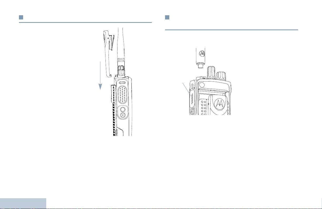
Montaggio della clip per cintura
Montaggio del cappuccio del connettore
universale (cappuccio parapolvere)
Allineare le scanalature della
Il connettore universale, situato sullo stesso lato dell’antenna, viene
clip a quelle sulla batteria,
utilizzato per collegare gli accessori MOTOTRBO alla radio.
quindi premere finché non
Inserire l’estremità del
scatta in posizione.
cappuccio dotata di un gancio
negli slot sopra il connettore
Per rimuovere la clip, con
universale. Premere il
l’ausilio di una chiave spingere
cappuccio per alloggiare
la linguetta della clip per
correttamente la linguetta
cintura in direzione opposta
inferiore nel connettore RF.
rispetto alla batteria, quindi far
Ruotare la vite ad alette in
scivolare la clip verso l’alto fino
senso orario per fissare il
a staccarla dalla radio.
cappuccio del connettore alla
radio.
Per rimuoverlo, premere il
cappuccio del connettore universale e ruotare la vite ad alette in
senso antiorario.
Riposizionare il cappuccio parapolvere quando il connettore
universale non è utilizzato.
Predisposizione della radio
4
Italiano
Connettore
universale
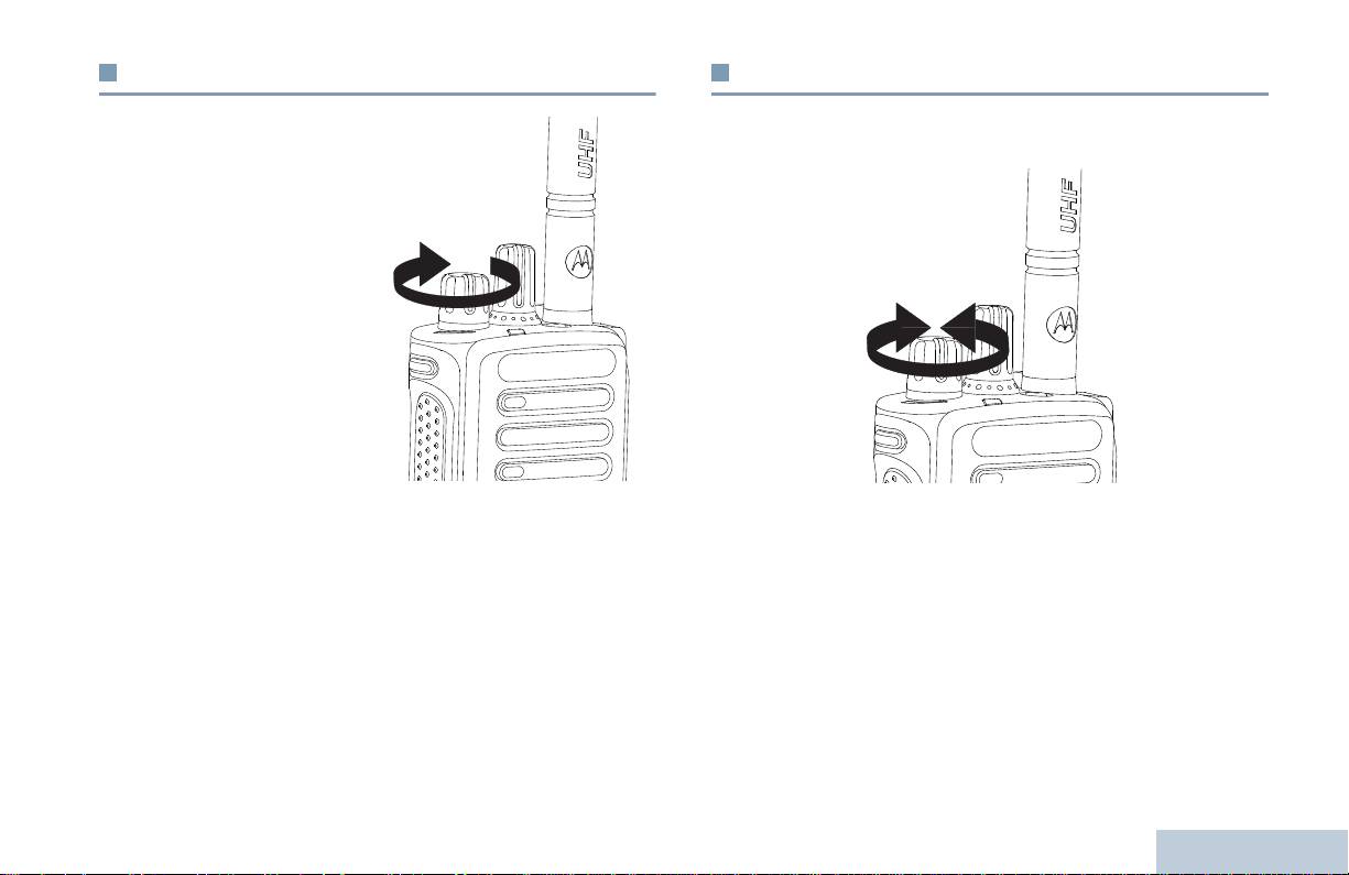
Accensione della radio
Regolazione del volume
Predisposizione della radio
Ruotare la manopola di
Per aumentare il volume, ruotare la manopola di accensione-
accensione-spegnimento/
spegnimento/comando del volume in senso orario.
comando volume in senso
orario finché non si avverte un
“clic”. Il LED si accende con
luce verde fissa.
Viene emesso un breve
segnale acustico, per
segnalare l’esito positivo
dell’autodiagnostica
all’accensione.
NOTA: Se la funzione Toni/
Avvisi è disabilitata, la
radio non emette un
segnale acustico
(vedere Attivazione e disattivazione dei toni e degli
Per abbassare il volume, ruotare la manopola in senso antiorario.
avvisi a pagina 37).
Se la radio non si accende, controllare che la batteria sia carica e
NOTA: è possibile programmare la funzione di offset del volume
che sia inserita correttamente. Se la radio continua a non
minimo, che impedisce di abbassare il volume al di sotto
accendersi, rivolgersi al proprio distributore.
del valore minimo programmato. Per ulteriori informazioni,
rivolgersi al proprio distributore o all’amministratore di
Per spegnere la radio, ruotare la manopola in senso antiorario
sistema.
finché non si avverte un "clic".
5
Italiano
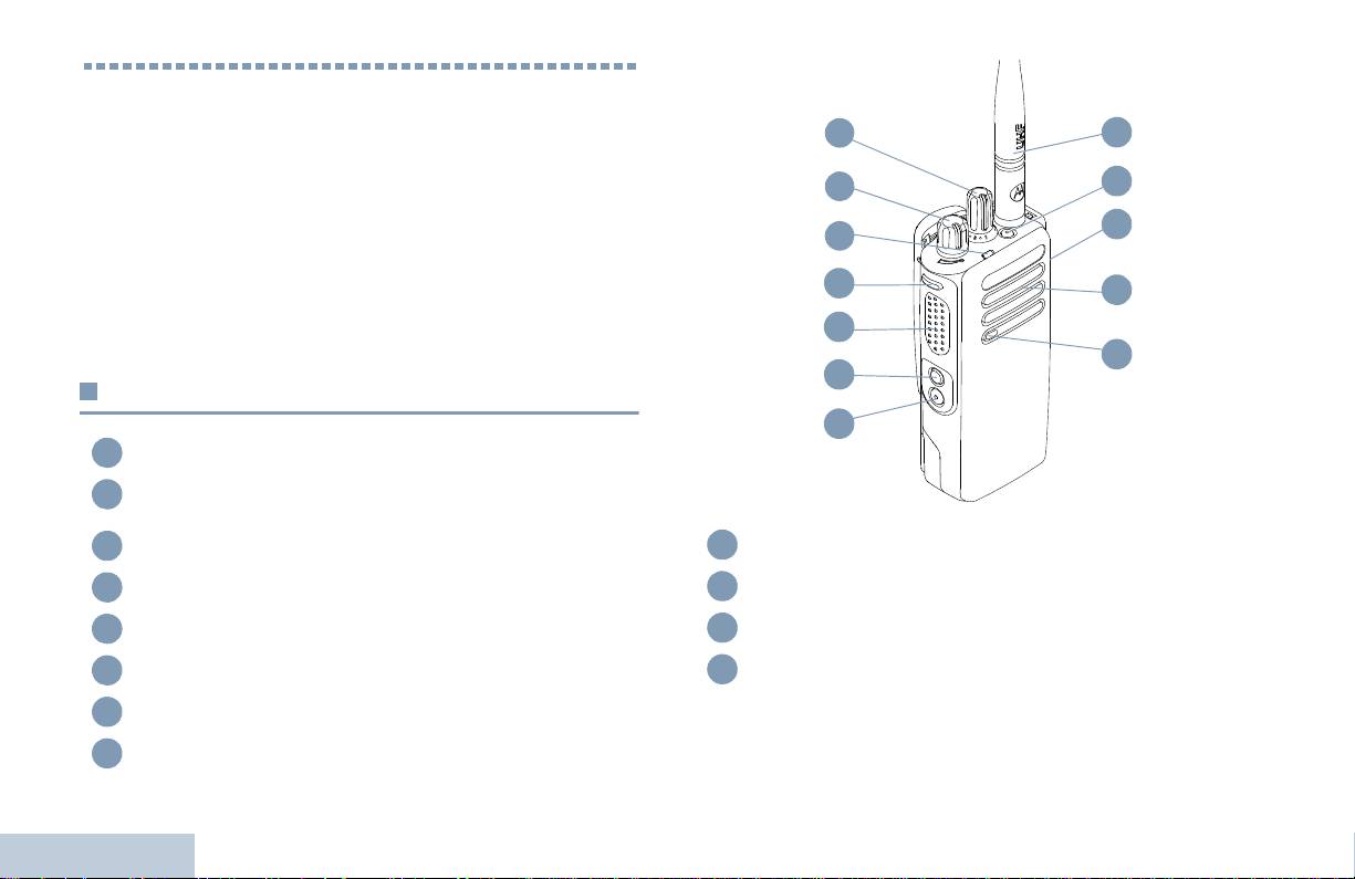
Comandi della radio
Prima di utilizzare la radio, leggere i seguenti argomenti:
Funzioni di comando . . . . . . . . . . . . . . . . . . . . . . . . . . . . pagina 6
Pulsanti programmabili. . . . . . . . . . . . . . . . . . . . . . . . . . . pagina 7
Pulsante PTT (premere per parlare) . . . . . . . . . . . . . . . . pagina 8
Commutazione tra le modalità convenzionali
analogica e digitale. . . . . . . . . . . . . . . . . . . . . . . . . . . . pagina 9
Connessione IP Site. . . . . . . . . . . . . . . . . . . . . . . . . . . . pagina 10
Capacity Plus . . . . . . . . . . . . . . . . . . . . . . . . . . . . . . . . . pagina 10
Linked Capacity Plus . . . . . . . . . . . . . . . . . . . . . . . . . . . pagina 11
Funzioni di comando
Manopola di selezione canale
Manopola di accensione-spegnimento (On-Off)/comando
volume
Indicatore LED
Pulsante laterale 1*
Pulsante premere per parlare (PTT)
Pulsante laterale 2*
Comandi della radio
Pulsante laterale 3*
Microfono
6
Italiano
1
2
3
4
5
6
7
8
Altoparlante
Connettore accessori universale
Pulsante di emergenza*
Antenna
* Questi pulsanti possono essere programmati.
1
12
2
11
10
3
4
9
5
8
6
7
9
10
11
12

Annuncio vocale per canale – per riprodurre gli annunci vocali
Pulsanti programmabili
della zona o del canale per il canale attualmente inserito. Questa
funzione non è disponibile se la funzione Annuncio vocale è
Comandi della radio
Il distributore può programmare i pulsanti programmabili come tasti
disabilitata.
di scelta rapida per accedere direttamente alle funzioni della
radio, oppure per selezionare canali o gruppi predefiniti a
Emergenza – per inviare o annullare un allarme o una chiamata di
seconda della durata della pressione sul pulsante:
emergenza, a seconda della programmazione.
• Pressione breve – premere e rilasciare rapidamente il pulsante.
Audio intelligente attivo/disattivo – attiva o disattiva la funzione
Audio intelligente.
• Pressione lunga – premere e tenere premuto il pulsante per un
periodo di tempo programmato.
‡
Roaming manuale sito
*
– per avviare la ricerca manuale del
sito.
• Tener premuto – tenere premuto il pulsante.
AGC mic attivo/disattivo – attiva o disattiva il controllo automatico
NOTA: la durata programmata della pressione su un pulsante è
del guadagno (AGC) del microfono interno. Non è disponibile
disponibile per tutte le funzioni o le impostazioni
durante una sessione Bluetooth.
assegnabili della radio e delle utility. Per ulteriori
informazioni sulla durata programmata del pulsante
Monitor – per controllare la presenza di traffico sul canale
Emergenza, vedere Emergenza a pagina 27.
selezionato.
‡
Eliminazione canale di disturbo*
– rimuove temporaneamente
Funzioni assegnabili
dalla lista di scansione un canale non gradito, ad eccezione del
canale selezionato. Per canale selezionato si intende la
TM
Commutazione audio Bluetooth
– consente di alternare
combinazione zona/canale selezionata dall’utente all’avvio della
l’instradamento dell’audio tra l‘altoparlante interno della radio e
scansione.
l'accessorio Bluetooth esterno.
Accesso rapido –
per iniziare direttamente una chiamata
Connessione Bluetooth – avvia un'operazione di individuazione e
privata, telefonica o di gruppo, un avviso di chiamata o un
connessione al dispositivo Bluetooth.
messaggio predefinito.
Funzione scheda opzioni – consente di abilitare e disabilitare la
Disconnessione Bluetooth – interrompe tutte le connessioni
funzionalità offerta dalla scheda opzioni sui canali in cui è
Bluetooth esistenti tra radio e dispositivi Bluetooth.
configurata.
Trasferimento di chiamata – consente di attivare e disattivare la
funzione di trasferimento di chiamata.
7
Italiano
* Non disponibile in Capacity Plus
‡
Non disponibile in Linked Capacity Plus
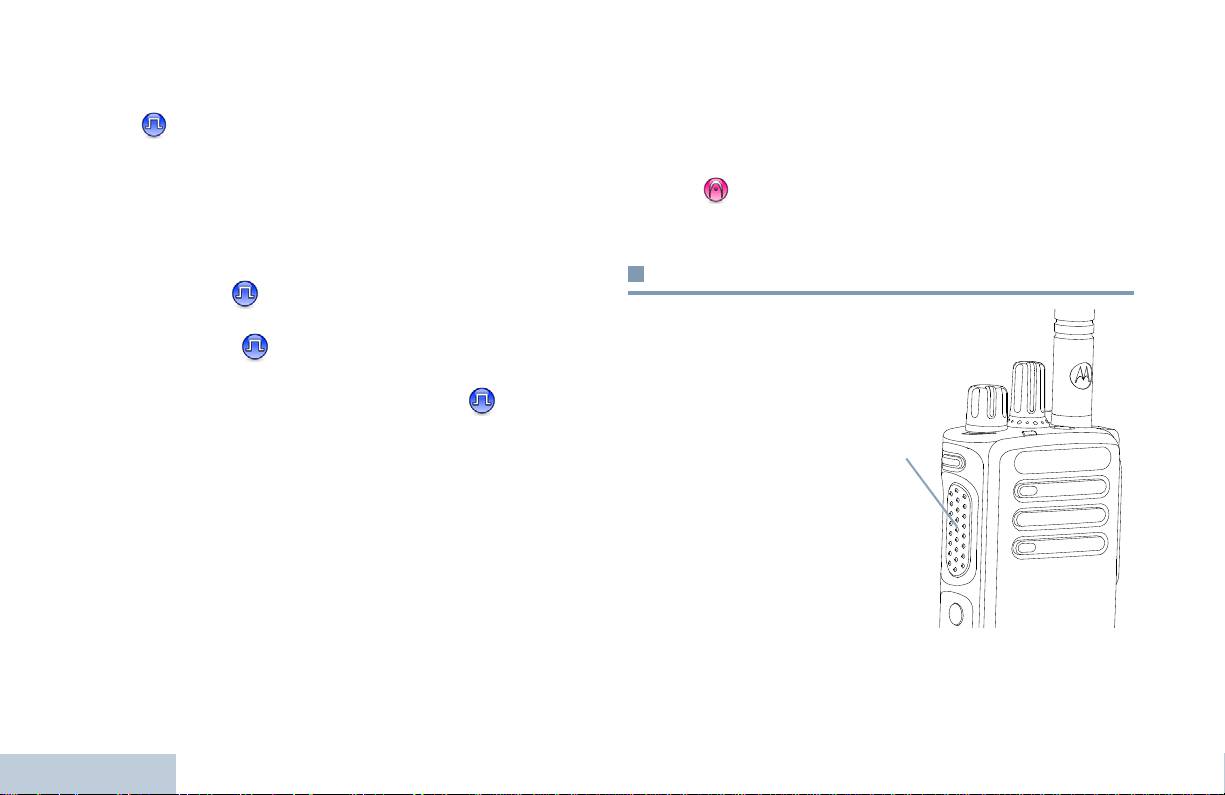
‡
Monitor permanente*
– per controllare la presenza di traffico sul
Impostazioni assegnabili e utilità
canale selezionato fino alla disattivazione della funzione.
Tutti i toni/avvisi – per attivare e disattivare tutti i toni.
Privacy –
consente di abilitare o disabilitare la funzione
Livello di potenza – per selezionare alternativamente il livello di
Privacy.
trasmissione alto o basso.
‡
Ripetitore/Comunicazione diretta*
– per selezionare
Squelch –
per selezionare alternativamente il livello di
alternativamente la comunicazione con ripetitore oppure diretta da
squelch normale o stretto.
una radio all’altra.
‡
Scansione*
– per abilitare o disabilitare la scansione.
Pulsante PTT (premere per parlare)
Blocco sito on/off
* – consente di attivare e disattivare il
roaming manuale del sito.
Il pulsante PTT sul lato del
Controllo telemetria –
per controllare il pin di output in una
microfono ha due funzioni
radio vicina o distante.
fondamentali:
Disattivazione remota interruzione trasmissione –
• Durante una chiamata, il
interrompe una chiamata in corso che può essere sospesa per
PTT consente alla radio
liberare il canale.
di trasmettere alle altre
radio chiamate.
Annuncio vocale on/off – attiva o disattiva la funzione Annuncio
vocale.
Per parlare, premere e
Trasmissione attivata dalla voce (VOX) – consente di attivare e
tener premuto il pulsante
disattivare la funzione VOX.
PTT; rilasciarlo per
ascoltare.
Zona – per selezionare la zona voluta in una lista.
Carica batteria – segnala il livello di carica della batteria mediante
Il microfono viene
un indicatore LED.
attivato premendo il
Comandi della radio
pulsante PTT.
8
Italiano
* Non disponibile in Capacity Plus
‡
Non disponibile in Linked Capacity Plus
Pulsante
PTT
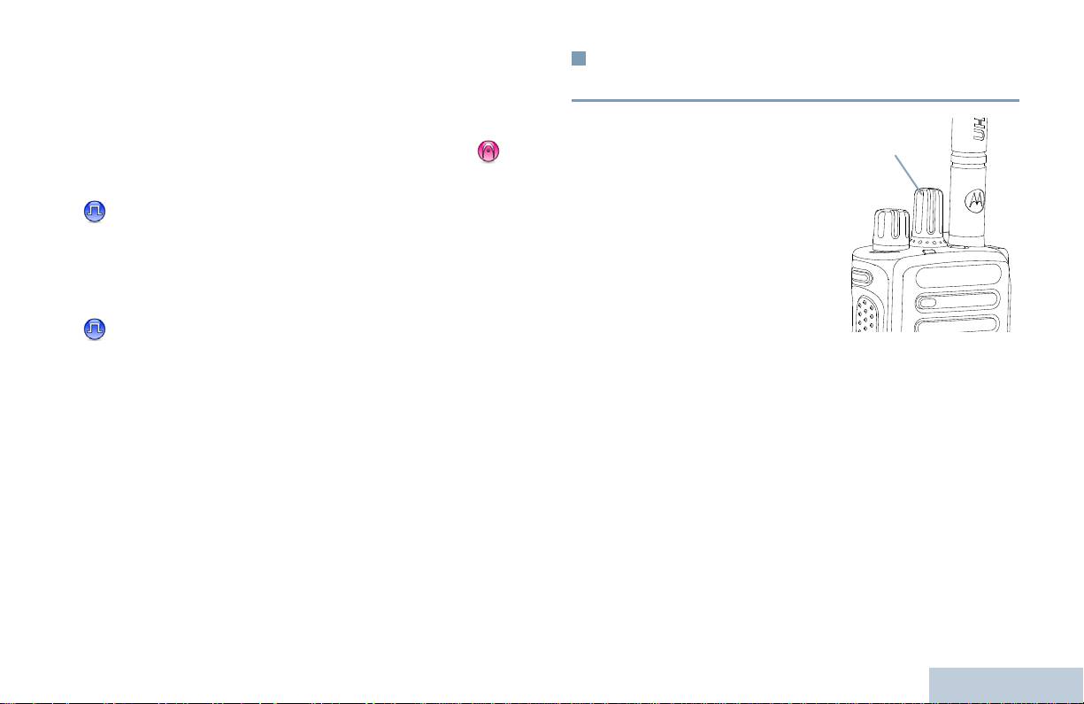
• Quando la radio è inattiva, il pulsante PTT viene utilizzato per
Commutazione tra le modalità
inviare una nuova chiamata (vedere Invio di una chiamata
convenzionali analogica e digitale
radio a pagina 18).
Comandi della radio
A seconda di come è stata programmata la radio, se è stato
È possibile configurare ogni
abilitato il tono di permesso di parlare o il sidetone del PTT ,
canale della radio come
attendere la fine del breve segnale acustico prima di parlare.
canale convenzionale
analogico o digitale. Utilizzare
il selettore di canale per
Durante una chiamata, se la funzione Indicazione canale
passare da un canale
libero è abilitata nella radio (programmata dal distributore),
analogico ad uno digitale e
verrà emesso un breve tono di avviso quando il pulsante PTT
viceversa.
viene rilasciato nella radio ricevente (la radio che riceve la
chiamata), per segnalare che il canale è libero per rispondere.
Alcune funzioni non sono
disponibili quando si passa
dalla modalità digitale a quella
Se la chiamata viene interrotta, verrà emesso un tono continuo
analogica.
(proibizione di parlare) che segnala di rilasciare il pulsante
PTT, ad esempio quando la radio riceve una chiamata di
Alcune funzioni sono disponibili in entrambe le modalità. Le lievi
emergenza.
differenze operative NON incidono comunque sulle prestazioni
della radio.
NOTA: la radio può passare alternativamente dalla modalità
digitale a quella analogica anche durante la scansione in
doppia modalità (vedere Scansione a pagina 24).
9
Italiano
Manopola di selezione
canale

È impossibile aggiungere o eliminare manualmente una voce dalla
Connessione IP Site
lista di roaming. Per ulteriori informazioni, rivolgersi al proprio
distributore o all’amministratore di sistema.
Questa funzione consente di estendere le comunicazioni
convenzionali oltre la portata di un singolo sito, collegandosi ai
diversi siti disponibili, che sono connessi tramite una rete IP
Capacity Plus
(Internet Protocol).
Quando la radio esce dal campo di copertura di un sito ed entra in
Capacity Plus è una configurazione multiaccesso a sito singolo del
quello di un altro, si connette al ripetitore del nuovo sito per inviare
sistema radio MOTOTRBO, in cui un pool di canali viene utilizzato
o ricevere chiamate e trasmissioni dati. A seconda delle
per supportare centinaia di utenti e un numero massimo di 254
impostazioni assegnate, la connessione viene effettuata
gruppi. Questa funzione consente alla radio di utilizzare in modo
automaticamente o manualmente.
efficiente il numero disponibile di canali programmati durante la
Se è stata impostata la ricerca automatica del sito, la radio esegue
modalità operativa Ripetitore.
la scansione di tutti i siti disponibili se rileva un segnale debole o
Le icone delle funzioni non supportate in Capacity Plus non
nessun segnale dal sito corrente. Quindi si connette al ripetitore
saranno disponibili nel menu. Se si accede a una funzione non
con il valore RSSI (Received Signal Strength Indicator o indicatore
supportata premendo un pulsante programmabile, verrà emesso un
intensità segnale ricevuto) maggiore.
tono di segnalazione negativo.
Nella ricerca manuale del sito, la radio ricerca il sito successivo
La radio dispone anche di funzioni supportate sia nel modo digitale
disponibile tra i membri della lista di roaming, anche se questo non
convenzionale che nelle modalità IP Site Connect, Capacity Plus e
è necessariamente quello con il segnale più forte, e si collega ad
Linked Capacity Plus. Le lievi differenze operative NON incidono
esso.
comunque sul funzionamento delle singole funzioni né sulle
prestazioni della radio.
NOTA: è possibile abilitare solo la funzione di scansione oppure
quella di roaming su ogni canale, ma non entrambe.
Per ulteriori informazioni su questa configurazione, rivolgersi al
proprio distributore o all'amministratore di sistema.
A una lista di roaming specifica possono essere aggiunti solo i
canali sui quali è stata abilitata questa funzione. Durante il roaming
automatico, la radio cerca tra i canali della lista di roaming quello
Comandi della radio
con il segnale più forte.
Una lista di roaming supporta fino a 16 canali, compreso il canale
selezionato.
10
Italiano

NOTA: è impossibile aggiungere o eliminare manualmente una
Linked Capacity Plus
voce dalla lista di roaming. Per ulteriori informazioni,
rivolgersi al proprio distributore o all’amministratore di
Comandi della radio
Linked Capacity Plus è una configurazione trunking, multisito e
sistema.
multicanale del sistema radio MOTOTRBO, che abbina le
configurazioni ottimali di Capacity Plus ed IP Site Connect.
In modo analogo a Capacity Plus, le icone delle funzioni non
Linked Capacity Plus consente di estendere le comunicazioni
supportate nel modo Linked Capacity Plus non sono disponibili nel
trunking oltre la portata di un singolo sito, collegandosi ai diversi siti
menu. Se si accede a una funzione non supportata nel modo
disponibili che sono connessi tramite una rete IP (Internet
Linked Capacity Plus tramite una pressione sul pulsante
Protocol). Offre inoltre una maggiore capacità utilizzando in modo
programmabile, viene emesso un tono di segnalazione negativo.
efficiente il numero complessivo di canali programmati supportati
Per ulteriori informazioni su questa configurazione, rivolgersi al
da ciascuno dei siti disponibili.
proprio distributore o all'amministratore di sistema.
Quando la radio esce dal campo di copertura di un sito ed entra in
quello di un altro, si connette al ripetitore del nuovo sito per inviare
o ricevere chiamate e trasmissioni dati. A seconda delle
impostazioni assegnate, la connessione viene effettuata
automaticamente o manualmente.
Se è stata impostata la ricerca automatica del sito, la radio esegue
la scansione di tutti i siti disponibili se rileva un segnale debole o
nessun segnale dal sito corrente. Quindi si connette al ripetitore
con il valore RSSI (Received Signal Strength Indicator o indicatore
intensità segnale ricevuto) maggiore.
Nella ricerca manuale del sito, la radio ricerca il sito successivo
disponibile tra i membri della lista di roaming, anche se questo non
è necessariamente quello con il segnale più forte, e si collega ad
esso.
È possibile aggiungere a una lista di roaming specifica qualsiasi
canale sul quale è stata abilitata la modalità Linked Capacity Plus.
Durante il roaming automatico, la radio esegue la ricerca tra questi
canali per individuare il sito migliore.
11
Italiano

Verde, doppio lampeggio – la radio sta ricevendo una chiamata o
Indicatori di stato
dati crittati con lo scrambling.
Giallo a luce fissa – monitoraggio in corso di un canale
La radio segnala il suo stato operativo mediante i seguenti
convenzionale. Quando si preme il pulsante Carica batteria, indica
indicatori:
anche un adeguato stato di carica della batteria.
Indicatore LED . . . . . . . . . . . . . . . . . . . . . . . . . . . . . . . . pagina 12
Giallo lampeggiante – indica che è in corso la scansione per
Toni audio. . . . . . . . . . . . . . . . . . . . . . . . . . . . . . . . . . . . pagina 13
rilevare il traffico sul canale o la ricezione di un avviso di chiamata,
Toni di segnalazione. . . . . . . . . . . . . . . . . . . . . . . . . . . . pagina 13
oppure che tutti i canali locali Linked Capacity Plus sono occupati.
Giallo, doppio lampeggio – indica che la radio non è più
Indicatore LED
connessa al ripetitore mentre è nella modalità operativa Capacity
Plus o Linked Capacity Plus, che tutti i canali Capacity Plus o
L’indicatore LED segnala lo stato
Linked Capacity Plus sono attualmente occupati, che il roaming
operativo della radio.
automatico è attivato oppure che è in corso la ricerca di un nuovo
Rosso lampeggiante – lo stato
sito. Indica inoltre che la radio non ha ancora risposto a un avviso di
di carica della batteria è basso, è
chiamata di gruppo, oppure che è bloccata.
in corso la ricezione di una
trasmissione di emergenza
NOTA: nella modalità operativa convenzionale, il
oppure l’autodiagnostica
lampeggiamento del LED verde segnala che la radio ha
all’accensione non ha avuto esito
rilevato la presenza di traffico. Vista la natura del
positivo.
protocollo digitale, la presenza di tale attività potrebbe
Verde a luce fissa – accensione
avere o non avere effetti sul canale programmato della
della radio o trasmissione in
radio.
corso. Indica anche che la
batteria è completamente carica
In Capacity Plus e Linked Capacity Plus, non ci sono
quando si preme il pulsante
segnalazioni con LED quando rileva attività via etere.
Carica batteria.
Indicatori di stato
Verde lampeggiante – ricezione
in corso di una chiamata o di dati
con funzione privacy disattivata,
oppure rilevamento di traffico.
12
Italiano
Indicatore LED
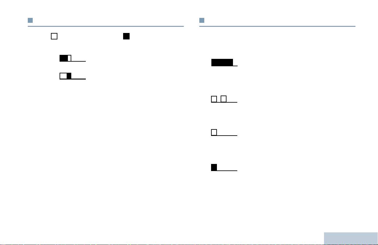
Toni di segnalazione
Toni audio
Indicatori di stato
I toni di avviso segnalano acusticamente lo stato operativo della
Tono alto Tono basso
radio oppure la risposta ai dati ricevuti.
Tono di segnalazione
Tono continuo Viene emesso un singolo tono, che
positivo
continua fino al termine della
trasmissione.
Tono di segnalazione
negativo
Tono periodico Viene emesso un tono intervallato, a
seconda della durata impostata. Il tono
inizia, finisce e viene ripetuto.
Tono ripetuto Viene emesso un singolo tono, che si
ripete finché non viene annullato
dall’utente.
Tono momentaneo
Un tono viene emesso una volta sola per
un breve periodo di tempo predefinito.
13
Italiano

Selezione di un canale
Ricezione e invio delle chiamate
Le trasmissioni vengono inviate e ricevute su un canale. A seconda
La radio portatile MOTOTRBO è pronta all’uso non appena l’utente
della configurazione della radio, ogni canale può essere stato
ha appreso la configurazione.
programmato in modo diverso per supportare gruppi di utenti
Questa guida alla navigazione permette all’utente di familiarizzare
diversi oppure può essere fornito con funzioni differenti. Dopo aver
le funzioni di chiamata fondamentali.
selezionato la zona desiderata. selezionare il canale su cui si
Selezione di una zona . . . . . . . . . . . . . . . . . . . . . . . . . . pagina 14
desidera trasmettere o ricevere.
Selezione di un canale. . . . . . . . . . . . . . . . . . . . . . . . . . pagina 14
Ricezione e risposta a una chiamata radio . . . . . . . . . . pagina 15
Invio di una chiamata radio . . . . . . . . . . . . . . . . . . . . . . pagina 18
Interruzione di una chiamata radio. . . . . . . . . . . . . . . . . pagina 21
Comunicazione diretta . . . . . . . . . . . . . . . . . . . . . . . . . . pagina 21
Funzioni di monitoraggio . . . . . . . . . . . . . . . . . . . . . . . . pagina 22
Selezione di una zona
La radio supporta fino a 32 canali e 2 zone, con un massimo di 16
canali per zona.
Procedura:
Procedura:
1 Premere il pulsante programmato Zona.
Ruotare il selettore canali per selezionare il canale con l’alias o
2 La radio emette un tono positivo, per indicare il passaggio dalla
l’ID di gruppo attivo.
Zona 1 alla Zona 2.
O
Ricezione e invio delle chiamate
La radio emette un tono negativo, per indicare il passaggio dalla
Zona 2 alla Zona 1.
14
Italiano
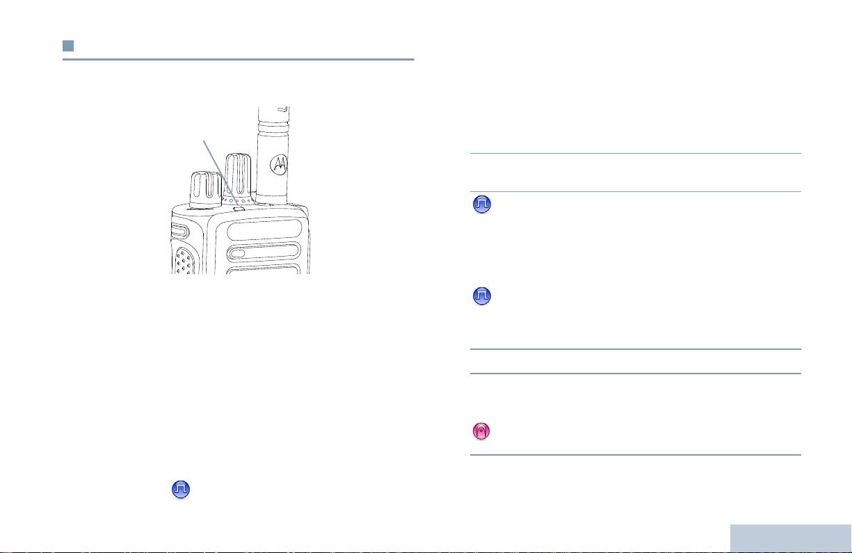
Ricezione e risposta a una chiamata radio
Ricezione e risposta a una chiamata di gruppo
Per ricevere una chiamata di un gruppo di utenti, la radio deve
Ricezione e invio delle chiamate
Una volta visualizzato il canale o l’ID di un utente o di un gruppo, è
essere configurata come appartenente a quel gruppo.
possibile ricevere e rispondere alle chiamate.
Procedura:
1 Il LED verde lampeggia. La radio si attiva e si ascolta la
chiamata in arrivo attraverso l'altoparlante della radio.
2 Per rispondere, tenere la radio in posizione verticale ad una
distanza di 2,5 - 5 cm dalla bocca.
3 Se la funzione Indicazione canale libero è abilitata, verrà
emesso un breve tono di avviso quando si rilascia il pulsante
PTT della radio trasmittente, per indicare che il canale è libero
per rispondere.
Premere il pulsante PTT per rispondere alla chiamata.
O
Il LED verde si illumina durante la trasmissione e lampeggia
Se la funzione Interruzione voce è abilitata, premere il
durante la ricezione.
pulsante PTT per interrompere la chiamata corrente ricevuta
NOTA: il LED verde si accende a luce fissa durante la
dalla radio trasmittente, liberando il canale per parlare/
trasmissione, mentre il doppio lampeggio indica la
rispondere.
ricezione con funzione privacy attivata.
4 Il LED verde si accende a luce fissa.
Per eseguire il descrambling delle chiamate crittate, la
5 Attendere che il tono di permesso di parlare (se abilitato)
radio ricevente deve avere la stessa chiave di Privacy O lo
finisca, quindi parlare chiaramente nel microfono.
stesso valore e lo stesso ID della chiave (programmati dal
O
distributore) di quella trasmittente (la radio che ha inviato
Attendere la cessazione del sidetone del PTT (se
la chiamata).
abilitato), quindi parlare chiaramente nel microfono.
Per ulteriori informazioni, vedere Privacy a
pagina 31.
15
Italiano
Indicatore LED

6 Rilasciare il pulsante PTT per ascoltare.
5 Attendere che il tono di permesso di parlare (se abilitato)
finisca, quindi parlare chiaramente nel microfono.
7 Se non viene rilevato traffico vocale per un periodo
predeterminato, la chiamata viene terminata.
6 Rilasciare il pulsante PTT per ascoltare.
Per inviare una chiamata di gruppo, vedere Invio di una chiamata
7 Se non viene rilevato traffico vocale per un periodo
di gruppo a pagina 18.
predeterminato, la chiamata viene terminata.
8 La radio emette un tono breve.
Ricezione e risposta a una chiamata privata
Per inviare una chiamata privata, vedere Invio di una chiamata
Per chiamata privata si intende una chiamata da una radio
privata a pagina 19.
individuale verso un’altra.
Procedura:
Alla ricezione di una chiamata privata:
1 Il LED verde lampeggia. La radio si attiva e si ascolta la
chiamata in arrivo attraverso l'altoparlante della radio.
2 Per rispondere, tenere la radio in posizione verticale ad una
distanza di 2,5 - 5 cm dalla bocca.
3 Se la funzione Indicazione canale libero è abilitata, verrà
emesso un breve tono di avviso quando si rilascia il pulsante
PTT della radio trasmittente, per indicare che il canale è libero
per rispondere.
O
Se la funzione Interruzione voce è abilitata, premere il pulsante
PTT per interrompere la chiamata corrente ricevuta dalla radio
trasmittente, liberando il canale per parlare/rispondere.
Ricezione e invio delle chiamate
4 Premere il pulsante PTT per rispondere alla chiamata. Il LED
verde si accende a luce fissa.
16
Italiano

Ricezione di una chiamata generale
Ricezione e risposta a una chiamata selettiva
Per chiamata generale si intende una chiamata inviata da una radio
Per chiamata selettiva si intende una chiamata tra due radio
Ricezione e invio delle chiamate
a tutte le radio sintonizzate sullo stesso canale. Si rivela utile per
individuali. In un sistema analogico è una chiamata privata.
trasmettere comunicazioni importanti che richiedono l’immediata
Procedura:
attenzione dell'utente.
Quando la radio riceve una chiamata selettiva:
Procedura:
1 Il LED verde lampeggia.
Alla ricezione di una chiamata generale:
2 Tenere la radio in posizione verticale ad una distanza di
1 Viene emesso un segnale acustico e il LED verde lampeggia.
2,5 - 5 cm dalla bocca. La radio si attiva e si ascolta la chiamata
La radio si attiva e si ascolta la chiamata in arrivo attraverso
in arrivo attraverso l'altoparlante della radio.
l'altoparlante della radio.
3 Se la funzione Indicazione canale libero è abilitata, verrà
2 Se non viene rilevato traffico vocale per un periodo di tempo
emesso un breve tono di avviso quando si rilascia il pulsante
predeterminato, la chiamata generale viene interrotta. Prima di
PTT della radio trasmittente, per indicare che il canale è libero
essere conclusa, una chiamata generale non attende lo
per rispondere.
scadere del periodo di tempo predeterminato.
Se la funzione Indicazione canale libero è abilitata, verrà
4 Premere il pulsante PTT per rispondere alla chiamata. Il LED
emesso un breve tono di avviso quando si rilascia il pulsante
verde si accende a luce fissa.
PTT della radio trasmittente, per indicare che il canale è libero
5 Attendere che il tono di permesso di parlare (se abilitato)
per rispondere.
finisca, quindi parlare chiaramente nel microfono.
Non si può rispondere a una chiamata generale.
6 Rilasciare il pulsante PTT per ascoltare.
NOTA: se si cambia canale durante la ricezione, la chiamata
7 Se non viene rilevato traffico vocale per un periodo
generale viene terminata.
predeterminato, la chiamata viene terminata.
L’utente non può utilizzare le funzioni assegnate ai
8 La radio emette un tono breve.
pulsanti programmabili, né effettuare alcuna modifica fino
al termine della chiamata generale.
Per inviare una chiamata privata, vedere Invio di una chiamata
selettiva a pagina 19.
17
Italiano
Procedura:
Invio di una chiamata radio
1 Selezionare il canale con l’alias o l’ID di gruppo attivo. Vedere
Dopo aver selezionato il canale, è possibile selezionare un alias o
Selezione di un canale a pagina 14.
ID subscriber o di gruppo:
O
Premere il pulsante programmato Accesso rapido.
• la manopola di selezione canale
• un pulsante programmato come pulsante di
2 Tenere la radio in posizione verticale ad una distanza di
accesso rapido
2,5 - 5 cm dalla bocca.
3 Premere il pulsante PTT per effettuare la chiamata. Il LED
NOTA: per inviare una trasmissione criptata, la funzione Privacy
deve essere abilitata sul canale. Solo le radio riceventi che
verde si accende a luce fissa.
hanno la stessa chiave di Privacy OPPURE lo stesso
4 Attendere che il tono di permesso di parlare (se abilitato)
valore e ID della chiave della radio trasmittente possono
finisca, quindi parlare chiaramente nel microfono.
decriptare la trasmissione.
O
Attendere la cessazione del sidetone del PTT (se
Per ulteriori informazioni, vedere Privacy a
abilitato), quindi parlare chiaramente nel microfono.
pagina 31.
5 Rilasciare il pulsante PTT per ascoltare. Quando la radio
La funzione Accesso rapido consente di effettuare con
chiamata risponde, il LED verde lampeggia.
facilità una chiamata di gruppo o privata a un ID
6 Se la funzione Indicazione canale libero è abilitata, verrà
predefinito. È possibile assegnare questa funzione alla
pressione, breve o lunga, di un pulsante programmabile.
emesso un breve tono di avviso quando l’utente della radio
SOLO un ID può essere assegnato a un pulsante di
ricevente rilascia il pulsante PTT, per indicare che il canale è
accesso rapido. E’ possibile programmare la funzione
libero per rispondere.
Accesso rapido su più pulsanti.
Premere il pulsante PTT per rispondere.
O
Invio di una chiamata voce con il selettore di canale
Se non viene rilevato traffico vocale per un periodo
predeterminato, la chiamata viene terminata.
Ricezione e invio delle chiamate
Invio di una chiamata di gruppo
Per inviare una chiamata a un gruppo di utenti, la radio deve essere
configurata come appartenente a quel gruppo.
18
Italiano

4 Attendere che il tono di permesso di parlare (se abilitato)
Invio di una chiamata privata
finisca, quindi parlare chiaramente nel microfono.
Mentre è possibile ricevere e/o rispondere a una chiamata privata
Ricezione e invio delle chiamate
5 Rilasciare il pulsante PTT per ascoltare. Quando la radio
inviata da una radio individuale non autorizzata, la funzione
chiamata risponde, il LED verde lampeggia.
Chiamata privata deve essere programmata nella radio per poter
inviare questo tipo di chiamata.
6 Se la funzione Indicazione canale libero è abilitata, verrà
Le chiamate private sono di due tipi. Nel primo tipo, la disponibilità
emesso un breve tono di avviso quando l’utente della radio
della radio viene controllata prima di instradare la chiamata, mentre
ricevente rilascia il pulsante PTT, per indicare che il canale è
nel secondo la chiamata viene inviata subito.
libero per rispondere. Premere il pulsante PTT per rispondere.
O
Il distributore di fiducia può programmare solo uno di questi due tipi
Se non viene rilevato traffico vocale per un periodo
di chiamata.
predeterminato, la chiamata viene terminata.
Se si cerca di inviare una Chiamata privata utilizzando il pulsante di
7 La radio emette un tono breve.
accesso rapido o il selettore canali, ma questa funzione non è
abilitata, viene emesso un tono di segnalazione negativo.
Invio di una chiamata selettiva
Per contattare una radio individuale, utilizzare le funzioni
Messaggio predefinito o Avviso di chiamata. Per ulteriori
In modo analogo alla chiamata privata, è possibile ricevere e/o
informazioni, vedere Messaggi di testo a pagina 30 o Avvisi di
rispondere a una chiamata selettiva inviata da una radio individuale
chiamata a pagina 26.
autorizzata, a condizione che la funzione Chiamata selettiva sia
programmata nella radio per l'invio di questo tipo di chiamata.
Procedura:
Procedura:
1 Selezionare il canale con l’alias o l’ID di gruppo attivo. Vedere
Selezione di un canale a pagina 14.
1 Selezionare il canale con l’alias o l’ID di gruppo attivo. Vedere
O
Selezione di un canale a pagina 14.
Premere il pulsante programmato Accesso rapido.
2 Tenere la radio in posizione verticale ad una distanza di
2 Tenere la radio in posizione verticale ad una distanza di
2,5 - 5 cm dalla bocca.
2,5 - 5 cm dalla bocca.
3 Premere il pulsante PTT per effettuare la chiamata. Il LED
3 Premere il pulsante PTT per effettuare la chiamata. Il LED
verde si accende a luce fissa.
verde si accende a luce fissa.
19
Italiano

4 Attendere che il tono di permesso di parlare (se abilitato)
4 Attendere che il tono di permesso di parlare (se abilitato)
finisca, quindi parlare chiaramente nel microfono.
finisca, quindi parlare chiaramente nel microfono.
O
5 Rilasciare il pulsante PTT per ascoltare. Quando la radio
Attendere la cessazione del sidetone del PTT (se
chiamata risponde, il LED verde lampeggia.
abilitato), quindi parlare chiaramente nel microfono.
6 Se la funzione Indicazione canale libero è abilitata, verrà
emesso un breve tono di avviso quando l’utente della radio
Gli utenti del canale non possono rispondere a una chiamata
ricevente rilascia il pulsante PTT, per indicare che il canale è
inviata a tutte le radio.
libero per rispondere. Premere il pulsante PTT per rispondere.
O
Se non viene rilevato traffico vocale per un periodo
predeterminato, la chiamata viene terminata.
7 La radio emette un tono breve.
Invio di una chiamata generale
Questa funzione consente di inviare una trasmissione a tutti gli
utenti sintonizzati sul canale. Questa funzione è disponibile solo se
programmata nella radio.
Procedura:
1 Selezionare il canale con l’alias o l’ID di gruppo attivo. Vedere
Selezione di un canale a pagina 14.
2 Tenere la radio in posizione verticale ad una distanza di
2,5 - 5 cm dalla bocca.
3 Premere il pulsante PTT per effettuare la chiamata. Il LED
Ricezione e invio delle chiamate
verde si accende a luce fissa.
20
Italiano

Interruzione di una chiamata radio
Comunicazione diretta
Ricezione e invio delle chiamate
Consente di interrompere una chiamata di gruppo o privata in corso
La radio può continuare a comunicare anche quando il ripetitore
per liberare il canale per la trasmissione. Ad esempio, nel caso il
non è operativo, oppure se la radio è fuori dal campo di copertura
microfono della radio sia rimasto bloccato poiché il pulsante PTT è
del ripetitore, ma all'interno di quello di altre radio. Questa modalità
stato premuto inavvertitamente dall’utente.
operativa è detta “comunicazione diretta”.
Questa funzione è disponibile solo se programmata nella radio.
NOTA: questa funzione non è disponibile in Capacity Plus e
Linked Capacity Plus.
Procedura:
Quando la radio è operativa sul canale desiderato:
Procedura:
1 Premere il pulsante programmato con la funzione
1 Premere il pulsante preprogrammato con la funzione
Disattivazione remota interruzione trasmissione.
Ripetitore/Comunicazione diretta.
2 Attendere la ricezione dell’autorisposta.
2 La radio emette un tono positivo per indicare l’accesso alla
3 La radio emette un tono di segnalazione positivo, per indicare
modalità operativa di comunicazione diretta senza ripetitore.
che il canale è libero.
O
O
La radio emette un tono negativo per indicare l’accesso alla
La radio emette un tono di segnalazione negativo, per indicare
modalità operativa con ripetitore.
che è impossibile liberare il canale.
L’impostazione selezionata viene memorizzata nella radio anche
Se la radio sta trasmettendo una chiamata che può essere sospesa
dopo averla spenta.
tramite questa funzione, emette un tono di segnalazione negativo
fino al rilasco del pulsante PTT. Sul display della radio la cui
trasmissione è stata interrotta (se dotata di display) viene
visualizzato Chiamata interrotta.
21
Italiano

Funzioni di monitoraggio
Monitor permanente
La funzione Monitor permanente consente di controllare
ininterrottamente l’attività su un canale selezionato.
Monitoraggio di un canale
La funzione Monitor consente di verificare se un canale è libero
NOTA: questa funzione non è disponibile in Capacity Plus e
prima di trasmettere.
Linked Capacity Plus.
NOTA: questa funzione non è disponibile in Capacity Plus e
Procedura:
Linked Capacity Plus.
1 Premere il pulsante preprogrammato con la funzione Monitor
permanente.
Procedura:
2 La radio emette un segnale acustico e il LED giallo si illumina.
1 Premere e tener premuto il pulsante preprogrammato con la
funzione Monitor e ascoltare per rilevare attività sul canale.
3 Per uscire da questa modalità operativa, premere nuovamente
2 A seconda di come la radio è programmata, si sentirà attività o
il pulsante preprogrammato Monitor permanente.
silenzio totale sul canale.
4 La radio emette un segnale acustico e il LED si spegne.
3 Se si sente un “rumore bianco” (che segnala l’assenza di
traffico sul canale), premere il pulsante PTT per parlare e
rilasciarlo per ascoltare. Il LED giallo si illumina.
Ricezione e invio delle chiamate
22
Italiano

Liste di scansione
Funzioni avanzate
Funzioni avanzate
Le liste di scansione vengono create e assegnate a canali o gruppi
Questa guida alla navigazione consente di approfondire la
individuali. La radio esegue la scansione per rilevare la presenza di
conoscenza della funzioni avanzate disponibili nella radio:
traffico voce controllando sequenzialmente i canali o i gruppi
Liste di scansione. . . . . . . . . . . . . . . . . . . . . . . . . . . . . . pagina 23
assegnati alla lista di scansione selezionata.
Scansione. . . . . . . . . . . . . . . . . . . . . . . . . . . . . . . . . . . . pagina 24
La radio può contenere fino a 250 liste di scansione, con un
Impostazioni degli indicatori di chiamata . . . . . . . . . . . . pagina 26
massimo di 16 membri per lista. È possibile immettere nella lista di
Avvisi di chiamata. . . . . . . . . . . . . . . . . . . . . . . . . . . . . . pagina 26
scansione un insieme di voci analogiche e digitali.
Emergenza. . . . . . . . . . . . . . . . . . . . . . . . . . . . . . . . . . . pagina 27
NOTA: questa funzione non è disponibile in Capacity Plus e
Messaggi di testo . . . . . . . . . . . . . . . . . . . . . . . . . . . . . . pagina 30
Linked Capacity Plus.
Privacy . . . . . . . . . . . . . . . . . . . . . . . . . . . . . . . . . . . . . . pagina 31
Controlli multisito . . . . . . . . . . . . . . . . . . . . . . . . . . . . . . pagina 32
Lavoratore solo. . . . . . . . . . . . . . . . . . . . . . . . . . . . . . . . pagina 33
Funzioni Blocco password . . . . . . . . . . . . . . . . . . . . . . . pagina 33
Bluetooth . . . . . . . . . . . . . . . . . . . . . . . . . . . . . . . . . . . . pagina 34
Utilità . . . . . . . . . . . . . . . . . . . . . . . . . . . . . . . . . . . . . . . pagina 36
23
Italiano

Scansione
Inizio e fine della scansione
Procedura:
Durante la scansione, la radio controlla sequenzialmente la lista di
1 Premere il pulsante programmato Scansione.
scansione preprogrammata per il canale corrente per rilevare la
O
presenza di traffico voce.
Con il selettore di canale selezionare un canale sul quale è
Il LED giallo lampeggia.
stata abilitata la scansione automatica.
Se, durante la scansione in modalità doppia, la radio è sintonizzata
2 All’attivazione della scansione, il LED giallo lampeggia e la
su un canale digitale e si sintonizza su un canale analogico, essa
radio emette un tono positivo.
passa automaticamente dalla modalità digitale a quella analogica
O
per la durata della chiamata. Lo stesso avviene nel caso opposto.
Alla disattivazione della scansione, il LED si spegne e la radio
Due sono i tipi di scansione:
emette un tono negativo.
• Scansione canale principale (manuale): la radio esegue la
scansione di tutti i canali e gruppi della lista di scansione.
Risposta a una trasmissione durante la scansione
Quando entra nella modalità di scansione, la radio, a seconda
Durante la scansione, la radio si sintonizza sul canale o gruppo sul
dell’impostazione, inizia automaticamente la scansione
quale ha rilevato la presenza di attività e resta sintonizzata su di
dall’ultimo canale o gruppo “attivo” controllato, oppure dal canale
esso per un periodo di tempo preprogrammato, detto tempo di
dal quale era originalmente iniziata.
coda.
• Scansione automatica: la scansione viene avviata
Procedura:
automaticamente se la funzione di scansione automatica è stata
1 Tenere la radio in posizione verticale ad una distanza di
abilitata per il canale o gruppo selezionato.
2,5 - 5 cm dalla bocca.
NOTA: questa funzione non è disponibile in Capacity Plus e
Se la funzione Indicazione canale libero è abilitata, verrà
Linked Capacity Plus.
emesso un breve tono di avviso quando si rilascia il pulsante
PTT della radio trasmittente, per indicare che il canale è libero
Funzioni avanzate
per rispondere.
2 Premere the PTT button during hang time. Il LED verde si
accende a luce fissa.
24
Italiano

3 Attendere che il tono di permesso di parlare (se abilitato)
Ripristino del canale di disturbo
finisca, quindi parlare chiaramente nel microfono.
Procedura:
O
Funzioni avanzate
Per ripristinare il canale di disturbo eliminato, eseguire una delle
Attendere la cessazione del sidetone del PTT (se
seguenti operazioni:
abilitato), quindi parlare chiaramente nel microfono.
• spegnere e riaccendere la radio, O
4 Rilasciare il pulsante PTT per ascoltare.
• arrestare e riavviare la scansione con il pulsante programmato
5 Se non si risponde durante il tempo di coda, la radio riprende la
Scansione, O
scansione dei canale o gruppi.
• cambiare canale con il selettore di canale.
Eliminazione del canale di disturbo
Scansione selettiva
È possibile rimuovere temporaneamente dalla lista di scansione un
canale che genera in continuazione chiamate o disturbi non graditi
(canale di “disturbo”).
La scansione selettiva consente di ottenere una copertura più
estesa nelle aree in cui sono operative più stazioni base che
Non è però possibile eliminare il canale designato come canale
trasmettono le stesse informazioni su canali analogici diversi.
selezionato.
La radio esegue la scansione dei canali analogici delle diverse
Procedura:
stazioni base ed effettua un processo di selezione selettiva per
1 Quando la radio si sintonizza su un canale non gradito o di
selezionare il segnale più forte. Una volta rilevato il segnale, la
disturbo, premere il pulsante preprogrammato con la funzione
radio viene abilitata alla ricezione trasmissioni da quella stazione
Eliminazione canale di disturbo fino alla ricezione di un
base.
segnale acustico.
Il LED giallo lampeggia durante la scansione selettiva.
2 Rilasciare il pulsante e il canale di disturbo viene rimosso.
Per rispondere a una trasmissione durante la scansione selettiva,
eseguire le stesse operazioni riportate in Risposta a una
trasmissione durante la scansione a pagina 24.
25
Italiano

Impostazioni degli indicatori di chiamata
Invio di un avviso di chiamata con il pulsante
accesso rapido
È possibile attivare e disattivare la suoneria che segnala la
Procedura:
ricezione di una chiamata privata (vedere Attivazione e
1 Premere il pulsante programmato come pulsante di accesso
disattivazione dei toni e degli avvisi a pagina 37).
rapido per inviare un avviso di chiamata all’ID predefinito.
Volume del tono per gli allarmi progressivi
2 Durante l'invio dell’avviso di chiamata, il LED verde si illumina.
Il distributore può programmare la radio in modo che emetta un
3 Se la radio ha ricevuto l’autorisposta all’avviso di chiamata,
segnale acustico continuo per avvisare l’utente dell’arrivo di una
emette due toni.
chiamata a cui non ha dato risposta. Questo avviso consiste in un
O
tono di allarme il cui volume aumenta automaticamente nel tempo.
Se la radio non ha ricevuto l’autorisposta all’avviso di chiamata,
Questa funzione è detta Allarme progressivo.
emette un tono basso.
Avvisi di chiamata
L’invio di avvisi di chiamata consente di avvisare un utente radio
specifico di richiamare non appena è disponibile. Si accede a
questa funzione per mezzo del pulsante programmato come
pulsante di accesso rapido.
Ricezione e risposta a un avviso di chiamata
Procedura:
Alla ricezione di un avviso di chiamata:
1 La radio emette un tono ripetitivo e il LED giallo lampeggia.
2 Premere il pulsante PTT entro quattro (4) secondi dalla
Funzioni avanzate
ricezione di un paging di avviso di chiamata per rispondere alla
chiamata privata.
26
Italiano

Inoltre, ogni allarme può essere:
Emergenza
• Regolare – la radio trasmette una segnalazione d’allarme e
Funzioni avanzate
L’allarme di emergenza viene inviato per segnalare una situazione
attiva gli indicatori audio e/o visivi.
critica. È possibile iniziare una trasmissione di emergenza in
• Silenzioso – la radio trasmette una segnalazione d’allarme
qualsiasi momento e in qualsiasi stato operativo la radio si trovi,
senza alcuna indicazione audio o visiva. La radio riceve le
anche in presenza di traffico sul canale attualmente utilizzato.
chiamate senza emettere alcun segnale acustico attraverso
Il distributore può impostare la durata della pressione di un pulsante
l’altoparlante fino a quando non si preme il pulsante PTT per
programmato come pulsante di emergenza, fatta eccezione per la
inziare la chiamata.
pressione lunga che è simile per tutti i pulsanti:
• Silenzioso con voce – la radio trasmette una segnalazione di
• Pressione breve – tra 0,05 e 0,75 secondi
allarme senza alcuna indicazione audio o visiva, ma permette di
udire le chiamate in arrivo attraverso l’altoparlante.
• Pressione lunga – tra 1,00 e 3,75 secondi
È possibile assegnare al pulsante preprogrammato o all'interruttore
Il pulsante Emergenza viene assegnato tramite la funzione
a pedale di emergenza solo uno degli allarmi sopradescritti.
Emergenza On/ Off. Per conoscere in che modo è stato
programmato il pulsante Emergenza, rivolgersi al distributore.
Invio di un allarme di emergenza
Se al pulsante Emergenza è stata assegnata una pressione breve
Questa funzione consente di inviare un allarme di emergenza,
per attivare la modalità di emergenza, la pressione lunga sullo
ossia un segnale non vocale, che attiva un indicatore di avviso in un
stesso pulsante è assegnata all’uscita dalla modalità Emergenza.
gruppo di radio.
Se al pulsante Emergenza è stata assegnata una pressione lunga
Procedura:
per attivare la modalità di emergenza, la pressione breve sullo
stesso pulsante è assegnata all’uscita dalla modalità Emergenza.
1 Premere il pulsante programmato Emergenza On.
2 Il LED verde si illumina.
La radio supporta tre allarmi di emergenza:
3 Quando la radio riceve l’autorisposta all’allarme di emergenza,
• Allarme emergenza
emette il tono di emergenza e il LED verde lampeggia
• Allarme di emergenza con chiamata
O
Se la radio non riceve l’autorisposta all’allarme di emergenza
• Emergenza con successiva trasmissione voce
dopo aver effettuato il numero massimo di tentativi, emette un
tono basso.
27
Italiano

4 La radio esce dalla modalità di emergenza.
7 Rilasciare il pulsante PTT per ascoltare.
8 Quando il canale è libero per rispondere, viene emesso un
Se la funzione Silenzioso è abilitata, la radio non emette né
breve tono di allarme ( se la funzione Indicazione canale
visualizza indicazioni audio o visive durante la modalità di
libero è attivata). Premere il pulsante PTT per rispondere.
emergenza.
O
Al termine della chiamata, premere il pulsante Emergenza off
Invio di un allarme di emergenza con chiamata
per uscire dalla modalità operativa emergenza.
Questa funzione consente di inviare un allarme di emergenza ad un
gruppo di radio. Alla ricezione dell’autorisposta da parte di una
Se la funzione Silenzioso è attivata, la radio non emette né
radio del gruppo, il gruppo di radio può comunicare sul canale di
visualizza indicazioni audio o visive durante la modalità di
emergenza programmato.
emergenza, né è possibile udire le chiamate voce inviate dalla radio
ricevente attraverso l’altoparlante della radio, finché non si preme il
Procedura:
pulsante PTT per instradare la chiamata.
1 Premere il pulsante programmato Emergenza On.
Se la funzione Silenzioso con voce è attivata, la radio non
2 Il LED verde si illumina.
visualizza né emette indicazioni audio o visive durante la modalità
di emergenza, ma è possibile udire le chiamate voce in entrata
3 Quando la radio riceve l’autorisposta all’allarme di emergenza,
attraverso l’altoparlante. Gli indicatori vengono attivati solo quando
emette il tono di emergenza e il LED verde lampeggia.
si preme il pulsante PTT per instradare la chiamata o per
rispondere.
4 Tenere la radio in posizione verticale ad una distanza di
2,5 - 5 cm dalla bocca.
Invio di un allarme di emergenza con successiva
5 Premere il pulsante PTT per effettuare la chiamata. Il LED
trasmissione voce
verde si illumina.
Questa funzione consente di inviare un allarme di emergenza ad un
6 Attendere la cessazione del tono di permesso di parlare (se
gruppo di radio. Il microfono della radio viene attivato
abilitato), quindi parlare chiaramente nel microfono.
automaticamente, consentendo al gruppo di radio di comunicare
O
senza premere il pulsante PTT.
Funzioni avanzate
Attendere la cessazione del sidetone del PTT (se
Questo stato di attivazione del microfono è detto anche
abilitato), quindi parlare chiaramente nel microfono.
“microfono hot".
28
Italiano

Se il modo Ciclo di emergenza è attivato nella radio, i periodi di
allo scadere della durata del modo microfono in uso, se il Modo
microfono hot e di ricezione vengono ripetuti per il tempo
ciclo di emergenza è disattivato.
programmato.
Funzioni avanzate
5 Per trasmettere nuovamente, premere il pulsante PTT.
NOTA: nel Modo ciclo di emergenza, le chiamate ricevute
O
vengono instradate attraverso l'altoparlante della radio.
Premere il pulsante Emergenza disattivata per uscire dalla
modalità operativa emergenza.
Se si preme il pulsante PTT durante il periodo di ricezione
programmato, viene emesso il segnale di divieto chiamata, che
Se la funzione Silenzioso è attivata, la radio non emette né
segnala che si deve rilasciare il pulsante PTT. La radio ignora la
visualizza indicazioni audio o visive durante la modalità di
pressione del pulsante PTT e resta nella modalità di emergenza.
emergenza, né è possibile udire le chiamate voce inviate dalla radio
NOTA: se si preme il pulsante PTT durante il periodo di
ricevente attraverso l’altoparlante, fino a quando il periodo
attivazione preprogrammato del microfono hot e si
programmato di attivazione del microfono hot non scade e non si
continua a premerlo dopo che è scaduto, la radio continua
preme il pulsante PTT.
a trasmettere fino al rilascio del pulsante.
Se la funzione Silenzioso con voce è attivata, la radio non
Procedura:
visualizza né emette indicazioni audio o visive durante la modalità
di emergenza, quando si invia la chiamata durante il periodo di
1 Premere il pulsante programmato Emergenza On.
attivazione del microfono hot, ma è possibile udire la chiamata voce
2 Il LED verde si illumina.
attraverso l’altoparlante quando la radio ricevente risponde dopo lo
scadere del periodo di attivazione programmato del microfono hot.
3 Quando viene emesso un tono, parlare chiaramente nel
Gli indicatori vengono attivati solo dopo aver premuto il pulsante
microfono. Se la funzione microfono “hot” è stata abilitata, la
PTT.
radio trasmette automaticamente, senza dover premere il PTT,
fino allo scadere del periodo preprogrammato.
NOTA: se la richiesta Allarme di emergenza non riesce, la radio
Durante la trasmissione, il LED verde si illumina.
non tenta nuovamente di inviarla, ma entra direttamente
nello stato microfono hot.
4 La radio arresta automaticamente la trasmissione:
allo scadere della durata del ciclo microfono in uso e ricezione
chiamate, se ilmModo Ciclo di emergenza è attivato.
O
29
Italiano
NOTA: spegnendo la radio si esce dalla modalità di emergenza.
Riavvio della modalità di emergenza
Dopo averla riaccesa, la radio non entra automaticamente
NOTA: questa funzione si riferisce solo alla radio che invia
nella modalità di emergenza.
l’allarme di emergenza.
È necessario riavviare la modalità di emergenza in due casi:
Messaggi di testo
• se si cambia canale mentre la radio è nella modalità di
emergenza. Cambiando canale, si esce da questa modalità
operativa. Se la funzione Allarme di emergenza è abilitata sul
Invio di un messaggio predefinito
nuovo canale, la radio entra nuovamente nella modalità di
emergenza.
È possibile inviare messaggi di testo predefiniti, preprogrammati dal
distributore, per mezzo del pulsante programmabile.
• se si preme il pulsante programmato Emergenza on mentre la
radio è nella modalità di emergenza o durante una trasmissione
Procedura:
di emergenza. Premendo il pulsante, la radio esce dallo stato di
1 Premere il tasto programmato come pulsante Accesso rapido
emergenza e riavvia la trasmissione di emergenza.
per inviare un messaggio predefinito a un ID predefinito.
Uscita dalla modalità di emergenza
2 Il LED verde si illumina.
NOTA: questa funzione si riferisce solo alla radio che invia
3 Due segnali acustici indicano che il messaggio è stato inviato.
l’allarme di emergenza.
O
Un tono basso segnala che è impossibile inviare il messaggio.
La radio esce dalla modalità di emergenza:
• alla ricezione dell’autorisposta all’allarme di emergenza (solo per
la funzione Allarme di emergenza), O
• viene ricevuto un telegramma di uscita dall'emergenza, O
• quando la radio ha effettuato il numero massimo di tentativi di
inviare l'allarme, O
Funzioni avanzate
• alla pressione del pulsante Emergenza off.
30
Italiano

Se la chiave di Privacy della radio ricevente O il valore e l'ID della
Privacy
chiave differiscono da quella trasmittente, la trasmissione sarà o
inintelligibile (Privacy base) o nulla (Privacy avanzata).
Funzioni avanzate
Questa funzione utilizza una tecnica di scrambling basata su
Il LED verde si illumina durante la trasmissione e lampeggia
software. Quando viene attivata consente di evitare che utenti non
rapidamente durante la ricezione di una trasmissione crittata.
autorizzati sintonizzati su un canale possano ascoltare le
conversazioni. Lo scrambling non viene però effettuato durante le
NOTA: la funzione Privacy non è disponibile in tutti i modelli di
fasi di segnalazione e identificazione utente di una trasmissione.
radio. Per ulteriori informazioni, rivolgersi al proprio
distributore o all’amministratore di sistema.
Per inviare una trasmissione crittata con lo scrambling, la funzione
Privacy deve essere abilitata sul canale su cui si trasmette. Questo
Procedura:
requisito non è tuttavia necessario per la ricezione di una
Premere il pulsante preprogrammato Privacy per attivare e
trasmissione. Mentre è sintonizzata su un canale in cui la funzione
disattivare la funzione.
Privacy è attiva, la radio è in grado di ricevere trasmissioni chiare
(decrittate).
La radio supporta due tipi di Privacy.
• Privacy base
• Privacy avanzata
È possibile programmare nella radio solo UNO dei due tipi di
Privacy.
Per eseguire il descrambling di chiamate o trasmissioni dati crittate,
le radio riceventi e quella trasmittente devono avere la stessa
chiave di Privacy (per la Privacy base) O lo stesso valore ed ID
della chiave (per la Privacy avanzata).
31
Italiano

Fine della ricerca automatica del sito
Controlli multisito
Mentre la radio esegue la ricerca attiva di un nuovo sito:
Queste funzioni sono disponibili se il canale radio corrente è parte
Procedura:
di una configurazione Connessione IP Site o Linked Capacity Plus.
1 Premere il pulsante preprogrammato con la funzione di Blocco
Per ulteriori informazioni su queste configurazioni, vedere
sito on/off.
Connessione IP Site a pagina 10 e Linked Capacity Plus a
pagina 11.
2 Viene emesso un segnale acustico e il LED si spegne.
Inizio della ricerca automatica del sito
Inizio della ricerca manuale del sito
NOTA: la radio esegue la ricerca di un nuovo sito solo se la radio
Procedura:
rileva un segnale debole oppure nessun segnale nel sito
corrente. Se il valore RSSI è forte, la radio resta connessa
1 Premere il pulsante preprogrammato con la funzione Roaming
al sito corrente.
manuale sito.
Procedura:
2 Viene emesso un segnale acustico e il LED verde lampeggia.
1 Premere il pulsante preprogrammato con la funzione di Blocco
3 Viene emesso un tono positivo e il LED si spegne per segnalare
sito on/off.
che la radio si è connessa ad un sito.
O
2 Viene emesso un tono.
Viene emesso un tono negativo e il LED si spegne per
3 Durante la ricerca attiva del nuovo sito, il LED giallo lampeggia
segnalare che la radio non è in grado di connettersi ad un sito.
rapidamente e si spegne quando la radio si connette ad un sito.
La radio esegue automaticamente la ricerca del sito (sito sbloccato)
mentre il pulsante PTT è premuto oppure durante la trasmissione
dei dati quando il canale corrente - un canale multisito con abbinata
una lista di roaming - è fuori campo.
Funzioni avanzate
32
Italiano

Lavoratore solo
Funzioni Blocco password
Funzioni avanzate
Questa funzione consente di inviare una trasmissione di
Se attivata, questa funzione consente di accedere alla radio tramite
emergenza in assenza di attività da parte dell'utente, come ad
la password al momento dell’accensione. Utilizzare la manopola di
esempio la pressione di un pulsante o l'attivazione del selettore
selezione canale e i tre pulsanti laterali per immettere la password
canali, entro un periodo di tempo predefinito.
(vedere Funzioni di comando a pagina 6):
Se non viene rilevata alcuna attività per un periodo di tempo
• le posizioni 1 - 9 del selettore canale rappresentano le cifre da 1
preprogrammato, allo scadere del timer di inattività la radio emette
a 9 e la posizione 10 rappresenta la cifra 0.
un segnale acustico per avvisare l’utente.
• i pulsanti laterali 1 - 3 rappresentano le cifre da 1 a 3.
Se l’utente non risponde prima dello scadere del tempo di reminder
predefinito, la radio invia un allarme di emergenza.
Accesso alla radio mediante password
A questa funzione è possibile assegnare solo uno dei seguenti
Procedura:
allarmi di emergenza:
Accendere la radio.
• Allarme emergenza
1 La radio emette un tono continuo.
• Allarme di emergenza con chiamata
2 Immettere la prima cifra della password utilizzando la manopola
• Emergenza seguita voce
di selezione canale.
3 Premere il pulsante laterale 1, 2 o 3 per inserire ogni cifra delle
La radio resta nella modalità di emergenza consentendo la
tre restanti. Ad ogni pressione del pulsante laterale verrà
trasmissione di messaggi voce fino a quando non viene intrapresa
emesso un tono positivo.
un’azione. Per i diversi modi per uscire dalla modalità di
Dopo aver immesso la seconda cifra della password, la radio
emergenza, vendere Emergenza a pagina 27.
ignora qualsiasi cambiamento della posizione della manopola di
selezione canale.
NOTA: questa funzione è disponibile solo nella radio in cui è stata
abilitata. Per ulteriori informazioni, rivolgersi al proprio
4 Dopo aver inserito l’ultima cifra della password di quattro cifre,
distributore o all’amministratore di sistema.
la radio ne controlla automaticamente la validità.
Se la password è corretta:
La radio si accende. Vedere Accensione della radio a
pagina 5.
33
Italiano

O
Bluetooth
Se la password è errata:
La radio emette un tono continuo. Ripetere quanto descritto ai
Questa funzione consente di utilizzare la radio con un dispositivo
punti 1 - 3.
Bluetooth (accessorio) tramite una connessione Bluetooth. La radio
O
supporta i dispositivi Bluetooth Motorola e COTS (disponibili in
Dopo aver immesso la password errata per la terza volta, la
commercio).
radio entra nello stato di blocco. Viene emesso un segnale
acustico e il LED giallo lampeggia due volte.
Bluetooth ha una copertura di 10 metri in linea visiva, ossia un
percorso senza ostacoli tra la radio e il dispositivo Bluetooth.
La radio entra nello stato di blocco per 15 minuti, durante i quali è
Si sconsiglia di separare la radio dal dispositivo Bluetooth; se non si
possibile utilizzare solo la manopola di accensione-spegnimento/
porta la radio con sé, il funzionamento del dispositivo Bluetooth
controllo del volume.
risulterà meno affidabile.
NOTA: nello stato di blocco, la radio non può ricevere chiamate,
Nelle aree al limite della ricezione, la voce e la qualità del tono
comprese quelle di emergenza.
cominceranno a essere "incomprensibili" o "interrotte". Per risolvere
questo problema, riavvicinare la radio e il dispositivo Bluetooth,
entro un raggio di 10 metri, per ripristinare la nitidezza della
Sblocco della radio
ricezione audio. La funzione Bluetooth della radio ha una potenza
Procedura:
di 2,5 mW (4 dBm) ad una portata di 10 metri.
Aspettare 15 minuti. Ripetere quanto descritto ai punti 1 - 4 in
La radio può supportare fino a 3 connessioni Bluetooth simultanee
Accesso alla radio mediante password a pagina 33.
con dispositivi Bluetooth di tipo diverso, ad esempio, un auricolare,
O
uno scanner e un dispositivo POD (solo PTT). Non sono supportate
Se la radio è stata spenta durante lo stato di blocco, accendere la
più connessioni con dispositivi Bluetooth dello stesso tipo.
radio:
Per ulteriori informazioni sulla funzionalità completa del dispositivo
1 Viene emesso un segnale acustico e il LED giallo lampeggia
Bluetooth, consultare il manuale per l'utente del dispositivo.
due volte.
2 Aspettare 15 minuti. Ripetere quanto descritto ai punti 1 - 4 in
Funzioni avanzate
Accesso alla radio mediante password a pagina 33.
All’accensione, la radio riavvia il timer di 15 minuti per lo stato di
blocco.
34
Italiano

Ricerca e connessione a un dispositivo Bluetooth
Disconnessione da un dispositivo Bluetooth
Procedura:
Procedura:
Funzioni avanzate
Accendere il dispositivo Bluetooth e impostarlo sulla modalità di
1 Premere il pulsante programmato Disconnessione Bluetooth.
accoppiamento. Consultare il manuale d’uso del dispositivo
Bluetooth.
2 Alla disconnessione, viene emesso un tono positivo.
1 Premere il pulsante programmato Connessione Bluetooth.
Commutazione dell'instradamento dell'audio
2 Viene emesso un segnale acustico e il LED giallo lampeggia.
È possibile alternare l’instradamento dell’audio tra l‘altoparlante
3 È possibile che, per completare l'accoppiamento, il dispositivo
interno della radio e l'accessorio Bluetooth esterno.
Bluetooth richieda l'esecuzione di ulteriori operazioni.
Procedura:
Consultare il manuale d’uso del dispositivo Bluetooth.
1 Premere il pulsante programmato con la funzione
4 Se l'accoppiamento è riuscito, viene emesso un tono positivo.
Commutazione audio Bluetooth.
O
Se l'accoppiamento non è riuscito, viene emesso un tono
2 Dopo la commutazione dell'instradamento dell'audio, viene
negativo.
emesso un tono.
Non spegnere il dispositivo Bluetooth durante il processo di ricerca
e connessione, poiché questa azione annulla l'operazione.
Entro il campo di portata del dispositivo, la radio si connette al
dispositivo Bluetooth con il segnale più forte oppure a quello a cui
era connesso in una sessione precedente.
NOTA: è possibile che l'accoppiamento con alcuni dispositivi
richieda la programmazione di un codice PIN nella radio.
Per ulteriori informazioni, rivolgersi al distributore.
35
Italiano

Procedura:
Utilità
1 Premere il pulsante preprogrammato con la funzione Livello di
potenza.
Impostazione del livello di squelch
2 La radio emette un tono positivo per indicare che trasmette a
bassa potenza.
È possibile regolare il livello di squelch della radio per eliminare la
O
ricezione di chiamate non gradite la cui forza di segnale è bassa,
La radio emette un tono negativo per indicare che trasmette ad
oppure i canali che presentano un rumore di fondo più elevato del
alta potenza.
normale.
Impostazioni: Normale è l’impostazione predefinita. Stretto
Abilitazione e disabilitazione della funzionalità
consente di eliminare le chiamate (non gradite) e/o il rumore di
fondo. È tuttavia possibile che non vengano ricevute anche le
della scheda opzioni
chiamate inviate da località remote.
Un canale può supportare fino a 6 schede opzioni. Per ulteriori
Procedura:
informazioni, rivolgersi al proprio distributore o all’amministratore di
sistema.
1 Premere il pulsante di squelch preprogrammato.
Procedura:
2 La radio emette un tono positivo per indicare l’accesso alla
Premere il pulsante preprogrammato Funzione scheda opzioni
modalità operativa di squelch stretto.
per abilitare o disabilitare la funzionalità.
O
La radio emette un tono negativo per indicare l’accesso alla
Attivazione e disattivazione della funzione VOX
modalità operativa di squelch normale.
(trasmissione attivata dalla voce)
Questa funzione consente di inviare una chiamata in viva voce su
Impostazione del livello di potenza
un canale programmato. La radio trasmette automaticamente per
un periodo di tempo preprogrammato ogni volta che il microfono di
È possibile impostare il livello di potenza alto o basso per ciascun
un accessorio VOX rileva la voce.
canale.
La funzione VOX viene disattivata se si preme il pulsante PTT
Funzioni avanzate
Impostazioni: Alta consente la comunicazione tra radio che si
durante la trasmissione o ricezione. Per riattivarla, eseguire una
trovano a notevole distanza. Bassa consente la comunicazione tra
delle seguenti operazioni:
radio vicine.
• spegnere e riaccendere la radio, O
36
Italiano

• cambiare canale con il selettore di canale, O
Controllo dello stato di carica della batteria
• eseguire le operazioni descritte di seguito.
È possibile controllare lo stato di carica della batteria.
Funzioni avanzate
NOTA: questa funzione può essere attivata o disattivata solo se è
Impostazioni: L’accensione del LED giallo indica uno stato di
stata abilitata nella radio. Per ulteriori informazioni,
carica soddisfacente, mentre il LED verde indica che la batteria è
rivolgersi al proprio distributore o all’amministratore di
completamente carica.
sistema.
Vedere anche Indicatore LED a pagina 12.
Procedura:
Procedura:
Premere il pulsante preprogrammato VOX per attivare e disattivare
Premere il pulsante preprogrammato con la funzione Carica
la funzione.
batteria per visualizzare il suo stato di carica per mezzo
Se il tono di permesso di parlare è abilitato, pronunciare la parola
dell'indicatore LED.
trigger per instradare la chiamata. Quindi, dopo aver ricevuto il tono
di permesso di parlare, parlare chiaramente nel microfono.
Annuncio vocale
Questa funzione consente di indicare con un messaggio audio la
Attivazione e disattivazione dei toni e degli
zona o il canale corrente appena assegnato(a) dall’utente o la
avvisi
pressione del pulsante programmabile. È possibile personalizzare
È possibile abilitare e disabilitare tutti i toni e gli avvisi della radio,
questo indicatore audio in base alle esigenze dei clienti. In genere,
ad eccezione del tono che avvisa l’utente dell’arrivo di una
questa funzione è utile nel caso in cui un utente abbia difficoltà a
chiamata di emergenza.
leggere le informazioni visualizzate sul display.
Procedura:
Per attivare o disattivare l'annuncio vocale eseguire quanto segue.
1 Premere il pulsante preprogrammato con la funzione
Procedura:
Tutti i toni/avvisi.
Premere il pulsante preprogrammato Annuncio vocale.
2 La radio emette un tono positivo per segnalare l’abilitazione di
tutti i toni e gli avvisi.
O
La radio emette un tono negativo per segnalare la
disabilitazione di tutti i toni e gli avvisi.
37
Italiano

Audio intelligente
La radio regola automaticamente il volume dell'audio in modo che
superi il rumore di fondo dell'ambiente, comprese le fonti di rumore
stazionarie e non. Si tratta di una funzione di sola ricezione, che
non influisce sull'audio di trasmissione.
NOTA: questa funzione non è disponibile durante le sessioni
Bluetooth.
Per attivare o disattivare la funzione Audio intelligente eseguire
quanto segue.
Procedura:
Premere il pulsante preprogrammato Audio intelligente per
attivare e disattivare la funzione.
GPS
Il Global Positioning System (GPS) è un sistema di navigazione
satellitare, utilizzato per determinare l’esatta posizione della radio.
Procedura:
Premere il pulsante preprogrammato GPS per attivare e disattivare
la funzione.
Funzioni avanzate
38
Italiano

Garanzia di capacità
Garanzia su batterie e caricatori
Garantisce l'80% della capacità nominale durante l'intero periodo di
Garanzia su batterie e caricatori
garanzia
.
Garanzia di fabbricazione
Batterie al nichel-idruro di metallo (NiMH) o ione
12 mesi
Garantisce da difetti di fabbricazione nelle normali condizioni d'uso e
di litio
(Li-lon)
servizio
.
Batterie IMPRES, se usate esclusivamente con
18 mesi
Tutte le batterie MOTOTRBO Due (2) anni
caricatori IMPRES
Caricatori IMPRES (singoli e multipli
, senza
Due (2) anni
display)
Caricatori IMPRES (multipli con display) Un (1) anno
39
Italiano

MOTOROLA declina ogni obbligo
o responsabilità per le aggiunte o le
Garanzia limitata
modifiche apportate alla presente garanzia, salvo che tali aggiunte
o
modifiche non siano state enunciate per iscritto e firmate da un
responsabile di MOTOROLA.
PRODOTTI DI COMUNICAZIONE MOTOROLA
Fatto salvo un accordo separato tra MOTOROLA e l’acquirente
originale (utente finale) del Prodotto, MOTOROLA non garantisce gli
I. COPERTURA E PERIODO DI VALIDITÀ DELLA
interventi di installazione, manutenzione
o riparazione del Prodotto.
GARANZIA
MOTOROLA non può essere ritenuta responsabile in alcun modo delle
MOTOROLA SOLUTIONS, INC. (“MOTOROLA”) garantisce da difetti di
apparecchiature accessorie non fornite da MOTOROLA che sono
materiale e di fabbricazione i prodotti di comunicazione fabbricati da
collegate
o altrimenti utilizzate assieme al Prodotto, né del
MOTOROLA elencati in seguito (nel prosieguo “Prodotto”), soggetti alle
funzionamento del Prodotto utilizzato unitamente alle suddette
normali condizioni d’uso e di servizio per un periodo di tempo che
apparecchiature accessorie, che sono espressamente escluse dalla
decorre dalla data di acquisto, come riportato di seguito
.
presente garanzia. Alla luce dell’unicità di ogni sistema con il quale il
Prodotto può essere utilizzato, MOTOROLA declina ogni responsabilità
Radio portatili digitali della Serie DP Due (2) anni
per la portata, la copertura
o il funzionamento dell’intero sistema entro i
Accessori per il Prodotto (batterie e
termini della presente garanzia.
Un (1) anno
caricatori esclusi)
II. DISPOSIZIONI GENERALI
MOTOROLA si impegna, a sua discrezione, a riparare gratuitamente il
Prodotto (con parti nuove
o ricondizionate), a sostituirlo (con un
La presente garanzia descrive con precisione l’entità delle
responsabilità di MOTOROLA relativamente al Prodotto. A discrezione
Prodotto nuovo
o ricondizionato), oppure a rimborsare il prezzo
d’acquisto del Prodotto durante il periodo di validità della garanzia, a
di MOTOROLA, la riparazione, la sostituzione
o il rimborso del prezzo
condizione che il Prodotto venga restituito in accordo alle condizioni
d'acquisto rappresenta l’unico ricorso. LA PRESENTE GARANZIA
SOSTITUISCE OGNI ALTRA GARANZIA ESPLICITA. LE GARANZIE
della presente garanzia. Le parti
o le schede sostituite sono garantite
IMPLICITE, COMPRESE LE GARANZIE ILLIMITATE, IMPLICITE DI
per il periodo di validità restante della garanzia originale applicabile.
COMMERCIABILITÀ E IDONEITÀ PER UN PARTICOLARE SCOPO,
Tutte le parti sostituite del Prodotto diventeranno proprietà di
SONO LIMITATE AL PERIODO DI VALIDITÀ DELLA PRESENTE
MOTOROLA.
GARANZIA IMPLICITA. MOTOROLA NON SARÀ IN ALCUN CASO
MOTOROLA estende la presente garanzia limitata esplicita solo
Garanzia limitata
RESPONSABILE DEI DANNI ECCEDENTI IL PREZZO D’ACQUISTO
all’acquirente originale (utente finale). La presente garanzia non può
DEL PRODOTTO, NÉ DI QUALSIVOGLIA MANCATO UTILIZZO DEL
essere né assegnata né trasferita a terzi. La presente rappresenta la
PRODOTTO O DI PERDITA DI TEMPO, INCONVENIENTE, PERDITA
garanzia completa del Prodotto fabbricato da MOTOROLA.
COMMERCIALE, LUCRO CESSANTE O PERDITA DI RISPARMI NÉ
40
Italiano

DI QUALSIASI ALTRO DANNO DIRETTO, SPECIALE O INDIRETTO
B)Difetti o danni conseguenti o imputabili aall’uso improprio, ad
CONSEGUENTE O IMPUTABILI ALL’UTILIZZO O
incidenti, all’ingresso d’acqua
o a negligenza.
ALL'IMPOSSIBILITÀ DI UTILIZZARE TALE PRODOTTO, ENTRO I
C)Difetti o danni conseguenti o imputabili a test, operazioni,
Garanzia limitata
LIMITI CHE POSSONO ESSERE ESCLUSI DALLA PORTATA
manutenzione, installazione, alterazione, modifica
o regolazione
APPLICATIVA DELLA LEGGE.
errati.
D)Rottura o danno delle antenne, non direttamente imputabili a difetti di
III. DIRITTI PREVISTI DALLE LEGGI DELLO STATO
materiale
o lavorazione.
ALCUNI STATI NON AMMETTONO L’ESCLUSIONE O LA
E)Un Prodotto sottoposto a modifiche, smontaggi o riparazioni non
LIMITAZIONE DI DANNI DIRETTI I INDIRETTI NÉ LA LIMITAZIONE
autorizzati compresa, senza limiti, l’aggiunta al Prodotto di
DEL PERIODO DI VALIDITÀ DI UNA GARANZIA IMPLICITA,
apparecchiature non fornite da Motorola che influiscono
PERTANTO, IN QUESTO CASO, LA SUDDETTA LIMITAZIONE O LE
negativamente sulle prestazioni del Prodotto
o che interferiscono con
SUDDETTE ESCLUSIONI NON SONO APPLICABILI.
l'ispezione e il collaudo del Prodotto da parte di Motorola previsti
dalla garanzia, effettuati per verificare la validità della richiesta di
La presente garanzia conferisce diritti legali specifici. È possibile che
riparazione in garanzia.
altri diritti siano applicabili e che questi siano soggetti a variazioni da
stato a stato.
F)Prodotto il cui numero di serie è stato rimosso o reso illeggibile.
G)Batterie ricaricabili in presenza di:
(1) rottura o evidenza di manomissione delle tenute ermetiche degli
IV. RIPARAZIONE IN GARANZIA
involucri delle celle della batteria;
Per usufruire della riparazione in garanzia, è richiesta la ricevuta
(2) danno o difetto conseguente o riferibile alla carica o dall’uso della
d’acquisto, recante la data dell’acquisto e il numero di serie del
batteria in apparati
o in servizi diversi da quelli specificati per il
Prodotto; inoltre, il Prodotto deve essere consegnato
o inviato a un
Prodotto.
centro di riparazione autorizzato (franco spese di spedizione ed
H)Spese di spedizione al centro riparazioni.
assicurazione). MOTOROLA si impegna a prestare il servizio di
riparazione in garanzia tramite uno dei suoi centri autorizzati per la
I) Un Prodotto che, a causa di alterazione illegale o non autorizzata del
riparazione in garanzia. Per facilitare le procedure per la riparazione in
software/firmware in esso incorporato, non funziona in accordo alle
garanzia, si consiglia di contattare prima il punto di vendita
o il
specifiche pubblicate di MOTOROLA
o all’etichettatura di
rivenditore presso il quale si è acquistato il Prodotto.
omologazione di tipo FCC specifica al Prodotto in vigore al momento
in cui detto Prodotto è stato inizialmente distribuito da MOTOROLA.
J) Graffi o altro danno estetico alle superfici del Prodotto che non
V. ESCLUSIONI DALLA GARANZIA
influiscono sul funzionamento del Prodotto.
A)Difetti o danni conseguenti o iimputabili all’uso del Prodotto diverso
K)Normale usura normale.
dall’uso normale e abituale.
41
Italiano

VI. DISPOSIZIONI RELATIVE AL BREVETTO E AL
MOTOROLA declina ogni responsabilità nei confronti di qualsiasi
SOFTWARE
rivendicazione basata sull’infrazione di un brevetto conseguente
o
imputabile alProdotto o alle parti fornite con software, apparati o
MOTOROLA difenderà, a sue spese, qualsiasi azione risarcitoria
dispositivi non MOTOROLA, né sarà tenuta responsabile per l’uso delle
avanzata nei confronti dell’acquirente (utente finale) riguardante una
apparecchiature accessorie
o di software non forniti da MOTOROLA
rivendicazione basata sull’infrazione di un brevetto degli Stati Uniti
che sono installati
o utilizzati assieme al Prodotto. La succitata
d’America da parte del Prodotto
o delle parti; MOTOROLA si farà carico
dichiarazione definisce la completa responsabilità di MOTOROLA
di suddette spese e dei compensi a titolo risarcitorio aggiudicati contro
relativamente all’infrazione di brevetti da parte del Prodotto e di
l’acquirente (utente finale), riferibili a tale azione risarcitoria, a
qualsiasi parte dello stesso.
condizione che:
Le leggi vigenti negli Stati Uniti d'America e in altri Paesi conferiscono a
A)l’acquirente notifichi tempestivamente per iscritto a MOTOROLA
MOTOROLA alcuni diritti esclusivi riguardanti il software MOTOROLA
l’avvio di suddetta azione risarcitoria;
protetto da copyright, come i diritti esclusivi di riprodurre e di distribuire
B)MOTOROLA abbia il controllo esclusivo della difesa contro detta
copie di detto software MOTOROLA. Il software MOTOROLA può
azione risarcitoria e di tutte le negoziazioni tese ad arrivare alla
essere utilizzato solo con il Prodotto in cui è stato originalmente
conciliazione
o a un compromesso; e
incorporato; è pertanto vietata la sostituzione, la riproduzione, la
C)nel caso in cui il Prodotto o le parti diventino o, a giudizio di
distribuzione, la modifica in qualsiasi modo e con qualsiasi mezzo di
MOTOROLA, possano diventare oggetto di una rivendicazione
detto software in tale Prodotto oppure il suo utilizzo per creare software
basata sull’infrazione di un brevetto degli Stati Uniti, detto
derivati dallo stesso. È vietato qualsiasi altro uso di detto software di
l’acquirente permetta a MOTOROLA, a sua discrezione e spese, di
MOTOROLA, compresi, senza limiti, l’alterazione, la modifica, la
acquisire per conto dell’acquirente stesso il diritto di continuare l’uso
riproduzione, la distribuzione
o il reverse engineering oppure l’esercizio
del Prodotto
o delle parti oppure di sostituire o modificare lo stesso in
di diritti nei riguardi dello stesso. Non viene concessa per implicazione,
modo che non contravvenga al brevetto oppure di conferire a detto
per eccezione
o in altro modo alcuna licenza sotto copyright o diritti di
acquirente un credito rispetto al Prodotto
o alle parti equivalente al
brevetto di MOTOROLA.
deprezzamento e di accettare la restituzione dello stesso. Il
deprezzamento sarà equivalente all’ammontare annuo relativo alla
VII. LEGGE APPLICABILE
durata di vita del Prodotto
o delle parti come stabilito da
MOTOROLA.
La presente garanzia è disciplinata dalla leggi dello Stato di Illinois,
USA.
Garanzia limitata
42
Italiano

Instalación de la cubierta del conector universal
Índice general
(cubierta) . . . . . . . . . . . . . . . . . . . . . . . . . . . . . . . . .4
Índice general
Esta Guía del usuario contiene toda la información
Encendido del radioteléfono . . . . . . . . . . . . . . . . . . .5
necesaria para utilizar los dispositivos portátiles de la
Ajuste del volumen . . . . . . . . . . . . . . . . . . . . . . . . . .5
serie MOTOTRBO.
Identificación de los controles del radioteléfono . .6
Información de seguridad importante . . . . . . . . . . iv
Controles del radioteléfono que utilizará . . . . . . . . . .6
Seguridad del producto y cumplimiento con la
Botones programables . . . . . . . . . . . . . . . . . . . . . . .7
exposición a radiofrecuencia . . . . . . . . . . . . . . . . .iv
Funciones asignables del radioteléfono . . . . . . . . 7
Versión del soporte lógico . . . . . . . . . . . . . . . . . . . iv
Funciones asignables de configuración o
herramientas . . . . . . . . . . . . . . . . . . . . . . . . . . . . . 8
Derechos de propiedad intelectual del software
Botón PTT (pulsar para hablar) . . . . . . . . . . . . . . . .8
informático . . . . . . . . . . . . . . . . . . . . . . . . . . . . . . . . .v
Cambio entre modo analógico y digital
Precauciones de manejo . . . . . . . . . . . . . . . . . . . . . vi
convencionales . . . . . . . . . . . . . . . . . . . . . . . . . . . .9
Procedimientos iniciales . . . . . . . . . . . . . . . . . . . . . .1
Conexión del sitio IP . . . . . . . . . . . . . . . . . . . . . . . .10
Utilización de esta guía . . . . . . . . . . . . . . . . . . . . . . .1
Capacity Plus . . . . . . . . . . . . . . . . . . . . . . . . . . . . .10
Información que le puede ofrecer el distribuidor o
Linked Capacity Plus . . . . . . . . . . . . . . . . . . . . . . .11
administrador del sistema . . . . . . . . . . . . . . . . . . . .1
Identificación de los indicadores
Preparación del radioteléfono
de estado . . . . . . . . . . . . . . . . . . . . . . . . . . . . . . . . . 12
para su uso . . . . . . . . . . . . . . . . . . . . . . . . . . . . . . . . .2
Indicador LED . . . . . . . . . . . . . . . . . . . . . . . . . . . . .12
Carga de la batería . . . . . . . . . . . . . . . . . . . . . . . . . .2
Tonos de indicador . . . . . . . . . . . . . . . . . . . . . . . . .13
Instalación de la batería . . . . . . . . . . . . . . . . . . . . . .3
Tonos de audio . . . . . . . . . . . . . . . . . . . . . . . . . . . .13
Colocación de la antena . . . . . . . . . . . . . . . . . . . . . .3
Realización y recepción de llamadas . . . . . . . . . . .14
Colocación de la pinza de cinturón . . . . . . . . . . . . . .4
Selección de zonas . . . . . . . . . . . . . . . . . . . . . . . . . 14
Selección de un canal . . . . . . . . . . . . . . . . . . . . . . .14
i
Español

Recepción y respuesta a llamadas de
Respuesta a una transmisión durante
radioteléfonos . . . . . . . . . . . . . . . . . . . . . . . . . . . . 15
un rastreo . . . . . . . . . . . . . . . . . . . . . . . . . . . . . . 24
Recepción y respuesta a llamadas de
Eliminación de canales ruidosos . . . . . . . . . . . . . 25
grupo . . . . . . . . . . . . . . . . . . . . . . . . . . . . . . . . . . 15
Restauración de un canal ruidoso . . . . . . . . . . . 25
Recepción y respuesta a llamadas
Rastreo de aceptación . . . . . . . . . . . . . . . . . . . . . . 25
privadas . . . . . . . . . . . . . . . . . . . . . . . . . . . . . . . 16
Config. radio del indicador de llamadas . . . . . . . . . 26
Recepción y respuesta a una llamada
Aumento del volumen del tono de alarma . . . . . 26
selectiva . . . . . . . . . . . . . . . . . . . . . . . . . . . . . . . 17
Funcionamiento de las alertas de llamada . . . . . . . 26
Recepción de llamadas de todos . . . . . . . . . . . . 17
Recepción y respuesta a una alerta de
Realización de una llamada de radioteléfono . . . . 18
llamada . . . . . . . . . . . . . . . . . . . . . . . . . . . . . . . . 26
Realización de una llamada con el
Cómo realizar una alerta de llamada con el
mando selector de canales . . . . . . . . . . . . . . . . . 18
botón Acceso de marcación rápida . . . . . . . . . . 26
Realización de llamadas de grupo . . . . . . . . . . 18
Operación de emergencia . . . . . . . . . . . . . . . . . . . 27
Realización de llamadas privadas . . . . . . . . . 19
Envío de una alarma de emergencia . . . . . . . . . 27
Realización de una llamada selectiva . . . . . . . 19
Envío de una alarma de emergencia con
Realización de llamadas de todos . . . . . . . . . . 20
llamada . . . . . . . . . . . . . . . . . . . . . . . . . . . . . . . . 28
Cómo detener una llamada de radio . . . . . . . . . . . 21
Envío de una alarma de emergencia con
Modo directo . . . . . . . . . . . . . . . . . . . . . . . . . . . . . . 21
transmisión de voz posterior . . . . . . . . . . . . . . . 28
Funciones de monitorización . . . . . . . . . . . . . . . . . 22
Reinicio del modo de emergencia . . . . . . . . . . . . 30
Monitorización de un canal . . . . . . . . . . . . . . . . . 22
Salida del modo de emergencia . . . . . . . . . . . . . 30
Monitor permanente . . . . . . . . . . . . . . . . . . . . . . 22
Características de mensajería . . . . . . . . . . . . . . . 30
Funciones avanzadas . . . . . . . . . . . . . . . . . . . . . . . 23
Envío de mensajes con notas rápidas . . . . . . . . 30
Listas de rastreo . . . . . . . . . . . . . . . . . . . . . . . . . . . 23
Privacidad . . . . . . . . . . . . . . . . . . . . . . . . . . . . . . . 31
Índice general
Rastreo . . . . . . . . . . . . . . . . . . . . . . . . . . . . . . . . . . 24
Controles de varios sitios . . . . . . . . . . . . . . . . . . . 32
Inicio y parada del rastreo . . . . . . . . . . . . . . . . . . 24
Iniciar una búsqueda de sitio automática . . . . . . 32
ii
Español

Detener una búsqueda de sitio automática . . . . .32
Garantía de las baterías y de los cargadores . . . .39
Iniciar una búsqueda de sitio manual . . . . . . . . .32
Garantía limitada . . . . . . . . . . . . . . . . . . . . . . . . . . . 40
Índice general
Operario aislado . . . . . . . . . . . . . . . . . . . . . . . . . . .33
Funciones de bloqueo por contraseña . . . . . . . . . .33
Acceso a la radio mediante contraseña . . . . . . . .33
Desbloqueo de la radio en estado de bloqueo . .34
Bluetooth . . . . . . . . . . . . . . . . . . . . . . . . . . . . . . . . .34
Búsqueda y conexión con un dispositivo
Bluetooth . . . . . . . . . . . . . . . . . . . . . . . . . . . . . . .35
Desconexión de un dispositivo Bluetooth . . . . . .35
Cambio de salida de audio . . . . . . . . . . . . . . . . .35
Herramientas . . . . . . . . . . . . . . . . . . . . . . . . . . . . .36
Config. radio del nivel del silenciador . . . . . . . . .36
Config. radio del nivel de potencia . . . . . . . . . . . .36
Activación o desactivación de las
funciones de tarjeta opcional . . . . . . . . . . . . . . . .36
Apagar o encender la función de
transmisión por voz (VOX) . . . . . . . . . . . . . . . . . .36
Encendido y apagado de tonos/alertas del
radioteléfono . . . . . . . . . . . . . . . . . . . . . . . . . . . .37
Comprobación de la carga de la batería . . . . . . .37
Anuncio de voz . . . . . . . . . . . . . . . . . . . . . . . . . .37
Audio inteligente . . . . . . . . . . . . . . . . . . . . . . . . .38
GPS . . . . . . . . . . . . . . . . . . . . . . . . . . . . . . . . . . .38
iii
Español

Información de seguridad importante
Versión del soporte lógico
Todas las características que se describen en las secciones
Seguridad del producto y cumplimiento con
que siguen son compatibles con la versión R02.04.00 del
la exposición a radiofrecuencia
soporte lógico del radioteléfono.
Antes de utilizar este producto, lea
Consulte con su concesionario o administrador del sistema si
detenidamente las instrucciones de
desea una mayor información sobre las características
funcionamiento para uso seguro que se incluyen
funcionales que se respaldan.
Advertencia
en el folleto de seguridad del producto y
exposición a radiofrecuencia del radioteléfono.
ATENCIÓN
El uso de esta radio se limita únicamente al uso profesional
en cumplimiento de los requisitos de exposición de
radiofrecuencia de la FCC (Comisión Federal de
Comunicaciones) e ICNIRP (Comisión Internacional de
Protección contra la Radiación No Ionizante). Antes de
utilizar este producto, lea la información de energía de
radiofrecuencia y las instrucciones de funcionamiento
detalladas en el catálogo sobre exposición de radiofrecuencia y
seguridad del producto que se incluye con el radioteléfono
(número de referencia de publicación de Motorola 6864117B25)
para garantizar el cumplimiento con los límites de exposición de
energía de radiofrecuencia.
Información de seguridad importante
Para obtener una lista de las antenas, baterías y otros
accesorios aprobados por Motorola, visite el siguiente sitio web:
http://www.motorolasolutions.com
iv
Español

Derechos de propiedad intelectual del software informático
TM
La tecnología de codificación de voz AMBE+2
que incluye
Derechos de propiedad intelectual del
este producto está protegida por los derechos de propiedad
software informático
intelectual, incluidos los derechos de patente, derechos de
autor y secretos de mercado de Digital Voice Systems, Inc.
Los productos Motorola descritos en este manual pueden
Esta tecnología de codificación de voz tiene licencia
incluir programas informáticos de Motorola protegidos por
exclusiva para uso en este equipo de comunicaciones. El
copyright que van almacenados en memorias de
usuario de esta tecnología tiene prohibido explícitamente
semiconductor o en otros tipos de medios. La legislación de
descompilar, invertir el proceso de programación,
los Estados Unidos y de otros países reservan ciertos
desmontar el código de objeto o convertir de otra forma el
derechos exclusivos a favor de Motorola al respecto de los
código de objeto en una forma legible.
programas informáticos con copyright, entre los que se
incluyen, aunque sin limitarse a ellos, el derecho de copia y
Números de patentes de EE. UU: n.º 5,870,405, n.º
reproducción de tales programas informáticos de la forma
5,826,222, n.º 5,754,974, n.º 5,701,390, n.º 5,715,365, n.º
que fuere. Por consiguiente, todo programa informático de
5,649,050, n.º 5,630,011, n.º 5,581,656, n.º 5,517,511, n.º
Motorola protegido por copyright que se albergue en los
5,491,772, n.º 5,247,579, n.º 5,226,084 y n.º 5,195,166.
productos descritos en el presente manual, no se podrá
copiar, reproducir, modificar, invertir el proceso de
programación o distribuir de forma alguna, sin el expreso
consentimiento por escrito de Motorola. Aún más, la
adquisición de los productos Motorola no ha de
considerarse que incluya implícita ni explícitamente, ni por
impedimento legal ni de cualquier otra la forma, licencia
alguna cubierta por los derechos de copyright, patentes o
solicitudes de patentes de Motorola, exceptuando los casos
de licencias normales de uso no excluyentes que surjan por
la entrada en vigor de la ley al vender el producto.
v
Español
• No bloquee nunca la ventilación (orificio) situada en el chasis
Precauciones de manejo
del transceptor, por debajo del contacto de la batería. Esta
ventilación permite igualar la presión del transceptor. Al
Los transceptores portátiles digitales de la serie MOTOTRBO
hacerlo, crearía una vía de escape dentro del transceptor y el
cumplen las especificaciones IP57, lo que permite al
dispositivo perdería sus propiedades de ser sumergible.
transceptor soportar condiciones adversas como estar
• No obstruya ni cubra nunca la zona de ventilación, ni siquiera
sumergidos en agua.
con una etiqueta.
• Si el transceptor se ha sumergido en agua, agítelo bien para
• Asegúrese de que ninguna sustancia aceitosa entra en
eliminar el agua que pudiera haber quedado dentro de la
contacto con la ventilación.
rejilla del altavoz y del puerto del micrófono. Si quedara agua
dentro podría reducir la calidad del sonido.
• El transceptor con antena conectada correctamente está
diseñado para que se pueda sumergir a una profundidad
• Si el área de contacto de la batería del transceptor ha estado
máxima de 1 metro (3,28 pies) y un tiempo máximo de 30
expuesta al agua, limpie y seque los contactos de la batería
minutos. Rebasar cualquiera de estos límites de uso sin
en el transceptor y en la batería antes de volver a acoplar la
antena, podría provocar daños en el transceptor.
batería. El agua residual podría provocar un cortocircuito en
al transceptor.
• Cuando limpie el transceptor, no utilice un espray a chorro de
alta presión sobre él, ya que excedería la presión de 1 metro
• Si el transceptor ha estado sumergido en una sustancia
de profundidad y podría provocar la entrada de agua en el
corrosiva (por ejemplo, agua salada), enjuague el transceptor
transceptor.
y la batería con agua del grifo y seque ambos componentes.
No desmonte el transceptor. Esto podría dañar las
• Para limpiar las superficies exteriores del transceptor, utilice
juntas del transceptor y desembocar en vías de
una solución diluida de detergente suave de lavavajillas y
escape al interior del transceptor. El mantenimiento
agua del grifo (es decir, una cucharadita de detergente por
del transceptor únicamente lo debe realizar en un
cada 4 litros de agua).
departamento de mantenimiento equipado para
probar y sustituir las juntas de la radio.
Precauciones de manejo
vi
Español
Advertencia

Para funciones que están disponibles en un modo convencional de
Procedimientos iniciales
varios sitios, consulte Conexión del sitio IP en la página 10 para
obtener más información.
Procedimientos iniciales
Tómese unos minutos para revisar lo siguiente:
Las funciones seleccionadas también están disponibles en el
Utilización de esta guía . . . . . . . . . . . . . . . . . . . . . . . . . . página 1
modo normal de un solo sitio, Capacity Plus. Consulte Capacity
Información que le puede ofrecer el distribuidor o
Plus en la página 10 para obtener más información.
administrador del sistema. . . . . . . . . . . . . . . . . . . . . . . página 1
Las funciones seleccionadas también están disponibles en el
modo normal de varios sitios, Linked Capacity Plus. Consulte
Linked Capacity Plus en la página 11 para obtener más
Utilización de esta guía
información.
Esta guía del usuario explica el funcionamiento básico de los
radioteléfonos portátiles sin pantalla MOTOTRBO.
Información que le puede ofrecer el
Sin embargo, es posible que el distribuidor o el administrador del
distribuidor o administrador del sistema
sistema hayan personalizado el radioteléfono para satisfacer sus
necesidades. Póngase en contacto con el distribuidor o el
Puede consultar con su distribuidor o administrador de sistemas lo
administrador del sistema para obtener más información.
siguiente:
A lo largo de este documento, los siguientes iconos se utilizan para
• ¿Está programado su radioteléfono con canales convencionales
indicar las funciones que son compatibles con el modo analógico
predeterminados?
convencional o con el modo digital convencional:
• ¿Qué botones se han programado para acceder a otras
funciones?
Indica una función sólo en modo analógico
convencional.
• ¿Qué accesorios opcionales pueden satisfacer sus
necesidades?
Indica una función sólo en modo digital convencional.
• ¿Cuáles son las prácticas recomendadas de uso de los
radioteléfonos para una comunicación efectiva?
No se muestran iconos para las funciones que están disponibles en
• ¿Qué procedimientos de mantenimiento contribuirán a
ambos modos, analógico y digital.
incrementar la vida útil del radioteléfono?
1
Español

Carga de la batería
Preparación del radioteléfono
Para obtener un mejor rendimiento, el radioteléfono funciona con
para su uso
una batería de níquel-metal (NiMH) o de ion-litio (Li-lon) certificada
Monte el radioteléfono siguiendo los pasos que se detallan a
por Motorola. Para evitar que se produzcan daños y cumplir con las
continuación:
condiciones de la garantía, cargue la batería utilizando un cargador
Carga de la batería . . . . . . . . . . . . . . . . . . . . . . . . . . . . . página 2
de Motorola exactamente como se describe en la guía del usuario
del cargador.
Instalación de la batería. . . . . . . . . . . . . . . . . . . . . . . . . . página 3
Colocación de la antena. . . . . . . . . . . . . . . . . . . . . . . . . . página 3
Cargue una batería nueva 14 ó 16 horas antes del su primer uso
Colocación de la pinza de cinturón . . . . . . . . . . . . . . . . . página 4
para un mejor funcionamiento.
Instalación de la cubierta del conector universal
(cubierta) . . . . . . . . . . . . . . . . . . . . . . . . . . . . . . . . . . . página 4
IMPORTANTE: Cargue SIEMPRE la batería IMPRES con un
cargador IMPRES para optimizar la vida útil de la
Encendido del radioteléfono. . . . . . . . . . . . . . . . . . . . . . . página 5
batería y los valiosos datos de la batería. Las
Ajuste del volumen. . . . . . . . . . . . . . . . . . . . . . . . . . . . . . página 5
baterías IMPRES que se cargan exclusivamente
con cargadores IMPRES reciben una ampliación
de la garantía de capacidad de seis meses sobre
la duración de la garantía de la batería de primera
calidad Motorola estándar.
Preparación del radioteléfono para su uso
2
Español
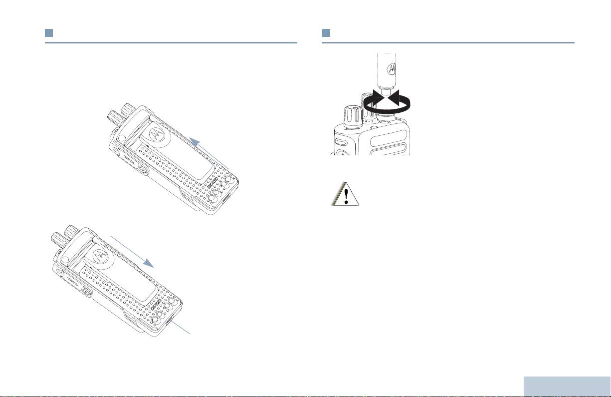
Instalación de la batería
Colocación de la antena
Preparación del radioteléfono para su uso
Alinee la batería con las guías de la parte trasera del radioteléfono.
Con el radioteléfono apagado, coloque
Presione firmemente la batería y deslícela hacia arriba hasta que el
la antena en el receptáculo y gírela en el
cierre se coloque en su lugar. Coloque el cierre de la batería en la
sentido de las agujas del reloj
.
posición de cierre.
Para quitar la antena, gírela en sentido
contrario a las agujas del reloj.
Para extraer la
batería, apague el
radioteléfono.
Desplace el cierre
de la batería hasta
la posición de
apertura y deslice
la batería hacia
abajo y sáquela de
las guías.
3
Español
Cierre
de la
batería
Si es necesario reemplazar la antena, asegúrese de
que se utilizan únicamente antenas MOTOTRBO. En
caso contrario el radioteléfono resultará dañado.
Advertencia
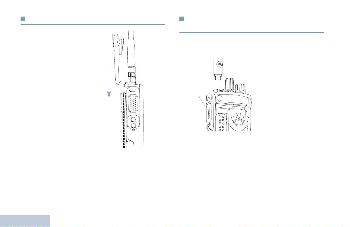
Colocación de la pinza de cinturón
Instalación de la cubierta del conector
universal (cubierta)
Alinee las ranuras de la pinza
El conector universal está situado en el lateral de la antena del
con las de la batería y empuje
radioteléfono. Se utiliza para conectar los accesorios MOTOTRBO
hacia abajo hasta que oiga un
al radioteléfono.
clic.
Inserte el extremo de la
cubierta con forma de gancho
Para quitar la pinza, saque la
en las ranuras que hay por
pestaña de la pinza de
encima del conector universal.
cinturón de la batería. Quizá le
Empuje la cubierta hacia abajo
resulte más fácil si utiliza una
para fijar la pestaña
llave. A continuación, deslice
adecuadamente en el conector
la pinza hacia arriba y
de radiofrecuencia.
extráigala del radioteléfono.
Gire el tornillo en el sentido de
las agujas del reloj para
asegurar la cubierta del
conector al radioteléfono.
Para extraer la cubierta del conector universal, empuje la cubierta
hacia abajo y gire el tornillo en el sentido contrario a las agujas del
reloj.
Sustituya la cubierta cuando no se esté utilizando el conector
universal.
Preparación del radioteléfono para su uso
4
Español
Conector
universal

Encendido del radioteléfono
Ajuste del volumen
Preparación del radioteléfono para su uso
Gire el mando de encendido/
Para aumentar el volumen, gire el Mando de encendido/apagado/
apagado/volumen en la
volumen en el sentido de las agujas del reloj.
dirección de las agujas del
reloj hasta que oiga un clic.
El indicador LED se ilumina en
verde fijo.
Suena un breve tono de
llamada, que indica que la
prueba de encendido se ha
realizado correctamente.
NOTA: No se oirá ningún tono
de encendido si la
función tonos/alertas
del radioteléfono está
desactivada (consulte
Encendido y
apagado de tonos/alertas del radioteléfono en la
página 37).
Para bajar el volumen, gire este mando en el sentido contrario a las
agujas del reloj.
Si el radioteléfono no se enciende, compruebe la batería.
Asegúrese de que está cargada y conectada correctamente. Si el
radioteléfono sigue sin encenderse, póngase en contacto con su
NOTA: Puede programar la radio para que tenga un desnivel de
distribuidor.
volumen mínimo para que el nivel del volumen no se
pueda bajar totalmente. Póngase en contacto con el
Para apagar el radioteléfono, gire este mando en el sentido
distribuidor o el administrador del sistema para obtener
contrario a las agujas del reloj hasta que oiga un clic.
más información.
5
Español
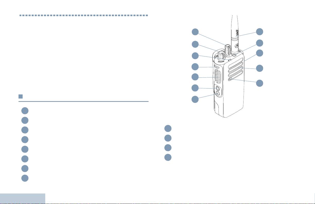
Identificación de los controles del
radioteléfono
Tómese unos minutos para revisar lo siguiente:
Controles del radioteléfono que utilizará . . . . . . . . . . . . . página 6
Botones programables. . . . . . . . . . . . . . . . . . . . . . . . . . . página 7
Botón PTT (pulsar para hablar) . . . . . . . . . . . . . . . . . . . . página 8
Cambio entre modo analógico y digital
convencionales. . . . . . . . . . . . . . . . . . . . . . . . . . . . . . . página 9
Conexión del sitio IP . . . . . . . . . . . . . . . . . . . . . . . . . . . página 10
Capacity Plus . . . . . . . . . . . . . . . . . . . . . . . . . . . . . . . . . página 10
Linked Capacity Plus . . . . . . . . . . . . . . . . . . . . . . . . . . . página 11
Controles del radioteléfono que utilizará
Mando selector de canales*
Mando de encendido/apagado/volumen
Indicador LED
Botón lateral 1*
Botón PTT (pulsar para hablar)
Botón lateral
2*
Identificación de los controles del radioteléfono
Botón lateral 3*
Micrófono
6
Español
1
2
3
4
5
6
7
8
Altavoz
Conector universal para accesorios
Botón de emergencia
*
Antena
* Estos botones son programables
1
12
2
11
10
3
4
9
5
8
6
7
9
10
11
12

Transferencia de llamadas : Activa o desactiva la transferencia de
Botones programables
llamadas.
Identificación de los controles del radioteléfono
Su distribuidor puede programar los botones programables como
Anuncio de voz para canal : Reproduce mensajes de voz de
métodos abreviados de teclado a las funciones de la radio o a los
anuncio de canal y zona para el canal actual. Esta función no está
canales/grupos predeterminados según la duración de la
disponible cuando el anuncio de voz está desactivado.
pulsación del botón:
Emergencia: dependiendo de la programación, inicia o cancela
• Pulsación corta: consiste en pulsar y soltar el botón rápidamente.
una llamada o una alarma de emergencia.
Audio inteligente encendido/apagado : Activa o desactiva el
• Pulsación larga: consiste en pulsar y mantener pulsado el botón
audio inteligente.
durante la duración programada.
‡
• Mantenimiento de la pulsación: consiste en dejar pulsado el
Navegación manual de sitios*
: inicia la búsqueda manual
botón.
de sitio.
NOTA: La duración programada de pulsación de botones se
AGC mic encendido/apagado : Activa o desactiva el control
puede aplicar a todas las funciones o configuraciones de
automático de ganancia (AGC) del micrófono interno. No disponible
la radio o utilidad asignables. Consulte Operación de
durante una sesión con Bluetooth.
emergencia en la página 27 para obtener más
Monitorización: monitoriza un canal seleccionado en busca de
información de la duración programada del botón
actividad.
Emergencia.
‡
Eliminación de canal ruidoso*
: elimina temporalmente de la
Funciones asignables del radioteléfono
lista de rastreo un canal no deseado, exceptuando el
canalseleccionado. El canal seleccionado se refiere a la
TM
Cambio audio Bluetooth
: Alterna la salida de audio entre el
combinación de zona/canal seleccionada por el usuario desde la
altavoz interno del radioteléfono y el accesorio externo con
que se inicia el rastreo.
tecnología Bluetooth.
Acceso de marcación rápida : Inicia directamente una
Conectar Bluetooth : Inicia una operación de detección y
conexión de Bluetooth.
llamada privada o de grupo, una alerta de llamada o un mensaje
con notas rápidas predeterminados.
Desconectar Bluetooth : Cierra todas las conexiones de
Bluetooth existentes entre el radioteléfono y cualquier dispositivo
con tecnología Bluetooth.
7
Español
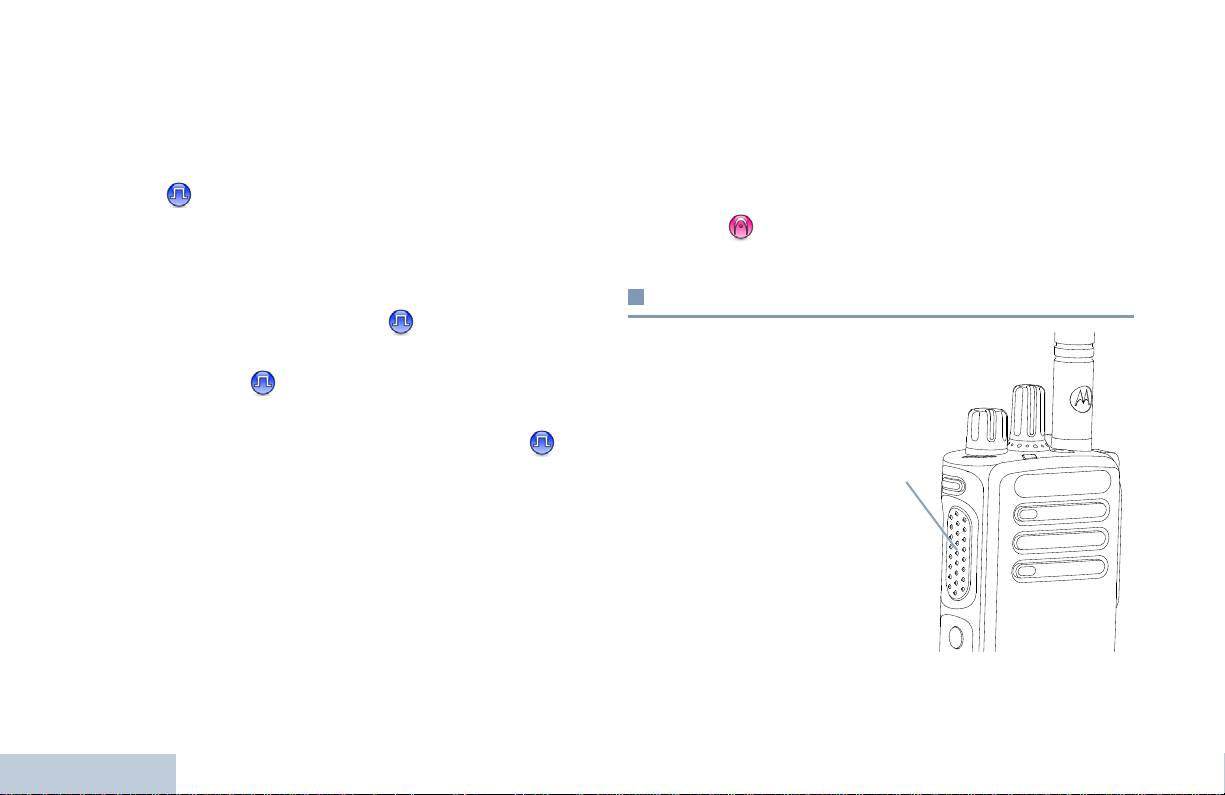
Función de tarjeta opcional : activa o desactiva las funciones de
Funciones asignables de configuración o
tarjeta opcional para los canales compatibles con la tarjeta
herramientas
opcional.
Todos los tonos/alertas: activa y desactiva todos los tonos y
‡
Monitor permanente*
: muestra un canal seleccionado por todo
alertas.
el tráfico de radioteléfonos hasta que se desactiva la función.
Nivel de potencia: alterna entre los niveles de potencia de
Privacidad : activa o desactiva la privacidad.
transmisión alto y bajo.
‡
Repetidor/Modo directo*
: alterna entre el uso de un repetidor y
Silenciador
: alterna el nivel del silenciador entre cerrado y
la comunicación directa con otro radioteléfono.
normal.
‡
Rastreo*
: enciende y apaga el rastreo.
Botón PTT (pulsar para hablar)
Bloqueo del sitio encendido/apagado* : activa o desactiva
la navegación automática de sitios.
El botón PTT situado a un
lateral del radioteléfono
Control de telemetría : controla la clavija de salida en un
tiene dos funciones
radioteléfono local o remoto.
principales:
Desactivación remota de la interrupción de transmisión :
• Mientras haya una
D
etiene una llamada interrumpible en curso para liberar el canal.
llamada en curso, el
Anuncio de voz activado/desactivado : Activa o desactiva el
botón PTT permite que el
anuncio de voz.
radioteléfono transmita a
otros radioteléfonos
Transmisión por voz (VOX) : activa o desactiva la VOX.
durante la llamada.
Zona : permite seleccionar entre una lista de zonas.
Carga de la batería : Informa sobre la carga de la batería a través
Mantenga pulsado el
del indicador LED
.
botón PTT para hablar.
Identificación de los controles del radioteléfono
Suelte el botón PTT para
escuchar.
El micrófono se activa cuando se pulsa el botón PTT.
8
Español
* No disponible en Capacity Plus
‡
No disponible en Linked Capacity Plus
Botón
PTT

• Cuando no hay ninguna llamada en curso, el botón PTT se utiliza
Cambio entre modo analógico y digital
para realizar una nueva llamada (consulte Realización de una
convencionales
Identificación de los controles del radioteléfono
llamada de radioteléfono en la página 18).
Cada canal del radioteléfono
En función de la programación, si está activado el tono de
autorización para hablar o el efecto local de PTT , espere hasta
se puede configurar como un
que acabe el tono de alerta breve antes de empezar a hablar.
canal analógico convencional
o un canal digital
Durante una llamada, si la función Indicación de canal libre
convencional. Utilice el
está activada en el radioteléfono (si está programado por su
mando selector de canales
distribuidor), escuchará un tono de alerta corto en el momento
para cambiar entre un canal
en el que el radioteléfono de destino (el radioteléfono que
analógico o uno digital.
recibe la llamada) suelte el botón PTT, indicando así que el
Al cambiar de modo digital a
canal queda libre para responder.
modo analógico, algunas
funciones dejarán de estar
También escuchará un tono continuo de prohibición para
disponibles.
hablar si se interrumpe la llamada, que le indica que debería
El radioteléfono también tiene funciones disponibles para los
soltar el botón PTT, por ejemplo, si el radioteléfono recibe una
modos analógico y digital. Sin embargo, las pequeñas diferencias
llamada de emergencia.
en la forma de funcionar de cada función NO afectan al
funcionamiento del radioteléfono.
NOTA: El radioteléfono también cambia entre los modos
analógico y digital durante un rastreo de modo doble
(consulte Rastreo en la página 24).
9
Español
Mando Selector de
canales

No puede añadir ni borrar manualmente una entrada de la lista de
Conexión del sitio IP
navegación. Póngase en contacto con el distribuidor o el
administrador del sistema para obtener más información.
Esta función permite que su radioteléfono amplíe la comunicación
convencional más allá del alcance de un solo sitio mediante la
conexión a diferentes sitios disponibles conectados a través de una
Capacity Plus
red de protocolo de Internet (IP).
Cuando un radioteléfono está fuera de cobertura respecto a un sitio
Capacity Plus es una configuración normal de un solo sitio del
y entra en la de otro, se conecta al nuevo repetidor del sitio para
sistema de radioteléfono MOTOTRBO, que utiliza un conjunto de
enviar o recibir transmisiones de datos o llamadas. Según la
canales para que sea compatible con cientos de usuarios y hasta
configuración, esto se realiza de forma automática o manual.
254 grupos. Esta función permite que el radioteléfono utilice de
forma eficaz el número disponible de canales programados
Si el radioteléfono está configurado para hacerlo automáticamente,
mientras se encuentra en el Modo Repetidor.
busca todos los sitios disponibles cuando la señal del sitio actual
sea débil o cuando el radioteléfono no pueda detectar ninguna
Los iconos de las funciones no disponibles para Capacity Plus no
señal del sitio actual. A continuación se ajusta al repetidor con el
estarán disponibles en el menú. Oirá un tono indicador negativo si
valor Indicador de intensidad de señal recibida (RSSI) más fuerte.
accede a una función que no esté disponible en Capacity Plus a
través de una pulsación de un botón programable.
En una búsqueda manual de sitio, el radioteléfono busca el
siguiente sitio de la lista de navegación que tiene cobertura en ese
El radioteléfono también tiene funciones que están disponibles en
momento (aunque tal vez no sea la señal más fuerte) y se
el modo digital convencional, IP Site Connect, Capacity Plus y
ajusta a él.
Linked Capacity Plus. Sin embargo, las pequeñas diferencias en la
forma de funcionar de cada función NO afectan al funcionamiento
NOTA: Cada canal sólo puede tener activado el rastreo o la
del radioteléfono.
navegación, pero no ambas opciones al mismo tiempo.
Póngase en contacto con el distribuidor o el administrador del
Los canales que tengan esta función activada pueden añadirse a
sistema para obtener más información sobre esta configuración.
luna lista de navegación particular. El radioteléfono busca los
canales en la lista de navegación durante la operación de
Identificación de los controles del radioteléfono
navegación automática para localizar el mejor sitio.
Una lista de navegación admite un máximo de 16 canales (incluido
el canal seleccionado).
10
Español

Cualquier canal con Linked Capacity Plus activada puede añadirse
Linked Capacity Plus
a una lista de navegación particular. El radioteléfono busca esos
canales durante la operación de navegación automática para
Identificación de los controles del radioteléfono
Linked Capacity Plus es una configuración normal de varios sitios y
localizar los mejores sitios.
varios canales del sistema de radioteléfono MOTOTRBO que
combina lo mejor de las configuraciones Capacity Plus e
NOTA: No puede añadir ni borrar manualmente una entrada de la
IP Site Connect.
lista de navegación. Póngase en contacto con el
distribuidor o el administrador del sistema para obtener
Linked Capacity Plus permite que su radioteléfono amplíe la
más información.
comunicación normal más allá del alcance de un solo sitio
mediante la conexión a diferentes sitios disponibles conectados a
De forma similar a Capacity Plus, los iconos de las funciones que
través de una red de protocolo de Internet (IP). También
no son aplicables a Linked Capacity Plus no están disponibles en el
proporciona una capacidad superior gracias al uso eficiente del
menú. Escucha un tono indicador negativo si intenta acceder a una
número disponible de canales programados combinados que
función que no esté disponible en Linked Capacity Plus a través de
admite cada uno de los sitios disponibles.
una pulsación de un botón programable.
Cuando un radioteléfono está fuera de cobertura respecto a un sitio
Póngase en contacto con el distribuidor o el administrador del
y entra en la de otro, se conecta al nuevo repetidor del sitio para
sistema para obtener más información sobre esta configuración.
enviar o recibir transmisiones de datos o llamadas. Según la
configuración, esto se realiza de forma automática o manual.
Si el radioteléfono está configurado para hacerlo automáticamente,
busca todos los sitios disponibles cuando la señal del sitio actual
sea débil o cuando el radioteléfono no pueda detectar ninguna
señal del sitio actual. A continuación se ajusta al repetidor con el
valor Indicador de intensidad de señal recibida (RSSI) más fuerte.
En una búsqueda manual de sitio, el radioteléfono busca el
siguiente sitio de la lista de navegación que tiene cobertura en ese
momento (aunque tal vez no sea la señal más fuerte) y se
ajusta a él.
11
Español
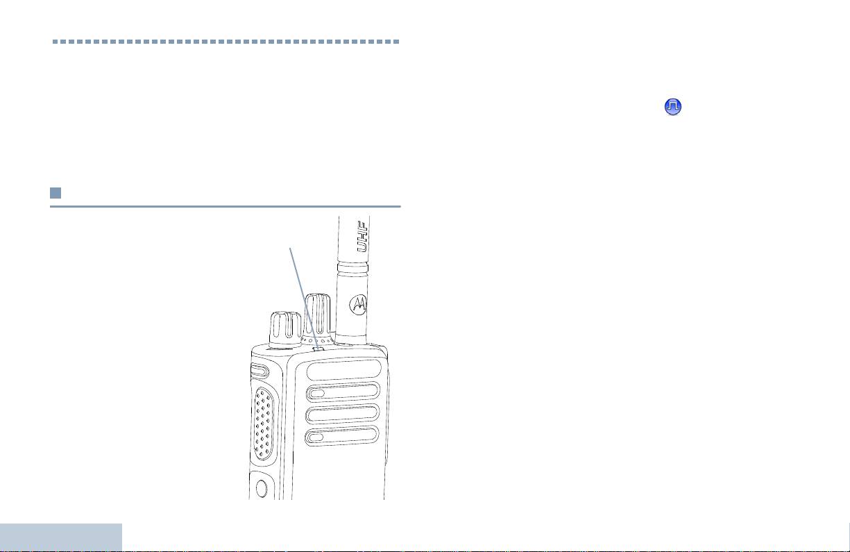
Verde intermitente: El radioteléfono está recibiendo una llamada o
Identificación de los indicadores
datos que no tienen la privacidad activada, o bien está detectando
actividad por el aire.
de estado
Verde intermitente rápido: El radioteléfono está recibiendo una
El radioteléfono indica su estado de funcionamiento a través de lo
llamada o datos con la privacidad activada .
siguiente:
Amarillo fijo: El radioteléfono está monitorizando un canal
Indicador LED . . . . . . . . . . . . . . . . . . . . . . . . . . . . . . . . página 12
convencional. También indica una carga de batería regular cuando
Tonos de audio. . . . . . . . . . . . . . . . . . . . . . . . . . . . . . . . página 13
el botón Carga de la batería está pulsado.
Tonos de indicador. . . . . . . . . . . . . . . . . . . . . . . . . . . . . página 13
Amarillo intermitente: El radioteléfono busca actividad o recibe
una llamada de aviso, o todos los canales locales de Linked
Indicador LED
Capacity Plus están ocupados.
Amarillo intermitente rápido: El radioteléfono ya no está
El indicador LED muestra el
conectado al repetidor mientras está en Capacity Plus o en Linked
estado de funcionamiento del
Capacity Plus, todos los canales de Capacity Plus o los canales de
radioteléfono.
Linked Capacity Plus están ocupados, la itinerancia automática
Rojo intermitente: El
está activada o el radioteléfono está buscando activamente un
radioteléfono transmite con un
nuevo sitio. También indica que el radioteléfono tiene que
nivel de batería bajo, recibe una
responder aún a una alerta de llamada de grupo o que está en
transmisión de emergencia o se
estado de bloqueo.
ha producido un error en la
NOTA: En modo convencional, cuando el indicador LED
autocomprobación que se realiza
parpadea en verde, indica que el radioteléfono detecta
durante el encendido.
actividad por el aire. A causa de la naturaleza del
Verde fijo: El radioteléfono está
protocolo digital, puede que esta actividad afecte al canal
encendiéndose o transmitiendo.
programado del radioteléfono.
También indica una carga de
batería regular cuando el botón
En Capacity Plus y Linked Capacity Plus, no hay
Identificación de los indicadores de estado
Carga de la batería está
indicación LED cuando el radioteléfono está detectando
pulsado.
actividad por el aire.
12
Español
Indicador LED
Tonos de indicador
Tonos de audio
Identificación de los indicadores de estado
Los tonos de alerta le proporcionan indicaciones audibles del
Tono agudo Tono grave
estado del radioteléfono o de la respuesta del radioteléfono a los
datos recibidos.
Tono indicador positivo
Tono continuo
Un sonido monótono. Suena
continuadamente hasta que finaliza.
Tono indicador negativo
Tono periódico
Suena periódicamente dependiendo de la
duración que haya establecido el
radioteléfono. El tono empieza, se para y
se repite.
Tono repetitivo
Suena un único tono que se repite hasta
que lo apaga el usuario.
Tono momentáneo
Suena sólo una vez durante un corto
período de tiempo establecido por el
radioteléfono.
13
Español

Selección de un canal
Realización y recepción de llamadas
Las transmisiones se envían y reciben en un canal. En función de
Una vez que haya entendido cómo está configurado su dispositivo
la configuración del radioteléfono, cada canal se puede programar
portátil MOTOTRBO, ya está listo para utilizar el radioteléfono.
de forma distinta para admitir grupos de usuarios distintos o con
Utilice esta guía de navegación para familiarizarse con las
funciones diferentes. Después de seleccionar la zona deseada,
funciones básicas de llamada:
seleccione el canal al que desea asignar la transmisión o la
Selección de zonas . . . . . . . . . . . . . . . . . . . . . . . . . . . . página 14
recepción.
Selección de un canal . . . . . . . . . . . . . . . . . . . . . . . . . . página 14
Recepción y respuesta a llamadas de
radioteléfonos. . . . . . . . . . . . . . . . . . . . . . . . . . . . . . . página 15
Realización de una llamada de radioteléfono . . . . . . . . página 18
Cómo detener una llamada de radio . . . . . . . . . . . . . . . página 21
Modo directo . . . . . . . . . . . . . . . . . . . . . . . . . . . . . . . . . página 21
Funciones de monitorización . . . . . . . . . . . . . . . . . . . . . página 22
Selección de zonas
Una zona es un grupo de canales. Su radioteléfono admite hasta
32 canales y 2 zonas, con un máximo de 16 canales por zona.
Procedimiento:
Procedimiento:
1 Pulse el botón programado como Zona.
Gire el mando selector de canales para seleccionar el canal con
el ID o alias de grupo activo.
2 Oirá un tono indicador positivo, que indica que la radio ha
cambiado de la zona 1 a la zona 2.
Realización y recepción de llamadas
O
Oirá un tono indicador negativo, que indica que la radio ha
cambiado de la zona 2 a la zona 1.
14
Español
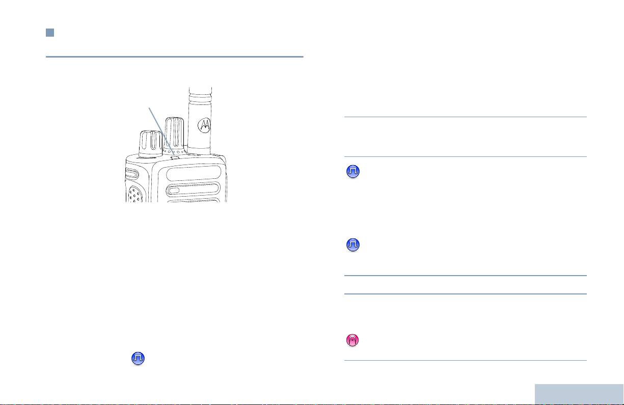
Recepción y respuesta a llamadas de
Recepción y respuesta a llamadas de grupo
radioteléfonos
Para recibir una llamada de un grupo de usuarios, el radioteléfono
Realización y recepción de llamadas
deberá estar configurado como parte de ese grupo.
Una vez que se haya mostrado el canal, el ID de suscriptor o el ID
Procedimiento:
de grupo, podrá recibir y responder a llamadas.
1 El indicador LED parpadea en verde. El radioteléfono desactiva
el silencio y las llamadas entrantes suenan a través del altavoz
del radioteléfono.
2 Para responder, mantenga el radioteléfono en posición vertical
a una distancia de entre 2,5 y 5 cm (de 1 a 2 pulgadas) de la
boca.
3 Si la función Indicación de canal libre está activada,
escuchará un tono de alerta corto en el momento en el que el
radioteléfono de destino suelte el botón PTT, indicando así que
el canal queda libre para responder.
El indicador LED se ilumina en verde fijo mientras el radioteléfono
Pulse el botón PTT para responder la llamada.
está transmitiendo y parpadea cuando está recibiendo.
O
NOTA: El indicador LED se ilumina en verde fijo mientras el
radioteléfono está transmitiendo y parpadea rápido en
Si la función de interrupción de voz está activada, pulse el
verde cuando está recibiendo una llamada que tiene la
botón PTT para detener la llamada actual de la radio
privacidad activada.
transmisora y liberar el canal para poder hablar o responder.
Para descodificar una llamada que tiene la privacidad
4 El indicador LED se ilumina en verde fijo.
activada, el radioteléfono debe tener la misma clave de
privacidad O los mismos valor clave e ID clave
5 Espere hasta que acabe el tono Permitir hablar (si está
(programado por el distribuidor) que el transmisor de radio
habilitado) y hable con claridad al micrófono..
(el radioteléfono desde el que recibe la llamada).
O
Espere a que finalice el efecto local de PTT (si está
Consulte Privacidad en la página 31 para obtener más
activado) y hable al micrófono de forma clara.
información.
15
Español
Indicador LED

6 Suelte el botón PTT para escuchar.
5 Espere hasta que acabe el tono Permitir hablar (si está
habilitado) y hable con claridad al micrófono.
7 Si no hay actividad de voz durante un período de tiempo
6 Suelte el botón PTT para escuchar.
predeterminado, la llamada finalizará.
7 Si no hay actividad de voz durante un período de tiempo
Consulte Realización de llamadas de grupo en la página 18 para
predeterminado, la llamada finalizará.
obtener detalles sobre la realización de llamadas de grupo.
8 Sonará un tono corto.
Consulte Realización de llamadas privadas en la página 19 para
Recepción y respuesta a llamadas privadas
obtener detalles sobre la realización de llamadas privadas.
Una llamada privada es una llamada de un radioteléfono individual
a otro radioteléfono individual.
Procedimiento:
Cuando recibe una llamada privada:
1 El indicador LED parpadea en verde. El radioteléfono desactiva
el silencio y las llamadas entrantes suenan a través del altavoz
del radioteléfono.
2 Para responder, mantenga el radioteléfono en posición vertical
a una distancia de entre 2,5 y 5 cm (de 1 a 2 pulgadas) de la
boca.
3 Si la función Indicación de canal libre está activada, escuchará
un tono de alerta corto en el momento en el que el radioteléfono
de destino suelte el botón PTT, indicando así que el canal
queda libre para responder.
O
Si la función de interrupción de voz está activada, pulse el
botón PTT para detener la llamada actual de la radio
Realización y recepción de llamadas
transmisora y liberar el canal para poder hablar o responder.
4 Pulse el botón PTT para responder la llamada. El indicador
LED se ilumina en verde fijo.
16
Español

Recepción de llamadas de todos
Recepción y respuesta a una llamada selectiva
Una llamada de todos es una llamada de un radioteléfono
Una llamada selectiva es una llamada de un radioteléfono
Realización y recepción de llamadas
individual a todos los radioteléfonos del canal. Se utiliza para
individual a otro radioteléfono individual. Se trata de una llamada
realizar anuncios importantes que requieren de la atención total del
privada en un sistema analógico.
usuario.
Procedimiento:
Procedimiento:
Cuando recibe una llamada selectiva:
Cuando recibe una llamada de todos:
1 El indicador LED parpadea en verde.
1 Suena un tono y el indicador LED parpadea en verde. El
2 Mantenga el radioteléfono en posición vertical a una distancia
radioteléfono desactiva el silencio y las llamadas entrantes
de entre 2,5 y 5 cm (de 1 a 2 pulgadas) de la boca. El
suenan a través del altavoz del radioteléfono.
radioteléfono desactiva el silencio y las llamadas entrantes
suenan a través del altavoz del radioteléfono.
2 Si no hay actividad de voz durante un período de tiempo
predeterminado, finalizará la llamada de todos. Una llamada de
3 Si la función Indicación de canal libre está activada, escuchará
todos no espera un período de tiempo predeterminado antes de
un tono de alerta corto en el momento en que el radioteléfono
finalizar.
de transmisión suelte el botón PTT, indicando así que el canal
queda libre para responder.
Si la función Indicación de canal libre está activada,
4 Pulse el botón PTT para responder a la llamada. El indicador
escuchará un tono de alerta corto en el momento en el que el
LED se ilumina en verde fijo.
radioteléfono de destino suelte el botón PTT, indicando así que
el canal queda libre para responder.
5 Espere hasta que deje de sonar el Tono permitir hablar (si está
activado) y hable con claridad al micrófono.
No puede responder a una llamada de todos.
6 Suelte el botón PTT para escuchar.
NOTA: El radioteléfono deja de recibir la llamada de todos si
7 Si no hay actividad de voz durante un período de tiempo
cambia a un canal distinto mientras está recibiendo la
predeterminado, la llamada finalizará.
llamada.
Durante una llamada de todos, no podrá utilizar ningún
8 Sonará un tono corto.
botón programado hasta que finalice la llamada.
Consulte Realización de una llamada selectiva en la página 19
para obtener detalles sobre la realización de una llamada selectiva.
17
Español

Procedimiento:
Realización de una llamada d
e
radioteléfono
1 Seleccione el canal con el ID o alias de grupo activo. Consulte
Después de seleccionar el canal, puede seleccionar un ID o alias
Selección de un canal en la página 14.
de suscriptor, o el ID o alias de grupo mediante el uso de:
O
Pulse el botón de acceso de marcación rápida programado.
• El mando selector de canales
2 Mantenga el radioteléfono en posición vertical a una distancia
• Un botón programado Acceso de marcación rápida
de entre 2,5 y 5,0 cm (de 1 a 2 pulgadas) de la boca.
NOTA: El radioteléfono debe tener la función Privacidad activada
3 Pulse el botón PTT para realizar la llamada. El indicador LED
en el canal para enviar una transmisión con la privacidad
se ilumina en verde fijo.
activada. Únicamente los radioteléfonos de destino que
posean la misma clave de privacidad O el mismo valor
4 Espere hasta que acabe el tono Permitir hablar (si está
clave e ID clave que su radioteléfono podrán descodificar
habilitado) y hable con claridad al micrófono.
la transmisión
O
Espere a que finalice el efecto local de PTT (si está
Consulte Privacidad en la página 31 para obtener más
activado) y hable al micrófono de forma clara.
información.
5 Suelte el botón PTT para escuchar. Cuando el radioteléfono al
que se llama responda, el indicador LED parpadeará en verde.
La función de acceso de marcación rápida permite
realizar fácilmente una llamada privada o de grupo a un
6 Si la función Indicación de canal libre está activada, escuchará
ID predeterminado. Esta función solo se puede asignar a
un tono de alerta corto en el momento en el que el radioteléfono
una pulsación de botón programable corta o larga.
de destino suelte el botón PTT, indicando así que el canal
ÚNICAMENTE puede haber un ID asignado a un botón
queda libre para responder. Pulse el botón PTT para
de acceso de marcación rápida. El radioteléfono tiene
responder.
programados varios botones de acceso de marcación
O
rápida.
Si no hay actividad de voz durante un período de tiempo
predeterminado, la llamada finalizará.
Realización de una llamada con el mando selector
de canales
Realización y recepción de llamadas
Realización de llamadas de grupo
Para llamar a un grupo de usuarios, el radioteléfono deberá estar
configurado como parte de ese grupo.
18
Español

4 Espere hasta que acabe el tono Permitir hablar (si está
Realización de llamadas privadas
habilitado) y hable con claridad al micrófono.
Mientras que puede recibir o responder a una llamada privada
Realización y recepción de llamadas
5 Suelte el botón PTT para escuchar. Cuando el radioteléfono al
iniciada a través de un radioteléfono individual autorizado, su
que se llama responda, el indicador LED parpadeará en verde.
radioteléfono deberá estar programado para que pueda iniciar una
6 Si la función Indicación de canal libre está activada, escuchará
llamada privada.
un tono de alerta corto en el momento en el que el radioteléfono
Hay dos tipos de llamadas privadas. El primer tipo consiste en una
de destino suelte el botón PTT, indicando así que el canal
verificación de presencia de radioteléfono que se realiza antes de
queda libre para responder. Pulse el botón PTT para responder.
configurar la llamada, mientras que el otro tipo configura la llamada
O
inmediatamente.
Si no hay actividad de voz durante un período de tiempo
Su distribuidor solo puede programar uno de esos tipos de
predeterminado, la llamada finalizará.
llamadas en su radioteléfono.
7 Sonará un tono corto.
Si no está activada esta función, oirá un tono indicador negativo
cuando realice una llamada privada a través del botón Acceso de
marcación rápida o el mando selector de canales.
Realización de una llamada selectiva
Utilice las funciones Mensaje de texto rápido o Alerta de llamada
Al igual que con una llamada privada, mientras que puede recibir o
para contactar con un radioteléfono individual. Consulte las
responder a una llamada selectiva iniciada a través de un
Características de mensajería en la página 30 o
radioteléfono individual autorizado, su radioteléfono deberá estar
Funcionamiento de las alertas de llamada on página 26 para
programado para que pueda iniciar una llamada selectiva.
obtener más información.
Procedimiento:
Procedimiento:
1 Seleccione el canal con el ID o alias de grupo activo. Consulte
1 Seleccione el canal con el ID o alias de grupo activo. Consulte
Selección de un canal en la página 14.
Selección de un canal en la página 14.
O
2 Mantenga el radioteléfono en posición vertical a una distancia
Pulse el botón de acceso de marcación rápida programado.
de entre 2,5 y 5,0 cm (de 1 a 2 pulgadas) de la boca.
2 Mantenga el radioteléfono en posición vertical a una distancia
de entre 2,5 y 5,0 cm (de 1 a 2 pulgadas) de la boca.
3 Pulse el botón PTT para realizar la llamada. El indicador LED
se ilumina en verde fijo.
3 Pulse el botón PTT para realizar la llamada. El indicador LED
se ilumina en verde fijo.
19
Español

4 Espere hasta que acabe el tono Permitir hablar (si está
4 Espere hasta que acabe el tono Permitir hablar (si está
habilitado) y hable con claridad al micrófono.
habilitado) y hable con claridad al micrófono.
O
5 Suelte el botón PTT para escuchar. Cuando el radioteléfono al
que se llama responda, el indicador LED parpadeará en verde.
Espere a que finalice el efecto local de PTT (si está
activado) y hable al micrófono de forma clara.
6 Si la función Indicación de canal libre está activada, escuchará
un tono de alerta corto en el momento en el que el radioteléfono
Los usuarios del canal no pueden responder a una llamada de
de destino suelte el botón PTT, indicando así que el canal
todos.
queda libre para responder. Pulse el botón PTT para responder.
O
Si no hay actividad de voz durante un período de tiempo
predeterminado, la llamada finalizará.
7 Sonará un tono corto.
Realización de llamadas de todos
Esta función permite que transmita a todos los usuarios del canal.
El radioteléfono debe estar programado para que pueda utilizarse
esta función.
Procedimiento:
1 Seleccione el canal con el ID o alias de grupo activo. Consulte
Selección de un canal en la página 14.
2 Mantenga el radioteléfono en posición vertical a una distancia
de entre 2,5 y 5,0 cm (de 1 a 2 pulgadas) de la boca.
3 Pulse el botón PTT para realizar la llamada. El indicador LED
Realización y recepción de llamadas
se ilumina en verde fijo.
20
Español

Modo directo
Cómo detener una llamada de radio
Realización y recepción de llamadas
Puede seguir comunicándose cuando el repetidor no esté
Esta función permite detener una llamada privada o a grupo con el
funcionando, o cuando el radioteléfono esté fuera de la cobertura
fin de liberar el canal para la transmisión. Por ejemplo, cuando una
del repetidor pero dentro de la cobertura de otros radioteléfonos.
radio experimenta una situación de «micrófono atascado» en la
Esto se llama «modo directo».
que el usuario pulsa sin darse cuenta el botón PTT.
NOTA: Esta función no está disponible en Capacity Plus ni
La radio debe estar programada para poder utilizar esta función.
Linked Capacity Plus.
Procedimiento:
Procedimiento:
Cuando esté situado en el canal requerido:
1 Pulse el botón que ha programado previamente como
1 Pulse el botón programado Desactivación remota de la
Repetidor/Modo directo.
interrupción de transmisión.
2 Oirá un tono indicador positivo que informará de que el
2 Espere a que se produzca la confirmación.
radioteléfono está en el modo directo.
U
3 El radioteléfono emitirá un tono indicador positivo para informar
Oirá un tono indicador negativo, que informará de que el
de que el canal está libre.
radioteléfono se encuentra en modo de repetidor.
O
El radioteléfono emitirá un tono indicador negativo para
La configuración del modo directo se mantiene incluso después de
informar de que el radioteléfono no puede liberar el canal.
haber apagado el radioteléfono.
El radioteléfono emitirá un tono indicador negativo hasta que suelte
el botón PTT, si está transmitiendo una llamada interrumpible que
se detenga con esta función. En los radioteléfonos interrumpidos
con pantalla, aparecerá un mensaje que indicará
Llamd. interrump.
21
Español

Funciones de monitorización
Monitor permanente
Utilice la función Monitor permanente para monitorizar si existe
actividad en un canal seleccionado.
Monitorización de un canal
NOTA: Esta función no está disponible en Capacity Plus ni
Utilice la función de monitorización para asegurarse de que un
Linked Capacity Plus.
canal está libre antes de transmitir.
Procedimiento:
NOTA: Esta función no está disponible en Capacity Plus ni
Linked Capacity Plus.
1 Pulse el botón que ha programado previamente como Monitor
permanente.
Procedimiento:
1 Mantenga pulsado el botón preprogramado Monitorización y
2 Suena un tono de alerta en el radioteléfono, el LED se ilumina
escuche para ver si hay actividad.
en amarillo fijo.
2 Oirá actividad en el radioteléfono o silencio total, dependiendo
3 Pulse el botón que ha programado como Monitor permanente
de cómo esté programado el radioteléfono.
para salir del modo de monitor permanente.
3 Cuando oiga un «ruido blanco» (es decir, que el canal está
4 Suena un tono de alerta en el radioteléfono y el indicador LED
libre), pulse el botón PTT para hablar y suéltelo par escuchar.
se apaga.
El LED se ilumina en amarillo fijo.
Realización y recepción de llamadas
22
Español

Listas de rastreo
Funciones avanzadas
Funciones avanzadas
Las listas de rastreo se crean y asignan a canales/grupos
Utilice esta guía a la navegación para conocer mejor las
individuales. El radioteléfono busca actividad de voz alternando
características superiores de su radioteléfono:
entre la secuencia canal/grupo especificada en la lista de rastreo
Listas de rastreo. . . . . . . . . . . . . . . . . . . . . . . . . . . . . . . página 23
del actual canal/grupo.
Rastreo. . . . . . . . . . . . . . . . . . . . . . . . . . . . . . . . . . . . . . página 24
El radioteléfono admite hasta 250 listas de rastreo, con un máximo
Config. radio del indicador de llamadas . . . . . . . . . . . . . página 26
de 16 miembros en cada lista. Cada lista de rastreo admite una
Funcionamiento de las alertas de llamada. . . . . . . . . . . página 26
combinación de entradas analógicas y digitales.
Operación de emergencia . . . . . . . . . . . . . . . . . . . . . . . página 27
NOTA: Esta función no está disponible en Capacity Plus ni Linked
Características de mensajería . . . . . . . . . . . . . . . . . . . . página 30
Capacity Plus.
Privacidad. . . . . . . . . . . . . . . . . . . . . . . . . . . . . . . . . . . . página 31
Controles de varios sitios . . . . . . . . . . . . . . . . . . . . . . . . página 32
Operario aislado. . . . . . . . . . . . . . . . . . . . . . . . . . . . . . . página 33
Funciones de bloqueo por contraseña. . . . . . . . . . . . . . página 33
Bluetooth . . . . . . . . . . . . . . . . . . . . . . . . . . . . . . . . . . . . página 34
Herramientas . . . . . . . . . . . . . . . . . . . . . . . . . . . . . . . . . página 36
23
Español

Rastreo
Inicio y parada del rastreo
Procedimiento:
Cuando inicie un rastreo, el radioteléfono alterna entre la lista de
rastreo preprogramada del canal actual y busca actividad de voz.
1 Pulse el botón preprogramado Rastreo.
O
El indicador LED parpadea en amarillo.
Utilice el mando selector de canales para seleccionar un canal
Durante un rastreo de modo doble, si se encuentra en un canal
activando el rastreo automático .
digital y el radioteléfono está bloqueado en un canal analógico,
2 Cuando el rastreo esté activado, el indicador LED parpadeará y
cambiará automáticamente del modo digital al analógico durante la
llamada. Esto también sucede en la situación inversa.
se emitirá un tono indicador positivo.
O
Hay dos formas de iniciar el rastreo:
Cuando esté desactivado el rastreo, el indicador LED se
• Rastreo de canal principal (manual): El radioteléfono busca
apagará
todos los canales/grupos de su lista de rastreo. Para empezar el
rastreo, el radioteléfono puede (según la configuración) empezar
Respuesta a una transmisión durante un rastreo
automáticamente en el canal/grupo «activo» en el que se realizó
Durante el rastreo, el radioteléfono se detiene en un canal/grupo en
el último rastreo o en el canal en el que se inició el rastreo.
el que detecte actividad. El radioteléfono se mantiene en ese canal
• Rastreo automático (automático): El radioteléfono empieza el
durante un período de tiempo predeterminado, conocido como
rastreo automáticamente al seleccionar un canal/grupo que tiene
«tiempo muerto».
activado el rastreo automático.
Procedimiento:
NOTA: Esta función no está disponible en Capacity Plus ni Linked
1 Mantenga el radioteléfono en posición vertical a una distancia
Capacity Plus.
de entre 2,5 y 5,0 cm (de 1 a 2 pulgadas) de la boca.
Si la función Indicación de canal libre está activada,
escuchará un tono de alerta corto en el momento en el que el
radioteléfono transmisor suelte el botón PTT, indicando así que
el canal queda libre para responder.
Funciones avanzadas
2 Pulse el botón PTT durante el tiempo muerto. El indicador LED
se ilumina en verde fijo.
24
Español

3 Espere hasta que acabe el tono Permitir hablar (si está
Restauración de un canal ruidoso
habilitado) y hable con claridad al micrófono.
Procedimiento:
O
Funciones avanzadas
Para restaurar un canal ruidoso eliminado, realice una de las
Espere a que finalice el efecto local de PTT (si está
siguientes acciones:
activado) y hable al micrófono de forma clara.
• Apague la radio y enciéndala de nuevo, O
4 Suelte el botón PTT para escuchar.
• Pare y vuelva a iniciar un rastreo mediante el menú o el botón
5 Si no responde dentro del período de tiempo muerto, el
preprogramado Rastreo, O
radioteléfono vuelve a realizar el rastreo de otros canales/
• Cambie el canal mediante el mando selector de canales.
grupos.
Eliminación de canales ruidosos
Rastreo de aceptación
Si un canal produce llamadas no deseadas o ruidos de forma
continua (lo que se llama un canal con «perturbaciones»), se
Rastreo de aceptación le proporciona un área amplia de cobertura
puede eliminar temporalmente de la lista de rastreo.
en zonas donde hay múltiples estaciones base transmitiendo
información idéntica en distintos canales analógicos.
Esta posibilidad no se aplica al canal designado como canal
seleccionado.
El radioteléfono rastrea canales analógicos de múltiples estaciones
base y lleva a cabo un proceso de votación para seleccionar la
Procedimiento:
señal de recepción de mayor intensidad. Una vez establecida la
1 Cuando el radioteléfono bloquea un canal no deseado o un
señal, el radioteléfono desactiva el silencio en las transmisiones
canal ruidoso, pulse el botón Eliminación de canal ruidoso
desde la estación base.
hasta que oiga un tono.
El indicador LED amarillo parpadeará durante el rastreo de la
2 Suelte el botón Eliminación de canal ruidoso. El canal
aceptación.
ruidoso se elimina.
Para responder a una transmisión durante un rastreo de
aceptación, siga los mismos procedimientos que se indican en la
sección Respuesta a una transmisión durante un rastreo en la
página 24.
25
Español

Config. radio del indicador de llamadas
Cómo realizar una alerta de llamada con el botón
Acceso de marcación rápida
Puede encender o apagar los tonos de timbre de una llamada
Procedimiento:
privada (consulte Encendido y apagado de tonos/alertas del
1 Pulse el botón programado Acceso de marcación rápida para
radioteléfono en la página 37).
realizar una alerta de llamada a un ID predefinido.
Aumento del volumen del tono de alarma
2 El LED se ilumina en verde fijo cuando el radioteléfono envía la
alerta de llamada.
Puede programar su radioteléfono para que le avise continuamente
cada vez que una llamada se quede sin responder. Esto se hace
3 Si se recibe la confirmación de llamada de alerta, sonarán dos
automáticamente al aumentar el volumen del tono de alarma por
pitidos.
encima del tiempo.
O
Si no se recibe la confirmación de llamada de alerta, sonará un
Esta función se conoce como Escalert.
tono grave.
Funcionamiento de las alertas de llamada
Los avisos de alerta de llamada le permiten avisar a un usuario
determinado de radioteléfono para que vuelva a llamarle cuando
pueda. Se puede acceder a esta función mediante un botón
programado Acceso de marcación rápida.
Recepción y respuesta a una alerta de llamada
Procedimiento:
Cuando recibe un aviso de llamada:
1 Se oye un tono repetitivo. El indicador LED parpadea en
amarillo.
Funciones avanzadas
2 Pulse el botón PTT antes de cuatro (4) segundos después de
recibir una página de alerta de llamada para responder a la
llamada privada.
26
Español

• Silencioso: el radioteléfono transmite una señal de alarma sin
Operación de emergencia
mostrar indicadores visuales o de audio. La radio recibirá
llamadas sin que el altavoz de la radio emita ningún sonido hasta
Funciones avanzadas
La alarma de emergencia se utiliza para informar de una situación
que pulse el botón PTT para iniciar la llamada.
crítica. Puede iniciar una Emergencia en cualquier momento desde
todas las pantallas incluso cuando haya actividad en el canal
• Silencioso con voz: el radioteléfono transmite una señal de
actual.
alarma sin mostrar indicadores visuales ni de audio, pero permite
que suenen las llamadas entrantes mediante el altavoz de la
Su distribuidor puede establecer la duración de la pulsación del
radio.
botón Emergencia programado, excepto para la pulsación larga,
que es similar a la del resto de botones:
Sólo se puede asignar UNA de las alarmas de emergencia
mencionadas anteriormente al botón que ha programado
• Pulsación corta: entre 0,05 y 0,75 segundos
previamente como Emergencia.
• Pulsación larga: entre 1,00 y 3,75 segundos
El botón Emergencia se asigna junto con la función Emergencia
Envío de una alarma de emergencia
activada/desactivada. Póngase en contacto con su distribuidor para
Esta función permite enviar una alarma de emergencia, una señal
obtener información acerca de las operaciones asignadas al botón
sin voz, que activa una indicación de alerta en un grupo de radios.
Emergencia.
Procedimiento:
Si la pulsación corta del botón Emergencia está asignada a la
activación del modo de emergencia, la pulsación larga estará
1 Pulse el botón programado como Emergencia activada.
asignada a la salida del modo de emergencia.
2 El indicador LED se ilumina en verde fijo.
Si la pulsación larga del botón Emergencia está asignada a la
3 Cuando se recibe la confirmación de alarma de emergencia,
activación del modo de emergencia, la pulsación corta estará
suena el tono de emergencia. El indicador LED parpadea en
asignada a la salida del modo de emergencia.
verde.
La radio es compatible con tres alarmas de emergencia:
O
• Alarma de emergencia
Si el radioteléfono no recibe una confirmación de acuse de
recibo de alarma de emergencia una vez que se hayan agotado
• Alarma de emergencia con llamada
todos los reintentos, sonará un tono grave.
• Alarma de emergencia con transmisión de voz posterior
4 El radioteléfono sale del modo de alarma de emergencia.
Además, todas las alarmas tienen los siguientes tipos:
Si el radioteléfono se ha establecido en Silencioso, no mostrará
• Normal: el radioteléfono transmite una señal de alarma y
ningún indicador visual o de audio durante el modo de emergencia.
muestra indicadores visuales o de audio.
27
Español
8 Cuando el canal libre esté libre para responder, sonará un tono
Envío de una alarma de emergencia con llamada
de alerta corto ( si la Indicación de canal libre está
Esta función permite enviar una alarma de emergencia a un grupo
activada). Pulse el botón PTT para responder.
de radios. Tras el reconocimiento de una radio que esté dentro del
O
grupo, el grupo de radios puede comunicarse a través de un canal
programado como Emergencia.
Cuando finalice la llamada, pulse el botón Emergencia
desactivada para salir del modo de emergencia.
Procedimiento:
1 Pulse el botón programado como Emergencia activada.
Si la radio se ha establecido en Silenciosa, no mostrará ningún
indicador visual ni de audio durante el modo de emergencia ni
2 Se enciende el indicador LED en verde fijo.
permitirá que suene ninguna llamada en el altavoz de la radio hasta
3 Cuando se recibe la confirmación de alarma de emergencia,
que pulse el botón PTT para iniciar la llamada.
suena el tono de emergencia. El indicador LED parpadea en
Si la radio se ha establecido en Silenciosa y voz, no mostrará
verde.
ningún indicador visual ni de audio durante el modo de emergencia,
pero permitirá que suenen las llamadas entrantes en el altavoz de
4 Mantenga el radioteléfono en posición vertical a una distancia
la radio. Los indicadores sólo aparecerán cuando se pulse el botón
de entre 2,5 y 5,0 cm (de 1 a 2 pulgadas) de la boca.
PTT para iniciar la llamada o responderla.
5 Pulse el botón PTT para realizar la llamada. Se enciende el
Envío de una alarma de emergencia con
indicador LED en verde fijo.
transmisión de voz posterior
6 Espere hasta que acabe el tono Permitir hablar (si está
habilitado) y hable con claridad al micrófono.
Esta función permite enviar una alarma de emergencia a un grupo
O
de radios. El micrófono de la radio se activa automáticamente, lo
que le permite comunicarse con el otro grupo de radios sin pulsar el
Espere a que finalice el efecto local de PTT (si está
botón PTT.
activado) y hable al micrófono de forma clara.
Este estado del micrófono se conoce también como «micrófono
7 Suelte el botón PTT para escuchar.
conectado».
Funciones avanzadas
Si el radioteléfono tiene un modo de ciclo de emergencia activado,
las repeticiones del micrófono conectado y el período de recepción
están diseñados para una duración programada.
28
Español

NOTA: Durante el modo de ciclo de emergencia, las llamadas
5 Para volver a transmitir, pulse el botón PTT.
recibidas suenan a través del altavoz del radioteléfono.
O
Funciones avanzadas
Pulse el botón programado Emergencia desactivada para
Si pulsa el botón PTT durante el período de recepción programado,
escuchará un tono de prohibición que indica que debería soltar el
salir del modo de emergencia.
botón PTT. El radioteléfono ignora que se ha pulsado PTT y
Si la radio se ha establecido en Silenciosa, no mostrará ningún
permanece en el modo de emergencia.
indicador visual ni de audio durante el modo de emergencia ni
NOTA: Si pulsa el botón PTT mientras está conectado el
permitirá que suene ninguna llamada entrante en el altavoz de la
micrófono y sigue pulsándolo después de que haya
radio hasta que finalice el periodo de transmisión programado con
terminado esta conexión, el radioteléfono seguirá
el micrófono conectado y pulse el botón PTT.
transmitiendo hasta que suelte el botón PTT.
Si la radio se ha establecido en Silenciosa y voz, no mostrará
Procedimiento:
ningún indicador visual ni de audio durante el modo de emergencia
1 Pulse el botón programado como Emergencia activada.
cuando realice la llamada con el micrófono conectado, pero
permitirá el sonido a través de los altavoces de la radio cuando la
2 El indicador LED se ilumina en verde fijo.
radio de recepción responda una vez finalizado el período
3 Una vez que haya sonado el tono, hable con claridad al
programado de transmisión con el micrófono conectado. Los
micrófono. Cuando se haya conectado el micrófono, el
indicadores sólo aparecerán al pulsar el botón PTT.
radioteléfono transmitirá automáticamente sin que pulse el
NOTA: Si se produce un error en la solicitud de la alarma de
botón PTT y hasta que acabe el período de «micrófono
emergencia, la radio no intenta enviar de nuevo la
conectado».
solicitud y entra directamente en el estado de micrófono
Durante la transmisión, el indicador LED verde se encenderá.
conectado.
4 El radioteléfono detiene automáticamente la transmisión:
Cuando caduca la duración del ciclo entre el micrófono
conectado y las llamadas recibidas, si el modo de ciclo de
emergencia está activado.
O
Cuando caduca la duración del micrófono conectado, si el
modo de ciclo de emergencia está desactivado.
29
Español

Reinicio del modo de emergencia
Características de mensajería
NOTA: Esta función sólo es aplicable a la radio que envía la
alarma de emergencia.
Envío de mensajes con notas rápidas
Esto puede ocurrir en dos casos:
Puede enviar mensajes con notas rápidas preprogramados por su
• Si cambia de canal mientras el radioteléfono se encuentra en
distribuidor mediante el botón programable.
modo de emergencia. Esto hará que salga del modo de
Procedimiento:
emergencia. Si está activada la alarma de emergencia en este
canal nuevo, el radioteléfono volverá a iniciar la emergencia.
1 Pulse el botón programado Acceso de marcación rápida para
enviar un mensaje predefinido a un ID predeterminado.
• Si pulsa el botón que ha programado como Emergencia
activada durante un estado de transmisión/inicio de emergencia.
2 Se enciende el indicador LED en verde fijo.
Esto provocará que el radioteléfono salga de este estado y
vuelva a iniciar la emergencia.
3 Dos pitidos indican que el mensaje se ha enviado
correctamente.
Salida del modo de emergencia
O
NOTA: Esta función sólo es aplicable a la radio que envía la
Un tono grave indica que no se ha podido enviar el mensaje.
alarma de emergencia.
El radioteléfono sale del modo de emergencia cuando se da una
de las siguientes circunstancias:
• Si se recibe la confirmación de alarma de emergencia (sólo para
Alarma de emergencia), O
• Se recibe un telegrama de salida de emergencia, O
• Si se han agotado todos los intentos de enviar la alarma, O
• Se pulsa el botón Emergencia Desactivada.
Funciones avanzadas
NOTA: Si el radioteléfono está apagado, saldrá del modo de
emergencia. El radioteléfono no iniciará automáticamente
el modo de emergencia cuando se vuelva a encender.
30
Español

El indicador LED se ilumina en verde fijo mientras el radioteléfono
Privacidad
está transmitiendo y parpadea rápidamente cuando está recibiendo
una transmisión que tiene la privacidad activada.
Funciones avanzadas
Si está activada, esta función ayuda a evitar las escuchas en un
NOTA: Puede que algunos modelos de radioteléfono no ofrezcan
canal por parte de usuarios no autorizados mediante el uso de una
esta función de privacidad. Póngase en contacto con el
solución de ininteligibilidad basada en software. Las partes de
distribuidor o el administrador del sistema para obtener
señalización e identificación del usuario de una transmisión son
más información.
inteligibles.
Procedimiento:
El radioteléfono debe tener la privacidad activada en el canal para
Pulse el botón programado Privacidad para activar o desactivar
enviar una transmisión con la privacidad activada, aunque no es un
esta función.
requisito necesario para recibir una transmisión. Mientras se
encuentra en un canal con la privacidad activada, el radioteléfono
puede recibir transmisiones claras (descodificadas).
El radioteléfono admite dos tipos de privacidad:
• Privacidad básica
• Privacidad mejorada
Sólo se puede asignar al radioteléfono UNO de los tipos de
privacidad mencionados anteriormente.
Para descodificar una llamada que tiene la privacidad activada, su
radioteléfono debe estar programado para tener la misma clave de
privacidad (para privacidad básica) O el mismo valor clave e ID
clave (para privacidad mejorada) que el transmisor de radio.
Si su radioteléfono recibe una llamada ininteligible que pertenece a
una clave de privacidad diferente O a un valor clave e ID clave
diferentes, podrá escuchar una transmisión confusa (privacidad
básica) o nada en absoluto (privacidad mejorada).
31
Español

Detener una búsqueda de sitio automática
Controles de varios sitios
Cuando el radioteléfono está buscando un nuevo sitio:
Estas funciones están disponibles cuando el canal actual del
Procedimiento:
radioteléfono forma parte de una configuración de conexión del
sitio IP o Linked Capacity Plus.
1 Pulse el botón programado Bloqueo del sitio encendido/
Consulte Conexión del sitio IP en la página 10 y Linked Capacity
apagado.
Plus en la página 11 para obtener más información acerca de esas
2 Suena un tono y el indicador LED se apaga.
configuraciones.
Iniciar una búsqueda de sitio automática
Iniciar una búsqueda de sitio manual
NOTA: El radioteléfono sólo busca un nuevo sitio si la señal
Procedimiento:
actual es débil o cuando el radioteléfono no puede
1 Pulse el botón programado Navegación manual de sitios
detectar ninguna señal procedente del sitio actual. Si el
valor RSSI es fuerte, el radioteléfono permanece en el
2 Suena un tono y el indicador LED parpadea en verde
sitio actual.
3 Suena un tono indicador positivo y el LED se apaga, lo que
Procedimiento:
indica que el radioteléfono ha encontrado un sitio.
1 Pulse el botón programado Bloqueo del sitio encendido/
O
apagado.
Suena un tono indicador negativo y el LED se apaga, lo que
indica que el radioteléfono no puede encontrar un sitio.
2 Suena un tono.
3 El indicador LED amarillo parpadea rápidamente cuando el
radioteléfono está buscando un nuevo sitio y se apaga en el
momento en el que lo encuentra.
El radioteléfono también ejecuta una búsqueda de sitios automática (el
Funciones avanzadas
sitio está desbloqueado) al pulsar el botón PTT o durante la transmisión
de datos si el canal actual, un canal de ubicación múltiple con una lista
de navegación adjunta, está fuera de cobertura.
32
Español

Operario aislado
Funciones de bloqueo por contraseña
Funciones avanzadas
Esta función solicita que se envíe un mensaje de emergencia si no
Si está activada, esta función le permite acceder a la radio
hay actividad del usuario durante un periodo de tiempo predefinido,
mediante la introducción de una contraseña durante el encendido.
como cualquier pulsación de un botón del radioteléfono o
Utilice el mando selector de canales y los tres botones laterales
activación del selector de canales.
para introducir la contraseña (consulte la sección Controles del
radioteléfono que utilizará en la página 6):
Tras un período programado de tiempo de inactividad por parte del
usuario, el radioteléfono avisa de antemano al usuario a través de
• Las posiciones 1 a 9 del mando selector de canales representan
un indicador de audio cuando el temporizador de inactividad se
los dígitos 1 a 9 y la posición 10 representa el dígito 0.
agota.
• Los botones laterales 1 a 3 representan los dígitos 1 a 3.
Si el usuario sigue sin confirmarlo antes de que se agote el
temporizador de recordatorio predefinido, el radioteléfono inicia
Acceso a la radio mediante contraseña
una alarma de emergencia.
Procedimiento:
Únicamente se asigna a esta función una de las siguientes alarmas
Conecte la radio.
de emergencia:
1 Oirá un tono continuo.
• Alarma de emergencia
• Alarma de emergencia con llamada
2 Utilice el botón selector de canal para introducir el primer dígito
de la contraseña.
• Alarma de emergencia con transmisión de voz posterior
3 Pulse el botón lateral 1, 2 o 3 para introducir cada uno de los
El radioteléfono permanece en el estado de emergencia
tres dígitos restantes de la contraseña. Oirá un tono indicador
permitiendo que se emitan mensajes de voz hasta que se realice
positivo cada vez que pulse un botón lateral.
una acción. Consulte Operación de emergencia en la página 27
Cuando se introduce el segundo dígito de la contraseña, la
para obtener información sobre las formas de salir de Emergencia.
radio ignora cualquier cambio en la posición del botón selector
de canal.
NOTA: Esta función se limita a los radioteléfonos con esta función
4 Cuando se ha introducido el cuarto y último dígito de la
activada. Póngase en contacto con el distribuidor o el
contraseña, la radio comprueba automáticamente la validez de
administrador del sistema para obtener más información.
la contraseña.
Si la contraseña es correcta:
33
Español

La radio se encenderá. Consulte Encendido del radioteléfono
Bluetooth
en la página 5.
O
Esta función le permite utilizar el radioteléfono con un dispositivo
Si la contraseña es incorrecta:
con tecnología Bluetooth (accesorio) mediante una conexión
Oirá un tono continuo. Repita los pasos del 1 al 3.
Bluetooth. El radioteléfono admite dispositivos con tecnología
O
Bluetooth de Motorola y COTS (disponibles en el mercado).
La tercera vez que introduce una contraseña incorrecta, la
radio entra en un estado de bloqueo. Suena un tono y el
La conexión Bluetooth funciona dentro de un rango de 10 metros
indicador LED parpadea de color amarillo dos veces.
de la línea de visión. Esta es una línea sin obstáculos entre el
radioteléfono y el dispositivo con tecnología Bluetooth.
La radio permanece en un estado de bloqueo durante 15 minutos, y
responde a las entradas del botón Encendido/apagado/control
No es aconsejable dejar el radioteléfono lejos y esperar que el
de volumen.
dispositivo con tecnología Bluetooth funcione con un alto grado de
fiabilidad cuando están separados.
NOTA: La radio no puede recibir ninguna llamada, incluso
llamadas de emergencia, en un estado de bloqueo.
En las zonas periféricas de recepción, la calidad tanto del tono
como de la voz comenzará a sonar "distorsionada" o
"entrecortada". Para corregir este problema, tan solo debe colocar
Desbloqueo de la radio en estado de bloqueo
el radioteléfono y el dispositivo con tecnología Bluetooth más cerca
Procedimiento:
el uno del otro (dentro del rango de 10 metros definido) para
Espere 15 minutos. Repita los pasos 1 a 4 indicados en Acceso a
restablecer una señal de recepción nítida. El funcionamiento del
la radio mediante contraseña en la página 33.
Bluetooth del radioteléfono tiene una potencia máxima de 2,5 mW
O
(4 dBm) dentro del rango de 10 metros.
Encienda la radio si la ha apagado durante el estado de bloqueo.
El radioteléfono puede soportar hasta 3 conexiones Bluetooth
1 Suena un tono y el indicador LED parpadea dos veces de color
simultáneas con dispositivos con tecnología Bluetooth de tipos
únicos. Por ejemplo, un auricular, un escáner y un dispositivo de
amarillo.
PTT solo (POD). No son compatibles múltiples conexiones con
2 Espere 15 minutos. Repita los pasos 1 a 4 indicados en
dispositivos con tecnología Bluetooth del mismo tipo.
Acceso a la radio mediante contraseña en la página 33.
Consulte el manual de usuario del dispositivo con tecnología
Funciones avanzadas
Bluetooth correspondiente para obtener más información sobre
La radio inicia el temporizador de 15 minutos del estado de bloqueo
todas sus capacidades.
cuando enciende la radio.
34
Español

Búsqueda y conexión con un dispositivo
Desconexión de un dispositivo Bluetooth
Bluetooth
Procedimiento:
Funciones avanzadas
Procedimiento:
1 Pulse el botón programado como Bluetooth desconectado.
Encienda su dispositivo con tecnología Bluetooth y colóquelo en
2 Se emitirá un tono indicador positivo al desconectarlo.
modo de conexión. Consulte el manual del usuario del dispositivo
con tecnología Bluetooth correspondiente.
1 En el radioteléfono, pulse el botón programado como
Cambio de salida de audio
Bluetooth conectado.
Puede alternar la salida de audio entre el altavoz interno del
2 Se emitirá un tono, y el indicador LED parpadeará en amarillo.
radioteléfono y el accesorio externo con tecnología Bluetooth.
3 Su dispositivo con tecnología Bluetooth puede requerir pasos
Procedimiento:
adicionales para que se complete la conexión. Consulte el
manual del usuario del dispositivo con tecnología Bluetooth
1 Pulse el botón programado Cambio audio Bluetooth.
correspondiente.
2 Se emitirá un tono cuando la ruta audio haya cambiado.
4 Si se conecta correctamente, se emitirá un tono positivo.
O
Si no se conecta correctamente, se emitirá un tono negativo.
No apague el dispositivo con Bluetooth activado durante el proceso
de búsqueda y conexión, ya que podría cancelar la operación.
El radioteléfono se conectará al dispositivo con Bluetooth activado
que esté dentro del rango de la señal más fuerte, o a uno al que se
haya conectado en una sesión anterior.
NOTA: Es posible que se le solicite que programe un código PIN
en su radioteléfono para poder asociarlo a algunos
dispositivos. Para obtener más información, póngase en
contacto con su distribuidor.
35
Español

Procedimiento:
Herramientas
1 Pulse el botón que ha programado previamente como Nivel de
potencia.
Config. radio del nivel del silenciador
2 Oirá un tono indicador positivo, que indica que el radioteléfono
está transmitiendo a baja potencia.
Puede ajustar el nivel del silenciador del radioteléfono para eliminar
O
las llamadas no deseadas con señales de baja intensidad o
Oirá un tono indicador negativo, que indica que el radioteléfono
canales que tengan un ruido de fondo más alto de lo normal.
está transmitiendo a alta potencia.
Config. radio: Normal: es el predeterminado. Comprimido:
elimina las llamadas no deseadas o el ruido de fondo. Sin
embargo, las llamadas desde ubicaciones remotas también pueden
Activación o desactivación de las funciones de
eliminarse.
tarjeta opcional
Procedimiento:
Un canal admite hasta 6 funciones de tarjeta opcional. Póngase en
contacto con el distribuidor o el administrador del sistema para
1 Pulse el botón que ha programado previamente como
obtener más información.
Silenciador.
Procedimiento:
2 Oirá un tono indicador positivo, que indica que el radioteléfono
Pulse el botón programado Función de tarjeta opcional para
está funcionando con silenciador comprimido.
activar o desactivar la función.
O
Oirá un tono indicador negativo, que indica que el radioteléfono
Apagar o encender la función de transmisión por
está funcionando con silenciador normal.
voz (VOX)
Esta función le permite iniciar una llamada de manos libres en un
Config. radio del nivel de potencia
canal programado. El radioteléfono transmite automáticamente,
durante un período programado, cuando el micrófono del accesorio
Puede personalizar el nivel de potencia del radioteléfono a alto o
VOX detecta la voz.
bajo en cada canal.
Si pulsa el botón PTT mientras el radioteléfono está en
Funciones avanzadas
Config. radio: Alta: permite la comunicación con radioteléfonos
funcionamiento, VOX se desactivará. Para volver a activar VOX,
situados a una distancia considerable de usted. Baja: permite la
siga uno de estos pasos:
comunicación con radioteléfonos más próximos entre sí.
• Apague el radioteléfono y, a continuación, vuelva a encenderlo O
36
Español

• Cambie el canal mediante el mando selector de canales O
Comprobación de la carga de la batería
• Siga el procedimiento que se indica a continuación.
Puede comprobar cuánta batería le queda.
Funciones avanzadas
NOTA: Sólo se puede activar o desactivar esta función en los
Configuración: Si el indicador LED se ilumina en amarillo fijo
radioteléfonos en los que esta característica está
indica una carga de batería aceptable, mientras que si se ilumina
activada. Póngase en contacto con el distribuidor o el
en verde fijo indica una carga completa.
administrador del sistema para obtener más información.
Consulte también la sección Indicador LED en la página 12.
Procedimiento:
Procedimiento:
Pulse el botón VOX programado para activar o desactivar la
Pulse el botón preprogramado Carga de la batería para ver la
función.
carga de la batería por medio del indicador LED.
Si la función del tono Permitir hablar está activada, utilice una
palabra que inicie la llamada. Espere hasta que acabe el tono
Anuncio de voz
Permitir hablar antes de empezar a hablar con claridad al
Esta función permite al radioteléfono indicar de forma audible o
micrófono.
mediante la pulsación de botón programable la zona o canal que el
usuario acaba de asignar. Este indicador de audio puede
Encendido y apagado de tonos/alertas del
personalizarse según los requisitos del cliente. Esto es
radioteléfono
especialmente útil cuando el usuario tiene dificultades para leer el
contenido que se muestra en la pantalla.
Puede activar y desactivar los tonos y alertas del radioteléfono
(excepto el tono de alerta de emergencia entrante) siempre que lo
Utilice las siguientes funciones para activar o desactivar el anuncio
necesite.
de voz.
Procedimiento:
Procedimiento:
1 Pulse el botón que ha programado previamente como Todos
Pulse el botón preprogramado Anuncio de voz.
los tonos/alertas.
2 Oirá un tono indicador positivo, que indica que todos los tonos y
alertas están activados.
O
Oirá un tono indicador negativo, que indica que todos los tonos
y alertas están desactivados.
37
Español

Audio inteligente
El radioteléfono ajusta automáticamente el volumen de audio para
superar el ruido de fondo actual del entorno, incluidas las fuentes
de ruido estacionarias y no estacionarias. Esta función es de solo
recepción y no afecta a la transmisión de audio.
NOTA: Esta función no está disponible durante una sesión
Bluetooth.
Utilice las siguientes funciones para activar o desactivar el audio
inteligente.
Procedimiento:
Pulse el botón programado Audio inteligente para activar o
desactivar la función.
GPS
El sistema de posicionamiento global (GPS) es un sistema de
navegación vía satélite que determina la ubicación exacta del
radioteléfono.
Procedimiento:
Pulse el botón programado GPS para activar o desactivar la
función.
Funciones avanzadas
38
Español

La garantía de capacidad
Garantía de las baterías y de los
La garantía de capacidad garantiza el 80 % de la capacidad nominal de
Garantía de las baterías y de los cargadores
cargadores
la duración de la garantía
.
Baterías de níquel-metal (NiMH) o de iones de
La garantía de fabricación
12 meses
litio
(ion-litio)
La garantía de fabricación garantiza contra defectos de fabricación con
Baterías IMPRES, cuando se utilizan
18 meses
un uso y servicio normales
.
exclusivamente con cargadores IMPRES
Todas las baterías MOTOTRBO Dos (2) años
Cargadores IMPRES (de una unidad y múltiples,
Dos (2) años
sin pantalla)
Cargadores IMPRES (múltiples con pantalla) Un (1) año
39
Español

presente garantía a menos que una persona responsable de
MOTOROLA así lo establezca en un documento por escrito y
Garantía limitada
debidamente firmado.
PRODUCTOS DE COMUNICACIÓN DE MOTOROLA
Salvo acuerdo por separado entre MOTOROLA y el comprador final,
MOTOROLA no garantiza la instalación, el mantenimiento ni el
I. ELEMENTOS CUBIERTOS Y DURACIÓN DE LA
servicio del producto.
GARANTÍA:
MOTOROLA no puede responsabilizarse en ningún caso de los
MOTOROLA SOLUTIONS, INC. (en adelante, “MOTOROLA”)
equipos auxiliares que no hayan sido suministrados por MOTOROLA,
garantiza los productos de comunicación fabricados por MOTOROLA
que estén conectados o se utilicen en conexión con el producto ni del
que se indican a continuación (en adelante, el “producto”) contra
funcionamiento del producto con cualquier equipo auxiliar y, en
defectos materiales y de fabricación con un uso y un servicios
consecuencia, se excluyen expresamente de la presente garantía
normales durante un período a contar a partir de la fecha de compra
todos los equipos mencionados. Puesto que todos los sistemas que
de acuerdo con las especificaciones siguientes
:
pueden utilizar el producto son exclusivos, MOTOROLA renuncia a
cualquier responsabilidad relativa al alcance, la cobertura o el
Radioteléfonos portátiles digitales de
Dos (2) años
funcionamiento del sistema en su conjunto en el marco de la presente
la serie DP
garantía.
Accesorios del producto Un (1) año
II. DISPOSICIONES GENERALES:
MOTOROLA, a su discreción, reparará gratuitamente el producto (con
piezas nuevas o reacondicionadas), lo sustituirá (con un producto
La presente garantía establece el pleno alcance de las
nuevo o reacondicionado) o reembolsará el importe de compra del
responsabilidades de MOTOROLA en relación con el producto. La
producto durante el período de garantía siempre y cuando se
reparación, la sustitución o el reembolso del importe de compra, a
devuelva de conformidad con las condiciones de la presente garantía.
discreción de MOTOROLA, son las únicas vías de recurso. LA
Las piezas o tarjetas sustituidas quedan garantizadas durante el
PRESENTE GARANTÍA PREVALECE DE FORMA EXCLUSIVA
restante período de garantía original pertinente. Todas las piezas
SOBRE TODAS LAS DEMÁS GARANTÍAS EXPRESAS. LAS
sustituidas del producto pasarán a ser propiedad de MOTOROLA.
GARANTÍAS IMPLÍCITAS, INCLUIDAS, SIN LIMITACIÓN ALGUNA,
LAS GARANTIAS IMPLÍCITAS DE COMERCIABILIDAD Y
MOTOROLA otorga la presente garantía limitada única y
ADECUACIÓN PARA CUALQUIER PROPÓSITO EN PARTICULAR
expresamente al comprador final y, por lo tanto, no se puede asignar
Garantía limitada
SE LIMITAN A LA DURACIÓN DE LA PRESENTE GARANTÍA
o transferir a ninguna otra parte. Esta es la garantía completa del
LIMITADA. EN NINGÚN CASO, MOTOROLA SERÁ RESPONSABLE
producto fabricado por MOTOROLA. MOTOROLA no asume ninguna
POR DAÑOS QUE EXCEDAN EL IMPORTE DE COMPRA DEL
obligación o responsabilidad por las adiciones o modificaciones a la
PRODUCTO, PÉRDIDA DE USO, PÉRDIDA DE TIEMPO,
40
Español

MOLESTIAS, PÉRDIDA COMERCIAL, PÉRDIDA DE BENEFICIOS O
V. ELEMENTOS NO CUBIERTOS POR LA GARANTÍA:
AHORROS, O CUALQUIER OTRO DAÑO INCIDENTAL, ESPECIAL
A)Defectos o daños resultantes del uso del producto en un modo
O CONSECUENTE DERIVADO DEL USO O LA INCAPACIDAD DE
Garantía limitada
distinto al normal o habitual.
UTILIZAR DICHO PRODUCTO, EN LA MEDIDA EN QUE LA LEY
B)Defetos o daños producidos por un uso indebido, accidentes, agua
PERMITA EXONERAR DICHA RESPONSABILIDAD.
o negligencia.
C)Defectos o daños producidos como resultado de pruebas
III. DERECHOS DE LESGISLACIONES ESTATALES:
incorrectas, el funcionamiento, el mantenimiento, la instalación,
DETERMINADOS ESTADOS NO PERMITEN LA EXCLUSIÓN O LA
alteraciones, modificaciones o ajustes.
LIMITACIÓN POR DAÑOS INCIDENTALES O CONSECUENTES, O
D)Rotura o deterioro de antenas, a menos que estén causados
LA LIMITACIÓN SOBRE LA DURACIÓN DE UNA GARANTÍA
directamente por defectos materiales o de fabricación.
IMPLÍCITA Y, EN CONSECUENCIA, ES POSIBLE QUE NO SE
E)Un producto sujeto a modificaciones desmontajes o reparaciones
APLIQUEN LA LIMITACIÓN O LAS EXCLUSIONES DESCRITAS
no autorizados del producto (incluidos, sin limitación alguna, la
ANTERIORMENTE.
adición al producto de equipos no suministrados por MOTOROLA)
que afecten negativamente al rendimiento del producto o
La presente garantía proporciona derechos legales específicos y,
interfieran con la inspección y la comprobación normales del
asimismo, existen otros derechos que pueden variar según el estado
producto de MOTOROLA para la verificación de cualquier
reclamación de garantía.
IV. OBTENCIÓN DEL SERVICIO DE GARANTÍA:
F) Un producto sin número de serie o con el número de serie ilegible.
Para recibir el servicio de garantía, debe presentar una prueba de
G)Las baterías recargables, si:
compra (que incluya la fecha de compra y el número de serie del
(1) las juntas de la carcasa de la batería de pilas están rotas o
componente del producto) así como remitir o enviar el componente
muestran evidencia de manipulación.
del producto, el transporte y el seguro prepagado a un centro de
(2) el daño o el defecto se debe a la recarga o al uso de la batería
servicio de garantía autorizado. MOTOROLA proporcionará el
en equipos o servicios distintos del producto para la que ha sido
servicio de garantía a través de uno de sus centros de servicio de
diseñado.
garantía autorizados. Para obtener su servicio de garantía, primero
H)Costes de transporte al departamento de reparaciones.
puede ponerse en contacto con la empresa a la que adquirió el
I) Un producto que, debido a la alteración ilegal o no autorizada del
producto (por ejemplo, el distribuidor o el proveedor de servicios de
software/firmware del producto, no funcione de acuerdo con las
comunicación).
especificaciones publicadas por MOTOROLA o las etiquetas de
certificación FCC vigentes del producto en el momento en el que el
producto fue inicialmente distribuido por MOTOROLA.
41
Español

J) Ralladuras u otros daños en las superficies del producto que no
MOTOROLA no será responsable de reclamaciones por el
afecten al funcionamiento del producto.
incumplimiento de patentes en función de la combinación del
K)Desgaste normal y habitual.
producto o sus piezas suministrados de acuerdo con la presente
licencia, en relación con el software, los aparatos o los dispositivos
VI. DISPOSICIONES SOBRE PATENTES Y
que no haya suministrado MOTOROLA. MOTOROLA tampoco
acepta ninguna responsabilidad por el uso de equipos auxiliares o
SOFTWARE:
software que no hayan sido suministrados por MOTOROLA y que
MOTOROLA defenderá, por cuenta propia, cualquier disputa legal en
esté conectado o se utilicen en conexión con el producto. Las
contra del comprador final en la medida en que se fundamente en la
disposiciones anteriores establecen la plena responsabilidad de
reclamación de que el producto o sus piezas infringen una patente
MOTOROLA en relación con el incumplimiento de patentes por el
estadounidense, y MOTOROLA compensará los costes y daños
producto o cualquiera de sus partes.
finalmente imputados al comprador final en el marco de cualquier
Las legislaciones de los Estados Unidos y de otros países reservan
disputa legal que se pueda atribuir a cualquiera de esas
ciertos derechos exclusivos a favor de MOTOROLA sobre el software
reclamaciones. No obstante, la defensa y los pagos están
con copyright de MOTOROLA tales como los derechos exclusivos
condicionados a los casos siguientes:
para reproducir en copias y distribuir copias de dicho software de
A)Que dicho comprador notifique inmediatamente y por escrito a
MOTOROLA. El software de MOTOROLA se puede utilizar
MOTOROLA acerca de la reclamación.
exclusivamente en el producto en el que el software se incluyó
B)Que MOTOROLA ostente el control exclusivo de la defensa de
originalmente y, por lo tanto, se prohíbe la sustitución, la copia, la
dicha disputa legal y de todas las negociaciones para su
distribución y la modificación de cualquier forma de dicho software en
liquidación o acuerdo.
ese producto así como el uso destinado a producir cualquier producto
C)En caso de que el producto o sus piezas se conviertan, o según
derivado. Asimismo, se prohíbe cualquier otro uso, incluidos, sin
MOTOROLA, puedan convertirse en objeto de alegación de
limitación alguna, la alteración, la modificación, la reproducción, la
incumplimiento de una patente estadounidense, el comprador
distribución o la ingeniería inversa del software de MOTOROLA o el
permitirá a MOTOROLA, a su discreción y por cuenta propia, lograr
ejercicio de derechos en el software de MOTOROLA. No se concede
que el comprador ostente el derecho de seguir utilizando el
ninguna licencia implícitamente, ni por impedimento legal ni de
producto o las piezas para su sustitución o modificación de modo
cualquier otra forma, por los derechos de patente o copyright de
que se convierta en no ilegítima, u otorgar al comprador un crédito
MOTOROLA.
por el producto o sus piezas en concepto de depreciación y aceptar
su restitución. La depreciación corresponderá a una cantidad anual
VII. LEY APLICABLE:
Garantía limitada
invariable durante la vida útil del producto o sus piezas, según
La presente garantía se rige por las legislaciones del estado de
establezca MOTOROLA.
Illinois, EE. UU.
42
Español

Telsiz Kumandaları
nın Yerleri . . . . . . . . . . . . . . . . . . 6
İçindekiler
Telsiz Kumandaları . . . . . . . . . . . . . . . . . . . . . . . . . . 6
İçindekiler
Bu Kulanım Kılavuzunda MOTOTRBO Serisi Taşınabilir
Programlanabilir Düğmeler . . . . . . . . . . . . . . . . . . . . 7
Telsizlerin kullanımı için gerek duyabileceğiniz her türlü
Tayin Edilebilir Telsiz İşlevleri . . . . . . . . . . . . . . . . 7
bilgi mevcuttur.
Tayin Edilebilir Ayarlar ya da Uygulama
Özellikleri . . . . . . . . . . . . . . . . . . . . . . . . . . . . . . . . 8
Önemli Güvenlik Bilgileri . . . . . . . . . . . . . . . . . . . . . iv
Bas-Konuş (PTT) Düğmesi . . . . . . . . . . . . . . . . . . . . 8
Ürün Güvenliği ve RF Yayılımı Uygunluğu . . . . . .iv
Geleneksel Analog Kip ile Dijital Kip Arasında
Yazılım Sürümü . . . . . . . . . . . . . . . . . . . . . . . . . . . . iv
Seçim Yapma . . . . . . . . . . . . . . . . . . . . . . . . . . . . . 9
Bilgisayar Yazılımı Telif Hakları . . . . . . . . . . . . . . . . v
IP Saha Bağlantısı . . . . . . . . . . . . . . . . . . . . . . . . . 10
Capacity Plus (Artı Kapasite) . . . . . . . . . . . . . . . . . 10
Bakım Talimatları . . . . . . . . . . . . . . . . . . . . . . . . . . . vi
Linked Capacity Plus (Bağlı Ek Kapasite) . . . . . . . 11
Başlarken . . . . . . . . . . . . . . . . . . . . . . . . . . . . . . . . . . 1
Durum Göstergelerinin Yerleri . . . . . . . . . . . . . . . . 12
Bu Kılavuz Nasıl Kullanılır . . . . . . . . . . . . . . . . . . . . . 1
LED Göstergesi . . . . . . . . . . . . . . . . . . . . . . . . . . . . 12
Satıcınızın/Sistem Yöneticinizin Size
Gösterge Tonları . . . . . . . . . . . . . . . . . . . . . . . . . . . 13
Söyleyebilecekleri . . . . . . . . . . . . . . . . . . . . . . . . . . 1
Ses Tonları . . . . . . . . . . . . . . . . . . . . . . . . . . . . . . . 13
Telsizinizi Kullanıma Hazırlama . . . . . . . . . . . . . . . . 2
Çağrı Yapma ve Alma . . . . . . . . . . . . . . . . . . . . . . . 14
Bataryanın Şarj Edilmesi . . . . . . . . . . . . . . . . . . . . . . 2
Bölge Seçimi . . . . . . . . . . . . . . . . . . . . . . . . . . . . . . 14
Bataryayı Takma . . . . . . . . . . . . . . . . . . . . . . . . . . . . 3
Kanal Seçimi . . . . . . . . . . . . . . . . . . . . . . . . . . . . . . 14
Anten Takma . . . . . . . . . . . . . . . . . . . . . . . . . . . . . . . 3
Telsiz Çağrısı Alma ve Buna Yanıt Verme . . . . . . . 15
Kemer Kancası Takma . . . . . . . . . . . . . . . . . . . . . . . 4
Grup Çağrısı Alma ve Buna Yanıt Verme . . . . . . 15
Üniversal Konektör Kapağını Takma
(Toz Kapağı) . . . . . . . . . . . . . . . . . . . . . . . . . . . . . . 4
Özel Çağrı Alma ve Buna Yanıt Verme . . . . . . . . 16
Telsizi Açma . . . . . . . . . . . . . . . . . . . . . . . . . . . . . . . 5
Seçici Çağrı Alma ve Buna Yanıt Verme . . . . . . . 17
Ses Ayarı . . . . . . . . . . . . . . . . . . . . . . . . . . . . . . . . . 5
Herkese Çağrıları Alma . . . . . . . . . . . . . . . . . . . . 17
i
Türkçe

Telsiz Çağrısı Yapma . . . . . . . . . . . . . . . . . . . . . . . 18
Acil Durum İşlemi . . . . . . . . . . . . . . . . . . . . . . . . . . 27
Kanal Seçim Topuzuyla Çağrı Yapma . . . . . . . . 18
Acil Durum Alarmı Gönderme . . . . . . . . . . . . . . . 27
Grup Çağrısı Yapma . . . . . . . . . . . . . . . . . . . . 18
Çağrılı Acil Durum Alarmı Gönderme . . . . . . . . . 28
Özel Çağrı Yapma . . . . . . . . . . . . . . . . . . . . . . 19
Ses Takipli Acil Durum Alarmı . . . . . . . . . . . . . . 28
Seçici Çağrı Yapma . . . . . . . . . . . . . . . . . . . . . 19
Acil Durum Kipini Yeniden Başlatma . . . . . . . . . 30
Herkese Çağrı yapma . . . . . . . . . . . . . . . . . . . 20
Acil Durum Kipinden Çıkma . . . . . . . . . . . . . . . . 30
Telsiz Çağrısını Durdurma . . . . . . . . . . . . . . . . . . . 21
Yazılı Mesaj Özellikleri . . . . . . . . . . . . . . . . . . . . . 30
Talkaround . . . . . . . . . . . . . . . . . . . . . . . . . . . . . . . 21
Hızlı Yazılı Mesaj Gönderme . . . . . . . . . . . . . . . 30
İzleme Özellikleri . . . . . . . . . . . . . . . . . . . . . . . . . . 22
Gizlilik . . . . . . . . . . . . . . . . . . . . . . . . . . . . . . . . . . 31
Bir Kanal İzleme . . . . . . . . . . . . . . . . . . . . . . . . . 22
Çoklu-Saha Kontrolleri . . . . . . . . . . . . . . . . . . . . . 32
Devamlı İzleme . . . . . . . . . . . . . . . . . . . . . . . . . . 22
Otomatik Saha Aramayı Başlatma . . . . . . . . . . . 32
İleri Düzey Özellikler . . . . . . . . . . . . . . . . . . . . . . . . 23
Otomatik Saha Aramayı Durdurma . . . . . . . . . . . 32
Tarama Listeleri . . . . . . . . . . . . . . . . . . . . . . . . . . . 23
Manuel Saha Arama Başlatma . . . . . . . . . . . . . . 32
Tarama . . . . . . . . . . . . . . . . . . . . . . . . . . . . . . . . . . 24
Yalnız Çalışan . . . . . . . . . . . . . . . . . . . . . . . . . . . . 33
Taramayı Başlatma ve Durdurma . . . . . . . . . . . . 24
Şifre Kilitleme Özellikleri . . . . . . . . . . . . . . . . . . . . . 33
Tarama Yapılırken İletime Yanıt Verme . . . . . . . 24
Telsizi Şifre Girerek Açma . . . . . . . . . . . . . . . . . 33
İstenmeyen Kanalı Silme . . . . . . . . . . . . . . . . . . 25
Telsizi Kilitli Durumdan Kurtarma . . . . . . . . . . . . 34
İstenmeyen Kanalı Yeniden Yükleme . . . . . . . . . 25
Bluetooth . . . . . . . . . . . . . . . . . . . . . . . . . . . . . . . . 34
Oylamalı Tarama . . . . . . . . . . . . . . . . . . . . . . . . . . 25
Bluetooth Cihazı Bulma ve Bağlantı Yapma . . . . 35
Çağrı Bildirim Ayarları . . . . . . . . . . . . . . . . . . . . . . 26
Bluetooth Cihazı
nın Bağlantısını Kesme . . . . . . 35
Alarm Tonunun Sesini Açma . . . . . . . . . . . . . . . 26
Ses Çıkış Yolunu Değiştirme . . . . . . . . . . . . . . . 35
Çağrı Uyarısı İş
lemi . . . . . . . . . . . . . . . . . . . . . . . . 26
Uygulamalar . . . . . . . . . . . . . . . . . . . . . . . . . . . . . . 36
Çağrı Uyarısı Alma ve Buna Yanıt Verme . . . . . 26
Susturucu Seviyesi Ayarı . . . . . . . . . . . . . . . . . . 36
İçindekiler
Tek Tuş Erişim Düğmesiyle Çağrı Uyarısı
Güç Seviyesi Ayarı . . . . . . . . . . . . . . . . . . . . . . . 36
Yapma . . . . . . . . . . . . . . . . . . . . . . . . . . . . . . . . 26
ii
Türkçe

Opsiyon Kartı Özelliğini/Özelliklerini Açma
ve Kapatma . . . . . . . . . . . . . . . . . . . . . . . . . . . . . 36
İçindekiler
Eller Serbest Kullanım (VOX) Özelliğini
Açma ve Kapatma . . . . . . . . . . . . . . . . . . . . . . . . 36
Telsiz Tonlarını/Uyarılarını Açma ve
Kapatma . . . . . . . . . . . . . . . . . . . . . . . . . . . . . . . 37
Batarya Gücünün Kontrol Edilmesi . . . . . . . . . . . 37
Sesli Duyuru . . . . . . . . . . . . . . . . . . . . . . . . . . . . 37
Akıllı Ses Düzeni . . . . . . . . . . . . . . . . . . . . . . . . . 38
GPS . . . . . . . . . . . . . . . . . . . . . . . . . . . . . . . . . . . 38
Bataryalar ve Şarj Aletleri Garantisi . . . . . . . . . . . . 39
Sınırlı Garanti . . . . . . . . . . . . . . . . . . . . . . . . . . . . . . 40
iii
Türkçe

Önemli Güvenlik Bilgileri
Yazılım Sürümü
Takip eden bölümlerde tarif edilen tüm özellikler, telsizin
Ürün Güvenliği ve RF Yayılımı Uygunluğu
R02.04.00 yazılım sürümü tarafından desteklenmektedir.
Bu ürünü kullanmadan önce, telsizinizle birlikte
Desteklenen tüm özellikler hakkında ayrıntılı bilgiyi
verilen Ürün Güvenliği ve RF Maruz Kalma
satıcınızdan ya da sistem yöneticinizden öğrenin.
kitapçığında yer alan güvenli kullanım için
İkaz
çalıştırma talimatlarını okuyun.
DİKKAT!
Bu telsiz, FCC/ICNIRP’nin belirlediği RF enerjisi
maruz kalma şartlarını ancak mesleki amaçla
kullanıldığı durumlarda karşılar. Bu ürünü kullanmadan
önce, RF enerjisine maruz kalma limitlerine kesin olarak
uyulması için, telsizinizle birlikte verilen Ürün Güvenliği
ve RF Maruz Kalma kitapçığında (Motorola yayını parça
numarası 6864117B25) bulunan RF maruz kalma
hakkında bilinçlendirme bilgileri ve kullanım talimatlarını
okuyun.
Motorola tarafından onaylanmış antenler, bataryalar ve
diğer aksesuarların listesine aşağıdaki web sitesinden
Önemli Güvenlik Bilgileri
bakın:
http://www.motorolasolutions.com
iv
Türkçe

Patent hakları, telif hakları ve Digital Voice Systems,
Bilgisayar Yazılımı Telif Hakları
Inc.'nin ticari sırları da dâhil olmak üzere, bu ürünün ihtiva
TM
Bilgisayar Yazılımı Telif Hakları
ettiği AMBE+2
ses kodlama teknolojisinin tüm hakları
Bu kılavuzda anlatılan Motorola ürünlerine, telif hakkı
fikri mülkiyet hakları uyarınca korunmaktadır.
alınmış yarı-iletken bellekler ya da diğer medyalarda
Bu ses kodlama Teknolojisi, sadece bu belgeye konu
saklanan Motorola programları da dâhildir. ABD ve diğer
Haberleşme Ekipmanı kapsamında kullanılmak üzere
ülkelerdeki Yasalar, telif hakkı alınmış bilgisayar
lisanslıdır. Bu Teknolojinin kullanıcılarının, kaynak
programlarının herhangi bir şekilde kopyalanması ya da
koduna dönüştürmeye, tersine mühendislik yapmaya ya
yeniden üretilmesi için olan özel haklar da dâhil olmak
da Amaç Kodunu sökmeye veya herhangi bir şekilde
üzere, bununla da sınırlı kalmamak kaydıyla, telif hakkı
Amaç Kodunu insanın okuyabileceği bir forma
alınmış bilgisayar programları için olan bazı özel hakları
dönüştürmeye teşebbüs etmeleri yasaktır.
Motorola için saklı tutar. Buna bağlı olarak, bu kılavuzda
tanımlanan Motorola ürünlerinde kullanılan telif hakkı
ABD Patent Numaraları: #5,870,405, #5,826,222,
alınmış hiçbir Motorola bilgisayar programı, Motorola’nın
#5,754,974, #5,701,390, #5,715,365, #5,649,050,
yazılı izni alınmaksızın hiçbir şekilde kopyalanamaz,
#5,630,011, #5,581,656, #5,517,511, #5,491,772,
yeniden üretilemez, değiştirilemez ya da dağıtılamaz.
#5,247,579, #5,226,084 ve #5,195,166.
Ayrıca, Motorola ürünlerinin satın alınması, bu ürünün
satışında uygulanan yasanın meydana çıkarttığı
münhasır olmayan telif ücretsiz normal lisans hariç olmak
üzere, Motorola telif hakları, patentleri ve patent
uygulamaları altında olan hiçbir lisansın, doğrudan ya da
zımnen, hukuki engel ya da başka herhangi bir yolla, bu
ürünleri satın alan kişiye geçmesini sağlamamaktadır.
v
Türkçe
• Telsiz gövdesi üzerinde, batarya temas noktasının
Bakım Talimatları
altında yer alan havalandırmaya (deliğine) asla bir şey
sokmayın. Bu havalandırma telsizin basınç dengesi
MOTOTRBO Serisi Dijital Seyyar telsiz IP57 teknik
içindir. Bu deliğe bir şey sokulduğunda, telsizin içine
şartlarını karşılamaktadır. Dolayısıyla telsiz suya girmek
doğru bir sızdırma yolu açılabilir ve bu da telsizin su
gibi kötü saha koşullarına karşı dayanıklıdır.
geçirmezlik özelliğinin kaybolmasına neden olabilir.
• Eğer telsiz suyun içine girerse, hoparlör ızgarasından
• Etiketle bile olsa havalandırma deliğini kesinlikle
ve mikrofon yuvasından içeri girmiş olabilecek tüm
kapatmayın ya da engellemeyin.
suyu çıkartmak için telsizi iyice sallayın. İçerde kalacak
• Yağlı maddelerin delikle temas etmesine kesinle
su telsizin performansını düşürebilecektir.
müsaade etmeyin.
• Eğer telsizin batarya temas bölgesi ıslanırsa, bataryayı
• Anteni doğru bir şekilde takılmış telsizler en fazla
telsize takmadan önce hem bataryanın hem de telsizin
1 metre (3,28 fit) derinliğe kadar su altında, en fazla
batarya temas noktalarını temizleyin ve kurulayın.
30 dakika boyunca kalabilecek şekilde tasarlanmıştır.
Batarya noktalarının ıslak kalması telsize kısa devre
Maksimum sınırların aşılması ya da telsizin antensiz
yaptırabilir.
olması, telsizin zarar görmesine neden olabilir.
• Eğer telsiz aşındırıcı sıvıların (tuzlu su gibi) içine
• Telsizi temizlerken üzerinde yüksek basınçlı jet sprey
girerse, telsizi ve bataryayı temiz suyla durulayın ve
kullanmayın. Bu, 1 metre derinlikteki su basıncından
sonra da kurulayın.
çok daha fazla basınca sahiptir ve telsizin içine su
• Telsizin dış yüzeylerini temizlemek için, temiz suya çok
almasına neden olabilir.
az bulaşık deterjanı koyun (örneğin yaklaşık 4 litre suya
Telsizi sökmeyin/parçalarına ayırmayın. Bu
bir çay kaşığı deterjan) ve bunu kullanın.
telsizin sızdırmazlığına zarar verebilir ve telsizin
içine doğru su sızıntısı yolları açılmasına neden
olabilir. Telsizin bakım işleri sadece, telsizin
üzerindeki sızdırmazlığın test edilip
Bakım Talimatları
değiştirilebileceği donanıma sahip servis
deposunda yapılmalıdır.
vi
Türkçe
İkaz

Konvansiyonel çoklu saha kipinde mevcut özellikler hakkında
Başlarken
ayrıntılı bilgi almak için 10. sayfadaki IP Saha Bağlantısı adlı
bölüme bakın.
Başlarken
Zaman ayırıp aşağıdakileri gözden geçirin:
Seçili özellikler ayrıca, tek saha birleştirme kipi Capacity Plus
Bu Kılavuz Nasıl Kullanılır . . . . . . . . . . . . . . . . . . . . . . 1. Sayfa
üzerinde de mevcuttur. Capacity Plus (Artı Kapasite)
Satıcınızın/Sistem Yöneticinizin Size
hakk
ında ayrıntılı bilgi için 10. sayfaya bakın.
Söyleyebilecekleri . . . . . . . . . . . . . . . . . . . . . . . . . . 1. Sayfa
Seçili özellikler ayrıca, çoklu saha birleştirme kipi Bağlı
Capacity Plus'da da mevcuttur. Ayrıntılı bilgi için 11. sayfadaki
Bu Kılavuz Nasıl Kullanılır
Linked Capacity Plus (Bağlı Ek Kapasite) adlı bölüme bakın.
Bu Kullanım Kılavuzu, MOTOTRBO Ekransız Seyyar Telsizlerin
Satıcınızın/Sistem Yöneticinizin Size
temel çalışma prensiplerini içermektedir.
Söyleyebilecekleri
Bununla birlikte, satıcınız ya da sistem yöneticiniz telsizinizi
kendi özel ihtiyaçlarınıza göre isteğe uyarlayabilir. Ayrıntılı bilgi
Satıcınıza ya da sistem yöneticinize aşağıdakileri öğrenmek için
almak için satıcınızla ya da sistem yöneticinizle görüşün.
başvurabilirsiniz:
Bu yayının tümünde, geleneksel Analog kipte ve geleneksel
• Telsizinizin önceden ayarlanmış geleneksel kanallara
Dijital kipte desteklenen özellikleri göstermek için aşağıdaki
programlı olup olmadığını;
simgeler kullanılmıştır:
• Diğer özellikleri kullanmak için hangi düğmelerin
programlanmış olduğunu;
Geleneksel Yalnız Analog Kip özelliğini gösterir.
• İhtiyaçlarınıza uyabilecek isteğe bağlı (opsiyonel)
aksesuarların neler olduğunu;
Geleneksel Yalnız Dijital Kip özelliğini gösterir.
• Etkili iletişimde en iyi telsiz kullanım pratiklerinin neler
olduğunu ve;
Hem Analog hem de Dijital kiplerde mevcut olan özellikler için
hiçbir simge görünmez.
• Telsiz ömrünü uzatacak bakım prosedürlerinin neler
olduğunu.
1
Türkçe

Bataryanın Şarj Edilmesi
Telsizinizi Kullanıma Hazı rlama
Telsiziniz enerjisini, en iyi randımanı almak için, Motorola onaylı
Aşağıda sayılan adımları uygulayarak telsinizin parçalarını
Nikel Metal-Hidrür (NiMH) ya da Lityum-İyon (Li-Ion)
birleştirin:
bataryadan almaktadır. Telsizin zarar görmemesi ve garanti
Bataryanın Şarj Edilmesi. . . . . . . . . . . . . . . . . . . . . . . 2. Sayfa
şartlarına uyulması için, bataryayı sadece Motorola şarj cihazı
Bataryayı Takma . . . . . . . . . . . . . . . . . . . . . . . . . . . . . 3. Sayfa
ile, aynen şarj cihazı kullanım kılavuzunda tarif edildiği gibi şarj
Anten Takma . . . . . . . . . . . . . . . . . . . . . . . . . . . . . . . . 3. Sayfa
edin.
Kemer Kancası Takma . . . . . . . . . . . . . . . . . . . . . . . . 4. Sayfa
Yeni bataryayı, en iyi performansı almak için ilk kullanımdan
Üniversal Konektör Kapağını Takma
önce 14 ile 16 saat arasında şarj edin.
(Toz Kapağı) . . . . . . . . . . . . . . . . . . . . . . . . . . . . . . 4. Sayfa
Telsizi Açma . . . . . . . . . . . . . . . . . . . . . . . . . . . . . . . . 5. Sayfa
ÖNEMLİ: En verimli batarya ömrünü ve değerli batarya
Ses Ayarı. . . . . . . . . . . . . . . . . . . . . . . . . . . . . . . . . . . 5. Sayfa
verisini elde etmek için, IMPRES bataryanızı
HER ZAMAN IMPRES şarj cihazı ile şarj edin.
Sadece IMPRES şarj cihazlarıyla şarj edilmiş
IMPRES bataryalar, standart Motorola Premium
batarya garanti süresinin haricinde, ek olarak 6
aylık kapasite garantisi uzatması alır.
Telsizinizi Kullanıma Hazırlama
2
Türkçe
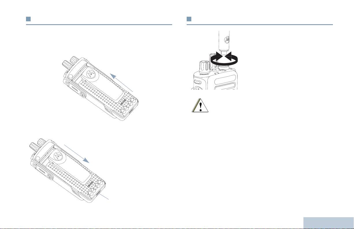
Bataryayı Takma
Anten Takma
Telsizinizi Kullanıma Hazırlama
Bataryayı, telsizin arkasındaki kızaklara hizalayarak uydurun.
Telsiz kapalıyken, anteni yuvasına
Bataryaya sıkıca bastırın ve mandalı yerine oturana dek yukarı
yerleştirin ve saat yönünde çevirin.
doğru kaydırın. Batarya mandalını kilitli pozisyonuna kaydırın.
Anteni çıkarırken, anteni saat
yönünün aksine çevirin.
Bataryayı
çıkarırken, telsizi
kapatın. Batarya
mandalını kilit açık
pozisyonuna
getirip orada tutun
ve bataryayı
aşağıya doğru
kaydırarak
kızaklarından alın.
3
Türkçe
Batarya
Mandalı
Antenin değiştirilmesi gerektiği durumlarda kesinlikle
sadece MOTOTRBO antenler kullanın. Bunu dikkate
almazsınız telsiziniz zarar görecektir.
İkaz

Kemer Kancası Takma
Üniversal Konektör Kapağını Takma
(Toz Kapağı)
Kanca yivlerini bataryanın
Üniversal konektör telsizinizde antenin olduğu tarafta yer
arkasında bulunanlara
almaktadır. Bu yuva MOTOTRBO aksesuarlarının telsize
uydurun ve bir klik sesi
bağlantısı için kullanılmaktadır.
duyana dek aşağı doğru
Kapağın çengelli ucunu,
bastırın.
üniversal konektörün
üzerindeki deliklerin içine
Kancayı çıkarırken, kemer
sokun. Alt taraftaki tırnak RF
kancasının tırnağına
konektörünün içine tam
bastırarak bataryadan ayırın.
olarak oturana dek kapağın
Bir anahtar kullanarak işinizi
üzerinden aşağı doğru
kolaylaştırabilirsiniz. Sonra
bastırın.
kancayı telsizden yukarı
Konektör kapağını telsize
kaydırarak çekerek alın.
sabitlemek için kelebek
vidayı saat yönünde çevirin.
Üniversal konektör kapağını çıkarırken, kapağın üzerine aşağı
doğru bastırın ve kelebek vidayı saat yönü aksine çevirin.
Üniversal konektörün kullanılmadığı durumlarda toz kapağını
takın.
Telsizinizi Kullanıma Hazırlama
4
Türkçe
Üniversal
Konektör
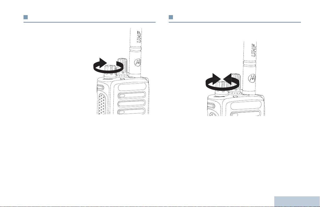
Telsizi Açma
Ses Ayarı
Telsizinizi Kullanıma Hazırlama
Aç/Kapa/Ses Ayarı
Sesi yükseltmek için, Aç/Kapa/Ses Ayar Topuzunu saat
Topuzunu bir klik sesi
yönünde çevirin.
duyana dek saat yönünde
döndürün. LED kesintisiz
yeşil yanar.
Açılma testinin başarılı
olduğunu gösteren kısa bir
ton sesi duyulur.
NOT: Eğer telsizin tonlar/
uyarılar işlevi devre
dışı bırakılmışsa,
açılırken ton sesi
duyulmaz (37.
sayfadaki Telsiz
Tonlarını/Uyarılarını
Açma ve Kapatma adlı bölüme bakın).
Sesi azaltırken de, bu topuzu aksi saat yönünde çevirin.
Eğer telsiziniz açılmıyorsa bataryasını kontrol edin. Bataryanın
NOT: Telsizinizi, ses seviyesinin önceki programlı minimum
şarj edilmiş olduğundan ve doğru takıldığından emin olun.
sese döndürülemediği durumlarda ses farkını minimum
Telsiziniz yine de açılmı
yorsa satıcınızla temas kurun.
düzeyde tutacak şekilde programlayabilirsiniz. Ayrıntılı
bilgi almak için satıcınızla ya da sistem yöneticinizle
Telsizi kapatırken, bu topuzu bir klik sesi duyana kadar aksi saat
görüşün.
yönünde çevirin.
5
Türkçe
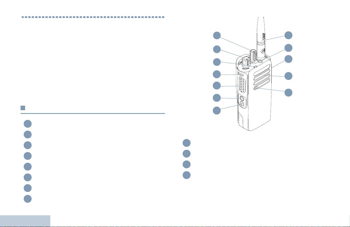
Telsiz Kumandaları nın Yerleri
Zaman ayırıp aşağıdakileri gözden geçirin:
Telsiz Kumandaları . . . . . . . . . . . . . . . . . . . . . . . . . . . 6. Sayfa
Programlanabilir Düğmeler . . . . . . . . . . . . . . . . . . . . . 7. Sayfa
Bas-Konuş (PTT) Düğmesi . . . . . . . . . . . . . . . . . . . . . 8. Sayfa
Geleneksel Analog Kip ile Dijital Kip Arasında
Seçim Yapma . . . . . . . . . . . . . . . . . . . . . . . . . . . . . 9. Sayfa
IP Saha Bağlantısı . . . . . . . . . . . . . . . . . . . . . . . . . . 10. Sayfa
Capacity Plus (Artı Kapasite) . . . . . . . . . . . . . . . . . . 10. Sayfa
Linked Capacity Plus (Bağlı Ek Kapasite). . . . . . . . . 11. Sayfa
Telsiz Kumandaları
Kanal Seçim Topuzu
Aç/Kapa (On/Off)/Ses Ayar Topuzu
LED Göstergesi
1. Yan Düğme*
Bas-Konuş (PTT) Düğmesi
2. Yan Düğme*
Telsiz Kumandalarının Yerleri
3. Yan Düğme*
Mikrofon
6
Türkçe
1
2
3
4
5
6
7
8
Hoparlör
Üniversal Aksesuar Konektörü
Acil Durum Düğmesi*
Anten
* Bu düğmeler programlanabilir.
1
12
2
11
10
3
4
9
5
8
6
7
9
10
11
12

Kanal için Sesli Duyuru – Mevcut kanalın bölge ve kanal sesli
Programlanabilir Düğmeler
duyuru mesajlarını çalar. Bu işlev, Sesli Duyuru devre dışı
bırakıldığında kullanılamaz.
Telsiz Kumandalarının Yerleri
Satıcınız programlanabilir düğmeleri, düğmelere basma
sürenize bağlı olarak ya telsizin işlevlerine ya da ön ayarlı
Acil Durum – Programlamaya bağlı olarak, acil durum alarmını
kanallara/gruplara tayin edilmiş kısa yollar olarak
ya da çağrısını başlatır ve iptal eder.
programlayabilir:
Akıllı Ses Açık/Kapalı – Akıllı Sesi açar ya da kapatır.
• Kısa basma – Seri şekilde basıp bırakın.
‡
• Uzun basma – Programlanan süre kadar baslı tutma.
Manuel Saha Gezinme*
– Manuel saha aramayı başlatır.
• Basılı tutma – Düğmeyi sürekli basılı tutma.
Mik OKK Açık/Kapalı – Dâhili mikrofonun otomatik kazanç
NOT: Düğmeleri basılı tutma için programlanan süreler, tayin
kontrolünü (OKK) açar ya da kapatır. Bluetooth'lu
edilebilir tüm telsiz/yazı lım özellikleri ve ayarları için
uygulamalarda kullanılamaz.
geçerlidir. Acil Durum düğmesinin süresinin
İzle – Seçili kanaldaki faaliyetleri izler.
programlanması hakkında ayrıntılı bilgi almak için 27.
sayfadaki Acil Durum İşlemi adlı bölüme bakın.
‡
İstenmeyen Kanalın Silinmesi*
– Tarama listesinden, Seçili
Kanal haricinde istenmeyen kanalları geçici olarak kaldırır.
Tayin Edilebilir Telsiz İşlevleri
Seçili Kanal, kullanıcı tarafından seçilen taramanın başlatıldığı
TM
bölge/kanal kombinasyonu demektir.
Bluetooth
Ses Anahtarı – Atanmış ses yolunu, ya telsizin
dâhili hoparlörüne ya da Bluetooth-etkin harici aksesuara verir.
Tek Tuşla Erişim – Doğrudan ön tanımlı bir Özel ya da
Bluetooth Bağlan – Bluetooth bul-ve-bağlan işlemlerini
Grup Çağrısını, Çağrı Uyarısını veya Hızlı Yazılı mesajı başlatır.
başlatır.
Opsiyon Kartı Özelliği – Opsiyon kartının etkin olduğu kanallar
Bluetooth Bağlantısını Kes – Terminates all existing Bluetooth
için opsiyon kartı özellik(ler)ini açar ya da kapatır.
connections between your radio and any Bluetooth-enabled
devices.
Çağrı Yönlendirme – Çağrı Yönlendirmeyi açıktan kapalıya,
kapalıdan açığa geçirir.
7
Türkçe
* Capacity Plus için geçerli değil
‡
Linked Capacity Plus için geçerli değil

‡
Sürekli İzleme*
– İşlev devre dışı bırakılana kadar seçili
Tayin Edilebilir Ayarlar ya da Uygulama Özellikleri
kanalın tüm telsiz trafiğini izler.
Tüm Tonlar/Uyarılar – Tüm tonları ve uyarıları açar ya da
Gizlilik – Gizliliği açar ya da kapar.
kapatır.
‡
Yineleyici/Talkaround*
– Yineleyici kullanılması ya da diğer
Güç Seviyesi – Güç seviyesini yüksekle alçak arasında seçer.
telsizle doğrudan iletişim kurulması arasında seçim yapar.
Susturucu – Susturucu seviyesini sıkı ve normal arasında
‡
Tarama*
– Taramayı açar ya da kapatır.
seçer.
Saha Kilidi Açık/Kapalı* – Otomatik saha gezinmeyi açar
ya da kapatır.
Bas-Konuş (PTT) Düğmesi
Telemetri Kontrol – Yerel ya da uzak telsiz üzerinde Çıkış
Pinini kontrol eder.
Telsizin kenarındaki Bas-
Konuş düğmesi iki temel
İletim Kesme Uzaktan Devre Dışı – Kanalı boşaltmak için
amaca hizmet eder:
sürmekte olan kesilebilir çağrıyı durdurur.
• Bas-Konuş düğmesi,
Sesli Duyuru Açık/Kapalı – Sesli Duyuruyu açar ya da kapatır.
çağrı yapılıyorken
telsizin çağrıdaki diğer
Eller Serbest Kullanım (VOX) – VOX'u açar ya da kapatır.
telsizlere iletimde
bulunmasına müsaade
Bölge – Bölgeler listesinden seçim yapılmasını sağlar.
eder.
Batarya Gücü – LED Göstergesi aracılığıyla bataryanın gücünü
Konuşmak için Bas-
gösterir.
Konuş düğmesini
basılı tutun. Dinlemek
Telsiz Kumandalarının Yerleri
için Bas-Konuş
düğmesini bırakın.
Bas-Konuş düğmesine basıldığında mikrofon etkin hale gelir.
8
Türkçe
* Capacity Plus için geçerli değil
‡
Linked Capacity Plus için geçerli değil
Bas-
Konuş
Düğmesi
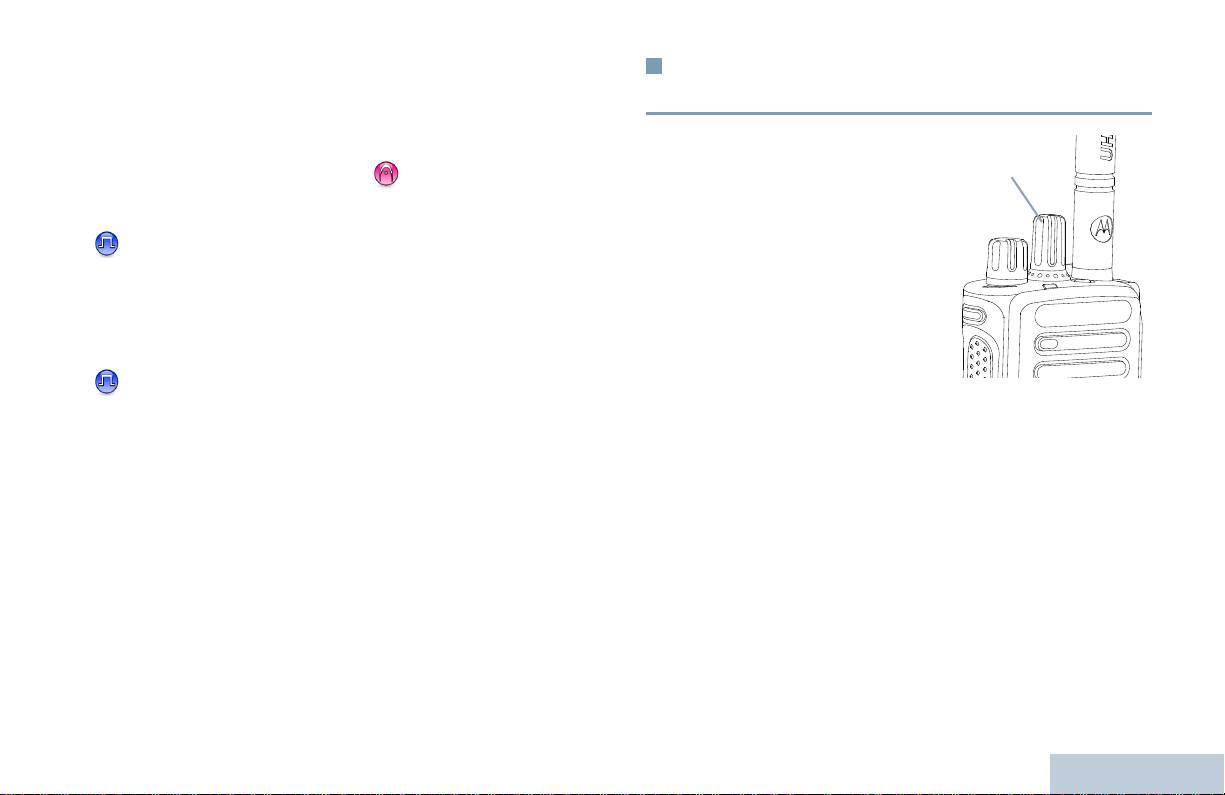
• Bas-Konuş düğmesi, çağrı yapılmazken yeni bir çağrı
Geleneksel Analog Kip ile Dijital Kip
yapmak için kullanılır (18. sayfada Telsiz Çağrısı Yapma adlı
Arasında Seçim Yapma
bölüme bakın).
Telsiz Kumandalarının Yerleri
Programlamaya bağlı olmak kaydıyla, eğer Konuşma İzni Tonu
Telsizinizdeki her kanal, ister
ya da Bas-Konuş (PTT) Yan Tonu etkinse, konuşmadan
geleneksel analog veya
önce, kısa uyarı tonu sona erene kadar bekleyin.
istenirse geleneksel dijital
kanal olarak
Çağrı esnasında, eğer telsiziniz üzerinde Kanal Boş
yapılandırılabilir. Analog ya
Gösterge özelliği (satıcınız tarafından programlanır)
da dijital kanal arasında
etkinse, hedef telsiz (çağrınızı alan telsiz) Bas-Konuş
seçim yapmak için Kanal
düğmesini bırakt
ığı anda kısa bir uyarı tonu duyarsınız. Bu
Seçim Topuzunu kullanın.
ton sesi kanalın yanıt vermeniz için boş olduğunu gösterir.
Dijitalden analog kipe
geçtiğinizde, bazı belirli
Telsizinizin Acil Durum Çağrısı alması gibi durumlarda
özellikler kullanılamaz.
görüşmeniz kesilecek ve PTT (bas-konuş) butonunu
Telsizinizin hem analog hem de dijital kipte çalışan özellikleri de
bırakmanız gerektiğini hatırlatan sürekli konuşma yasağı
vardır. Bununla birlikte, her bir özelliğin çalışmasındaki ufak
ton sesi duyulacaktır.
tefek farklılıklar telsizinizin performansını ETKİLEMEZ.
NOT: Telsiziniz çift kip tarama esnasında dijital ve analog
kipler arasında geçiş yapmaz (24. sayfadaki Tarama
adlı bölüme bakın).
9
Türkçe
Kanal Seçim Topuzu

Üyeler listesine manuel olarak kayıt ekleyemez ve silemezsiniz.
IP Saha Bağlantısı
Ayrıntılı bilgi almak için satıcınızla ya da sistem yöneticinizle
görüşün.
Bu özellik sayesinde telsizinizi, İnternet Protokolü (IP) ağı
aracılığıyla bağlı, farklı mevcut sahalara bağlayarak, tek bir
sahanın kapsama alanının ötesinde konvansiyonel
Capacity Plus (Artı Kapasite)
haberleşmede de kullanabilirsiniz.
Telsiz, kapsama sahasının dışına çıkıp başka birinin menziline
Capacity Plus, yüzlerce kullanıcıyı ve 254'e kadar Grubu
girdiğinde, çağrı/veri iletimlerini göndermek ve almak için yeni
desteklemek için bir kanal havuzu kullanan MOTOTRBO telsiz
sahanın yineleyicisine bağlanır. Ayarlarınıza bağlı olarak, bu
sistemi tek saha birleştirme konfigürasyonudur. Bu özellik,
işlem otomatik ya da manuel olarak gerçekleştirilir.
telsizinizin Yineleyici Kipteyken mevcut tüm programlı
kanallardan verimli bir şekilde yararlanmasına olanak sağlar.
Telsiziniz bunu otomatik olarak uygulamaya ayarlıysa, mevcut
sahanın sinyali zayıf olduğunda ya da telsiz mevcut sahada
Capacity Plus'da kullanılamayan özelliklerin simgeleri menüde
hiçbir sinyal tespit edemediğinde müsait sahaların tümünü tarar.
yer almaz. Capacity Plus'da kullanılamayan özelliklere
Daha sonra Alınan Sinyal Güç Göstergesi (RSSI) değeri en
programlanabilir düğmelere basarak ulaşmak istediğinizde
yüksek olan yineleyiciye kilitlenir.
olumsuz bildirim ton sesi duyarsınız.
Manuel saha aramada, telsiz, o an için menzilde olan gezinme
Telsiziniz ayrıca geleneksel dijital kip, IP Saha Bağlantısı,
listesindeki bir sonraki sahayı arar (ancak bu saha en güçlü
Capacity Plus ve Bağlı Capacity Plus'da mevcut olan özelliklere
sinyale sahip olmayabilir) ve o sahaya kilitlenir.
de sahiptir. Bununla birlikte, her bir özelliğin çalışmasındaki ufak
tefek farklılıklar telsizinizin performansını ETKİLEMEZ.
NOT: Her kanalda sadece ya Tarama ya da Gezinme
etkindir; her ikisi aynı anda etkin olamaz.
Sistem hakkında ayrıntılı bilgi almak için satıcınızla ya da
sistem yöneticinizle görüşün.
Bu özelliğin etkin olduğu kanallar belirli bir gezinme listesine
eklenebilir. Telsiz en iyi sahanın yerini saptamak için otomatik
gezinme işlemi esnasında gezinme listesinde kanal(lar) arar.
Telsiz Kumandalarının Yerleri
Bir gezinme listesi en fazla 16 kanalı (Seçili Kanal da dâhil)
destekler.
10
Türkçe

Bağlı Ek Kapasite özelliğinin etkin olduğu kanallar belirli bir
Linked Capacity Plus (Bağlı Ek
gezinme listesine eklenebilir. Telsiz en iyi sahanın yerini
Kapasite)
saptamak için otomatik gezinme işlemi sırasında bu kanalları
Telsiz Kumandalarının Yerleri
arar.
Bağlı Ek Kapasite, en iyi Capacity Plus ve IP Saha Bağlantısı
konfigürasyonlarını bir araya getiren, MOTOTRBO telsiz
NOT: Üyeler listesine manuel olarak kayıt ekleyemez ve
sisteminin çoklu-saha çoklu-kanal birleştirme
silemezsiniz. Ayrıntılı bilgi almak için satıcınızla ya da
konfigürasyonudur.
sistem yöneticinizle görüşün.
Bağlı Ek Kapasite özelliği olan telsizinizle, İnternet Protokolü
Aynı Ek Kapasite’de olduğu gibi, Bağlı Capacity Plus'da da
(IP) ağıyla bağlı farklı mevcut sahalara bağlanarak, ortak
kullanılamayan özelliklerin simgeleri menüde yer almaz.
kullanımlı haberleşmeyi tek bir saha kapsama alanının ötesinde
Programlanabilir düğmelere basarak Bağ
lı Ek Kapasite 'de
genişletebilirsiniz. Bağlı Ek Kapasite ayrıca, her mevcut saha
kullanılamayan özelliklere ulaşmak istediğinizde olumsuz
tarafından desteklenen kombine edilmiş kullanılabilir mevcut
bildirim ton sesi duyarsınız.
kanallardan yararlanarak kapasitede de artış sağlar.
Ayrıntılı bilgi almak için satıcınızla ya da sistem yöneticinizle
Telsiz, kapsama sahasının dışına çıkıp başka birinin menziline
görüşün.
girdiğinde, çağrı/veri iletimlerini göndermek ve almak için yeni
sahanın yineleyicisine ba
ğlanır. Ayarlarınıza bağlı olarak, bu
işlem otomatik ya da manuel olarak gerçekleştirilir.
Telsiziniz bunu otomatik olarak uygulamaya ayarlıysa, mevcut
sahanın sinyali zayıf olduğunda ya da telsiz mevcut sahada
hiçbir sinyal tespit edemediğinde müsait sahaların tümünü tarar.
Daha sonra Alınan Sinyal Güç Göstergesi (RSSI) değeri en
yüksek olan yineleyiciye kilitlenir.
Manuel saha aramada, telsiz, o an için menzilde olan gezinme
listesindeki bir sonraki sahayı arar (ancak bu saha en güçlü
sinyale sahip olmayabilir) ve o sahaya kilitlenir.
11
Türkçe

İki kez yanıp sönen yeş
il – Telsiz kişisel gizliliği olan bir çağrı
Durum Göstergelerinin Yerleri
ya da veri alıyordur .
Araliksiz sari – Telsiz konvansiyonel bir kanalı izliyordur. Ayrıca
Telsiziniz çalışma durumunu aşağıdakiler aracılığıyla gösterir:
Batarya Gücü düğmesine basıldığında kalan batarya şarjını da
LED Göstergesi. . . . . . . . . . . . . . . . . . . . . . . . . . . . . 12. Sayfa
gösterir.
Ses Tonları . . . . . . . . . . . . . . . . . . . . . . . . . . . . . . . . 13. Sayfa
Yanıp sönen sarı – Telsiz aktivite taraması yapıyordur ya da
Gösterge Tonları . . . . . . . . . . . . . . . . . . . . . . . . . . . . 13. Sayfa
Çağrı Uyarısı alıyordur veya tüm lokal Bağlı Ek Kapasite
kanalları meşguldür.
LED Göstergesi
İki kez yanıp sönen sarı – Telsiz, Capacity Plus ya da Bağlı
Capacity Plus kipindeyken artık yineleyiciye bağlanmaz; tüm Ek
LED göstergesi, telsizinizin
Kapasite kanalları ya da Bağlı Ek Kapasite kanalları o anda
çalışma durumunu gösterir.
me
şguldür, Oto-Roaming (Otomatik Dolaşım) etkindir, telsiz
Yanıp sönen kırmızı – Tels iz,
aktif olarak yeni bir saha arıyordur. Ayrıca, telsizin henüz bir
azalmış bataryayla iletimde
grup çağrı uyarısına yanıt vermediğini ya da telsizin kilitli
bulunuyordur, acil durum iletimi
olduğunu da gösterir.
alıyordur ya da açıldıktan
sonraki kendi kendine testte
hata vermiştir.
NOT: Geleneksel kipteyken, LED yeşil yanıp sönüyorsa, bu,
Aralıksız yeşil – Telsiz a çılıyor
telsizin yayında bir faaliyet tespit ettiğini gösterir. Dijital
ya da iletimde bulunuyordur.
protokolün özelliğine bağlı olmak kaydıyla, bu faaliyet
Ayrıca Batarya Gücü
telsizin programlı kanalını etkileyebilir de etkileyemez
düğmesine basıldığında
de.
yanıyorsa batarya şarjının tam
dolu olduğunu gösterir.
Capacity Plus’da, telsizin yayında olan faaliyet
aradığını gösteren herhangi bir LED göstergesi mevcut
Durum Göstergelerinin Yerleri
Yanip sönen yesil – Telsiz ya
değildir.
kişisel gizliliği olmayan bir çağrı
veya veri alıyordur ya da yayın
etkinliğini denetliyordur.
12
Türkçe
LED Göstergesi
Gösterge Tonları
Ses Tonları
Durum Göstergelerinin Yerleri
Uyarı tonları size, telsizin durumunun ya da telsizin alınan
Tiz ton sesi Pes ton sesi
veriye yanıtının işitilebilir göstergelerini sağlar.
Olumlu Gösterge Tonu
Sürekli Ton
Monoton bir sestir. Durdurulana kadar
sürekli ses verir.
Olumsuz Gösterge Tonu
Süreli Ton Telsizde yapılan süre ayarına bağlı
olarak süreli ses verir. Ton kendi
kendine başlar, durur ve tekrar eder.
Tekrarlı Ton Kullanıcı tarafından durdurulana kadar
kendi kendine tekrar eden tek bir
tondur.
Anlık Ton
Telsizde belirlenen kısa bir süre
boyunca yalnız bir kez ses verir.
13
Türkçe
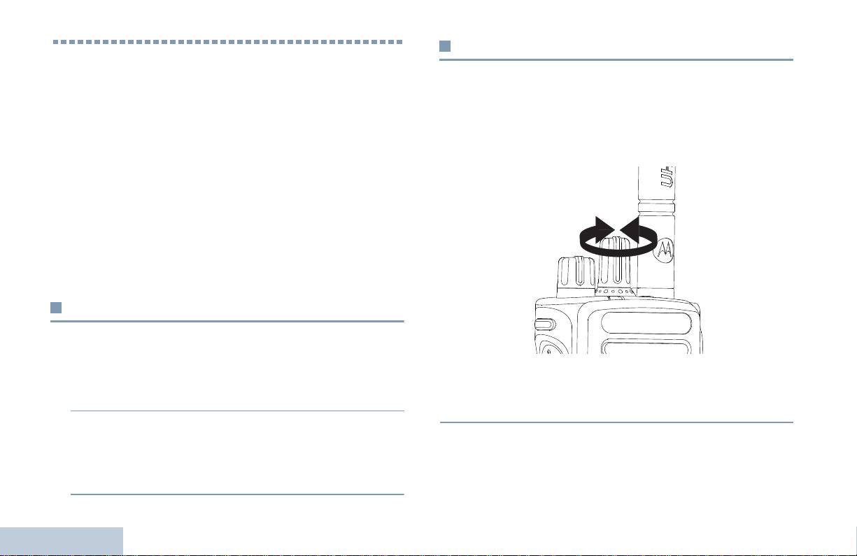
Kanal Seçimi
Çağrı Yapma ve Alma
İletimler bir kanal üzerinde gönderilir ve alınır. Telsizinizin
MOTOTRBO Seyyar Telsizinizin nasıl yapılandırıldığını
konfigürasyonuna (yapılandırmasına) bağlı olarak, her kanal,
anladıktan sonra, artık telsizinizi kullanmaya hazırsınız.
farklı kullanıcı gruplarını destekleyecek biçimde farklı farklı
Temel Çağrı özelliklerine kendinizi alıştırmanız için bu gezinme
programlanabilir ya da her kanala farklı özellikler yüklenebilir.
kılavuzunu kullanın:
İstenilen bölgeyi seçtikten sonra, iletim göndermek ya da almak
Bölge Seçimi . . . . . . . . . . . . . . . . . . . . . . . . . . . . . . . 14. Sayfa
istediğiniz kanalı seçin.
Kanal Seçimi . . . . . . . . . . . . . . . . . . . . . . . . . . . . . . . 14. Sayfa
Telsiz Çağrısı Alma ve Buna Yanıt Verme. . . . . . . . . 15. Sayfa
Telsiz Çağrısı Yapma . . . . . . . . . . . . . . . . . . . . . . . . 18. Sayfa
Telsiz Çağrısını Durdurma. . . . . . . . . . . . . . . . . . . . . 21. Sayfa
Talkaround . . . . . . . . . . . . . . . . . . . . . . . . . . . . . . . . 21. Sayfa
İzleme Özellikleri. . . . . . . . . . . . . . . . . . . . . . . . . . . . 22. Sayfa
Bölge Seçimi
Telsiziniz 32 adete kadar kanal ve her birinde en fazla 16 kanal
olmak üzere 2 adede kadar bölge destekler.
Prosedür:
Prosedür:
Kanal Seçim Topuzunu döndürerek aktif grup adına ya da
1 Programlanmış Bölge düğmesine basın.
ID'sine sahip kanalı seçin.
2 Telsizin 1. Bölgeden 2. Bölgeye geçtiğini belirten pozitif
(olumlu) sinyal ton sesi duyarsınız.
Çağrı Yapma ve Alma
YA DA
Telsizin 2. Bölgeden 1. Bölgeye geçtiğini belirten negatif
(olumsuz) sinyal ton sesi duyarsınız.
14
Türkçe
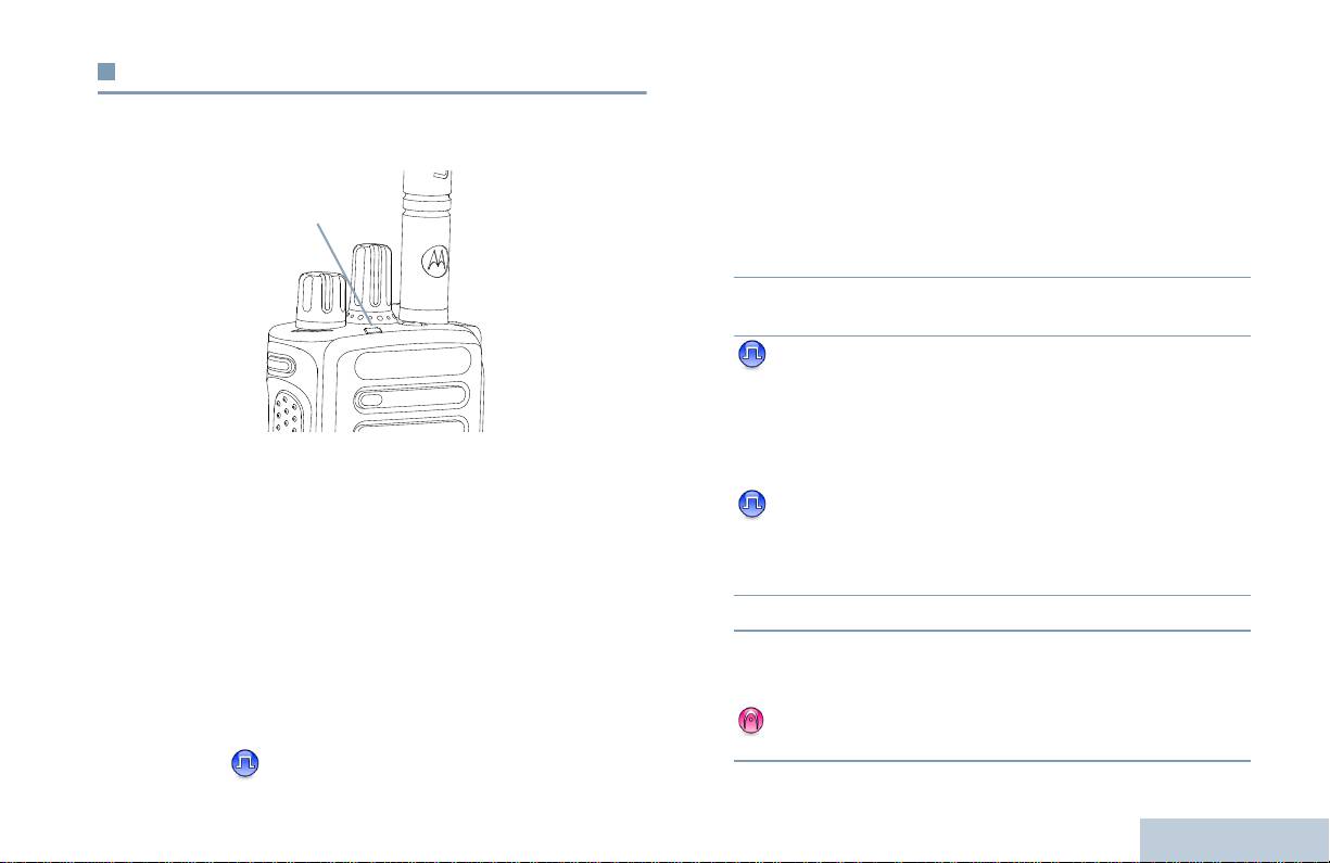
Telsiz Çağrısı Alma ve Buna Yanıt Verme
Grup Çağrısı Alma ve Buna Yanıt Verme
Bir kullanıcı grubundan çağrı almak için telsiziniz bu grubun bir
Çağrı Yapma ve Alma
Kanal, abone ID'si ya da grup ID'si ekranda göründükten sonra,
parçası olarak düzenlenmelidir.
çağrı almaya ve bunlara yanıt vermeye geçebilirsiniz.
Prosedür:
1 LED ışığı yeşil yanıp sönmeye başlar. Telsiz yeniden sesli
kipe döner ve gelen aramalar telsizin hoparlöründen
duyulur.
2 Bu çağrıya yanıt vermek için telsizinizi dik olarak ağzınızdan
1 – 2 inç (2,5 – 5 cm) uzakta tutunuz.
3 Eğer Kanal Boş Gösterge özelliği etkinse, iletimde
bulunan telsizin Bas-Konuş (PTT) düğmesi serbest
bırakıldığı anda kısa bir uyarı sesi duyarsınız. Bu ses,
kanalın serbest olduğunu, yanıt verebileceğinizi gösterir.
Telsiz iletimde bulunuyorken LED aralıksız yeşil yanar ve telsiz
Çağrıya yanıt vermek için Bas-Konuş düğmesine basın.
iletim alıyorken de yeşil yanıp söner.
YA DA
Eğer Ses Kesintisi özelliği etkinse, iletim telsizinden
NOT: Telsiz iletimde bulunuyorken LED aralıksız yeşil yanar
gelen o anki çağrıyı durdurmak ve kanalı sizin
ve telsiz gizlilik-etkin çağrı alıyorken de çift yeşil yanıp
konuşmanıza/yanıtınıza ayırmak amacıyla boşaltmak için
söner.
Bas-Konuş düğmesine basın.
Gizlilik etkin çağrıyı çözebilmesi için telsiziniz, iletimde
4 LED kesintisiz yeşil yanmaya başlar.
bulunan telsizle (çağrıyı aldığınız telsiz) aynı Gizlilik
5 Konuşma İzni Tonunun bitmesini bekleyin (eğer etkinse) ve
Tuşuna YA DA Tuş Değerine ve Tuş ID'sine (satıcınız
mikrofona doğru anlaşılır biçimde konuşun.
tarafından programlanan) sahip olmalıdır.
YA DA
Bas-Konuş Yan Tonunun bitmesini bekleyin (eğer
Ayrıntılı bilgi için 31. sayfadaki Gizlilik adlı bölüme
etkinse) ve mikrofona doğru anlaşılır biçimde konuşun.
bakın.
15
Türkçe
LED Göstergesi

6 Dinlemek için Bas-Konuş düğmesini bırakın.
4 Çağrıya yanıt vermek için Bas-Konuş düğmesine basın.
LED kesintisiz yeşil yanmaya başlar.
7 Önceden belirlenen süre boyunca hiçbir ses etkinliği
olmazsa, çağrı sona erer.
5 Konuşma İzni Tonunun bitmesini bekleyin (eğer etkinse) ve
mikrofona doğru anlaşılır biçimde konuşun.
Grup Çağrısı yapmakla ilgili ayrıntılı bilgi için 18. sayfadaki
6 Dinlemek için Bas-Konuş düğmesini bırakın.
Grup Çağrısı Yapma adlı bölüme bakın.
7 Önceden belirlenen süre boyunca hiçbir ses etkinliği
olmazsa, çağrı sona erer.
Özel Çağrı Alma ve Buna Yanıt Verme
8 Kısa bir ton sesi duyarsınız.
Bireysel bir telsizle başka bir bireysel telsiz arasında yapılan
çağrılara Özel Çağrı denir.
Özel Çağrı yapmakla ilgili ayrıntılı bilgi için 19. sayfadaki
Özel Çağrı Yapma adlı bölüme bakın.
Prosedür:
Özel Çağrı aldığınızda:
1 LED ışığı yeşil yanıp sönmeye başlar. Telsiz yeniden sesli
kipe döner ve gelen aramalar telsizin hoparlöründen
duyulur.
2 Bu çağrıya yanıt vermek için telsizinizi dik olarak ağzınızdan
1 – 2 inç (2,5 – 5 cm) uzakta tutunuz.
3 Eğer Kanal Boş Gösterge özelliği etkinse, iletimde bulunan
telsizin Bas-Konuş (PTT) düğmesi serbest bırakıldığı anda
kısa bir uyarı sesi duyarsınız. Bu ses, kanalın serbest
olduğunu, yanıt verebileceğinizi gösterir.
YA DA
Eğer Ses Kesintisi özelliği etkinse, iletim telsizinden gelen o
Çağrı Yapma ve Alma
anki çağrıyı durdurmak ve kanalı sizin konuşmanıza/
yanıtınıza ayırmak amacıyla boşaltmak için Bas-Konuş
düğmesine basın.
16
Türkçe

Herkese Çağrıları Alma
Seçici Çağrı Alma ve Buna Yanıt Verme
Herkese çağrı, tek bir telsizden kanaldaki tüm telsizlere yapılan
Tek bir telsizden başka tek bir telsize yapılan çağrılara Seçici
Çağrı Yapma ve Alma
çağrıdır. Tüm kullanıcıların duyması gereken önemli duyuruların
Çağrı denir. Bu, analog sistem üzerinde gerçekleştirilen Özel
yapılması için kullanılır.
Çağrıdır.
Prosedür:
Prosedür:
Herkese Çağrı aldığınızda:
Seçici Çağrı aldığınızda:
1 Bir ton sesi duyulur ve LED ı şığı yeşil yanıp sönmeye başlar.
1 LED ışığı yeşil yanıp sönmeye başlar.
Telsiz yeniden sesli kipe döner ve gelen aramalar telsizin
2 Telsizi dikey olarak ağzınızdan 1 – 2 inç (2,5 – 5 cm) uzakta
hoparlöründen duyulur.
tutun. Telsiz yeniden sesli kipe döner ve gelen aramalar
2 Önceden belirlenen süre boyunca hiçbir ses etkinliği
telsizin hoparlöründen duyulur.
olmazsa, Herkese Çağrı sona erer. Herkese Çağrı, sona
3 Eğer Kanal Boş Gösterge özelliği etkinse, iletimde bulunan
ermek için önceden belirlenen süre kadar beklemez.
telsizin Bas-Konuş (PTT) düğmesi serbest bırakıldığı anda
Eğer Kanal Boş Gösterge özelliği etkinse, iletimde
kısa bir uyarı sesi duyarsınız. Bu ses, kanalın serbest
bulunan telsizin Bas-Konuş (PTT) düğmesi serbest
olduğunu, yanıt verebileceğinizi gösterir.
bırakıldığı anda kısa bir uyarı sesi duyarsınız. Bu ses,
4 Çağrıya yanıt vermek için Bas-Konuş düğmesine basın.
kanalın artık kullanıma müsait olduğunu gösterir.
LED kesintisiz yeşil yanmaya başlar.
Herkese Çağrıya yanıt veremezsiniz.
5 Konuşma İzni Tonunun bitmesini bekleyin (eğer etkinse) ve
mikrofona doğru anlaşılır biçimde konuşun.
NOT: Çağrı alınırken farklı bir kanala geçmeniz halinde telsiz
6 Dinlemek için Bas-Konuş düğmesini bırakın.
Herkese Çağrıyı almayı durdurur.
Herkese Çağrı yapılıyorken, çağrı sonlanana dek
7 Önceden belirlenen süre boyunca hiçbir ses etkinliği
programlı düğme işlevlerinin hiçbirisini
olmazsa, çağrı sona erer.
kullanamazsınız.
8 Kısa bir ton sesi duyarsınız.
Özel Çağrı yapmakla ilgili ayrıntılı bilgi için 19. sayfadaki Seçici
Çağrı Yapma adlı bölüme bakın.
17
Türkçe
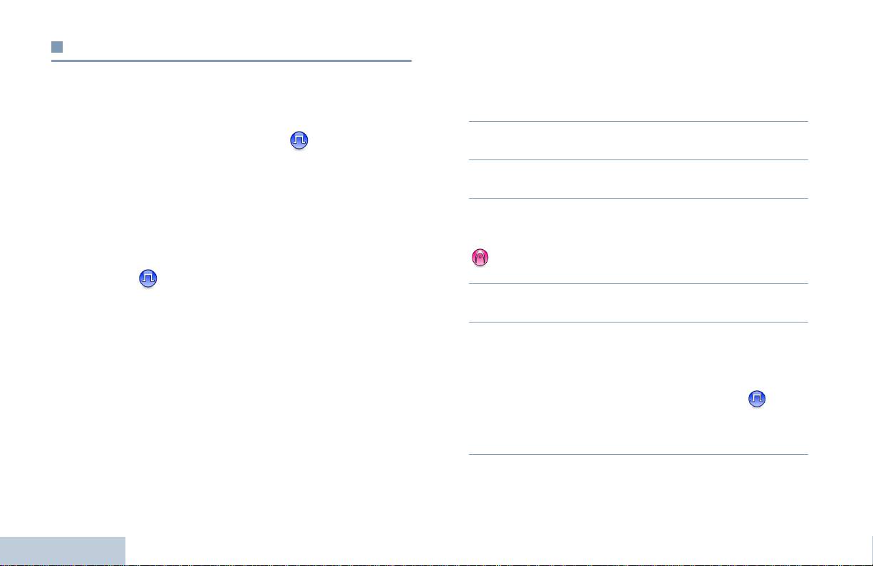
Prosedür:
Telsiz Çağrısı Yapma
1 Aktif grup adına ya da ID'sine sahip kanalı seçin. 14.
Kanalınızı seçtikten sonra, abone adı ya da ID'sini veya grup
sayfadaki Kanal Seçimi adlı bölüme bakın.
adı ya da ID'sini şunları kullanarak seçebilirsiniz:
YA DA
Programlanmış Tek Tuş Erişim düğmesine basın.
• Kanal Seçim Topuzu
2 Telsizi dikey olarak ağzınızdan 1 – 2 inç (2,5 – 5 cm) uzakta
• Programlı Tek Tuşla Erişim düğmeleri
tutun.
NOT: Gizlilik-etkin iletimde bulunabilmeniz için telsizinizin
3 Çağrı yapmak için Bas-Konuş düğmesine basın. LED
kanal üzerindeki Gizlilik özelliği etkin olmalıdır. Sadece
kesintisiz yeşil yanmaya başlar.
sizin telsizinizle aynı Gizlilik Tuşu YA DA aynı Tuş
4 Konuşma İzni Tonunun bitmesini bekleyin (eğer etkinse) ve
Değeri ve Tuş ID’si olan hedef telsizler iletileri
mikrofona doğru anlaşılır biçimde konuşun.
çözebilecektir.
YA DA
Bas-Konuş Yan Tonunun bitmesini bekleyin (eğer
Ayrıntılı bilgi için 31. sayfadaki Gizlilik adlı bölüme
etkinse) ve mikrofona doğru anlaşılır biçimde konuşun.
bakın.
5 Dinlemek için Bas-Konuş düğmesini bırakın. Hedef telsiz
Tek Tuş Erişim özelliği sayesinde, önceden tanımlı
yanıt verirken LED yeşil yanıp söner.
ID'ye kolaylıkla Grup ya da Özel Çağrı yapabilirsiniz.
6 Eğer Kanal Boş Gösterge özelliği etkinse, hedef telsizin
Bu özellik, kısa ya da uzun basmalı olarak düğmelere
Bas-Konuş (PTT) düğmesi serbest bırakıldığı anda kısa bir
tayin edilebilir. Bir adet Tek Tuş Erişim düğmesine
uyarı sesi duyarsınız. Bu ses, kanalın serbest olduğunu,
SADECE bir adet ID tayin edebilirsiniz. Telsizinizde
yanıt verebileceğinizi gösterir.
birden fazla düğmeyi Tek Tuş Erişim düğmesi olarak
Yanıt vermek için Bas-Konuş düğmesine basın.
programlayabilirsiniz.
YA DA
Önceden belirlenen süre boyunca hiçbir ses etkinliği
Kanal Seçim Topuzuyla Çağrı Yapma
olmazsa, çağrı sona erer.
Çağrı Yapma ve Alma
Grup Çağrısı Yapma
Bir kullanıcı grubuna çağrı göndermek için telsiziniz bu grubun
bir parçası olarak düzenlenmelidir.
18
Türkçe

3 Çağrı yapmak için Bas-Konuş düğmesine basın. LED
Özel Çağrı Yapma
kesintisiz yeşil yanmaya başlar.
Yetkili bir kişisel telsizden başlatılan Özel Çağrıyı almak
Çağrı Yapma ve Alma
4 Konuşma İzni Tonunun bitmesini bekleyin (eğer etkinse) ve
ve/ya da bu çağrıya yanıt vermek için, telsizinizin sizin
mikrofona doğru anlaşılır biçimde konuşun.
için Özel Çağrı başlatmaya programlanmış olması
lazımdır.
5 Dinlemek için Bas-Konuş düğmesini bırakın. Hedef telsiz
yanıt verirken LED yeşil yanıp söner.
İki tür Özel Çağrı mevcuttur. Birinci türde çağrı kurulmadan
önce yayında telsiz olup olmadığı kontrol edilir; ikinci türde ise
6 Eğer Kanal Boş Gösterge özelliği etkinse, hedef telsizin
çağrı derhal kurulur.
Bas-Konuş (PTT) düğmesi serbest bırakıldığı anda kısa bir
uyarı sesi duyarsınız. Bu ses, kanalın serbest olduğunu,
Bu çağrı türlerinden sadece birisi satıcınız tarafından telsizinize
yanıt verebileceğinizi gösterir.
programlanabilir.
Yanıt vermek için Bas-Konuş düğmesine basın.
Eğer bu özellik etkin değilse, Tek Tuş Erişim düğmesi ya da
YA DA
Kanal Seçim Topuzu düğmeleri aracılığıyla Özel Çağrı
Önceden belirlenen süre boyunca hiçbir ses etkinliği
yaptığınızda olumsuz bildirim ton sesi duyarsınız.
olmazsa, çağrı sona erer.
Tek bir telsizle temas kurmak için Hızlı Yazılı Mesaj ya da Çağrı
7 Kısa bir ton sesi duyarsınız.
Uyarısı özelliklerini kullanın. Ayrıntılı bilgi için 30. sayfadaki
Yazılı Mesaj Özellikleri ya da 26. sayfadaki Çağrı Uyarısı
Seçici Çağrı Yapma
İşlemi adlı bölümlere bakın.
Aynı Özel Çağrı'da olduğu gibi, yetkili bir kişisel telsizden
Prosedür:
başlatılan Seçici Çağrıyı alabilmek ve/ya da bu çağrıya yanıt
verebilmek için, telsizinizin sizin için Özel Çağrı başlatmaya
1 Aktif grup adına ya da ID'sine sahip kanalı seçin. 14.
sayfadaki Kanal Seçimi adlı bölüme bakın.
programlanmış olması lazımdır.
YA DA
Prosedür:
Programlanmış Tek Tuş Erişim düğmesine basın.
1 Aktif grup adına ya da ID'sine sahip kanalı seçin. 14.
2 Telsizi dikey olarak ağzınızdan 1 – 2 inç (2,5 – 5 cm) uzakta
sayfadaki Kanal Seçimi adlı bölüme bakın.
tutun.
2 Telsizi dikey olarak ağzınızdan 1 – 2 inç (2,5 – 5 cm) uzakta
tutun.
19
Türkçe

3 Çağrı yapmak için Bas-Konuş düğmesine basın. LED
3 Çağrı yapmak için Bas-Konuş düğmesine basın. LED
kesintisiz yeşil yanmaya başlar.
kesintisiz yeşil yanmaya başlar.
4 Konuşma İzni Tonunun bitmesini bekleyin (eğer etkinse) ve
4 Konuşma İzni Tonunun bitmesini bekleyin (eğer etkinse) ve
mikrofona doğru anlaşılır biçimde konuşun.
mikrofona doğru anlaşılır biçimde konuşun.
YA DA
5 Dinlemek için Bas-Konuş düğmesini bırakın. Hedef telsiz
Bas-Konuş Yan Tonunun bitmesini bekleyin (eğer
yanıt verirken LED yeşil yanıp söner.
etkinse) ve mikrofona doğru anlaşılır biçimde konuşun.
6 Eğer Kanal Boş Gösterge özelliği etkinse, hedef telsizin
Bas-Konuş (PTT) düğmesi serbest bırakıldığı anda kısa bir
Kanaldaki kullanıcılar Herkese Çağrıya yanıt veremezler.
uyarı sesi duyarsınız. Bu ses, kanalın serbest olduğunu,
yanıt verebileceğinizi gösterir.
Yanıt vermek için Bas-Konuş düğmesine basın.
YA DA
Önceden belirlenen süre boyunca hiçbir ses etkinliği
olmazsa, çağrı sona erer.
7 Kısa bir ton sesi duyarsınız.
Herkese Çağrı yapma
Bu özellik size kanal üzerinde bulunan tüm kullanıcılara iletimde
bulunma olanağı tanır. Telsiziniz, bu özelliği kullanabileceğiniz
şekilde programlanmış olmalıdır.
Prosedür:
1 Aktif grup adına ya da ID'sine sahip kanalı seçin. 14.
sayfadaki Kanal Seçimi adlı bölüme bakın.
Çağrı Yapma ve Alma
2 Telsizi dikey olarak ağzınızdan 1 – 2 inç (2,5 – 5 cm) uzakta
tutun.
20
Türkçe

Talkaround
Telsiz Çağrısını Durdurma
Çağrı Yapma ve Alma
Yineleyicinizin çalışmadığı ya da yineleyicinin kapsama alanı
Bu özellik sayesinde, kanalı iletim için boşaltmak amacıyla
dışında, ancak diğer telsizlerin konuşma kapsamında
sürmekte olan Grup ya da Özel Çağrıyı durdurabilirsiniz.
olduğunuz anlarda da haberleşmeye devam edebilirsiniz.
Örneğin, kullanıcının haberi olmadan kazayla Bas-Konuş
Buna "talkaround" denmektedir.
düğmesinin basılı kaldığı telsiz mandalının "takılı kalması"
durumlarında bu özellik işe yarar.
NOT: Bu özellik Ek Kapasite ve Bağlı Ek Kapasite’da geçerli
Telsiziniz, bu özelliği kullanabileceğiniz şekilde programlanmış
değildir.
olmalıdır.
Prosedür:
Prosedür:
1 Programlanmış Yineleyici/Talkaround düğmesine basın.
İstenen kanal üzerindeyken;
2 Telsizin Talkaround kipinde olduğunu gösteren olumlu
1 Programlı İletim Kesme Uzaktan Devre Dışı düğmesine
bildirim ton sesi duyarsınız.
basın.
YA DA
2 Onay için bekleyin.
Telsizin Yineleyici kipinde olduğunu gösteren olumsuz
bildirim ton sesi duyarsınız.
3 Telsiz, kanalın artık boş olduğunu gösteren olumlu bildirim
ton sesi çıkarır.
Talkaround ayarı telsiz kapatıldıktan sonra da aynen kalır.
YA DA
Telsiz, kanalı boşaltamadığını bildiren olumsuz bildirim ton
sesi çıkarır.
Telsiziniz, eğer bu özellikle durdurulan kesilebilir bir çağrı
iletiyorsa, siz Bas-Konuş (PTT) düğmesini bırakana kadar
olumsuz bildirim ton sesi çıkarır. Kesilen telsiz ekranlı ise,
ekranında Çağrı Kesildi yazısı görünür.
21
Türkçe

İzleme Özellikleri
Devamlı İzleme
Seçili kanalın faaliyetlerini sürekli izlemek için Devamlı İzleme
Bir Kanal İzleme
özelliğini kullanın.
İletimde bulunmadan önce kanalın temiz olduğundan emin
NOT: Bu özellik Ek Kapasite ve Bağlı Ek Kapasite’da geçerli
olmak için İzleme özelliğini kullanın.
değildir.
NOT: Bu özellik Ek Kapasite ve Bağlı Ek Kapasite’da geçerli
Prosedür:
değildir.
1 Programlı Sürekli İzleme düğmesine basın.
Prosedür:
2 Telsiz bir uyarı ton sesi çıkarır, LED ışığı kesintisiz sarı
yanar.
1 Programlı İzleme düğmesini basılı tutun ve faaliyetleri
dinleyin.
3 Telsizi devamlı İzleme kipinden çıkarmak için
programlanmış Sürekli İzleme düğmesine basın.
2 Telsinizin nasıl programlandığına bağlı olarak ya telsiz
4 Telsiz uyarı ton sesi çıkarır ve LED ışığı kapanır.
faaliyeti ya da tamamen sessizlik duyarsınız.
3 "Beyaz ses” duyduğunuzda (kanalın boş olduğunu gösterir),
konuşmak için Bas-Konuş düğmesine basın ve dinlemek
için bu düğmeyi bırakın. LED kesintisiz sarı yanar.
Çağrı Yapma ve Alma
22
Türkçe

Tarama Listeleri
İleri Düzey Özellikler
İleri Düzey Özellikler
Tek tek kanallara/gruplara tarama listeleri oluşturulur ve tayin
Telsizinizin mevcut olan ileri düzey özellikleri hakkında daha
edilir. Telsiziniz, mevcut kanalın/grubun tarama listesinde
ayrıntılı bilgi almak için bu gezinme kılavuzunu kullanın:
belirtilen kanal/grup sırasına göre dönerek ses faaliyetlerini
Tarama Listeleri . . . . . . . . . . . . . . . . . . . . . . . . . . . . . 23. Sayfa
tarar.
Tarama . . . . . . . . . . . . . . . . . . . . . . . . . . . . . . . . . . . 24. Sayfa
Telsiziniz, her bir listede en fazla 16 üye olması kaydıyla, 250
Çağrı Bildirim Ayarları . . . . . . . . . . . . . . . . . . . . . . . . 26. Sayfa
adede kadar tarama listesini destekler. Her tarama listesi, hem
Çağrı Uyarısı İşlemi. . . . . . . . . . . . . . . . . . . . . . . . . . 26. Sayfa
analog hem de dijital girişlerden oluşan karışımları destekler.
Acil Durum İşlemi. . . . . . . . . . . . . . . . . . . . . . . . . . . . 27. Sayfa
NOT: Bu özellik Ek Kapasite ve Bağlı Ek Kapasite’da geçerli
Yazılı Mesaj Özellikleri. . . . . . . . . . . . . . . . . . . . . . . . 30. Sayfa
değildir.
Gizlilik . . . . . . . . . . . . . . . . . . . . . . . . . . . . . . . . . . . . 31. Sayfa
Çoklu-Saha Kontrolleri. . . . . . . . . . . . . . . . . . . . . . . . 32. Sayfa
Yalnız Çalışan . . . . . . . . . . . . . . . . . . . . . . . . . . . . . . 33. Sayfa
Şifre Kilitleme Özellikleri . . . . . . . . . . . . . . . . . . . . . . 33. Sayfa
Bluetooth . . . . . . . . . . . . . . . . . . . . . . . . . . . . . . . . . . 34. Sayfa
Uygulamalar . . . . . . . . . . . . . . . . . . . . . . . . . . . . . . . 36. Sayfa
23
Türkçe

Tarama
Taramayı Başlatma ve Durdurma
Prosedür:
Tarama başlattığınızda telsiziniz, ses faaliyeti olup olmadığına
bakmak için mevcut kanalın programlı tarama listesini sırayla
1 Programlanmış Tarama düğmesine basın.
gezerek devir yapar.
YA DA
Kanal Seçim Topuzunu kullanarak Otomatik Tarama etkin
LED ışığı sarı yanıp sönmeye başlar.
olan bir kanal seçin.
Çift kip tarama yapılırken bir dijital kanal üzerindeyseniz ve
2 Tarama etkin olduğunda sarı LED yanıp söner ve olumlu
telsiziniz bir analog kanal üzerine kilitlenmişse, çağrı sürdüğü
bildirim ton sesi duyarsınız.
sürece otomatik olarak dijital kipten analog kipe geçer. Bunun
YA DA
tersi de doğrudur.
Tarama devre dışı olduğunda LED söner ve olumsuz bildirim
İki tür tarama mevcuttur:
ton sesi duyarsınız.
• Ana Kanal Taraması (Manuel): Telsiziniz tarama listenizdeki
tüm kanalları/grupları tarar. Telsiziniz taramaya geçtiğinde -
Tarama Yapılırken İletime Yanıt Verme
ayarlarına bağlı olarak - otomatik olarak son taranmış "aktif"
Tarama esnasında telsiziniz faaliyet tespit edilen kanal/grup
kanal/gruptan ya da taramanın başlatılmış olduğu kanaldan
üzerinde durur. Telsiz bu kanal üzerinde, "kalma süresi" olarak
taramaya başlar.
bilinen programlanmış süre kadar kalır.
• Oto-Tarama (Otomatik): Telsiziniz, Oto-Tarama etkin bir
Prosedür:
kanal/grup seçtiğinizde otomatik olarak taramaya başlar.
1 Telsizi dikey olarak ağzınızdan 1 – 2 inç (2,5 – 5 cm) uzakta
NOT: Bu özellik Ek Kapasite ve Bağlı Ek Kapasite’da geçerli
tutun.
değildir.
Eğer Kanal Boş Gösterge özelliği etkinse, iletimde
bulunan telsizin Bas-Konuş (PTT) düğmesi serbest
bırakıldığı anda kısa bir uyarı sesi duyarsınız. Bu ses,
İleri Düzey Özellikler
kanalın serbest olduğunu, yanıt verebileceğinizi gösterir.
24
Türkçe

2 Kalma süresi boyunca Bas-Konuş düğmesini basılı tutun.
İstenmeyen Kanalı Yeniden Yükleme
LED kesintisiz yeşil yanmaya başlar.
Prosedür:
İleri Düzey Özellikler
3 Konuşma İzni Tonunun bitmesini bekleyin (eğer etkinse) ve
Silinmiş, istenmeyen kanalı yeniden yüklemek için
mikrofona doğru anlaşılır biçimde konuşun.
aşağıdakilerden birisini yapın:
YA DA
• Telsizi kapatın ve sonra yeniden açın YA DA
Bas-Konuş Yan Tonunun bitmesini bekleyin (eğer
• Programlanmış Tarama düğmesi aracılığıyla taramayı
etkinse) ve mikrofona doğru anlaşılır biçimde konuşun.
durdurun ve yeniden başlatın, YA DA
4 Dinlemek için Bas-Konuş düğmesini bırakın.
• Kanal Seçim Topuzuyla kanalı değiştirin.
5 Kalma süresi içinde yanıt vermezseniz, telsiz diğer kanalları/
grupları taramaya döner.
Oylamalı Tarama
İstenmeyen Kanalı Silme
Oylamalı Tarama size, farklı analog kanalları üzerinde aynı
Sürekli olarak istenmeyen çağrılar ya da gürültü (istenmeyen -
bilgileri ileten birden fazla baz istasyonu olan alanlarda geniş
"nuisance" - sözcüğü bu kavramdan üretilmiştir) üreten kanalları
kapsama alanı sağlar.
geçici olarak istenemeyen kanal yaparak silebilirsiniz.
Telsiziniz birden fazla baz istasyonunun analog kanallarını tarar
Bu özellik Seçili Kanal olarak tayin edilmiş kanallar için geçerli
ve alınan en güçlü sinyali seçmek için bir oylama işlemi
değildir.
gerçekleştirir. Bu bittikten sonra telsiziniz o baz istasyonundan
gelen iletilere sesini açar.
Prosedür:
Oylamalı Tarama işlemi sırasında sarı LED yanıp söner.
1 Telsiziniz istenmeyen ya da gürültü üreten bir kanal "üzerine
kilitlendiğinde", bir ton sesi duyana kadar programlı
Oylamalı tarama esnasında iletimlere yanıt vermek için, 24.
İstenmeyen Kanalı Sil düğmesine basın.
sayfada yer alan Tarama Yapılırken İletime Yanıt Verme adlı
bölümdeki işlemlerin aynısını uygulayın.
2 İstenmeyen Kanalı Sil düğmesini bırakın. İstenmeyen
kanal silinir.
25
Türkçe
Çağrı Bildirim Ayarları
2 Özel Çağrıya yanıt vermek için, Çağrı Uyarısı araması
alındıktan sonra dört (4) saniye içinde Bas-Konuş
Alınan Özel Çağrılar için zil seslerini açıp kapatabilirsiniz (37.
düğmesine basın.
sayfadaki Telsiz Tonlarını/Uyarılarını Açma ve Kapatma adlı
bölüme bakın).
Tek Tuş Erişim Düğmesiyle Çağrı Uyarısı
Yapma
Alarm Tonunun Sesini Açma
Prosedür:
Telsiziniz satıcınız tarafından, yanıtsız kalan telsiz çağrıları
1 Önceden belirlenmiş ID’lere Çağrı Uyarısı yapmak için
olduğunda sizi sürekli uyaracak şekilde programlanabilir. Bu
programlı Tek Tuş Erişim düğmesine basın.
uyarı, belirli aralıklarla alarm tonu sesinin yükselmesiyle
otomatik gerçekleşir.
2 Telsiziniz Çağrı Uyarısı gönderirken yeşil LED yanar.
Bu özelliğe Kademeli Uyarı (Kdml-uyarı) denir.
3 Çağrı Uyarısı onayı alınırsa, iki cırıltı sesi duyulur.
YA DA
Çağrı Uyarısı onayı alınmazsa, alçak ton sesi duyulur.
Çağrı Uyarısı İşlemi
Çağrı Uyarı gönderme sistemi sayesinde, belirli bir telsizi müsait
olduğunda sizi geri araması için uyarabilirsiniz. Bu özelliğe
programlı Tek Tuş Erişim düğmesiyle ulaşılabilir.
Çağrı Uyarısı Alma ve Buna Yanıt Verme
Prosedür:
Çağrı Uyarı araması aldığınızda;
1 Kısa bir tekrarlı ton sesi duyarsınız. Sarı LED ışığı yanıp
İleri Düzey Özellikler
söner.
26
Türkçe

Buna ek olarak her alarmın üç türü bulunmaktadır:
Acil Durum İşlemi
• Normal – Telsiz alarm sinyali iletir ve işitsel ve/ya da görsel
İleri Düzey Özellikler
Kritik durumları bildirmek için Acil Durum Alarmı kullanılır. Hangi
işaretler verir.
durumda olursanız olun, geçerli kanalda faaliyet olduğunda bile
• Suskun – Telsiz işitsel ve/ya da görsel işaretler vermeksizin
istediğiniz zaman Acil Durum bildirebilirsiniz.
alarm sinyali iletir. Telsiz, siz çağrıyı başlatmak için
Bas-Konuş düğmesine basana kadar, hoparlöründen
Satıcınız, diğer tüm düğmelerle aynı olan uzun basma hariç,
herhangi bir ses çıkarmadan çağrıları alır.
programlı Acil Durum düğmesinin düğme basma süresini
ayarlayabilir:
• Sesli Suskun – Telsiz herhangi bir görsel ya da işitsel işaret
vermeksizin alarm sinyali gönderir; ancak gelen çağrıların
• Kısa basma – 0,05 ile 0,75 saniye arasında
telsizin hoparlöründen duyulmasına izin verir.
• Uzun basma – 1,00 ile 3,75 saniye arasında
Yukarıda sayılan Acil Durum Alarmlarının sadece BİRİSİ
Acil Durum düğmesi, Acil Durum Açık/Kapalı özelliğiyle tayin
programlı Acil Durum düğmesine tayin edilebilir.
edilir. Satıcınızdan, Acil Durum düğmesinin tayin edilmiş
çalışmasını öğrenin.
Acil Durum Alarmı Gönderme
Acil Durum kipini açmak için kısa basmalı Acil Durum düğmesi
Bu özellik sayesinde Acil Durum Alarmı ve bir grup telsiz
tayin edilmişse, bu durumda Acil Durum kipinden çıkmak için
üzerinde uyarı bildirimini başlatan sesli olmayan sinyal
uzun basmalı Acili Durum düğmesi tayin edilmiştir.
gönderebilirsiniz.
Acil Durum kipini açmak için uzun basmalı Acil Durum düğmesi
Prosedür:
tayin edilmişse, bu durumda Acil Durum kipinden çıkmak için
1 Programlanmış Acil Durum Açık düğmesine basın.
kısa basmalı Acili Durum düğmesi tayin edilmiştir.
Telsiziniz üç Acil Durum Alarmını destekler:
2 LED kesintisiz yeşil yanmaya başlar.
• Acil Durum Alarmı
3 Acil Durum Alarmı onayı alındığında, Acil Durum ton sesi
duyulur. LED ışığı yeşil yanıp sönmeye başlar.
• Çağrılı Acil Durum Alarmı
YA DA
• Ses Takipli Acil Durum Alarmı
Telsiziniz Acil Durum Alarmı onayı almıyorsa ve her şey
denenmişse, alçak bir ton sesi duyulur.
27
Türkçe

4 Telsiz Acil Durum Alarm kipinden çıkar.
7 Dinlemek için Bas-Konuş düğmesini bırakın.
8 Kanal cevap vermeniz için boşaldığında, kısa bir uyarı ton
Eğer telsiziniz Sessiz konuma ayarlıysa, Acil Durum
sesi duyulur ( eğer Kanal Boş Gösterge özelliği
kipindeyken görsel ya da işitsel hiçbir bildirimi göstermez.
etkinse). Yanıt vermek için Bas-Konuş düğmesine basın.
YA DA
Çağrılı Acil Durum Alarmı Gönderme
Çağrınızı bitirdiğinizde, Acil Durum kipinden çıkmak için Acil
Bu özellik sayesinde bir grup telsize Acil Durum Alarmı
Durum Kapalı düğmesine basın.
gönderebilirsiniz. Grup içerisindeki bir telsizden onay alındıktan
sonra, telsiz grubu programlı Acil Durum kanalı üzerinde
Telsiziniz Suskuna ayarlıysa, çağrı başlatmak için Bas-Konuş
haberleşmede bulunabilir.
düğmesine basana kadar Acil Durum kipinde hiçbir sesli ya da
görüntülü bildirimde bulunmaz ve alınan hiçbir çağrı telsizin
Prosedür:
hoparlöründen sesli duyulmaz.
1 Programlanmış Acil Durum Açık düğmesine basın.
Telsiziniz Sesli Suskuna ayarlıysa, Acil Durum kipinde hiçbir
2 LED kesintisiz yeşil yanmaya başlar.
sesli ya da görüntülü bildirimde bulunmaz, ancak alınan
çağrıların telsizin hoparlöründen duyulmasına müsaade eder.
3 Acil Durum Alarmı onayı alındığında, Acil Durum ton sesi
Bildirimler siz ancak çağrı başlatmak ya da çağrıya yanıt
duyulur. LED ışığı yeşil yanıp sönmeye başlar.
vermek için Bas-Konuş düğmesine bastığınızda görünür.
4 Telsizi dikey olarak ağzınızdan 1 – 2 inç (2,5 – 5 cm) uzakta
tutun.
Ses Takipli Acil Durum Alarmı
5 Çağrı yapmak için Bas-Konuş düğmesine basın. LED
Bu özellik sayesinde bir grup telsize Acil Durum Alarmı
kesintisiz yeşil yanmaya başlar.
gönderebilirsiniz. Telsizinizin mikrofonu otomatik olarak etkin
6 Konuşma İzni Tonunun bitmesini bekleyin (eğer etkinse) ve
hale gelir. Böylece Bas-Konuş düğmesine basmaksızın telsiz
mikrofona doğru anlaşılır biçimde konuşun.
grubuyla iletişim kurabilirsiniz.
YA DA
İleri Düzey Özellikler
Mikrofonun böyle etkin hale gelme durumu aynı zamanda "hot
Bas-Konuş Yan Tonunun bitmesini bekleyin (eğer
mic" olarak da bilinir.
etkinse) ve mikrofona doğru anlaşılır biçimde konuşun.
28
Türkçe

Eğer telsizinizin Acil Durum Devir Kipi etkinse, hot mic (mikrofon
4 Telsiz şu durumlarda otomatik olarak iletimde bulunmayı
etkin) tekrarları ve alma süresi önceden programlanmış müddet
keser:
kadar olur.
İleri Düzey Özellikler
Acil Durum Devir Kipinin etkin olduğu hallerde hot mic ve
çağrı alma arasındaki devir süresi dolduğunda.
NOT: Acil Durum Devir Kipindeyken gelen çağrılar telsizin
YA DA
hoparlöründen duyulur.
Acil Durum Devir Kipinin etkin olmadığı hallerde, hot mic
Programlanmış alma süresi içerisinde bas-konuş (PTT)
süresi dolduğunda.
butonuna basarsanız, size bas-konuş (PTT) butonunu
5 Yeniden iletimde bulunmak için Bas-Konuş düğmesine
bırakmanız gerektiğini bildiren, yasak ton sesi duyarsınız. Telsiz
basın.
bas-konuş (PTT) butonuna basılmasını algılamaz ve Acil
YA DA
Durum kipinde kalır.
Acil Durum kipinden çıkmak için, Acil Durum Kapalı kipine
programlanmış düğmeye basın.
NOT: Hot mic süresi içinde Bas-Konuş düğmesine
basarsanız ve hot mic müddeti dolduktan sonra da
Telsiziniz Suskuna ayarlıysa, programlı hot mic iletim müddeti
basmaya devam ederseniz, telsiz Bas-Konuş
dolana ve siz Bas-Konuş düğmesine basana kadar Acil
düğmesini bırakana kadar iletimde bulunmaya devam
Durum kipinde hiçbir sesli ya da görüntülü bildirimde
eder.
bulunmaz ve alınan hiçbir çağrı telsizin hoparlöründen sesli
Prosedür:
duyulmaz.
1 Programlanmış Acil Durum Açık düğmesine basın.
Telsiziniz Sesli Suskuna ayarlıysa, siz hot mic ile çağrı
yaptığınız Acil Durum kipi esnasında hiçbir sesli ya da görüntülü
2 LED kesintisiz yeşil yanmaya başlar.
bildirimde bulunmaz; ancak programlı hot mic iletim müddeti
3 Ton sesini duyduktan sonra anlaşılır şekilde mikrofona
bittikten sonra hedef telsiz yanıt verdiğinde telsizin
konuşun. Hot mic etkin hale geldiğinde, hot mic'in müddeti
hoparlöründen sesin duyulmasına izin verir. Bildirimler ancak
sona erene kadar telsiz Bas-Konuş düğmesine
siz Bas-Konuş düğmesine bastığınızda görünür.
basmaksızın otomatik olarak iletimde bulunur.
NOT: Eğer Acil Durum Alarm talebi başarısız olursa, telsiz
Telsiz iletimde bulunuyorken, LED kesintisiz yeşil yanar.
yeniden talep gönderme teşebbüsünde bulunmaz ve
doğrudan hot mic durumuna geçer.
29
Türkçe

NOT: Telsiziniz kapatıldığında Acil Durum kipinden çıkar.
Acil Durum Kipini Yeniden Başlatma
Telsiziniz yeniden açıldığında Acil Durum kipini
NOT: Bu özellik sadece Acil Durum Alarmı gönderen telsiz
otomatik olarak yeniden başlatmaz.
için geçerlidir.
Bu özelliğin uygulanabildiği iki durum vardır:
Yazılı Mesaj Özellikleri
• Telsiz Acil Durum kipindeyken kanal değiştirirsiniz. Bu
durumda Acil Durum kipinden çıkılır. Eğer acil Durum Alarmı
bu yeni kanalda etkinse, Acil Durum yeniden başlatılır.
Hızlı Yazılı Mesaj Gönderme
• Acil Durum başlatma/iletim durumu esnasında programlı Acil
Satıcınız tarafından programlanan programlanabilir düğme
Durum Açık düğmesine basarsınız. Bu telsizin mevcut
aracılığıyla Hızlı Yazılı mesajlar gönderebilirsiniz.
durumdan çıkmasına ve Acil Durumu yeniden başlatması na
Prosedür:
neden olur.
1 Ön tanımlı ID'lere hazır Hızlı Yazılı mesaj göndermek için
Acil Durum Kipinden Çıkma
programlı Tek Tuş Erişim düğmesine basın.
NOT: Bu özellik sadece Acil Durum Alarmı gönderen telsiz
2 LED kesintisiz yeşil yanmaya başlar.
için geçerlidir.
3 İki cırıltı sesi mesajın başarılı bir şekilde gönderildiğini
Telsiziniz, aşağıdakilerden biri olduğunda Acil Durum kipinden
gösterir.
çıkar:
YA DA
Alçak ton sesi mesajın gönderilemediğini gösterir.
• Acil Durum Alarmı onayı alındığında (sadece Acil Durum
Alarmı için) YA DA
• Acil Durum Telgrafı alındığında YA DA
• Alarm göndermek için tüm yeniden denemeler tükendiğinde
İleri Düzey Özellikler
YA DA
• Acil Durum Kapalı düğmesine basıldığında.
30
Türkçe

Telsiz iletimde bulunuyorken LED aralıksız yeşil yanar ve telsiz
Gizlilik
sürekli gizlilik-etkin iletim alıyorken de hızlı hızlı yeşil yanıp
söner.
İleri Düzey Özellikler
Bu özellik, eğer etkinse, yazılım temelli şifreleme yöntemiyle
kanal üzerindeki yetkisiz kullanıcıların gizlice dinleme
NOT:Bazı telsiz modellerinde bu Gizlilik özelliği yoktur.
faaliyetlerini engellemeyi sağlar. İletimlerin sinyal gönderme ve
Ayrıntılı bilgi almak için satıcınızla ya da sistem
kullanıcı kimliği kısımları karıştırılmaz.
yöneticinizle görüşün.
Gizlilik-etkin iletimde bulunabilmek için telsizinizin kanal
Prosedür:
üzerindeki gizliliği etkin hale getirilmiş olmalıdır. Ancak bu şart
Gizliliği açık ya da kapalı seçmek için programlı Gizlilik
iletim alırken gerekli değildir. Telsiz, gizlilik-etkin kanal
düğmesine basın.
üzerindeyken de yine açık (şifrelenmemiş) iletimleri
alabilmektedir.
Telsiziniz iki tür gizliliği desteklemektedir:
• Basit Gizlilik
• Gelişmiş Gizlilik
Yukarıda anılan gizlilik tiplerinden sadece BİRİSİ telsizinize
uygulanabilir.
Gizlilik-etkin çağrıları ya da veri iletimini karıştırmak için,
telsiziniz mutlaka iletimde bulunan telsizle aynı Gizlilik Tuşuna
(Basit Gizlilikte) YA DA aynı Tuş Değerine ve Tuş ID'sine
(Gelişmiş Gizlilikte) sahip olmalıdır.
Telsiziniz farklı bir Gizlilik Tuşu olan YA DA farklı bir Tuş Değeri
ve Tuş ID'si olan karıştırılmış çağrı alırsa, ya bozulmuş iletim
alırsınız (Basit Gizlilik) ya da hiçbir şey almazsınız (Gelişmiş
Gizlilik).
31
Türkçe

Otomatik Saha Aramayı Durdurma
Çoklu-Saha Kontrolleri
Telsiziniz aktif olarak yeni saha arıyorken;
Bu özellikler ancak, mevcut telsiz kanalınız IP Saha Bağlantısı
Prosedür:
ya da Bağlı Capacity Plus konfigürasyonu kapsamındaysa
geçerlidir.
1 Programlı Saha Kilidi Açık/Kapalı düğmesine basın.
Bu konfigürasyonlar (yapılandırmalar) hakkında ayrıntılı bilgi
2 Bir ton sesi duyulur ve LED kapanır.
almak için 10. sayfadaki IP Saha Bağlantısı ve 11. sayfadaki
Linked Capacity Plus (Bağlı Ek Kapasite) adlı bölümlere
Manuel Saha Arama Başlatma
bakın.
Prosedür:
Otomatik Saha Aramayı Başlatma
1 Programlı Manuel Saha Gezinme düğmesine basın.
NOT: Bu telsiz sadece mevcut sinyal zayıfsa ya da mevcut
2 Bir ton sesi duyulur ve yeşil LED ışığı yanıp sönmeye başlar.
sahada hiçbir sinyal alamıyorsa yeni bir saha bulmak
için tarama başlatır. RSSI değeri güçlüyse telsiz
3 Pozitif bir sinyal sesi duyarsınız ve LED ışığı kapanır. Bu da
mevcut sahada kalmaya devam eder.
telsizin bir sahaya kilitlendiğini gösterir.
YA DA
Prosedür:
Olumsuz bildirim ton sesi duyarsınız ve LED ışığı kapanır.
1 Programlı Saha Kilidi Açık/Kapalı düğmesine basın.
Bu da telsizin bir sahaya kilitlenemediğini gösterir.
2 Bir ton sesi duyulur.
3 Telsiz aktif olarak yeni bir saha ararken sarı LED ışığı hızlı
yanıp sönmeye başlar ve telsiz bir sahaya kilitlendiğinde bu
ışık söner.
İleri Düzey Özellikler
Ayrıca, Bas-Konuş (PTT) butonuna basıldığında radyo
otomatik saha taraması (saha kilidi açıldı) yapar ya da manuel
gezinme listesi ekli mevcut kanal, çok-sahalı kanal kapsam
dışıysa veri transferi de yapar.
32
Türkçe

Yalnız Çalışan
Şifre Kilitleme Özellikleri
İleri Düzey Özellikler
Bu özellik, önceden belirlenen süre boyunca telsiz düğmesine
Eğer etkinse bu özellik sayesinde telsizinize şifreyle açarak
basma ya da kanal seçim aktivasyonu gibi hiçbir kullanıcı
erişebilirsiniz. Kanal Seçim Topuzunu ve üç Yan Düğmeyi
faaliyeti olmadığı durumlarda acil durum çağrısı yapar.
kullanarak şifreyi girin (6. sayfadaki Telsiz Kumandaları bakın).
Programlanan süre boyunca hiçbir kullanıcı faaliyeti
• Kanal Seçim Topuzunun 1 ile 9 arasındaki pozisyonları
olmamasının ardından, telsiz kullanıcıyı faaliyetsizlik süresi
sırasıyla 1 ile 9 arasındaki rakamlara, 10. pozisyonu da 0
dolar dolmaz sesli bir bildirimle önceden uyarır.
rakamına karşılık gelir.
Kullanıcı önceden belirlenen süre boyunca yine onaylama
• 1'den 3'e kadar olan Yan Düğmeler sırasıyla 1'den 3'e kadar
vermezse, telsiz Acil Durum Alarmı başlatır.
olan rakamlara karşılık gelir.
Bu özelliğe aşağıda sayılan Acil Durum Alarmlarından yalnız
Telsizi Şifre Girerek Açma
birini tayin edebilirsiniz:
Prosedür:
• Acil Durum Alarm
Telsizi açın.
• Çağrılı Acil Durum Alarmı
1 Sürekli bir ton sesi duyarsınız.
• Ses Takipli Acil Durum Alarmı
2 Şifrenin ilk rakamını girmek için Kanal Seçim Topuzunu
kullanın.
Telsiz, sesli mesajların işlem yapılana dek devam edebilmesine
3 Şifrenin ilk rakamını girmek için 1, 2 ve 3. Yan Düğmelere
olanak tanıyacak şekilde acil durumda kalır. Acil Durumdan
basın. Her Yan Düğmeye basışta olumlu sinyal tonu sesi
çıkma yolları için 27. sayfadaki Acil Durum İşlemi adlı bölüme
duyarsınız.
bakın.
Şifrenin ikinci rakamı girilirken telsiziniz, Kanal Seçim
Topuzunun pozisyon değişikliklerini artık algılamaz.
NOT: Bu özellik yalnız bu özelliğin etkin kılındığı telsizlerde
kullanılabilir. Ayrıntılı bilgi almak için satıcınızla ya da
4 Dört rakamlı şifrenin son rakamını da girdiğinizde telsiziniz
sistem yöneticinizle görüşün.
otomatik olarak şifrenin doğruluğunu denetler.
Şifre doğruysa;
Telsiziniz işlemi tamamlar ve açılır. 5. sayfadaki Telsizi
33
Türkçe

Açma adlı bölüme bakın.
Bluetooth
YA DA
Şifre yanlışsa;
Bu özellik sayesinde telsizinizi bluetooth bağlantısı aracılığıyla
Sürekli bir ton sesi duyarsınız. 1'den 3'e kadar işlem
Bluetooth-etkin cihazlarla (aksesuar) birlikte kullanabilirsiniz.
adımlarını yineleyin.
Telsiziniz hem Motorola hem de COTS (piyasadan satın
YA DA
alınabilecek diğer ticari markalar) Bluetooth-etkin cihazları
Şifreyi üçüncü kez yanlış girdiğinizde, telsiziniz kilitli duruma
desteklemektedir.
geçer. Bir ton sesi çıkar ve LED ışığı iki kez sarı yanıp söner.
Bluetooth 10 metrelik bakı ş sahası içinde işlev görür. Telsiziniz
ve Bluetooth-etkin cihazınız arasındaki bu mesafenin engelsiz
Telsiziniz 15 dakika boyunca kilitli durumda kalır ve sadece Aç/
olması lazımdır.
Kapa/Ses Ayar Topuzu çalışır.
Telsizinizi yanınıza almayarak geride bıraktığınız durumlarda,
NOT: Telsiz, kilitli durumdayken acil çağrılar da dâhil hiçbir
bluetooth özelliği etkin bir cihazın yüksek güvenlikte çalışmasını
çağrıyı alamaz.
beklemeniz tavsiye edilmemektedir.
Kapsama alanı sınırlarına yakın olunan durumlarda hem
Telsizi Kilitli Durumdan Kurtarma
konuşma, hem de ton sesi kalitesi "karışık" ve "bozuk"
çıkacaktır. Bu sorunu çözerek yeniden net ses alımı sağ
lamak
Prosedür:
için elbette ki telsizinizle Bluetooth-etkin cihazınızı birbirlerine
15 dakika bekleyin. 33. sayfada yer alan Telsizi Şifre Girerek
yakınlaştırmanız (tanımlanmış 10 metrelik kapsama alanı içine
Açma adlı bölümün 1 ile 4 arasındaki işlem adımlarını tekrar
almanız) gerekecektir. Telsizinizin Bluetooth işleminin en fazla
edin.
gücü, 10 metrelik alan içerisinde 2,5 mW'dir (4 dBm).
YA DA
Telsiziniz, birbirinden farklı türlerde Bluetooth-etkin cihazlarla
Kilitli kaldığı müddette telsizinizi kapattıysanız tekrar açın:
aynı anda 3 Bluetooth bağlantısı gerçekleştirilmesini destekler.
1 Bir ton sesi çıkar ve LED ışığı iki kez sarı yanıp söner.
Birbirinden farklı cihazlardan kasıt, mesela kulaklık, tarayıcı ve
Yalnız Bas-Konuş Cihazlardır (PTT-Only Device - POD).
2 15 dakika bekleyin. 33. sayfada yer alan Telsizi Şifre
Aynı tür Bluetooth-etkin cihazlarla çoklu bağlantı
Girerek Açma adlı bölümün 1 ile 4 arasındaki işlem
desteklenmemektedir.
İleri Düzey Özellikler
adımlarını tekrar edin.
Bluetooth-etkin cihazlarınız tam kapasitelerini daha ayrıntılı
Telsiziniz açıldığında 15 dakikalık kilitli kalma süresini tekrar
öğrenmek için ilgili Bluetooth-etkin cihazınız kullanım
başlatır.
kılavuzuna bakın.
34
Türkçe

Bluetooth Cihazı Bulma ve Bağlantı Yapma
Bluetooth Cihazının Bağlantısını Kesme
Prosedür:
Prosedür:
İleri Düzey Özellikler
Bluetooth-etkin cihazınızı açın ve eşleşme kipinde bırakın. İlgili
1 Programlı Bluetooth Bağlantı Kes düğmesine basın.
Bluetooth-etkin cihazın kullanım kılavuzuna bakın.
2 Bağlantı kesildiğinde olumlu bildirim ton sesi duyulur.
1 Telsizinizde, programlı Bluetooth Bagla düğmesine basın.
2 Bir ses çıkar ve LED ışığı sarı yanıp söner.
Ses Çıkış Yolunu Değiştirme
3 Eşleşmenin tamamlanması için Bluetooth-etkin cihazınızda
Atanmış ses yolunu, ister telsizin dâhili hoparlörüne isterse de
başka işlemler yapılması gerekebilir. İlgili Bluetooth-etkin
Bluetooth-etkin harici ses aksesuarına verebilirsiniz.
aygıtın kullanım kılavuzuna bakın.
Prosedür:
4 Başarılı olunursa, olumlu bildirim ton sesi duyulur.
1 Programlı Bluetooth Ses Anahtarı düğmesine basın.
YA DA
Başarısız olunursa, olumsuz bildirim ton sesi duyulur.
2 Ses yolu değiştiğinde bir ton sesi duyulur.
İşlemi durduracağından, bulma ve bağlantı işlemleri sırasında
Bluetooth-etkin cihazınızı kapatmayın.
Telsizin ya menzili içerisinde en güçlü sinyal veren Bluetooth-
etkin cihaza ya da önceki oturumlarda daha önce bağlanılmış
olan cihaza bağlanır.
NOT: Telsizinizin bazı cihazlarla eşleşebilmesi için önceden
bir pin kodu programlanması gerekebilir. Ayrıntılı bilgi
için satıcınızla temas kurun.
35
Türkçe

Prosedür:
Uygulamalar
1 Programlı Güç Seviyesi düğmesine basın.
2 Telsizin düşük güç kipinde iletimde bulunduğunu gösteren
Susturucu Seviyesi Ayarı
olumlu bildirim ton sesi duyarsınız.
Sinyal gücü düşük istenmeyen çağrıları ya da artalan sesleri
YA DA
normalden yüksek olan istenmeyen kanalları filtreleyip elemek
Telsizin yüksek güç kipinde iletimde bulunduğunu gösteren
için telsizin susturucu seviyesini ayarlayabilirsiniz.
olumsuz bildirim ton sesi duyarsınız.
Ayarlar: Normal, varsayılan ayardır. Sıkı, (istenmeyen)
çağrıları ve/ya da artalan sesini filtreleyip eler. Bununla birlikte
Opsiyon Kartı Özelliğini/Özelliklerini Açma ve
uzaktan gelen çağrılar da bu arada filtrelenip elenebilir.
Kapatma
Prosedür:
Bir kanal altı (6) adede kadar opsiyon kartı özelliğini destekler.
Ayrıntılı bilgi almak için satıcınızla ya da sistem yöneticinizle
1 Programlı Susturucu düğmesine basın.
görüşün.
2 Telsizin sıkı susturucu kipinde çalıştığını gösteren olumlu
Prosedür:
bildirim ton sesi duyarsınız.
Özelliği açıktan kapalıya ve kapalıdan açığa getirmek için
YA DA
programlı Opsiyon Kartı Özelliği düğmesine basın.
Telsizin normal susturucu kipinde çalıştığını gösteren
olumsuz bildirim ton sesi duyarsınız.
Eller Serbest Kullanım (VOX) Özelliğini Açma ve
Kapatma
Güç Seviyesi Ayarı
Bu özellik sayesinde programlı kanal üzerinde ellerinizi
Telsizinizin güç ayarını her kanalda ayrı ayrı düşük ya da
kullanmadan sesinizle çağrı faaliyetinde bulunabilirsiniz. Telsiz,
VOX kapasiteli aksesuarın üzerindeki mikrofon ses tespit ettiği
yüksek olarak belirleyebilirsiniz.
anda programlanmış süre boyunca otomatik olarak iletimde
Ayarlar: Yüksek, sizden oldukça uzakta olan telsizlerle
İleri Düzey Özellikler
bulunur.
haberleşebilmenizi olanaklı kılar. Düşük, size çok yakın olan
telsizlerle haberleşmenizi olanaklı kılar.
36
Türkçe

Telsiz çalışırken Bas-Konuş düğmesine basılırsa, VOX devre
Tüm tonların ve uyarıların kapalı olduğunu gösteren
dışı kalır. VOX'u yeniden etkin kılmak için aşağıdakilerden birini
olumsuz bildirim ton sesi duyarsınız.
yapın:
İleri Düzey Özellikler
• Telsizi kapatın ve yeniden açın YA DA
Batarya Gücünün Kontrol Edilmesi
• Kanal Seçim Topuzuyla kanalı değiştirin YA DA
Ne kadar batarya gücünüz kaldığını kontrol edebilirsiniz.
• Sırasıyla aşağıdaki işlemleri yapın.
Ayarlar: LED Göstergesi kesintisiz sarı yanıyorsa batarya şarjı
NOT: Bu özelliği ancak, bu özelliğin etkin olduğu telsizlerde
bitmek üzere; kesintisiz yeşil yanıyorsa şarj tam dolu demektir.
açıp kapatabilirsiniz. Ayrıntılı bilgi almak için satıcınızla
Ayrıca 12. sayfadaki LED Göstergesi bakın.
ya da sistem yöneticinizle görüşün.
Prosedür:
Prosedür:
Batarya gücünü LED Göstergesi aracılığıyla görmek için
Özelliği açıktan kapalıya ya da kapalıdan açığa getirmek için
Batarya Gücü düğmesine basın.
programlı VOX düğmesine basın.
Eğer Konuşma İzni Tonu özelliği etkinse, çağrı başlatmak için
Sesli Duyuru
tetikleyici sözcük kullanın. Konuşma İzni Tonunun bitmesini
Bu özellik sayesinde telsiz, kullanıcının biraz önce geçerli Bölge
bekleyin (eğer etkinse), sonra mikrofona doğru anlaşılır biçimde
ya da Kanal seçmiş olduğunu veya programlanabilir düğmeye
konuşun.
bastığını sesli bir şekilde bildirebilir. Bu sesli gösterge
müşterinin kendi ihtiyaçlarına göre isteğe uyarlanabilir. Bu
Telsiz Tonlarını/Uyarılarını Açma ve Kapatma
özellik bilhassa, ekran üzerinde o an görünen içeriğin
Gerektiğinde tüm telsiz tonlarını ve uyarılarını (gelen Acil Durum
okunamadığı zor koşullarda faydalıdır.
uyarı tonu hariç) etkin kılabilir ya da devre dışı bırakabilirsiniz.
Sesli Duyuruyu açıktan kapalıya ve kapalıdan açığa getirmek
Prosedür:
için aşağıdakileri uygulayın.
1 Programlı Tüm Tonlar/Uyarilar düğmesine basın.
Prosedür:
2 Tüm tonların ve uyarıların açık olduğunu gösteren olumlu
Programlanmış Sesli Duyuru düğmesine basın.
bildirim ton sesi duyarsınız.
YA DA
37
Türkçe

Akıllı Ses Düzeni
Telsiziniz, sabit ve sabit olmayan gürültü kaynaklarının
bulunduğu ortamlarda mevcut artalan gürültüsünü filtre edip
engellemek için kendi ses ayarını otomatik olarak yapar. Bu
özellik, Yalnız Alıcıya Özgü bir özelliktir ve ses İletimini
etkilemez.
NOT: Bu özellik Bluetooth oturumunda geçerli değildir.
Akıllı Sesi açıktan kapalıya ve kapalıdan açığa getirmek için
aşağıdakileri uygulayın.
Prosedür:
Özelliği açıktan kapalıya ve kapalıdan açığa getirmek için
programlı Akıllı Ses düğmesine basın.
GPS
Küresel Konumlandırma Sistemi (GPS), telsizin tam yerini tespit
eden uydu navigasyon sistemidir.
Prosedür:
Özelliği açıktan kapalıya ve kapalıdan açığa getirmek için
programlı GPS düğmesine basın.
İleri Düzey Özellikler
38
Türkçe

Kapasite Garantisi
Bataryalar ve Şarj Aletleri Garantisi
Kapasite garantisi, garanti süresi boyunca anma kapasitesinin %80'ini
Bataryalar ve Şarj Aletleri Garantisi
garanti etmektedir
.
İşçilik Garantisi
Nikel Metal Hidrür (NiMH) ya da Lityum-İyon
12 Ay
İşçilik garantisi, normal kullanım ve servis koşulları altında işçilikten
(Li-lon) Bataryalar
doğan kusurları kapsamaktadır.
IMPRES Bataryalar, Sadece IMPRES Şarj
18 Ay
Tüm MOTOTRBO Bataryaları İki (2) Yıl
Aletleriyle Kullanıldığında
IMPRES Şarj Aletleri (Tek Üniteli ve Çok Üniteli,
İki (2) Yıl
Ekransız)
IMPRES Şarj Aletleri (Ekranlı Çok-Üniteli) Bir (1) Yıl
39
Türkçe

MOTOROLA ve orijinal satın alan son el kullanıcı arasında ayrı bir
Sınırlı Garanti
sözleşme yapılmadığı sürece, MOTOROLA Ürünün kurulum, bakım
ya da servisine garanti vermemektedir.
MOTOROLA HABERLEŞME ÜRÜNLERİ
MOTOROLA hiçbir şekilde, Ürüne bağlı olan ya da Ürünle bağlantılı
olarak kullanılan MOTOROLA tarafından verilmemiş hiçbir yan
I. BU GARANTİNİN KAPSAMI VE SÜRESİ:
ekipmandan ya da Ürünün yan ekipmanlarla birlikte çalışmasından
sorumlu tutulamaz ve bu türden tüm ekipmanlar kesinlikle işbu
MOTOROLA SOLUTIONS, INC. (“MOTOROLA”), aşağıdaki listede
garantinin kapsamı d
ışındadır. Ürünü kullanan her sistem kendine
belirtilen MOTOROLA imalatı İletişim Ürünlerine, satın alma
özgü olduğu için, MOTOROLA işbu garanti kapsamında sistemin
tarihinden itibaren geçerli olmak kaydıyla aşağıdaki çizelgede
bir bütün olarak menzilinden, kapsama alanından ve çalışmasından
belirtilen süreler boyunca, normal kullanım ve servis koşullarında,
dolayı doğan sorumluluklarından feragat etmektedir.
malzeme ve işçilik kusurlarına karşı garanti vermektedir:
DP Serisi Dijital Seyyar Telsizler İki (2) Yıl
II. GENEL HÜKÜMLER:
Ürün Aksesuarları (Bataryalar ve
Bir (1) Yıl
İşbu garanti, MOTOROLA'NIN bu Ürünle ilgili tüm sorumluluklarını
Şar Aletleri Hariç)
eksiksiz ortaya koymaktadır. Yegâne çözüm yolları, tamamen
MOTOROLA'NIN inisiyatifinde olmak kaydıyla, onarım, değiştirme
MOTOROLA, ücretsiz olmak kaydıyla, garanti süresi içerisinde bu
ya da satın alma fiyatının iadesidir. İŞBU GARANTİ, DİĞER TÜM
garantinin şartlarına uygun olarak gönderilmiş Ürünü, tamamen
AÇIK GARANTİLERİN YERİNE VERİLMEKTEDİR. TİCARİLİK VE
kendi takdirine bağlı olmak kaydıyla, ya onaracak (yeni ya da
HERHANGİ BELİRLİ BİR AMACA UYGUNLUK İÇİN VERİLEN
yenilenmiş parçalarla) ya değiştirecek (yeni ya da yenilenmiş
ZIMNİ GARANTİLER DE DÂHİL, ANCAK BUNLARLA DA SINIRLI
Ürünle) ya da Ürünün satın alma fiyatını geri ödeyecektir.
KALMAMAK KAYDIYLA, HER TÜRLÜ ZIMNİ GARANTİ İŞBU
Değiştirilen parçalar ya da kartlar, ilgili orijinal garanti süresinin geri
SINIRLI GARANTİNİN SÜRESİYLE SINIRLIDIR. MOTOROLA
kalan kısmı boyunca garantilidir. Ürünün değiştirilen tüm parçaları
HİÇBİR DURUMDA, ÜRÜNÜN SATIŞ FİYATINI AŞAN
MOTOROLA malı olacaktır.
HASARLARDAN, HERHANGİ B
İR KULLANIM KAYBINDAN,
Bu sınırlı açık garanti, MOTOROLA taraf
ından sadece orijinal satın
ZAMAN KAYBINDAN, UYGUNSUZLUKTAN, TİCARİ KAYIPTAN,
alan son el kullanıcıya verilmektedir; onun haricinde başka hiçbir
KÂR YA DA TASARRUF KAYBINDAN VEYA BU TÜR ÜRÜNLERİN
şahsa devredilemez ya da nakledilemez. İşbu garanti, MOTOROLA
KULLANILAMAMASINDAN YA DA ARIZASINDAN DOĞAN DİĞER
Sınırlı Garanti
tarafından imal edilmiş Ürünün komple garantisidir. MOTOROLA,
TESADÜFİ, ÖZEL YA DA DOLAYLI HASARLARDAN, YASALARIN
yazılı ve yetkili bir MOTOROLA görevlisi tarafından imzalanmış
İZİN VERDİĞİÖLÇÜDE, SYA DAUMLU TUTULAMAZ.
olarak yapılmadığı sürece, işbu garantide yapılan hiçbir değişiklik
ya da ilaveden kesinlikle sorumluluk kabul etmez.
40
Türkçe

III. EYALET YASALARI:
C)Uygun olmayan test etme, çalıştırma, bakım, kurulum, ayar,
değişiklik ya da tadilat sonucunda oluşan arızalar ve hasarlar.
BAZI EYALETLERDE TESADÜFİ YA DA DOLAYLI HASARLARIN
D)Doğrudan işçilik ya da malzeme hatalarından kaynaklanmadığı
Sınırlı Garanti
MUAF TUTULMASINA YA DA SINIRLANMASINA VEYA ZIMNİ
sürece antenlerin kırılması ya da hasar görmesi.
GARANTİNİN SÜRESİYLE İLGİLİ SINIRLAMALARA İZİN
VERİLMEMEKTEDİR; DOLAYISIYLA YUKARIDA ANILAN
E) Ürünün performansına ters etkileri olacak ya da
SINIRLAMALAR YA DA MUAFİYETLER GEÇERLİ OLMAYABİLİR.
MOTOROLA'NIN yapılacak garanti taleplerinin soruşturmasını
engeller vaziyette Ürünü normal garanti denetimine ya da test
İşbu garanti bazı özel haklar vermektedir ve eyaletten eyalete
işlemine tabi tutmasına olumsuz etki edecek şekilde yetkisiz
değişen başka haklar da veriyor olabilir.
değişiklikler, onarımlar ya da sökülme işlemleri (bunlarla sınırlı
kalmamak kaydıyla, ürüne MOTOROLA tarafından tedarik
IV. GARANTİ HİZMETİNDEN NASIL YARARLANILIR:
edilmemiş
ekipmanlar ilave edilmesi de dâhil) yapılmış Ürünler.
Garanti hizmetinden yararlanabilmeniz için satın alma belgenizi
F) Seri numarası silinmiş ya da okunamaz hale gelmiş Ürünler.
(üzerinde satın alma tarihi ve söz konusu ürünün seri numarası
G)Aşağıda sayılan hallerde şarj edilebilir bataryalar:
olan) ibraz etmek; ayrıca söz konusu Ürünü taşıma ve sigorta ücreti
(1) Bataryanın pil kabının üzerinde yer alan mühürlerin kırılmış
önceden ödenmiş olarak yetkili garanti servisi merkezine
ya da kurcalanmış olduğunu kanıtlar durumda olması.
göndermek ya da teslim etmek zorundasınız. Garanti hizmeti, yetkili
(2) Bataryanın, Ürün için belirtilenden başka bir ekipmanda ya
garanti servis merkezlerinden birisi aracılığıyla MOTOROLA
serviste şarj edilmesi ya da kullanılması sonucunda hasar
tarafından verilmektedir. İlk önce Ürünü satın aldığınız şirketle
görmesi ya da arızalanması.
(satıcı ya da haberleşme hizmet sağlayıcısı gibi) temas kurmanız
H)Onarım atölyesine kadar olan taşıma ücretleri.
halinde, bu şirket garanti hizmetinizden yararlanmanızı
kolaylaştırabilir.
I) Üründeki yazılımın/bellenimin (makine programı) yasa dışı ya da
yetkilendirilmemiş yollarla değiştirilmesine bağlı olarak,
MOTOROLA'NIN yayınladığı teknik aç
ıklamalara ya da
V. İŞBU GARANTİ KAPSAMINDA OLMAYANLAR:
MOTOROLA'DAN ilk alındığı zaman Ürün için geçerli olan FCC
A) Ürünün normal ve mutat kullanımı dışında kullanılmasından
sertifikasyon etiketine uygun olarak çalışmayan Ürünler.
kaynaklanan arızalar ve hasarlar.
J) Ürünün çalışmasına etki etmeyen Ürünün yüzeyindeki çizikler ya
B) Yanlış kullanım, kaza, su ya da ihmalden kaynaklanan arızalar
da kozmetik hasarlar.
ve hasarlar.
K) Normal ve mutat aşınma ve yıpranma.
41
Türkçe

VI. PATENT VE YAZILIM HÜKÜMLERİ:
MOTOROLA'NIN, bu sözleşme ile birlikte verilen Ürün ya da
parçaların, MOTOROLA tarafından sağlanmamış yazıl
ım, cihaz ya
MOTOROLA, masrafları kendine ait olmak üzere, Ürünün ya da
da aygıtlarla kombinasyon halinde kullanılmasından kaynaklanan
parçaların herhangi bir ABD patentini ihlal ettiği iddiasıyla satın alan
patent ihlali talepleriyle ilgili hiçbir sorumluluğu yoktur; ayrıca
son kullanıcıya karşı açılmış davalarda kendisini savunacaktır ve
MOTOROLA'NIN Ürüne bağlanan ya da Ürünle bir arada kullanılan
MOTOROLA bu türden taleplerle ilgili olan herhangi bir davanın
MOTOROLA tarafından verilmemiş yardımcı ekipmanlarla
sonucunda satın alan son kullanıcı aleyhinde tahakkuk eden
kullanımla ilgili de hiçbir sorumluluğu yoktur. MOTOROLA'NIN,
masrafları ve zararları kendisi ödeyecektir. Ancak hukuksal
Ürünün ya da onun parçalarının patent ihlaline neden olmasıyla
savunma ve ödemeler aşağıda sayılan koşullara bağlı olacaktır:
ilgili tüm sorumluluğu daha önce belirtilenlerden ibarettir.
A) Satın alana karşı bu türden bir dava açıldığı MOTOROLA'YA
ABD ve diğer ülkelerdeki Yasalar, telif hakkı alınmış MOTOROLA
yazılı olarak derhal bildirilecektir;
yazılımlarının herhangi bir şekilde kopyalanması ya da yeniden
B) Bu tür davalarda ve uzlaşmak ya da anlaşmak üzere yapılan tüm
üretilmesi için olan özel haklar da dâhil olmak üzere, telif hakkı
görüşmelerde kontrol tamamen MOTOROLA'NIN elinde olacaktır
alınmış bu türden yazılımlar için olan bazı özel hakları MOTOROLA
ve
için saklı tutar. MOTOROLA yazılımı sadece yazılımın yerleşik
C)Ürünün ya da parçaların herhangi bir ABD patentini ihlal ettiği
oldu
ğu Üründe kullanılabilir ve ilgili Üründeki ilgili yazılım herhangi
iddiasının gündeme geldiği ya da MOTOROLA'NIN fikrine göre
bir şekilde yenisiyle değiştirilemez, kopyalanamaz, dağıtılamaz,
gündeme gelmesinin olas
ı olduğu durumlarda, ilgili satın alan
değişiklik yapılamaz ya da bu yazılımın herhangi bir şekilde
MOTOROLA'NIN, bütün masrafları ve tercih hakkı
türevinin üretilmesi için kullanılamaz. MOTOROLA yazılımının,
MOTOROLA'YA ait olmak üzere, ya satın alana Ürünü ya da
bunlarla da sınırlı olmamak kaydıyla, tadilat, değişiklik, yeniden
parçaları kullanmaya devam etme hakkını tanımasına, ya ihlali
üretme, dağıtım ya da tersine mühendislik gibi başka hiçbir şekilde
ortadan kaldıracak şekilde Ürün ya da parçayı benzeri ile
kullanılmasına ya da bu hakların MOTOROLA yazılımına
değiştirmesine ya da Üründe ya da parçada değişiklik
uygulanmasına izin verilmemektedir. MOTOROLA paten hakları ya
yapmasına, ya da ilgili satın alana Ürünün ya da parçalarının
da telif hakları kapsamında, zımnen, hukuki engel ya da başka
değeri düşen kısmının parasını ödemesine ve ürünü iade kabul
yollarla hiçbir şekilde lisans verilmemektedir.
etmesine izin verecektir. Değer düşmesi ödemesi,
MOTOROLA'NIN belirlediği Ürünün ya da parçaların kullanım
VII. GEÇERLİ YASA:
ömürleri süresi boyunca her yıl eşit miktarlarda yapılacaktır.
İşbu Garanti, ABD, Illionis Eyaleti yasaları hükümlerine tabidir.
Sınırlı Garanti
42
Türkçe

Włączanie radiotelefonu . . . . . . . . . . . . . . . . . . . . . . 5
Spis treści
Regulacja głośności . . . . . . . . . . . . . . . . . . . . . . . . . 5
Spis treści
Ten Podręcznik użytkownika zawiera wszystkie
Elementy regulacyjne radiotelefonu . . . . . . . . . . . . 6
informacje niezbędne do użytkowania radiotelefonów
Najczęściej używane elementy regulacyjne
przenośnych z serii MOTOTRBO.
radiotelefonu . . . . . . . . . . . . . . . . . . . . . . . . . . . . . . 6
Przyciski programowane . . . . . . . . . . . . . . . . . . . . . . 7
Ważne influbmacje dotyczące bezpieczeństwa . . iv
Konfigurowalne funkcje radiotelefonu . . . . . . . . . . 7
Bezpieczne użytkowanie produktów i
Konfigurowalne ustawienia/narzędzia . . . . . . . . . . 8
narażenie na promieniowanie o częstotliwości
Przycisk nadawania (PTT) . . . . . . . . . . . . . . . . . . . . 8
radiowej (RF) . . . . . . . . . . . . . . . . . . . . . . . . . . . . .iv
Przełączanie pomiędzy konwencjonalnym trybem
Wersja oprogramowania . . . . . . . . . . . . . . . . . . . . . iv
analogowym a cyfrowym . . . . . . . . . . . . . . . . . . . . . 9
Prawa autlubskie dotyczące
Łą
czenie z siecią IP . . . . . . . . . . . . . . . . . . . . . . . . 10
oprogramowania . . . . . . . . . . . . . . . . . . . . . . . . . . . . v
Capacity Plus . . . . . . . . . . . . . . . . . . . . . . . . . . . . . 10
Linked Capacity Plus . . . . . . . . . . . . . . . . . . . . . . . 11
Środki ostrożności . . . . . . . . . . . . . . . . . . . . . . . . . . vi
Wskaźniki stanu . . . . . . . . . . . . . . . . . . . . . . . . . . . . 12
Wprowadzenie . . . . . . . . . . . . . . . . . . . . . . . . . . . . . . 1
Wskaźniki świetlne . . . . . . . . . . . . . . . . . . . . . . . . . 12
Jak korzystać z Podręcznika użytkownika . . . . . . . . 1
Sygnały wskaźnikowe . . . . . . . . . . . . . . . . . . . . . . . 13
Informacje udostępniane przez dystrybutora/
Sygnały dźwiękowe . . . . . . . . . . . . . . . . . . . . . . . . . 13
administratora systemu . . . . . . . . . . . . . . . . . . . . . . 1
Inicjowanie i odbieranie połączeńs . . . . . . . . . . . . 14
Przygotowanie radiotelefonu do pracy . . . . . . . . . . 2
Wybór strefy . . . . . . . . . . . . . . . . . . . . . . . . . . . . . . 14
Ładowanie akumulatora . . . . . . . . . . . . . . . . . . . . . . 2
Wybór kanalu . . . . . . . . . . . . . . . . . . . . . . . . . . . . . 14
Instalowanie akumulatora . . . . . . . . . . . . . . . . . . . . . 3
Odbieranie połączenia radiowego . . . . . . . . . . . . . . 15
Podłączanie anteny . . . . . . . . . . . . . . . . . . . . . . . . . . 3
Odbieranie połączenia grupowego . . . . . . . . . . . 15
Instalacja zaczepu na pasek . . . . . . . . . . . . . . . . . . . 4
Odbieranie połączenia prywatnego . . . . . . . . . . 16
Nakładanie osłony złącza uniwersalnego
Odbieranie i reagowanie na Wywołanie
(przeciwpyłowej) . . . . . . . . . . . . . . . . . . . . . . . . . . . 4
selektywne . . . . . . . . . . . . . . . . . . . . . . . . . . . . . 17
i
Polski

Odbieranie połączenia zbiorczego . . . . . . . . . . . 17
Odbieranie i odpowiadanie na alert
Inicjowanie połączenia radiowego . . . . . . . . . . . . . 18
połączenia . . . . . . . . . . . . . . . . . . . . . . . . . . . . . . 26
Inicjowanie połączenia przy użyciu pokrętła
Wysyłanie Sygnalizacji wywołania przy
wyboru kanałów . . . . . . . . . . . . . . . . . . . . . . . . . 18
pomocy przycisku Szybkiego wywo
łania . . . . . 26
Inicjowanie połączenia grupowego . . . . . . . . . 18
Tryb awaryjny . . . . . . . . . . . . . . . . . . . . . . . . . . . . . 27
Inicjowanie połączenia prywatnego . . . . . . . . 19
Wysyłanie alarmu awaryjnego . . . . . . . . . . . . . . 27
Wykonywanie Wywołania selektywnego . . . . 19
Wysyłanie alarmu awaryjnego z połączeniem . . 28
Inicjowanie połączenia zbiorczego . . . . . . . . . 20
Wysyłanie alarmu awaryjnego z żądaniem
Zatrzymywanie Wywołania
połączenia głosowego . . . . . . . . . . . . . . . . . . . . 28
radiotelefonu . . . . . . . . . . . . . . . . . . . . . . . . . . . . 21
Ponowne inicjowanie trybu awaryjnego . . . . . . . 30
Pomijanie przekaźnika . . . . . . . . . . . . . . . . . . . . . . 21
Zakończenie trybu awaryjnego . . . . . . . . . . . . . . 30
Funkcje monitorowania . . . . . . . . . . . . . . . . . . . . . 22
Wiadomości tekstowe . . . . . . . . . . . . . . . . . . . . . . 30
Monitorowanie kanału . . . . . . . . . . . . . . . . . . . . . 22
Wysyłanie krótkiej wiadomości tekstowej . . . . . . 30
Stałe monitorowanie . . . . . . . . . . . . . . . . . . . . . . 22
Prywatność . . . . . . . . . . . . . . . . . . . . . . . . . . . . . . 31
Sterowanie wieloma miejscami . . . . . . . . . . . . . . . 32
Funkcje zaawansowane . . . . . . . . . . . . . . . . . . . . . 23
Włączanie automatycznego szukania sieci . . . . . 32
Listy skanowania . . . . . . . . . . . . . . . . . . . . . . . . . . 23
Wyłączanie automatycznego szukania sieci . . . . 32
Skanowanie . . . . . . . . . . . . . . . . . . . . . . . . . . . . . . 24
Włączanie ręcznego szukania sieci . . . . . . . . . . 32
Rozpoczynanie i kończenie skanowania . . . . . . 24
Funkcja Lone Worker (Samotny operator) . . . . . . . 33
Odbieranie połączeń podczas skanowania . . . . . 24
Funkcje blokady hasła . . . . . . . . . . . . . . . . . . . . . . 33
Eliminacja kanału uciążliwego . . . . . . . . . . . . . . 25
Uzyskiwanie dostępu do radiotelefonu za
Przywracanie kanału uciążliwego . . . . . . . . . . . . 25
pomocą hasła . . . . . . . . . . . . . . . . . . . . . . . . . . . 33
Skanowanie głosujące . . . . . . . . . . . . . . . . . . . . . . 25
Odblokowywanie telefonu ze stanu
Ustawienia wskaźnika połączenia . . . . . . . . . . . . . 26
zablokowania . . . . . . . . . . . . . . . . . . . . . . . . . . . 34
Zwiększanie głośności dźwięku alarmu . . . . . . . 26
Spis treści
Bluetooth . . . . . . . . . . . . . . . . . . . . . . . . . . . . . . . . 34
Alert połączenia . . . . . . . . . . . . . . . . . . . . . . . . . . . 26
Wyszukiwanie i łączenie urządzeń Bluetooth . . . 35
Rozłączanie urządzenia Bluetooth . . . . . . . . . . . 35
ii
Polski

Przełączanie ścieżki dźwięku . . . . . . . . . . . . . . . 35
Narzędzia . . . . . . . . . . . . . . . . . . . . . . . . . . . . . . . . 36
Spis treści
Konfigurowanie poziomu blokady szumów . . . . 36
Konfigurowanie poziomu mocy . . . . . . . . . . . . . . 36
Włączanie/wyłączanie funkcji płytki opcji . . . . . . . 36
Włączanie i wyłączanie funkcji nadawania
uruchamianego głosem (VOX) . . . . . . . . . . . . . . 36
Włączanie/wyłączanie dźwięków/alertów
radiotelefonu . . . . . . . . . . . . . . . . . . . . . . . . . . . . 37
Sprawdzanie poziomu naładowania
akumulatora . . . . . . . . . . . . . . . . . . . . . . . . . . . . . 37
Zapowiedź głosowa . . . . . . . . . . . . . . . . . . . . . . . 37
Naciśnij przycisk programowany Zapowiedź
głosowa. . . . . . . . . . . . . . . . . . . . . . . . . . . . . . . . . 37
Inteligentny dźwięk . . . . . . . . . . . . . . . . . . . . . . . 38
GPS . . . . . . . . . . . . . . . . . . . . . . . . . . . . . . . . . . . 38
Gwarancja dla akumulatorów i ladowarek . . . . . . . 39
Ograniczona gwarancja . . . . . . . . . . . . . . . . . . . . . . 40
iii
Polski
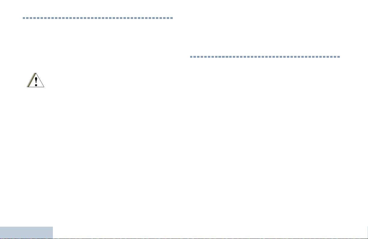
W celu uzyskania listy zatwierdzonych przez Motorolę
Ważne informacje dotyczące
anten, akumulatorów oraz innych akcesoriów należy
bezpieczeństwa
odwiedzić następującą stronę internetową:
http://www.motorolasolutions.com
Bezpieczne użytkowanie produktów i narażenie na
promieniowanie o częstotliwości radiowej (RF)
Przed rozpoczęciem korzystania z tego produktu
Wersja oprogramowania
należy przeczytać zalecenia dotyczące
bezpiecznego użytkowania, zamieszczone w
Wszystkie funkcje opisane w poniższych częściach są
broszurze "Zasady bezpiecznego używania
obsługiwane przez wersję oprogramowania R02.04.00.
wyrobu oraz narażenie na działanie
Przestroga
Aby uzyskać więcej informacji o wszystkich
promieniowania RF” (Product Safety and RF
instalowanych funkcjach, należy skontaktować się ze
Exposure) dostarczonej razem z radiotelefonem.
sprzedawcą lub administratorem systemu.
UWAGA!
Niniejszy radiotelefon jest przeznaczony wyłącznie
do zastosowań zawodowych, zgodnie z
wymaganiami komisji FCC/ICNIRP RF dotyczącymi
narażenia na promieniowanie RF. Przed rozpoczęciem
użytkowania należy przeczytać informacje dotyczące
zagrożeń związanych z promieniowaniem RF oraz
zapoznać się z instrukcjami dotyczącymi obsługi
urządzeń, zamieszczonymi w broszurze "Zasady
bezpiecznego używania wyrobu oraz narażenie na
działanie promieniowania RF” (Product Safety and RF
Exposure) dostarczonej razem z radiotelefonem (nr
Ważne informacje dotyczące bezpieczeństwa
publikacji firmy Motorola 6864117B25), aby zapewnić
zgodność z limitami narażenia na promieniowanie RF.
iv
Polski

Prawa autorskie dotyczące oprogramowania
TM
Technologia kodowania głosu AMBE+2
wykorzystana
Prawa autorskie dotyczące
w tym produkcie jest chroniona przez prawa firmy Digital
oprogramowania
Voice Systems Inc. dotyczące własności intelektualnej, z
prawami patentowymi i autorskimi oraz tajemnicą
Wyroby opisane w niniejszej instrukcji mogą zawierać
handlową włącznie.
programy zapisane w pamięciach półprzewodnikowych
lub innych podzespołach, które podlegają ochronie wg.
Ta technologia kodowania głosu jest licencjonowania
zasad praw autorskich do oprogramowania. Prawo
wyłącznie do użytku z tym wyposażeniem
Stanów Zjednoczonych Ameryki Północnej i innych
komunikacyjnym. Zabronione jest dekompilowanie,
krajów chroni interes firmy Motorola w zakresie
inżynieria wsteczna lub demontowanie kodu obiektowego
wyłączności własności programów komputerowych,
albo konwertowanie w inny sposób do czytelnej formy
włączając prawo do kopiowania i reprodukcji tych
przez użytkowników korzystających z tej technologii.
programów w jakiejkolwiek formie. Zgodnie z
Numery Pat. U.S.A.: #5,870,405, #5,826,222,
powyższym, każdy program komputerowy firmy Motorola
#5,754,974, #5,701,390, #5,715,365, #5,649,050,
objęty prawami autorskimi, zawarty w urządzeniach firmy
#5,630,011, #5,581,656, #5,517,511, #5,491,772,
Motorola opisywanych w niniejszej instrukcji może być
#5,247,579, #5,226,084 i #5,195,166.
skopiowany lub powielony w jakiejkolwiek formie
wyłącznie po uzyskaniu pisemnej zgody firmy Motorola.
Ponadto, zakup urządzeń firmy Motorola nie może być
traktowany bezpośrednio ani w domyśle, jako nabycie
praw do korzystania z licencji, patentów i zastosowań
patentów firmy Motorola, poza normalną eksploatacją
określoną w umowie kupna-sprzedaży.
v
Polski

• Nigdy nie wolno wtykać ostrych przedmiotów w otwór
Środki ostrożności
znajdujący się w obudowie. poniżej styków
akumulatora. Zadaniem otworu jest wyrównywanie
Przenośny cyfrowy radiotelefon serii MOTOTRBO
ciśnienia w urządzeniu. Ostre przedmioty mogą
spełnia normę IP57, która wymaga, aby urządzenie było
utworzyć drogę przedostawania się płynów do wnętrza
odporne na niekorzystne warunki polowe, np. zanurzenie
radiotelefonu i spowodować utratę szczelności.
w wodzie.
• Nigdy nie wolno zakrywać ani blokować otworu, np.
• Jeżeli radiotelefon został zanurzony w wodzie, należy
naklejką.
nim wstrząsnąć, aby usunąć wodę, która mogła dostać
• Nie wolno dopuszczać, aby do otworu dostały się
się do środka przez siatkę głośnika lub port mikrofonu.
substancje oleiste.
Woda może spowodować obniżenie skuteczności
urządzenia.
• Radiotelefon z poprawnie zamontowaną anteną jest
wodoszczelny do głębokości 1 metra (3,28 stóp) przez
• Jeżeli akumulator radiotelefonu był narażony na
maksymalnie 30 minut. Przekroczenie limitu czasu lub
działanie wody, przed jego ponownym montażem
niezamontowanie anteny może spowodować
należy oczyścić i wysuszyć styki zarówno akumulatora
uszkodzenie radiotelefonu.
jak i radiotelefonu. Pozostałości wody mogą
spowodować spięcie.
• Do czyszczenia radiotelefonu nie wolno stosować
spryskiwaczy, ponieważ ich ciśnienie może
• Jeżeli radiotelefon został zanurzony w substancji
przekraczać ciśnienie 1 metra wody, a tym samym
powodującej korozję (np. woda morska), należy
spowodować zalanie wnętrza radiotelefonu.
.
urządzenie oraz akumulator wymyć w słodkiej wodzie,
a następnie osuszyć.
Radiotelefonu nie wolno demontować. Może to
spowodować uszkodzenie uszczelek i utratę
• Do czyszczenia zewnętrznych powierzchni
szczelności urządzenia. Konserwację należy
radiotelefonu należy stosować roztwór łagodnego
przeprowadzać w serwisie, wyposażonym w
płynu do mycia naczyń i słodkiej wody (jedna łyżeczka
sprzęt do testowania i wymiany uszczelek
Środki ostrożności
detergentu na 4l wody).
radiotelefonu.
vi
Polski
Przestroga

Funkcje dostępne w konwencjonalnym trybie wielu miejsc są
Wprowadzenie
opisane w punkcie Łączenie z siecią IP na str.10.
Wprowadzenie
Wybrane funkcje są również dostępne w trybie trankingowym w
W tej sekcji omówiono następujące zagadnienia:
systemie zamkniętym (single site) Capacity Plus. Więcej informacji
Jak korzystać z Podręcznika użytkownika . . . . . . . . . . . . . . . str.1
w rozdziale pt. Capacity Plus na str.10.
Informacje udostępniane przez dystrybutora/
Wybrane funkcje są równiez dostępne w trybie trunkingu wielu
administratora systemu . . . . . . . . . . . . . . . . . . . . . . . . . . . str.1
miejsc, Linked Capacity Plus. Dodatkowe informacje podano w
punkcie Linked Capacity Plus na str.11.
Jak korzystać z Podręcznika użytkownika
Informacje udostępniane przez
Niniejszy Podręcznik użytkownika opisuje podstawowe funkcje
dystrybutora/administratora systemu
przewoźnych radiotelefonów MOTOTRBO bez wyświetlacza.
Lokalny dystrybutor lub administrator systemu może jednak
Można skontaktować się z lokalnym dystrybutorem lub
dostosować radiotelefon zgodnie z wymaganiami użytkownika. Aby
administratorem systemu, aby uzyskać następujące informacje:
uzyskać więcej informacji, należy skontaktować się z lokalnym
• Czy radiotelefon jest zaprogramowany z ustawieniami wstępnymi
dystrybutorem lub administratorem systemu.
kanałów konwencjonalnych?
Poniższe ikony używane w niniejszej instrukcji oznaczają funkcje
• Które przyciski zostały zaprogramowane w celu dostępu do
obsługiwane w standardowym trybie analogowym lub cyfrowym
innych funkcji?
Oznacza funkcję obsługiwaną wyłącznie w
• Jakie opcjonalne akcesoria mogą być zgodne z wymaganiami
standardowym trybie analogowym.
użytkownika?
• Jakie są najlepsze praktyki wykorzystania radiotelefonu dla
Oznacza funkcję obsługiwaną wyłącznie w
efektywnej komunikacji?
standardowym trybie cyfrowym.
• Jakie procedury konserwacji pomagają przedłużyć okres
Dla funkcji, które nie są dostępne w zarówno modelach
eksploatacji radiotelefonu?
analogowych i cyfrowych, nie pojawia się żadna ikona.
1
Polski

Ładowanie akumulatora
Przygotowanie radiotelefonu do pracy
Dla zapewnienia najwyższej sprawności, radiotelefon posiada
Radiotelefon należy przygotować do pracy wykonując następujące
akumulator niklowo-metalowo-jonowy (NiMH) lub litowo-jonowy
czynności:
(Li-Ion). Aby zapobiegać uszkodzeniom oraz przestrzegać
Ładowanie akumulatora . . . . . . . . . . . . . . . . . . . . . . . . . . . . . str. 2
warunków gwarancji, akumulator należy ładować przy użyciu
Instalowanie akumulatora . . . . . . . . . . . . . . . . . . . . . . . . . . . str. 3
ładowarki firmy Motorola i ściśle zgodnie z instrukcją dotyczącą
Podłączanie anteny . . . . . . . . . . . . . . . . . . . . . . . . . . . . . . . . str. 3
korzystania z ładowarki.
Instalacja zaczepu na pasek . . . . . . . . . . . . . . . . . . . . . . . . . str. 4
Aby zapewnić jak najlepszą wydajność, akumulator należy ładować
Nakładanie osłony złącza uniwersalnego
od 14 do 16 godzin przed pierwszym użyciem.
(przeciwpyłowej). . . . . . . . . . . . . . . . . . . . . . . . . . . . . . . . . str. 4
Włączanie radiotelefonu. . . . . . . . . . . . . . . . . . . . . . . . . . . . . str. 5
WAŻNE: Aby zapewnić optymalną żywotność i odpowiednie
Regulacja głośności . . . . . . . . . . . . . . . . . . . . . . . . . . . . . . . . str. 5
parametry akumulatora, należy ZAWSZE ładować
akumulator IMPRES za pomocą ładowarki IMPRES.
Akumulatory IMPRES ładowane wyłącznie za pomocą
ładowarek IMPRES otrzymują 6-miesięczne
przedłużenie gwarancji na pojemność ponad okres
gwarancji dla standardowych akumulatorów Motorola
Premium.
Przygotowanie radiotelefonu do pracy
2
Polski

Instalowanie akumulatora
Podłączanie anteny
Ustaw akumulator zgodnie z prowadnicami na tylnym panelu
Przygotowanie radiotelefonu do pracy
Wyłącz radiotelefon, ustaw antenę w
obudowy radiotelefonu. Dociśnij akumulator zdecydowanie i
złączu i obróć w kierunku zgodnym z
przesuń do góry, tak aby został zablokowany w odpowiednim
ruchem wskazówek zegara.
.
położeniu. Przesuń zatrzask akumulatora do położenia
zablokowanego.
Aby wyjąć antenę, należy obrócić ją w
lewo.
Aby wyjąć
akumulator, wyłącz
radiotelefon.
Przesuń zatrzask
akumulatora, aby
zwolnić blokadę, a
następnie
przytrzymaj i
przesuń akumulator
w dół i wysuń z
prowadnic.
3
Polski
Zatrzask
akumulatora
Jeżeli konieczna jest wymiana anteny, należy
korzystać tylko z anten MOTOTRBO. Ignorowanie
tego zalecenia może być przyczyną uszkodzenia
radiotelefonu.
Przestroga
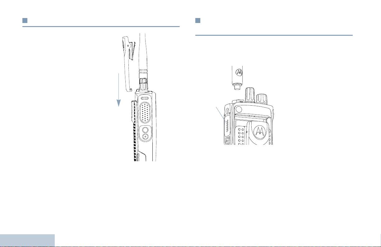
Instalacja zaczepu na pasek
Nakładanie osłony złącza uniwersalnego
(przeciwpyłowej)
Ustaw szczeliny na zaczepie
Złącze uniwersalne znajduje się na bocznym panelu obudowy
zgodnie ze szczelinami w
radiotelefonu po stronie anteny. Służy do podłączania akcesoriów
akumulatorze i dociśnij aż do
MOTOTRBO do radiotelefonu.
chwili, kiedy zaczep zostanie
Umieść zaczepy na
zablokowany w odpowiednim
zakończeniu pokrywy w
położeniu.
szczelinach powyżej złącza
uniwersalnego. Dociśnij
Aby zdjąć zacisk, należy
pokrywę, aby umieścić dolny
nacisnąć i zsunąć skrzydełko
zaczep prawidłowo w złączu
zacisku z akumulatora. Można
RF.
posłużyć się kluczem.
Obróć śrubę skrzydełkową,
Następnie przesuń zatrzask w
aby zamocować pokrywę
górę i odłącz od radiotelefonu.
złącza w radiotelefonie.
Aby zdjąć pokrywę złącza
uniwersalnego, dociśnij pokrywę i obróć śrubę skrzydełkową w
kierunku przeciwnym do ruchu wskazówek zegara.
Osłonę przeciwpyłową należy nakładać, gdy nie korzysta się ze
złą
cza uniwersalnego.
Przygotowanie radiotelefonu do pracy
4
Polski
Złącze
uniwersalne
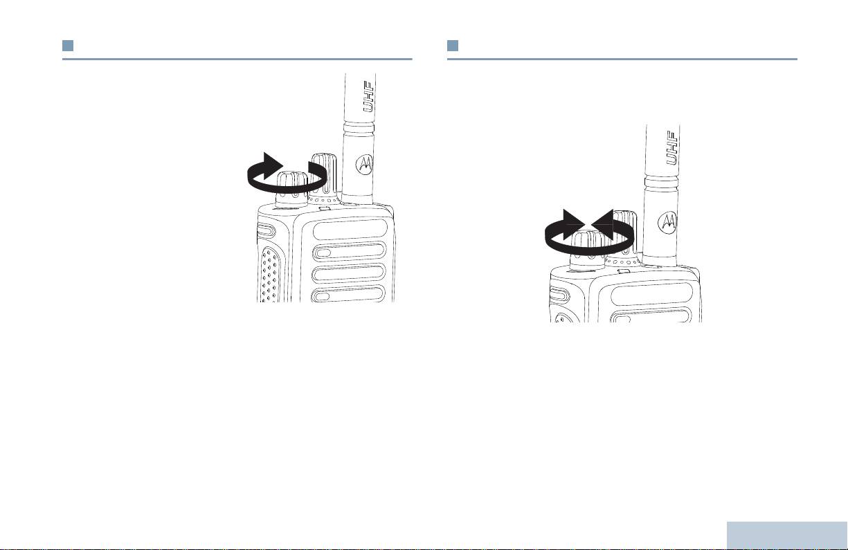
Włączanie radiotelefonu
Regulacja głośności
Przygotowanie radiotelefonu do pracy
Aby włączyć radiotelefon obróć
Aby zwiększyć głośność, należy obrócić pokrętło Wł/Wył/
pokrętło Wł/Wył/Regulacja
Regulacja głośności w kierunku zgodnym z ruchem wskazówek
głośności w kierunku
zegara.
zgodnym z ruchem
wskazówek zegara aż do
usłyszenia kliknięcia. Zielony
wskaźnik zostaje włączony.
Generowany jest krótki sygnał
dźwiękowy informujący o
pomyślnym przeprowadzeniu
testu automatycznego.
UWAGA: Sygnał dźwiękowy
nie jest generowany
podczas włączania
zasilania, jeżeli
dźwięki/alerty radiotelefonu są wyłączone (zob.
Włączanie/wyłączanie dźwięków/alertów
radiotelefonu na str. 37).
Aby zmniejszyć głośność, należy obrócić to pokrętło w kierunku
przeciwnym do ruchu wskazówek zegara.
Jeżeli radiotelefon nie jest włączany, należy sprawdzić akumulator
upewniając się, czy jest naładowany i właściwie zainstalowany.
UWAGA: W radiotelefonie można zaprogramować minimalną
Jeżeli radiotelefon nadal nie jest włączany, należy skontaktować się
głośność. Nie będzie można wyciszyć urządzenia
z lokalnym dystrybutorem.
poniżej tej wartości. Szczegółowe informacje można
Aby wyłączyć radiotelefon, należy obrócić pokrętło w kierunku
uzyskać od dealera lub administratora systemu.
przeciwnym do ruchu wskazówek zegara aż do usłyszenia
kliknięcia
5
Polski

Elementy regulacyjne radiotelefonu
W tej sekcji omówiono następujące zagadnienia:
Najczęściej używane elementy regulacyjne radiotelefonu . . . str. 6
Przyciski programowane . . . . . . . . . . . . . . . . . . . . . . . . . . . . str. 7
Przycisk nadawania (PTT) . . . . . . . . . . . . . . . . . . . . . . . . . . . str. 8
Przełączanie pomiędzy konwencjonalnym trybem
analogowym a cyfrowym . . . . . . . . . . . . . . . . . . . . . . . . . . str. 9
Łączenie z siecią IP . . . . . . . . . . . . . . . . . . . . . . . . . . . . . . . str. 10
Capacity Plus . . . . . . . . . . . . . . . . . . . . . . . . . . . . . . . . . . . . str. 10
Linked Capacity Plus . . . . . . . . . . . . . . . . . . . . . . . . . . . . . . str. 11
Najczęściej używane elementy
regulacyjne radiotelefonu
Pokrętło wyboru kanałów
Pokrętło Wł/Wył/Regulacja głośności
Wskaźnik świetlny
Przycisk boczny 1
*
Przycisk nadawania (PTT)
Przycisk boczny 2
*
Elementy regulacyjne radiotelefonu
Przycisk boczny 3*
Mikrofon
6
Polski
1
2
3
4
5
6
7
8
Głośnik
Uniwersalne złącze do akcesoriów
Przycisk awaryjny
*
Antena
*Te przyciski są programowane.
1
12
2
11
10
3
4
9
5
8
6
7
9
10
11
12

Zapowiedź głosowa dla kanału – Odtwarza zapowiedzi głosowe
Przyciski programowane
strefy i kanału dla bieżącego kanału. Ta funkcja jest niedostępna,
Elementy regulacyjne radiotelefonu
Sprzedawca może zaprogramować programowane przyciski jako
kiedy Zapowiedź głosowa jest wyłączona.
skróty do funkcji radiotelefonu lub kanały/grupy zależnie od
Tryb awaryjny – Zależ
nie od zaprogramowanej konfiguracji
długości naciśnięcia przycisku:
inicjowanie lub anulowanie alarmu awaryjnego lub połączenia.
• Krótkie naciśnięcie – Szybkie naciśnięcie i zwolnienie przycisku.
Wł. / Wył. Inteligentnego dźwięku – Włącza i wyłącza funkcję
• Długie naciśnięcie – Naciśnięcie i przytrzymanie przez
Inteligentnego dźwięku.
zaprogramowany czas.
‡
Ręczne szukanie sieci*
– Rozpoczyna ręczne szukanie
• Przytrzymanie – Naciśnięcie i przytrzymanie przycisku.
sieci.
UWAGA: Zaprogramowany czas naciśnięcia przycisku obowiązuje
dla wszystkich przypisywanych funkcji lub ustawień
Wł. / Wył. AGC Mik. – Włącza i wyłącza automatyczne
radiotelefonu/urządzenia dodatkowego. Więcej
wzmocnienie wewnętrznego mikrofonu (AGC). Funkcja
informacji na temat zaprogramowanego czasu
niedostępna w trakcie sesji Bluetooth.
naciśnięcia przycisku Tryb awaryjny znajduje się w
Monitorowanie – Korzystając z tej funkcji, można monitorować
części Działanie w trybie alarmowym na str. 27.
aktywność w wybranym kanale
‡
Eliminacja kanału uciążliwego*
– Tymczasowe usunięcie
Konfigurowalne funkcje radiotelefonu
niepożądanego kanału, z wyjątkiem wybranego kanału, z listy
TM
Bluetooth
Włącznik audio – Przełącza routing audio pomiędzy
skanowania. Wybrany kanał dotyczy wybranej przez użytkownika
wewnętrznym głośnikiem radiotelefonu a zewnętrznym
kombinacji strefa/kanał, z którego skanowanie jest inicjowane.
urządzeniem Bluetooth.
Szybki dostęp – Bezpośrednio inicjuje wcześniej
Połączenie Bluetooth – Inicjuje operację Bluetooth "znajdź i
zaprogramowane Wywołanie indywidualne lub grupowe, Sygnał
połącz.
wywołania lub Szybki tekst.
Rozłączenie Bluetooth – Kończy wszystkie istniejące połączenia
Funkcja płytki opcji – Włączanie lub wyłączanie funkcji płytki opcji
Bluetooth pomiędzy radiotelefonem i urządzeniami Bluetooth.
dla kanałów uaktywnianych płytką opcji.
Przekierowanie wywołania – Włącza lub wyłącza funkcję
Przekierowania wywołania.
7
Polski
* Nie dotyczy trybu Capacity Plus
‡
Nie dotyczy Linked Capacity Plus
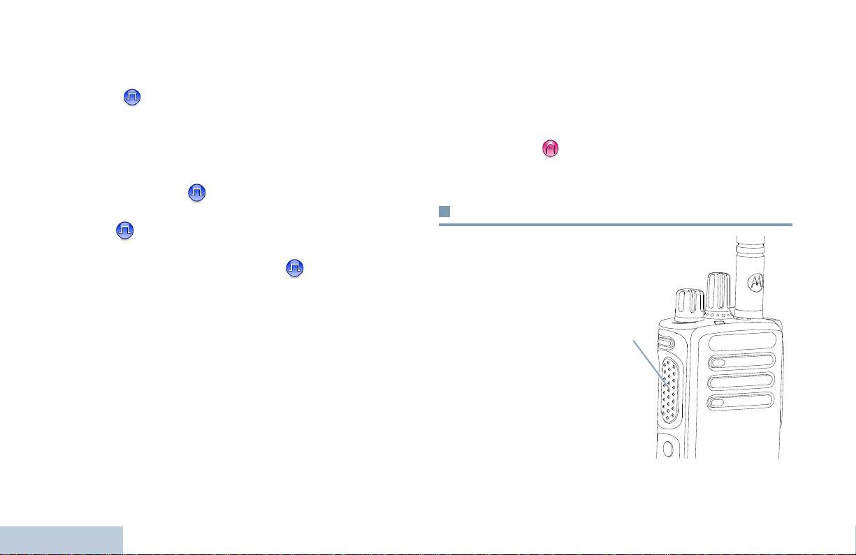
‡
Stałe włączenie monitora*
– Monitorowanie wybranego kanału
Konfigurowalne ustawienia/narzędzia
dla całego ruchu radiowego aż do chwili, kiedy ta funkcja zostanie
wyłączona.
Wszystkie dźwięki/Alerty – Włączenie lub wyłączenie wszystkich
Prywatność – Włączanie lub wyłączanie funkcji prywatności.
sygnałów dźwiękowych.
‡
Przekaźnik/Bez przekaźnika*
– Przełączanie między trybem
Poziom mocy – Przełączanie wysokiego i niskiego poziomu mocy
korzystania z przekaźnika i komunikowaniem się bezpośrednio z
nadawania.
innym radiotelefonem.
Blokada szumów
– Przełączanie normalnej i silnej blokady
‡
Skanowanie*
– Włączenie lub wyłączenie skanowania.
szumów.
Połącz/rozłącz z siecią* – Włącza lub wyłącza automatyczne
szukanie sieci.
Przycisk nadawania (PTT)
Telemetria – Kontrolowanie końcówki wyjściowej
radiotelefonu lokalnego lub zdalnego.
Przycisk PTT na bocznym
Zdalne wyłączenie przerwania transmisji – Zatrzymuje
panelu obudowy mikrofonu
aktualne, przerywalne wywołanie, by zwolnić kanał.
pełni dwie podstawowe
funkcje:
Zapowiedź głosowa wł. / wył. – Włącza i wyłącza funkcję
Zapowiedzi głosowej
• Po nawiązaniu
połączenia przycisk PTT
Nadawanie uruchamiane głosem (VOX) – Włącza lub wyłącza
umożliwia nadawanie do
funkcję VOX.
innych radiotelefonów
Strefa – Umożliwia wybór strefy z listy.
uwzględnionych w
danym połączeniu.
Stan akumulatora – Wskaźnik LED pokazuje stan naładowania
akumulatora.
Naciśnij i przytrzymaj
przycisk PTT, aby mówić
Elementy regulacyjne radiotelefonu
do mikrofonu. Aby
słuchać, zwolnij przycisk
PTT.
Mikrofon jest włączany po naciśnięciu przycisku PTT.
8
Polski
* Nie dotyczy trybu Capacity Plus
‡
Nie dotyczy Linked Capacity Plus
Przycisk
PTT
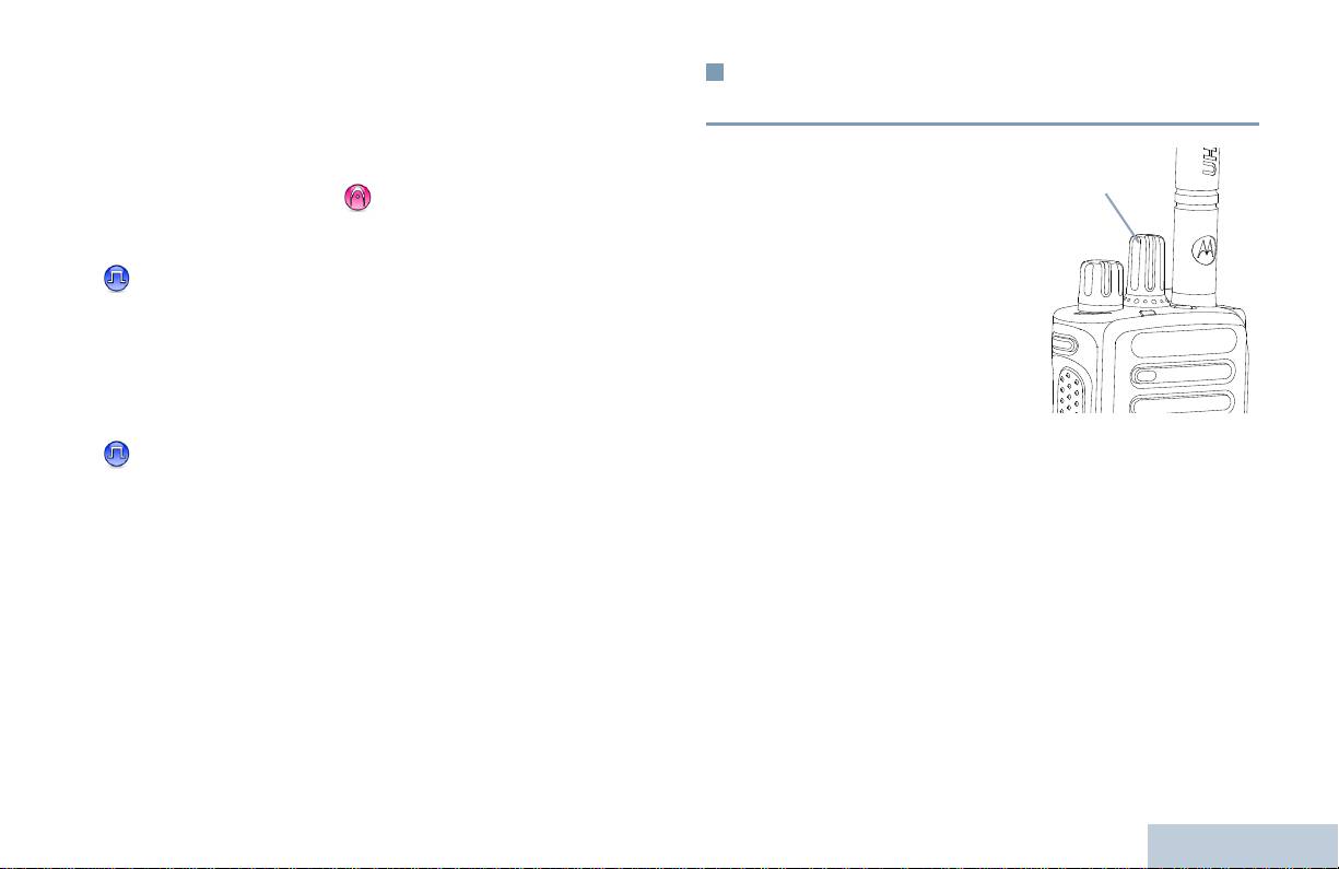
• Jeżeli połączenie nie zostało nawiązane, przycisk PTT umożliwia
Przełączanie pomiędzy konwencjonalnym
zainicjowanie nowego połączenia (zob.
Inicjowanie
trybem analogowym a cyfrowym
połączenia radiowego
na str. 18).
Elementy regulacyjne radiotelefonu
Zależnie od zaprogramowania, jeżeli jest włączony ton Zezwolenia
Każdy kanał radiotelefonu
można skonfigurować jako
na rozmowę lub sygnał PTT ,
czekaj na zakończenie krótkiego
konwencjonalny kanał
sygnału dźwiękowego, zanim zaczniesz mówić.
analogowy lub cyfrowy.
Korzystając z pokrętła wyboru
Podczas połączenia jeżeli funkcja wskazywania wolnego
kanałów, można uaktywniać
kanału jest włączona w radiotelefonie (zaprogramowana przez
kanał analogowy lub cyfrowy.
dystrybutora) usłyszysz krótki dźwięk alertu w chwili, gdy
Podczas przełączania trybu
przycisk PTT zostanie zwolniony w radiotelefonie docelowym
cyfrowego do analogowego
(radiotelefon, który odbiera połączenie) wskazujący, że kanał
niektóre funkcje są
jest wolny i można odpowiadać.
niedostępne.
Jezeli wywolanie zostaje zaklócone, slychac ciagly sygnal
Niektóre funkcje radiotelefonu są dostępne zarówno w trybie
przerwania rozmowy, wskazujacy, ze nalezy zwolnic przycisk
analogowym, jak i cyfrowym. Nieistotne różnice w sposobie
PTT, np. gdy radiotelefon odbiera Wywolanie awaryjne.
działania poszczególnych funkcji NIE wpływają jednak na
wydajność radiotelefonu.
UWAGA: Radiotelefon jest również przełączany między trybem
analogowym i cyfrowym podczas skanowania w dwóch
trybach (zob.
Skanowanie na str. 24).
9
Polski
Pokrętło wyboru kanałów

Łączenie z siecią IP
Capacity Plus
Ta funkcja pozwala na rozszerzenie standardowej komunikacji
Capacity Plus to zamknięta, trankingowa konfiguracja systemu
poza zasięg jednego miejsca, przez połączenie wielu dostępnych
radiowego MOTOTRBO, która korzysta z określonej puli kanałów
miejsc, tworzących sieć IP (Internet Protocol).
do obsługi setek użytkowników i nawet 254 grup. Funkcja ta
pozwala na skuteczne wykorzystywanie dostępnej liczby
Gdy radiotelefon opuszcza zasięg jednego miejsca i wchodzi w
zaprogramowanych kanałów w trybie przemiennika (Repeater).
zasięg innego, łączy się on z przemiennikiem nowego miejsca, aby
wysyłać lub odbierać wywołania/transmisję danych. Zależnie od
Ikony funkcji nieobsługiwanych w Capacity Plus nie będą dostępne
skonfigurowanych ustawień radiotelefon jest przełączany
w menu. W przypadku naciśnięcia przycisku programowalnego do
automatycznie lub ręcznie.
obsługi funkcji niedostępnej w Capacity Plus rozlegnie się
odpowiedni sygnał dźwiękowy.
Po wybraniu automatycznej zmiany ustawień urządzenie skanuje
wszystkie dostępne sieci, gdy sygnał aktualnie używanej sieci jest
Radiotelefon posiada również funkcje dostępne w standardowym
słaby lub nie można uzyskać sygnału. Następnie synchronizuje się
trybie cyfrowym, Podłączenie trybu Miejsca IP, Capacity Plus oraz
on z przemiennikiem o najsilniejszej wartości wskaźnika poziomu
Linked Capacity Plus. Jednak niewielkie różnice w działaniu
sygnału odbieranego (RSSI).
poszczególnych funkcji NIE wpływają na ogólne parametry i
wydajność urządzenia.
Po wybraniu ręcznej zmiany ustawień urządzenie szuka kolejnej
dostępnej w zasięgu sieci z listy szukania (choć niekoniecznie o
Szczegółowe informacje na temat tej konfiguracji można uzyskać
najsilniejszym sygnale), a następnie się z nią łączy.
od dealera lub administratora systemu.
UWAGA: Dla każdego kanału można włączyć albo Skanowanie,
albo Szukanie sieci – nigdy obie funkcje jednocześnie.
Kanały, dla których włączono tę funkcję, można dodać do wybranej
listy szukania. Radiotelefon automatycznie przeszukuje kanał(y) w
liście roamingowej, aby zlokalizować najlepsze miejsce.
Lista roamingowa obsługuje maksymalnie 16 kanałów (łącznie z
Wybranym kanałem).
Elementy regulacyjne radiotelefonu
Wpisów na liście nie można dodawać ani usuwać ręcznie. Więcej
informacji uzyskasz od sprzedawcy lub administratora sieci.
10
Polski

Kanały z włączoną opcją Linked Capacity Plus można dodać do
Linked Capacity Plus
dowolnej listy roamingowej. Radiotelefon przeszukuje te kanały w
trakcie automatycznego roamingu, aby wyszukać najlepsze
Elementy regulacyjne radiotelefonu
Linked Capacity Plus to wielokanałowa konfiguracja trunkingu wielu
miejsce.
miejsc urządzeń radiowych MOTOTRBO, która łączy w sobie
najlepsze cechy konfiguracji Capacity Plus i Podłączenia Trybu
UWAGA: Wpisów na liście nie można dodawać ani usuwać
Miejsca IP.
ręcznie. Więcej informacji uzyskasz od sprzedawcy lub
administratora sieci.
Linked Capacity Plus pozwala na rozszerzenie komunikacji
Podobnie jak w Capacity Plus, ikony funkcji nie mających
trunkingowej poza zasięg jednego miejsca, przez połączenie wielu
zastosowania w Linked Capacity Plus nie są dostępne w menu.
dostępnych miejsc, tworzących sieć IP (Internet Protocol). Daje
Zabrzmi negatywny sygnał przy próbie uruchomienia funkcji, która
ona również lepszą przepustowość dzięki łącznym wykorzystaniu
nie jest funkcją Linked Capacity Plus, przez naciśnięcie
dostępnych zaprogramowanych kanałów, obsługiwanych przez
programowalnego przycisku.
każde dostępne miejsce.
Szczegółowe informacje na temat tej konfiguracji można uzyskać
Gdy radiotelefon opuszcza zasięg jednego miejsca i wchodzi w
od dealera lub administratora systemu.
zasięg innego, łączy się on z przemiennikiem nowego miejsca, aby
wysyłać lub odbierać wywołania/transmisję danych. Zależnie od
skonfigurowanych ustawień radiotelefon jest przełączany
automatycznie lub ręcznie.
Po wybraniu automatycznej zmiany ustawień urządzenie skanuje
wszystkie dostępne sieci, gdy sygnał aktualnie używanej sieci jest
słaby lub nie można uzyskać sygnał
u. Następnie synchronizuje się
on z przemiennikiem o najsilniejszej wartości wskaźnika poziomu
sygnału odbieranego (RSSI).
Po wybraniu ręcznej zmiany ustawień urządzenie szuka kolejnej
dostępnej w zasięgu sieci z listy szukania (choć niekoniecznie o
najsilniejszym sygnale), a następnie się z nią łączy.
11
Polski
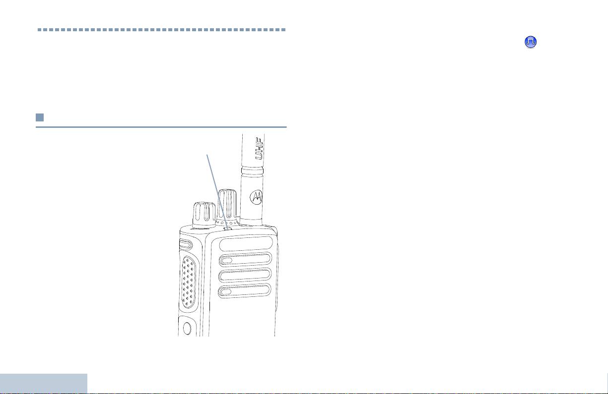
Podwójnie pulsujące światło zielone –
Radiotelefon odbiera
Wskaźniki stanu
połączenie lub dane przy włączonej funkcji prywatności.
.
Stałe światło żółte –Radiotelefon monitoruje kanał
Następujące wskaźniki sygnalizują stan operacyjny radiotelefonu:
konwencjonalny. Oznacza również dostateczne naładowanie
Wskaźniki świetlne . . . . . . . . . . . . . . . . . . . . . . . . . . . . . . . . str. 12
akumulatora, jeżeli jest wciśnięty przycisk Stanu akumulatora.
Sygnały dźwiękowe . . . . . . . . . . . . . . . . . . . . . . . . . . . . . . . str. 13
Pulsujące światło żółte – Radiotelefon wykonuje skan aktywności
Sygnały wskaźnikowe . . . . . . . . . . . . . . . . . . . . . . . . . . . . . str. 13
lub odbiera Sygnał wywołania bądź wszystkie lokalne kanały
Linked Capacity Plus są zajęte.
Wskaźniki świetlne
Podwójnie pulsujące światło żółte – Radiotelefon nie jest
podłączony do przemiennika w systemie Capacity Plus, wszystkie
Dioda LED pokazuje stan
kanały Capacity są aktualnie zajęte, Auto Roaming jest wyłączony,
operacyjny radiotelefonu.
radiotelefon aktywnie poszukuje nowej strony. Oznacza również, że
Pulsujące światło czerwone –
radiotelefon musi jeszcze odpowiedzieć na alarmowe wywołanie
Radiotelefon odbiera transmisję
grupowe lub jest zablokowany.
awaryjną lub nie powiódł się
UWAGA: W trybie konwencjonalnym, kiedy dioda LED pulsuje na
automatyczny test podczas
zielono, radiotelefon wykrywa aktywność w eterze. Ze
uruchamiania.
względu na charakter protokołu cyfrowego, aktywność ta
może lub nie oddziaływać na zaprogramowany kanał
Stałe światło zielone
–
radiotelefonu.
Radiotelefon uruchamia się lub
nadaje. Oznacza również pełne
Dla Capacity Plus i Linked Capacity Plus, nie ma
naładowanie akumulatora, jeżeli
wskazania LED, gdy radiotelefon wykrywa aktywność w
jest wciśnięty przycisk
eterze.
Naładowania akumulatora.
Pulsujące światło zielone
–
Radiotelefon odbiera
Wskaźniki stanu
niezabezpieczone wywołanie/
dane bądź wykrywa aktywność
radiową
12
Polski
Wskaźnik
świetlny
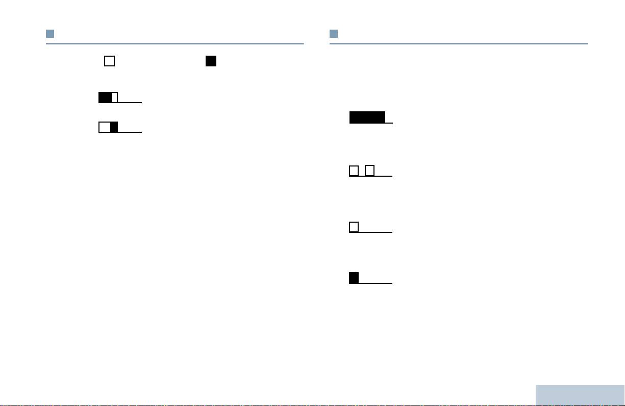
Sygnały wskaźnikowe
Sygnały dźwiękowe
Wskaźniki stanu
Sygnały dźwiękowe potwierdzają stan radiotelefonu lub odpowiedź
Sygnał wysoki Sygnał niski
radiotelefonu na odbierane dane.
Sygnał
Sygnał potwierdzenia
Dźwięk monotoniczny. Ciągły do
ciągły
zakończenia.
Sygnał blokady
Sygnał
Generowany okresowo zależnie od
okresowy
konfiguracji radiotelefonu. Dźwięk jest
włączany, przerywany i powtarzany
automatycznie.
Sygnał
Pojedynczy dźwięk powtarzany aż do
powtarzany
chwili, kiedy zostanie przerwany przez
użytkownika.
Sygnał
Generowany tylko jeden raz przez krótki
jednorazowy
czas określony przez radiotelefon.
13
Polski
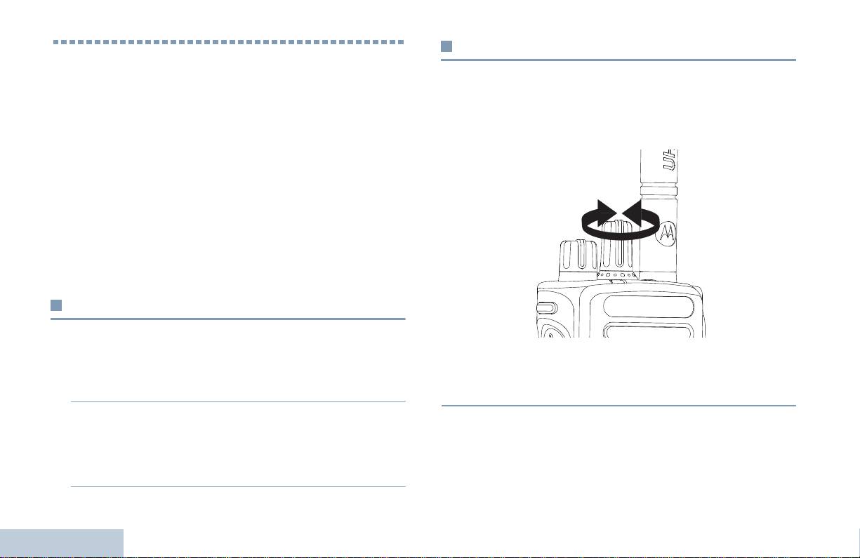
Wybór kanalu
Inicjowanie i odbieranie połączeńs
Transmisje są nadawane i odbierane na kanale. W zależności od
Po zapoznaniu się ze sposobem konfigurowania radiotelefonu
konfiguracji radiotelefonu, każdy kanał może być inaczej
przenośnego MOTOTRBO można rozpocząć korzystanie z
zaprogramowany w celu obsługi różnych grup użytkowników lub
radiotelefonu.
może posiadać różne funkcje. Po wybraniu wymaganej strefy,
Aby uzyskać więcej informacji dotyczących podstawowych funkcji
wybierz kanał, na którym chcesz nadawać lub odbierać.
związanych z połączeniami, skorzystaj z poniższej listy:
Wybór strefy . . . . . . . . . . . . . . . . . . . . . . . . . . . . . . . . . . . . . str. 14
Wybór kanalu . . . . . . . . . . . . . . . . . . . . . . . . . . . . . . . . . . . . str. 14
Odbieranie połączenia radiowego . . . . . . . . . . . . . . . . . . . . str. 15
Inicjowanie połączenia radiowego . . . . . . . . . . . . . . . . . . . . str. 18
Zatrzymywanie Wywołania radiotelefonu. . . . . . . . . . . . . . . str. 21
Pomijanie przekaźnika . . . . . . . . . . . . . . . . . . . . . . . . . . . . . str. 21
Funkcje monitorowania . . . . . . . . . . . . . . . . . . . . . . . . . . . . str. 22
Wybór strefy
Radiotelefon obsługuje do 32 kanałów oraz 2 strefy, przy
maksymalnej liczbie 16 kanałów na strefę.
Procedura:
Procedura:
Obróć pokrętło Wyboru kanału, aby wybrać kanał o aktywnym
1 Naciśnij zaprogramowany przycisk Strefy.
aliasie lub ID grupy.
2 Zabrzmi sygnał pozytywny - potwierdzający, że radiotelefon
przełączył się ze Strefy 1 na Strefę 2.
LUB
Inicjowanie i odbieranie połączeńs
Zabrzmi sygnał negatywny - oznaczający, że radiotelefon
przełączył się ze Strefy 2 na Strefę 1.
14
Polski
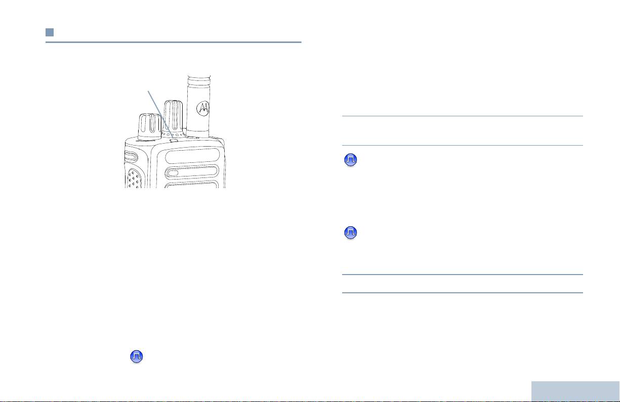
Odbieranie połączenia radiowego
Odbieranie połączenia grupowego
Aby odebrać połączenie od grupy użytkowników, radiotelefon musi
Po wyświetleniu kanału, identyfikatora abonenta lub identyfikatora
Inicjowanie i odbieranie połączeńs
być skonfigurowany jako członek danej grupy.
grupy można odbierać połączenia i odpowiadać na połączenia.
Procedura:
1 Zielony wskaźnik miga. Radiotelefon włącza głos i wszystkie
przychodzące wywołania są słyszalne przez głośnik
urządzenia.
2 Aby odebrać wywołanie, trzymaj radiotelefon pionowo,
1 - 2 cale (2,5 do 5,0 cm) od ust.
3 Jeżeli funkcja wskazywania wolnego kanału jest
włączona, usłyszysz krótki dźwięk alertu w chwili gdy przycisk
PTT zostanie zwolniony w radiotelefonie transmitującym,
Zielony wskaźnik jest włączony wówczas, gdy radiotelefon jest
wskazujący że kanał jest wolny i można odpowiadać.
przełączony do trybu nadawania i miga po przełączeniu
Naciśnij przycisk PTT, by odpowiedzieć na wywołanie.
radiotelefonu do trybu odbioru.
LUB
UWAGA: Dioda LED pali się ciągłym zielonym światłem, gdy
Jeżeli jest aktywna funkcja Przerwanie głosu, naciśnij
radiotelefon nadaje, a podwójnie pulsuje na zielono
przycisk PTT, by zatrzymać aktualne wywołanie z
podczas odbioru wywołania z aktywną funkcją
transmitującego radiotelefonu i zwolnić kanał do rozmowy/
prywatności.
odpowiedzi.
Po włączeniu funkcji ochrony prywatności transmisję
będą mogły odszyfrować tylko radiotelefony z takim
4 Zielony wskaźnik zostaje włączony.
samym kluczem zabezpieczającym LUB taką samą
5 Poczekaj na zakończenie sygnału zezwolenia na rozpoczęcie
wartością i identyfikatorem klucza (programowane przez
rozmowy (jeżeli jest włączony) i zacznij mówić wyraźnie do
sprzedawcę), jak te skonfigurowane w Twoim
mikrofonu.
radiotelefonie.
LUB
Patrz Prywatność na str. 31, aby znaleźć więcej
informacji.
15
Polski
Wskaźnik
świetlny
Jeżeli jest aktywna funkcja Przerwanie głosu, naciśnij przycisk
Odczekaj, aż zamilknie sygnał PTT (jeżeli jest aktywny) i
PTT, by zatrzymać aktualne wywołanie z transmitującego
mów wyraźnie do mikrofonu.
radiotelefonu i zwolnić kanał do rozmowy/odpowiedzi.
6 Aby słuchać, zwolnij przycisk PTT.
4 Zielony wskaźnik zostaje włączony.
7 W przypadku braku aktywności głosowej w zaprogramowanym
5 Poczekaj na zakończenie sygnału zezwolenia na rozpoczęcie
interwale czasowym połączenie zostanie zakończone.
rozmowy (jeżeli jest włączony) i zacznij mówić wyraźnie do
mikrofonu.
Aby uzyskać szczegółowe informacje dotyczące inicjowania
6 Aby słuchać, zwolnij przycisk PTT.
połączenia grupowego, zob.
Inicjowanie połączenia
grupowego na str. 18.
7 W przypadku braku aktywności głosowej w zaprogramowanym
interwale czasowym połączenie zostanie zakończone.
8 Zostanie wygenerowany krótki sygnał dźwiękowy. Na
Odbieranie połączenia prywatnego
wyświetlaczu widoczny jest komunikat Połączenie
Połączenie prywatne jest inicjowane przez indywidualny
zakończone.
radiotelefon i skierowane do innego indywidualnego radiotelefonu.
Aby uzyskać szczegółowe informacje dotyczące inicjowania
Procedura:
połączenia prywatnego, zob Inicjowanie połączenia prywatnego
Podczas odbierania połączenia prywatnego:
na str. 19.
1 Wskaźnik miga zielonym światłem. Radiotelefon włącza głos i
wszystkie przychodzące wywołania są słyszalne przez głośnik
urządzenia.
2 Aby odebrać wywołanie, trzymaj radiotelefon pionowo,
1 - 2 cale (2,5 do 5,0 cm) od ust.
3 Jeżeli funkcja wskazywania wolnego kanału jest włączona,
usłyszysz krótki dźwięk alertu w chwili gdy przycisk PTT
zostanie zwolniony w radiotelefonie transmitującym,
Inicjowanie i odbieranie połączeńs
wskazujący że kanał jest wolny i można odpowiadać.
Naciśnij przycisk PTT, by odpowiedzieć na wywołanie.
LUB
16
Polski

Odbieranie i reagowanie na Wywołanie
Odbieranie połączenia zbiorczego
selektywne
Połączenie zbiorcze jest inicjowane przez indywidualny radiotelefon
Inicjowanie i odbieranie połączeńs
i skierowane do wszystkich radiotelefonów w danym kanale. Jest
Wywołanie selektywne to połączenie pojedynczego radiotelefonu z
ono używane do transmitowania ważnych zawiadomień
innym radiotelefonem indywidualnym. W systemie analogowym
wymagających pełnej uwagi użytkowników.
takie połączenie to Wywołanie indywidualne.
Procedura:
Procedura:
Podczas odbierania połączenia zbiorczego:
Wywołanie selektywne sygnalizowane jest przez:
1 Generowany jest sygnał dźwiękowy i zielony wskaźnik miga.
1 Dioda LED pulsuje na zielono.
Radiotelefon włącza głos i wszystkie przychodzące wywołania
są słyszalne przez głośnik urządzenia.
2 Aby odebrać wywołanie, trzymaj radiotelefon pionowo,
1 - 2 cale (2,5 do 5,0 cm) od ust.
Radiotelefon włącza głos i
2 Jeżeli przez zdefiniowany czas nie ma aktywności głosowej,
wszystkie przychodzące wywołania są słyszalne przez głośnik
Wywołanie wszystkich zostaje zakończone.
Wywołanie
urządzenia.
wszystkich zostaje zakończone bez odczekiwania przez
predefiniowany czas.
3 Jeżeli jest włączona funkcja Sygnalizacja wolnego kanału,
przez chwilę rozbrzmiewa ton powiadamiający, gdy nadający
Jeżeli funkcja wskazywania wolnego kanału jest
radiotelefon zwalnia przycisk PTT, co oznacza, że kanał jest
włączona, usłyszysz krótki dźwięk alertu w chwili gdy przycisk
wolny i można odpowiedzieć.
PTT zostanie zwolniony w radiotelefonie transmitującym,
4 Naciśnij przycisk PTT, by odpowiedzieć na wywołanie. Dioda
wskazujący że kanał jest teraz dostępny i można nadawać.
LED pali się stałym zielonym światłem.
Nie można odpowiadać na połączenie zbiorcze.
5 Zaczekaj, aż zamilknie Ton pozwolenia na rozmowę (o ile jest
aktywny) i wyraźnie mów do mikrofonu.
UWAGA: Radiotelefon przerywa odbiór połączenia zbiorczego
jeżeli użytkownik przełączy kanał podczas odbierania
6 Zwolnij przycisk PTT, aby nasłuchiwać..
połączenia.
7 Jeżeli przez zdefiniowany czas nie ma aktywności głosowej,
Podczas połączenia zbiorczego, nie można korzystać z
wywołanie zostaje zakończone.
funkcji przycisków zaprogramowanych aż do
zakończenia połączenia.
8 Słychać krótki sygnał.
Zobacz
Wykonywanie Wywołania selektywnego na str. 19,
aby uzyskać więcej informacji o Wywołaniu selektywne.
17
Polski
Procedura:
Inicjowanie połączenia radiowego
1 Wybierz kanał z aktywnym aliasem lub ID grupy. Zobacz punkt
Wybór kanalu
na str. 14.
Po wybraniu kanału, można wybrać alias lub ID abonenta bądź
LUB
alias lub ID grupy, wykorzystując:
Naciśnij zaprogramowany przycisk Szybkiego dostepu.
• Pokrętło wyboru kanałów
2 Trzymaj radiotelefon w pozycji pionowej w odległości
• Zaprogramowany przycisk Szybkie wywołanie
2,5 – 5,0 cm od ust.
UWAGA:
Radiotelefon musi mieć włączoną funkcję prywatności
3 Naciśnij przycisk PTT, aby zainicjować połączenie. Zielony
na danym kanale, aby nadawać podczas połączenia
wskaźnik zostaje włączony.
prywatnego. Transmisję będą mogły odszyfrować tylko
4 Poczekaj na zakończenie sygnału zezwolenia na rozpoczęcie
radiotelefony z takim samym kluczem zabezpieczającym
LUB taką samą wartością i identyfikatorem klucza, jak w
rozmowy (jeżeli jest włączony) i zacznij mówić wyraźnie do
Twoim radiotelefonie.
mikrofonu.
LUB
Patrz
Prywatność na str. 31, aby znaleźć więcej
informacji.
Odczekaj, aż zamilknie sygnał PTT (jeżeli jest aktywny) i
mów wyraźnie do mikrofonu.
Funkcja Szybkie wywołanie pozwala użytkownikowi
łatwo wykonać Wywołanie grupowe lub indywidualne do
5 Aby słuchać, zwolnij przycisk PTT. Po uzyskaniu odpowiedzi od
predefiniowanych ID. Ta funkcja może zostać przypisana
radiotelefonu docelowego zielony wskaźnik miga.
do krótkiego lub długiego naciśnięcia programowanego
6 Jeżeli funkcja wskazywania wolnego kanału jest włączona,
przycisku. Do przycisku Szybkiego dostepu można
przypisać TYLKO jedno ID. Radiotelefon może mieć
usłyszysz krótki dźwięk alertu w chwili gdy przycisk PTT
kilka zaprogramowanych przycisków Szybkiego
zostanie zwolniony w radiotelefonie docelowym, wskazujący że
dostepu.
kanał jest wolny i można odpowiadać. Naciśnij przycisk PTT,
aby odpowiedzieć na połączenie
.
Inicjowanie połączenia przy użyciu pokrętła
LUB
wyboru kanałów
W przypadku braku aktywności głosowej w zaprogramowanym
Inicjowanie i odbieranie połączeńs
interwale czasowym, połączenie zostanie zakończone.
Inicjowanie połączenia grupowego
Aby zainicjować połączenie do grupy użytkowników, radiotelefon
musi być skonfigurowany jako członek danej grupy.
18
Polski

4 Poczekaj na zakończenie sygnału zezwolenia na rozpoczęcie
Inicjowanie połączenia prywatnego
rozmowy (jeżeli jest włączony) i zacznij mówić wyraźnie do
Chociaż użytkownik może odbierać i/lub odpowiadać na
mikrofonu.
Inicjowanie i odbieranie połączeńs
wywołanie prywatne zainicjowane przez innego
5 Aby słuchać, zwolnij przycisk PTT. Po uzyskaniu odpowiedzi od
użytkownika radiotelefonu z odpowiednimi uprawnieniami,
radiotelefonu docelowego zielony wskaźnik miga.
jego własne urządzenie musi zostać zaprogramowane, aby
6 Jeżeli funkcja wskazywania wolnego kanału jest włączona,
mógł sam inicjować wywołania prywatne.
usłyszysz krótki dźwięk alertu w chwili gdy przycisk PTT
Są dwa rodzaje Wywołań indywidualnych. W pierwszym typie
zostanie zwolniony w radiotelefonie docelowym, wskazujący że
radiotelefon sprawdza obecność przed nawiązaniem połączenia, a
kanał jest wolny i można odpowiadać. Naciśnij przycisk PTT,
w drugim połączenie następuje natychmiastowo.
aby odpowiedzieć na połączenie.
Tylko jeden z tych typów możne zostać zaprogramowany w
LUB
telefonie przez sprzedawcę.
W przypadku braku aktywności głosowej w zaprogramowanym
Emitowany jest negatywny sygnał dźwiękowy, jeżeli zostanie
interwale czasowym połączenie zostanie zakończone.
dokonane Wywołanie indywidualne za pośrednictwem przycisku
7 Zostanie wygenerowany krótki sygnał dźwiękowy.
Szybkiego dostępu lub pokrętła Wyboru kanałów, jeżeli ta funkcja
nie jest aktywna.
Wykonywanie Wywołania selektywnego
Użyj funkcje Szybki tekst lub Alert wywołania, aby skontaktować się
Podobnie do Wywołania indywidualnego, chociaż można
z indywidualnym radiotelefonem. Więcej informacji w rozdziale pt.
odbierać i/lub odpowiadać na Wywołanie selektywne
Wiadomoś
ci tekstowe na str. 30 lub Alert połączenia na str. 26.
inicjowane przez uprawniony radiotelefon, aby radiotelefon
Procedura:
mógł inicjować Wywołanie selektywne, musi być on do tego
1 Wybierz kanał z aktywnym aliasem lub ID grupy. Zobacz punkt
zaprogramowany.
Wybór kanalu
na str. 14.
Procedura:
LUB
1 Wybierz kanał z aktywnym aliasem lub ID grupy. Zobacz punkt
Naciśnij zaprogramowany przycisk Szybkiego dostepu.
Wybór kanalu na str. 14.
2 Trzymaj radiotelefon w pozycji pionowej w odległości
2 Trzymaj radiotelefon w pozycji pionowej w odległości
2,5 – 5,0 cm od ust.
2,5 – 5,0 cm od ust.
3 Naciśnij przycisk PTT, aby zainicjować połączenie. Zielony
wskaźnik zostaje włączony.
3 Naciśnij przycisk PTT, aby zainicjować połączenie. Zielony
wskaźnik zostaje włączony.
19
Polski

4 Poczekaj na zakończenie sygnału zezwolenia na rozpoczęcie
4 Poczekaj na zakończenie sygnału zezwolenia na rozpoczęcie
rozmowy (jeżeli jest włączony) i zacznij mówić wyraźnie do
rozmowy (jeżeli jest włączony) i zacznij mówić wyraźnie do
mikrofonu.
mikrofonu.
LUB
5 Aby słuchać, zwolnij przycisk PTT. Po uzyskaniu odpowiedzi od
radiotelefonu docelowego zielony wskaźnik miga.
Odczekaj, aż zamilknie sygnał PTT (jeżeli jest aktywny) i
mów wyraźnie do mikrofonu.
6 Jeżeli funkcja wskazywania wolnego kanału jest włączona,
usłyszysz krótki dźwięk alertu w chwili gdy przycisk PTT
Użytkownicy korzystający z danego kanału nie mogą odpowiadać
zostanie zwolniony w radiotelefonie docelowym, wskazujący że
na połączenie zbiorcze.
kanał jest wolny i można odpowiadać. Naciśnij przycisk PTT,
aby odpowiedzieć na połączenie.
LUB
W przypadku braku aktywności głosowej w zaprogramowanym
interwale czasowym połączenie zostanie zakończone.
7 Słychać krótki sygnał.
Inicjowanie połączenia zbiorczego
Ta funkcja umożliwia nadawanie sygnału do wszystkich
użytkowników w danym kanale. Radiotelefon musi być
zaprogramowany do korzystania z tej funkcji.
Procedura:
1 Wybierz kanał z aktywnym aliasem lub ID grupy. Zobacz punkt
Wybór kanalu na str. 14.
2 Trzymaj radiotelefon w pozycji pionowej w odległości
2,5 – 5,0 cm od ust.
Inicjowanie i odbieranie połączeńs
3 Naciśnij przycisk PTT, aby zainicjować połączenie. Zielony
wskaźnik zostaje włączony.
20
Polski

Zatrzymywanie Wywołania
Pomijanie przekaźnika
radiotelefonu
Inicjowanie i odbieranie połączeńs
Komunikację można kontynuować również wówczas, gdy
przekaźnik ulegnie awarii lub radiotelefon znajduje się poza
Funkcja ta pozwala zatrzymać aktualne Wywołanie grupowe lub
zasięgiem przekaźnika, jednak w zasięgu innych radiotelefonów.
Wywołanie indywidualne, by zwolnić kanał do transmisji. Na
Ten tryb jest zwany „pomijaniem przekaźnika”.
przykład, kiedy w radiotelefonie występuje „zablokowany mikrofon”,
w następstwie nieuważnego wciśnięcia przycisku PTT przez
UWAGA: Ta funkcja nie jest dostępna w trybach Capacity Plus i
użytkownika.
Wykorzystanie tej funkcji wymaga zaprogramowania radiotelefonu.
Linked Capacity Plus.
Procedura:
Procedura:
Przy włączonym wymaganym kanale:
1 Naciśnij zaprogramowany przycisk Przemiennik/Talkaround.
1 Naciśnij zaprogramowany przycisk Zdalne wyłączenie
przerwania transmisji.
2 Słychać pozytywny sygnał dźwiękowy, wskazujący, że
2 Poczekaj na potwierdzenie.
radiotelefon jest w trybie Talkaround.
LUB
3 Radiotelefon emituje pozytywny sygnał dźwiękowy,
Słychać negatywny sygnał dźwiękowy, wskazujący, że
wskazujący, że kanał został zwolniony.
radiotelefon jest w trybie Przemiennika.
LUB
Radiotelefon emituje negatywny sygnał dźwiękowy,
Ustawienie pomijania przekaźnika jest zachowywane nawet po
wskazujący, że nie można zwolnić kanału.
wyłączeniu zasilania.
Radiotelefon emituje negatywny sygnał dźwiękowy do momentu
zwolnienia przycisku PTT, jeżeli przekazuje przerywalne
wywołanie, wstrzymane przez tę funkcję. W niezakłócanym
radiotelefonie z wyświetlaczem, pojawia się komunikat Wywołanie
przerwane.
21
Polski

Funkcje monitorowania
Stałe monitorowanie
Korzystając z tej funkcji, można monitorować aktywność w
wybranym kanale w trybie ciągłym.
Monitorowanie kanału
UWAGA: Ta funkcja nie jest dostępna w trybach Capacity Plus i
Ta funkcja służy do sprawdzania przed rozpoczęciem nadawania,
Linked Capacity Plus.
czy dany kanał jest wolny.
Procedura:
UWAGA: Ta funkcja nie jest dostępna w trybach Capacity Plus i
1 Naciśnij zaprogramowany przycisk stałego monitorowania.
Linked Capacity Plus.
2 Radiotelefon generuje dźwięk alertu i żółty wskaźnik zostaje
Procedura:
włączony.
1 Naciśnij i przytrzymaj zaprogramowany przycisk
3 Naciśnij zaprogramowany przycisk stałego monitorowania,
monitorowania, szukając aktywności na danym kanale.
aby zakończyć ten tryb.
4 Radiotelefon generuje dźwięk alertu, a żółty wskaźnik zostaje
2 W zależności od konfiguracji radiotelefonu, słychalna będzie
wyłączony.
aktywność lub absolutna cisza.
3 Kiedy słyszalny będzie 'biały szum’, oznaczający że kanał jest
wolny, naciśnij przycisk PTT żeby mówić, a zwolnij aby słuchać.
Włączony będzie żółty wskaźnik.
Inicjowanie i odbieranie połączeńs
22
Polski

Listy skanowania
Funkcje zaawansowane
Funkcje zaawansowane
Listy skanowania są tworzone i przypisywane do indywidualnych
Należy zajrzeć do instrukcji obsługi, aby dowiedzieć się więcej o
kanałów/grup. Radiotelefon skanuje aktywność głosową w
zaawansowanych funkcjach dostępnych w radiotelefonie:
kanałach/grupach zgodnie z sekwencją określoną na liście
Skanowanie głosujące . . . . . . . . . . . . . . . . . . . . . . . . . . . . . str.23
skanowania dla bieżącego kanału.
Skanowanie . . . . . . . . . . . . . . . . . . . . . . . . . . . . . . . . . . . . . str.24
Radiotelefon obsługuje maksymalnie 250 stref, po nie więcej niż 16
Ustawienia wskaźnika połączenia . . . . . . . . . . . . . . . . . . . . str.26
kanałów w każdej. Każda lista skanowania obsługuje kombinację
Alert połączenia . . . . . . . . . . . . . . . . . . . . . . . . . . . . . . . . . . str.26
wpisów analogowych i cyfrowych.
Tryb awaryjny . . . . . . . . . . . . . . . . . . . . . . . . . . . . . . . . . . . . str.27
UWAGA: Ta funkcja nie jest dostępna w trybach Capacity Plus i
Wiadomości tekstowe. . . . . . . . . . . . . . . . . . . . . . . . . . . . . . str.30
Linked Capacity Plus.
Prywatność. . . . . . . . . . . . . . . . . . . . . . . . . . . . . . . . . . . . . . str.31
Sterowanie wieloma miejscami . . . . . . . . . . . . . . . . . . . . . . str.32
Funkcja Lone Worker (Samotny operator) . . . . . . . . . . . . . . str.33
Funkcje blokady hasła . . . . . . . . . . . . . . . . . . . . . . . . . . . . . str.33
Bluetooth . . . . . . . . . . . . . . . . . . . . . . . . . . . . . . . . . . . . . . . str.34
Narzędzia . . . . . . . . . . . . . . . . . . . . . . . . . . . . . . . . . . . . . . . str.36
23
Polski

Skanowanie
Rozpoczynanie i kończenie skanowania
Procedura:
Po rozpoczęciu skanowania radiotelefon cyklicznie przegląda
1 Naciśnij zaprogramowany przycisk skanowania.
zaprogramowaną listę skanowania dla bieżącego kanału,
poszukując aktywności głosowej.
LUB
Korzystając z pokrętła wyboru kanałów, wybierz kanał z
Żółty wskaźnik miga.
włączoną funkcją skanowania automatycznego.
Jeżeli używany jest kanał cyfrowy i skanowanie w dwóch trybach
2 Jeżeli skanowanie zostaje włączone, żółty wskaźnik miga i
zostanie zatrzymane na kanale analogowym, radiotelefon jest
wygenerowany zostaje dźwięk wskaźnika pozytywnego.
automatycznie przełączany do trybu analogowego na czas trwania
LUB
połączenia. Ta zasada obowiązuje w przypadku zarówno kanałów
Jeżeli skanowanie zostaje wyłączone, żółty wskaźnik zostaje
analogowych, jak i cyfrowych.
wyłączony i wygenerowany zostaje dźwięk wskaźnika
Dostępne są dwie metody skanowania:
negatywnego.
• Podstawowe skanowanie kanałów (ręczne): Radiotelefon
skanuje wszystkie kanały/grupy uwzględnione na liście
Odbieranie połączeń podczas skanowania
skanowania. Radiotelefon może rozpocząć skanowanie, zależnie
od ustawień, automatycznie od ostatnio skanowanego
Skanowanie jest przerywane tylko w kanale/grupie, w których
„aktywnego” kanału/grupy lub kanału, w którym zainicjowano
wykryto aktywność. Radiotelefon zachowuje ten kanał zgodnie z
skanowanie.
zaprogramowanym interwałem czasowym określanym jako „czas
wstrzymania skanowania”.
• Skanowanie automatyczne: Radiotelefon automatycznie
rozpoczyna skanowanie po wybraniu kanału/grupy z włączoną
Procedura:
funkcją skanowania automatycznego.
1 Trzymaj radiotelefon w pozycji pionowej w odległości
UWAGA: Ta funkcja nie jest dostępna w trybach Capacity Plus i
2,5 – 5,0 cm od ust.
Linked Capacity Plus.
Jeżeli funkcja wskazywania wolnego kanału jest włączona,
usłyszysz krótki dźwięk alertu w chwili gdy przycisk PTT
Funkcje zaawansowane
zostanie zwolniony w radiotelefonie transmitującym,
wskazujący że kanał jest wolny i można odpowiadać.
24
Polski

2 Wciśnij przycisk PTT w interwale wstrzymania skanowania.
Przywracanie kanału uciążliwego
Zielony wskaźnik zostaje włączony.
Procedura:
Funkcje zaawansowane
3 Poczekaj na zakończenie sygnału zezwolenia na rozpoczęcie
Aby przywrócić usunięty kanał uciążliwy, wykonaj jedną z
rozmowy (jeżeli jest włączony) i zacznij mówić wyraźnie do
następujących czynności:
mikrofonu.
• Wyłącz radiotelefon i włącz go ponownie; LUB
LUB
• Naciśnij zaprogramowany przycisk skanowania, aby rozpocząć
Odczekaj, aż zamilknie sygnał PTT (jeżeli jest aktywny) i
lub zatrzymać skanowanie; LUB
mów wyraźnie do mikrofonu.
• Zmień kanał przy użyciu pokrętła wyboru kanałów.
4 Aby słuchać, zwolnij przycisk PTT.
5 Jeżeli użytkownik nie odpowie na wywołanie w interwale
wstrzymania skanowania, radiotelefon kontynuuje skanowanie
Skanowanie głosujące
innych kanałów/grup.
Skanowanie głosujące zapewnia użytkownikowi duże pokrycie na
obszarach, gdzie zainstalowanych jest wiele stacji bazowych,
Eliminacja kanału uciążliwego
transmitujących identyczne informacje na różnych kanałach
analogowych.
Jeżeli w określonym kanale nieustannie wykrywane są
niepożądane połączenia lub zakłócenia szumowe (tzw. kanał
Radiotelefon skanuje kanały analogowe różnych stacji bazowych i
„uciążliwy”), można tymczasowo usunąć ten kanał z listy
przeprowadza proces głosowania, by wybrać najsilniejszy sygnał.
skanowania.
Po jego zakończeniu, radiotelefon anuluje wyciszenie sygnałów
odbieranych z tej stacji bazowej.
Ta funkcja nie jest dostępna dla aktualnie wybranego kanału.
Podczas Skanowania wybiórczego dioda LED pulsuje na żółto.
Procedura:
Aby odpowiedzieć na transmisję w trakcie Skanowania
1 Po zatrzymaniu skanowania w niepożądanym kanale naciśnij i
przytrzymaj zaprogramowany przycisk eliminacji kanału
głosującego, należy wykonać tę samą procedurę co w
Odbieranie
uciążliwego aż do chwili, kiedy zostanie wygenerowany
połączeń podczas skanowania na str.24.
dźwięk.
2 Zwolnij przycisk eliminacji kanału uciążliwego. Kanał
uciążliwy jest usuwany.
25
Polski

Ustawienia wskaźnika połączenia
2 Naciśnij przycisk PTT w ciągu czterech (4) sekund po
otrzymaniu alertu połączenia, aby odpowiedzieć na wywołanie
prywatne.
Można włączyć lub wyłączyć dzwonki dla odbieranego połączenia
prywatnego (zob.
Włączanie/wyłączanie dźwięków/alertów
radiotelefonu na str.37).
Wysyłanie Sygnalizacji wywołania przy pomocy
przycisku Szybkiego wywołania
Zwiększanie głośności dźwięku alarmu
Procedura:
Dystrybutor może zaprogramować radiotelefon do stałego
1 Wciśnij programowany przycisk Szybkiego wywołania, by
generowania alertu, jeżeli połączenie nie jest odbierane. W tym
przyporządkować Sygnalizację wywołania do określonego ID.
przypadku poziom głośności dźwięku alarmu jest zwiększany
2 Zielony wskaźnik jest włączany wówczas, gdy radiotelefon
automatycznie w miarę upływu czasu.
wysyła alert połączenia.
Ta funkcja jest zwana sygnałem narastającym.
3 Jeżeli potwierdzenie alertu połączenia zostanie odebrane,
generowane są dwa ćwierknięcia.
LUB
Alert połączenia
Jeżeli potwierdzenie Alertu wywołania nie zostanie odebrane,
usłyszysz niski ton.
Korzystając z funkcji wysyłania alertu połączenia na pager, można
poinformować użytkownika określonego radiotelefonu o
konieczności zainicjowania wywołania zwrotnego, kiedy będzie to
możliwe. Funkcja ta jest dostępna za pośrednictwem
zaprogramowanego przycisku Szybkiego wywołania.
Odbieranie i odpowiadanie na alert połączenia
Procedura:
Po odebraniu alertu połączenia przy użyciu pagera:
1 Zostanie wygenerowany dźwiękowy sygnał powtarzany. Żółty
Funkcje zaawansowane
wskaźnik miga.
26
Polski

Ponadto dostępne są następujące typy dla poszczególnych
Tryb awaryjny
alarmów:
Funkcje zaawansowane
Alarm awaryjny jest używany do sygnalizacji sytuacji krytycznej.
• Typowe – Radiotelefon transmituje sygnał alarmu oraz
Alarm awaryjny można inicjować w dowolnej chwili, w dowolnym
uaktywnia wskaźniki dźwiękowe i/lub wizualne.
trybie, nawet podczas aktywności w aktualnie używanym kanale
• Bez dźwięku – Radiotelefon transmituje sygnał alarmowy bez
Twój dealer może ustawić czas naciskania Programowanego
żadnych wskaźników głosowych lub wizualnych. Radiotelefon
przycisku Alarmowego (z wyjątkiem dłuższego naciśnięcia), który
odbiera wywołania bez dźwięku słyszalnego przez głośnik, do
jest podobny jak w przypadku wszystkich innych przycisków:
chwili naciśnięcia przycisku PTT, inicjującego połączenie.
• Krótkie naciśnięcie – od 0,05 s do 0,75 s
• Bez dźwięku z głosem – Radiotelefon transmituje sygnał
alarmowy bez żadnych wskaźników głosowych lub wizualnych,
• Długie naciśnięcie – od 1,00 s do 3,75 s
ale przychodzące wywołania są słyszalne przez głośnik.
Przycisk Alarmowy jest skojarzony z funkcją Wł./Wył. alarmu.
Tylko jeden z powyższych alarmów awaryjnych można przypisać
Należy sprawdzić u dealera, jaki jest przypisany czas działania
do zaprogramowanego przycisku awaryjnego.
przycisku Alarmowego.
Jeżeli krótkie naciśnięcie przycisku Alarmowego jest przypisane
Wysyłanie alarmu awaryjnego
włączeniu trybu alarmowego, to długie naciśnięcie przycisku
Ta funkcja pozwala wysyłać Alarm, sygnał niegłosowy, który
Alarmowego jest przypisane wyjściu z trybu alarmowego.
generuje informację o alarmie w grupie radiotelefonów.
Jeżeli długie naciśnięcie przycisku Alarmowego jest przypisane
Procedura:
włączeniu trybu alarmowego, to krótkie naciśnięcie przycisku
1 Naciśnij programowany przycisk Alarm wł.
Alarmowego jest przypisane wyjściu z trybu alarmowego.
2 Zielony wskaźnik zostaje włączony.
Radiotelefon obsługuje trzy Wywołania alarmowe:
3 Po odebraniu potwierdzenia alarmu awaryjnego generowany
• Alarm awaryjny
jest odpowiedni sygnał dźwiękowy, a zielony wskaźnik miga.
• Alarm awaryjny z połączeniem
LUB
Jeżeli radiotelefon nie odbierze potwierdzenia alarmu
• Alarm awaryjny z żądaniem połączenia głosowego
awaryjnego, po wykonaniu wszystkich dopuszczalnych
ponownych prób, generowany jest niski sygnał dźwiękowy.
27
Polski

4 Radiotelefon kończy tryb alarmu awaryjnego.
8 Jeżeli kanał jest wolny i pozwala na odpowiedź, rozbrzmiewa
krótki sygnał powiadamiający
( jeżeli jest włączona funkcja
Jeżeli alarmy ustawione są na wyciszenie, radiotelefon nie będzie
Informacji o wolnym kanale). Naciśnij przycisk PTT, żeby
wyświetlać żadnych wskaźników dźwiękowych ani wizualnych w
trybie awaryjnym.
odpowiedzieć.
LUB
Wysyłanie alarmu awaryjnego z połączeniem
Po zakończeniu wywołania, naciśnij przycisk Alarm wył., żeby
wyjść z trybu alarmowego.
Ta funkcja pozwala wysyłać Alarm do grupy radiotelefonów. Po
uzyskaniu potwierdzenia przez radiotelefon w danej grupie, grupa
Jeżeli radiotelefon jest w trybie Wyciszony, podczas Alarmu nie
radiotelefonów może komunikować się przez zaprogramowany
wysyła on sygnałów dźwiękowych ani wizualnych i nie pozwala na
kanał alarmowy.
rozbrzmiewanie odbieranych wywołań przez głośnik, do chwili
Procedura:
naciśnięcia przycisku PTT, inicjującego wywołanie.
1 Naciśnij programowany przycisk Alarm wł.
Jeżeli radiotelefon jest w trybie Wyciszony z Głosem, podczas
2 Zielony wskaźnik zostaje włączony.
Alarmu nie wysyła on sygnałów dźwiękowych ani wizualnych, ale
pozwala na rozbrzmiewanie przez głośnik wywołań
3 Po odebraniu potwierdzenia alarmu awaryjnego generowany
przychodzących. Wskaźniki pojawią się jedynie po naciśnięciu
jest odpowiedni sygnał dźwiękowy, a zielony wskaźnik miga.
przycisku PTT, aby zainicjować lub odebrać połączenie.
4 Trzymaj radiotelefon w pozycji pionowej w odległości
2,5 – 5,0 cm od ust.
Wysyłanie alarmu awaryjnego z żądaniem
5 Naciśnij przycisk PTT, aby zainicjować połączenie. Włączony
połączenia głosowego
zostaje zielony wskaźnik.
Ta funkcja pozwala wysyłać Alarm do grupy radiotelefonów.
6 Poczekaj na zakończenie sygnału zezwolenia na rozpoczęcie
Mikrofon radiotelefonu zostaje automatycznie aktywowany,
rozmowy (jeżeli jest włączony) i zacznij mówić wyraźnie do
pozwalając na komunikację z grupą radiotelefonów bez naciskania
mikrofonu.
przycisku PTT.
LUB
Ten stan uaktywnienia mikrofonu jest również zwany „mikrofonem
aktywnym”.
Funkcje zaawansowane
Odczekaj, aż zamilknie sygnał PTT (jeżeli jest aktywny) i
Jeżeli w radiotelefonie jest włączony tryb Cyklu awaryjnego,
mów wyraźnie do mikrofonu.
powtórzenia okresów gorącego mikrofonu i odbierania mają
7 Aby słuchać, zwolnij przycisk PTT.
zaprogramowany czas.
28
Polski

UWAGA: W trybie Cyklu awaryjnego, odbierane wywołania są
5 Aby ponownie rozpocząć nadawanie, naciśnij przycisk PTT.
słyszalne przez głośnik radiotelefonu
LUB
Funkcje zaawansowane
Przy naciśnięciu przycisku PTT podczas zaprogramowanego
Naciśnij zaprogramowany przycisk tryb alarmowy wyl., aby
okresu odbierania, zabrzmi ton zakazu, oznaczający konieczność
wyjść z trybu alarmowego.
zwolnienia przycisku PTT. Radiotelefon ignoruje naciśnięcie PTT i
Jeżeli radiotelefon jest w trybie Wyciszony, podczas Alarmu nie
pozostaje w trybie alarmowym.
wysyła on sygnałów dźwiękowych ani wizualnych i nie pozwala na
UWAGA: Jeżeli przycisk PTT zostanie naciśnięty w interwale
rozbrzmiewanie odbieranych wywołań przez głośnik, do chwili
czasowym, w którym używany jest mikrofon aktywny i
zakończenia zaprogramowanej transmisji w ramach funkcji „gorący
pozostanie naciśnięty po tym interwale, radiotelefon
mikrofon” i naciśnięcia przycisku PTT.
kontynuuje nadawanie aż do chwili, kiedy zostanie
Jeżeli radiotelefon jest w trybie Wyciszony z Głosem, podczas
zwolniony przycisk PTT.
próby wywołania z funkcją „gorącego mikrofonu” w trybie Alarmu
nie wysyła on sygnałów dźwiękowych, ale pozwala na
Procedura:
rozbrzmiewanie dźwięku przez głośnik gdy docelowy radiotelefon
1 Naciśnij programowany przycisk Alarm wł.
zareaguje, po zakończeniu zaprogramowanego czasu transmisji z
2 Zielony wskaźnik zostaje włączany.
funkcją „gorącego mikrofonu”. Wskaźniki pojawią się jedynie po
3 Po wygenerowaniu przez radiotelefon dźwięku, zacznij mówić
naciśnięciu przycisku PTT.
wyraźnie do mikrofonu. Jeżeli używana jest funkcja mikrofonu
UWAGA: Jeżeli próba wywołania alarmowego nie powiedzie się,
aktywnego, radiotelefon automatycznie rozpoczyna nadawanie
radiotelefon nie ponawia próby, ale przechodzi
bez konieczności naciskania przycisku PTT aż do zakończenia
bezpośrednio w stan „gorącego mikrofonu”.
interwału czasowego tej funkcji.
Podczas nadawania zielony wskaźnik jest włączony.
4 Radiotelefon automatycznie zaprzestaje transmisji: Po
wygaśnięciu cyklu pomiędzy gorącym mikrofonem i
odbieraniem, jeżeli tryb Cyklu alarmowego jest włączony.
LUB
Po wygaśnięciu okresu gorącego mikrofonu, jeżeli tryb Cyklu
alarmowego jest wyłączony.
29
Polski

Ponowne inicjowanie trybu awaryjnego
Wiadomości tekstowe
UWAGA: Ta funkcja jest dostępna tylko w radiotelefonie
wysyłającym Alarm.
Ta funkcja jest użyteczna w dwóch następujących sytuacjach:
Wysyłanie krótkiej wiadomości tekstowej
• Kanał jest zmieniany wówczas, gdy radiotelefon jest przełączony
Korzystając z programowanego przycisku, można wysyłać krótkie
do trybu awaryjnego. Powoduje to zakończenie trybu
wiadomości tekstowe, zaprogramowane przez dystrybutora.
awaryjnego. Jeżeli alarm awaryjny jest włączony w tym nowym
Procedura:
kanale, radiotelefon ponownie uaktywnia tryb awaryjny.
1 Naciśnij zaprogramowany przycisk Szybkie wywołanie, by
• W stanie inicjowania/transmisji wywołania alarmowego,
wysłać predefiniowany Tekst skrótowy wiadomoúci do
użytkownik naciska programowany przycisk Alarm wł. Powoduje
predefiniowanego ID.
to zakończenie i ponowne uaktywnienie trybu awaryjnego przez
radiotelefon.
2 Zielony wskaźnik zostaje włączony.
3 Jeżeli wiadomość zostanie wysłana prawidłowo, generowane
Zakończenie trybu awaryjnego
są dwa ćwierknięcia oznaczające, że wiadomość została
UWAGA: Ta funkcja jest dostępna tylko w radiotelefonie
wysłana.
wysyłającym Alarm.
LUB
Jeżeli nie można wysłać wiadomości, generowany jest niski
Radiotelefon kończy tryb awaryjny w jednej z następujących
sygnał dźwiękowy.
sytuacji:
• Odebrano potwierdzenie alarmu awaryjnego (tylko dla alarmu
awaryjnego) LUB
• Zostaje odebrany telegram Wyjście z wywołania
alarmowego, LUB
• Wykonano wszystkie dopuszczalne ponowne próby wysłania
alarmu LUB
• Przycisk Alarm wył. jest naciśnięty.
Funkcje zaawansowane
UWAGA: Wyłączenie radiotelefonu powoduje zakończenie trybu
awaryjnego. Po ponownym włączeniu radiotelefonu
tryb awaryjny nie zostanie ponownie uaktywniony
automatycznie.
30
Polski

W wypadku odbioru zaszyfrowanej transmisji z radiotelefonu, w
Prywatność
którym ustawiono inny klucz zabezpieczający LUB inną wartość i
identyfikator klucza, będzie słychać zakłócenia (po ustawieniu
Funkcje zaawansowane
Jeżeli funkcja ta jest włączona, pomaga ona zapobiec
poziomu podstawowego ochrony prywatności) lub nie będzie
podsłuchiwaniu przez nieupoważnione osoby na danym kanale,
słychać nic (po ustawieniu poziomu rozszerzonego ochrony
dzięki zastosowaniu programowego rozwiązania szyfrującego.
prywatności).
Sygnalizacja oraz części transmisji zawierające identyfikację
Zielony wskaźnik świeci się stałym światłem podczas nadawania, a
użytkownika nie są szyfrowane.
szybko miga podczas odbierania transmisji przy włączonej funkcji
Radiotelefon musi mieć włączoną funkcję prywatności na danym
prywatności.
kanale, aby nadawać podczas połączenia prywatnego, chociaż nie
UWAGA: Niektóre modele radiotelefonów mogą nie posiadać
jest to konieczny wymóg do odbioru transmisji. Podczas włączonej
funkcji prywatności. Aby to sprawdzić i uzyskać więcej
funkcji prywatności na kanale, radiotelefon może nadal odbierać
informacji, należy skontaktować się z lokalnym
czyste (niezaszyfrowane) transmisje.
dystrybutorem lub administratorem systemu.
Radiotelefon obsługuje dwa ustawienia dotyczące prywatności:
Procedura:
• Ochrona prywatności na poziomie podstawowym
Naciśnij zaprogramowany przycisk Prywatność, aby włączyć lub
• Ochrona prywatności na poziomie rozszerzonym
wyłączyć funkcję prywatności.
W urządzeniu można włączyć tylko JEDNO z tych ustawień.
Po włączeniu funkcji ochrony prywatności transmisję danych lub
połączenie będą mogły odszyfrować tylko radiotelefony z takim
samym kluczem zabezpieczającym (poziom podstawowy) LUB
taką samą wartością i identyfikatorem klucza (poziom rozszerzony),
jak te skonfigurowane w radiotelefonie-nadajniku.
31
Polski

Wyłączanie automatycznego szukania sieci
Sterowanie wieloma miejscami
Gdy radiotelefon szuka nowej sieci:
Te funkcje są dostępne, jeżeli aktualny kanał radiotelefonu jest
Procedura:
częścią konfiguracji Łączenie z siecią IP lub Linked Capacity Plus.
1 Naciśnij zaprogramowany przycisk Site Lock On/Off (Połącz/
rozłącz z siecią).
UWAGA: Informacje o tych konfiguracjach znajdują się w
punkcie
Łączenie z siecią IP na str.10 and Linked
2 Usłyszysz dźwięk, a wskaźnik LED zgaśnie.
Capacity Plus
na str.11.
Włączanie ręcznego szukania sieci
Włączanie automatycznego szukania sieci
Procedura:
UWAGA: Radiotelefon szuka nowej sieci tylko wtedy, gdy
1 Naciśnij zaprogramowany przycisk Manual Site Roam (Ręczne
bieżący sygnał jest słaby lub brak sygnału sieci, z którą
szukanie sieci).
urządzenie jest połączone. Jeśli wartość wskaźnika
RSSI jest wysoka, urządzenie podtrzymuje połączenie
2 Usłyszysz dźwięk, a wskaźnik LED zacznie migać na zielono.
z siecią.
3 Usłyszysz dźwięk potwierdzenia, a wskaźnik LED zgaśnie,
Procedura:
sygnalizując połączenie z siecią.
LUB
1 Naciśnij zaprogramowany przycisk Site Lock On/Off (Połącz/
Usłyszysz dźwięk odrzucenia połączenia, a wskaźnik LED
rozłącz z siecią).
zgaśnie, sygnalizując niemożność połączenia z siecią.
2 Usłyszysz dźwięk.
3 Gdy urządzenie rozpocznie szukanie nowej sieci, żółty
wskaźnik LED będzie szybko migać. Wskaźnik zgaśnie, gdy
radiotelefon połączy się z siecią.
Radiotelefon wykonuje również automatyczne wyszukiwanie
miejsca (miejsce jest odblokowane) przy naciśnięciu przycisku PTT
lub transmiji danych, jeżeli aktualny kanał, kanał multi-site z
Funkcje zaawansowane
dołączoną listą roamingową znajduje się poza zasięgiem.
32
Polski

Funkcja Lone Worker (Samotny operator)
Funkcje blokady hasła
Funkcje zaawansowane
Funkcja ta pozwala na wysyłanie okresowego sygnału
Gdy funkcja jest włączona, pozwala na dostęp do radiotelefonu
ostrzegawczego, jeżeli użytkownik pozostaje nieaktywny przez
przy pomocy hasła podczas uruchamiania urządzenia. Użyj
określony czas, np. nie naciska żadnego przycisku radiotelefonu
pokrętła wyboru kanału oraz trzech przycisków bocznych, aby
lub nie używa wybieraka kanałów.
wprowadzić hasło (zobacz punkt
Najczęściej używane
Po upływie zaprogramowanego czasu radiotelefon ostrzega
elementy regulacyjne radiotelefonu na str.6):
użytkownika za pomocą sygnału dźwiękowego, gdy licznik czasu
• Pozycje pokrętła wyboru kanału 1 do 9 reprezentują cyfry 1 - 9, a
nieaktywności zostanie wyzerowany.
pozycja 10 reprezentuje cyfrę 0.
Jeżeli użytkownik wciąż nie odpowiada przed upływem
• Przyciski boczne 1 do 3 reprezentują cyfry 1 do 3.
zaprogramowanego czasu licznika przypomnienia, radiotelefon
uruchamia sygnał alarmowy.
Uzyskiwanie dostępu do radiotelefonu za pomocą
Do tej funkcji przypisano tylko jeden z poniższych sygnałów
hasła
alarmowych:
Procedura:
• sygnał alarmowy,
Włącz zasilanie radiotelefonu.
• sygnał alarmowy z wywołaniem,
1 Słychać ciągły sygnał.
2 Przy pomocy pokrętła wyboru kanału wprowadź pierwszą cyfrę
• alarm z funkcją awaryjnej aktywacji mikrofonu
hasła.
(Voice to Follow).
3 Naciśnij przycisk boczny 3, 1 lub 2, aby wprowadzić każdą z
Radiotelefon pozostaje w trybie alarmowym umożliwiając
pozostałych trzech cyfr hasła. Po każdym naciśnięciu przycisku
przesyłanie wiadomości głosowych do momentu podjęcia działania.
bocznego zabrzmi to potwierdzający.
Sposoby wyjścia z trybu alarmowego opisano w rozdziale pt.
Tryb
Po wprowadzeniu drugiej cyfry hasła radiotelefon przestaje
awaryjny na str.27.
reagować na zmianę pozycji pokrętła wyboru kanału.
UWAGA:
Ta funkcja jest dostępna wyłącznie w radiotelefonach,
4 Kiedy zostanie wprowadzona ostatnia cyfra czterocyfrowego
w których została uruchomiona. Więcej informacji
hasła, radiotelefon automatycznie sprawdzi jego ważność.
można uzyskać od sprzedawcy lub administratora
Jeżeli hasło jest poprawne:
sieci.
Radiotelefon uruchamia się. Zobacz
Włączanie
radiotelefonu
na str.5.
33
Polski

LUB
Bluetooth
Jeżeli hasło jest nieprawidłowe:
Słychać ciągły sygnał. Powtórz kroki 1-3.
Ta funkcja pozwala korzystać z radiotelefonu i urządzenia Bluetooth
LUB
(akcesorium) poprzez łącze Bluetooth. Radiotelefon obsługuje
Po trzeciej nieudanej próbie wprowadzenia hasła radiotelefon
urządzenia Bluetooth zarówno produkcji Motoroli jak i ogólnie
wchodzi w stan zablokowania. Rozbrzmiewa sygnał dźwiękowy,
dostępne w sprzedaży.
dioda LED dwukrotnie rozbłyska na żółto.
Bluetooth działa na linii widzenia 10 metrów. Jest to
Radiotelefon wchodzi w stan zablokowania na 15 minut i reaguje
niezablokowana ścieżka pomiędzy radiotelefonem i urządzeniem
jedynie na sygnały z pokrętła Wł./ Wył./ Głośność.
Bluetooth.
Nie zaleca się pozostawiać radiotelefonu w dużej odległości od
UWAGA: W stanie zablokowania radiotelefon nie będzie odbierał
urządzenia Bluetooth, gdy istotna jest niezawodność ich
żadnych wywołań, nawet alarmowych.
współdziałania.
Odblokowywanie telefonu ze stanu zablokowania
Na krańcach obszaru pokrycia zarówno jakość głosu jak i tonu
ulegnie zniekształceniu lub fragmentacji. Aby skorygować problem,
Procedura:
ustaw radiotelefon i urządzenie Bluetooth blisko siebie (na
Odczekaj 15 minut. Powtórz Kroki 1 do 4 z punktu
Uzyskiwanie
obszarze o zasięgu 10 m), aby ponownie uzyskać wyraźny odbiór
dostępu do radiotelefonu za pomocą hasła
na str.33.
audio. Moduł Bluetooth radiotelefonu posiada maksymalną moc
LUB
2,5 mW (4 dBm) i zasięg 10 m.
Włącz zasilanie radiotelefonu, jeżeli zostało wyłączone w stanie
Radiotelefon może obsługiwać jednoczesne połączenia
zablokowania:
maksymalnie z 3 urządzeniami Bluetooth różnego typu.
1 Rozbrzmiewa sygnał dźwiękowy, dioda LED dwukrotnie
Przykładowo: zestaw słuchawkowy, skaner oraz urz
ądzenie
rozbłyska na żółto.
PTT-Only (POD). Radiotelefon nie obsługuje połączeń z kilkoma
urządzeniami Bluetooth tego samego rodzaju.
2 Zaczekaj 15 minut. Powtórz Kroki 1 do 4 z punktu
Uzyskiwanie dostępu do radiotelefonu za pomocą hasła
Zobacz odpowiednie instrukcje obsługi producentów urządzeń
na str.33.
Bluetooth na temat wszystkich funkcji urządzenia.
Funkcje zaawansowane
Po włączeniu zasilania radiotelefon ponownie uruchamia
15-minutowy licznik blokady.
34
Polski

Wyszukiwanie i łączenie urządzeń Bluetooth
Rozłączanie urządzenia Bluetooth
Procedura:
Procedura:
Funkcje zaawansowane
1 Włącz urządzenie Bluetooth i uruchom tryb parowania. Zobacz
1 Naciśnij programowany przycisk Rozłącz Bluetooth.
odpowiednią instrukcję urządzenia Bluetooth.
2 Po rozłączeniu zabrzmi pozytywny sygnał dźwiękowy.
2 Naciśnij programowany przycisk Połącz przez Bluetooth.
3 Rozbrzmiewa sygnał dźwiękowy, a dioda LED pulsuje żółtym
Przełączanie ścieżki dźwięku
światłem.
Można przełączać ścieżkę dźwięku pomiędzy wewnętrznym
4 Urządzenie Bluetooth może wymagać wykonania dodatkowych
głośnikiem radiotelefonu a zewnętrznym urządzeniem Bluetooth.
czynności, aby zakończyć parowanie. Zobacz odpowiednią
Procedura:
instrukcję urządzenia Bluetooth.
1 Naciśnij przycisk programowany Bluetooth audio.
5 W przypadku powodzenia, zabrzmi pozytywny sygnał
2 Po zmianie ścieżki audio zabrzmi sygnał dźwiękowy.
dźwiękowy.
LUB
W przypadku niepowodzenia, zabrzmi negatywny sygnał
dźwiękowy.
W trakcie operacji wyszukiwania i łączenia nie należy wyłączać
urządzenia Bluetooth, ponieważ anuluje to całą procedurę.
Radiotelefon łączy się z urządzeniem Bluetooth znajdującym się w
jego zasięgu - o najsilniejszym sygnale lub tym, z którym połączył
się w poprzedniej sesji.
UWAGA: Może być konieczne zaprogramowanie w radiotelefonie
kodu PIN, aby radiotelefon mógł komunikować się z
innymi urządzeniami. Skontaktuj się ze swoim
sprzedawcą, aby uzyskać dalsze informacje.
35
Polski

Procedura:
Narzędzia
1 Naciśnij zaprogramowany przycisk poziomu mocy.
2 Wygenerowany zostaje dźwięk wskaźnika pozytywnego
Konfigurowanie poziomu blokady szumów
oznaczający, że radiotelefon nadaje przy niskim poziomie mocy.
LUB
Można dostosować poziom blokady szumów radiotelefonu, aby
Wygenerowany zostaje dźwięk wskaźnika negatywnego
eliminować niepożądane połączenia z niskim natężeniem sygnału
oznaczający, że radiotelefon nadaje przy wysokim poziomie
lub kanały, w których występuje podwyższony poziom zakłóceń.
mocy.
Ustawienia: Normalna jest ustawieniem domyślnym. Silna
umożliwia eliminację (niepożądanych) połączeń i/lub zakłóceń w
Włączanie/wyłączanie funkcji płytki opcji
otoczeniu. Połączenia z odległych lokalizacji mogą być jednak
również eliminowane.
Kanał może obsługiwać do 6 funkcji płytki opcji. Aby uzyskać więcej
Procedura:
informacji, należy skontaktować się z lokalnym dystrybutorem lub
administratorem systemu.
1 Naciśnij zaprogramowany przycisk blokady szumów.
Procedura:
2 Wygenerowany zostaje dźwięk wskaźnika pozytywnego
oznaczający, że ustawiona została silna blokada szumów.
Naciśnij zaprogramowany przycisk Funkcja płytki opcji, aby
LUB
włączać lub wyłączać funkcję.
Wygenerowany zostaje dźwięk wskaźnika negatywnego
oznaczający, że ustawiona została normalna blokada szumów.
Włączanie i wyłączanie funkcji nadawania
uruchamianego głosem (VOX)
Konfigurowanie poziomu mocy
Ta funkcja umożliwia wykonywanie uruchamianych głosem
połączeń za pośrednictwem zaprogramowanego kanału. Gdy tylko
Można przełączać ustawienie poziomu mocy pomiędzy wysokim i
mikrofon lub akcesorium zgodne z funkcją VOX rozpozna głos,
niskim dla każdego kanału.
radiotelefon automatycznie przekazuje dźwięk przez wybrany czas.
Ustawienia: Wysoka umożliwia komunikowanie się z
Naciśnięcie przycisku PTT, gdy radiotelefon działa, spowoduje
radiotelefonami znajdującymi się w znacznej odległości. Niska
Funkcje zaawansowane
wyłączenie funkcji VOX. Aby ponownie włączyć funkcję VOX,
umożliwia komunikowanie się z radiotelefonami znajdującymi się
wykonaj jeden z następujących kroków:
niewielkiej odległości.
• Wyłącz radiotelefon, a następnie uruchom go ponownie; LUB
36
Polski

• Zmień kanał pokrętłem wyboru kanałów; LUB
Sprawdzanie poziomu naładowania akumulatora
• Wykonaj działania opisane poniżej.
Można sprawdzić, ile mocy pozostało w akumulatorze.
Funkcje zaawansowane
UWAGA: Tę funkcję można włączać i wyłączać tylko w
Ustawienia: Kolor żółty wskaźnika świetlnego (światło stałe)
radiotelefonach, w których jest ona dostępna. Więcej
wskazuje dostateczny poziom naładowania akumulatora, podczas
informacji uzyskasz od sprzedawcy lub administratora
gdy kolor zielony wskazuje pełne naładowanie akumulatora.
sieci.
Zobacz również
Wskaźniki świetlne na str.12.
Procedura:
Procedura:
Aby włączyć lub wyłączyć funkcję, naciśnij zaprogramowany
Naciśnij zaprogramowany przycisk poziomu naładowania
przycisk VOX.
akumulatora w celu sprawdzenia poziomu naładowania przy
Jeśli jest włączona funkcja sygnału zezwolenia na rozpoczęcie
użyciu wskaźnika świetlnego.
rozmowy, wypowiedz słowo umożliwiające rozpoczęcie rozmowy.
Po usłyszeniu sygnału rozpoczęcia rozmowy zacznij wyraźnie
Zapowiedź głosowa
mówić do mikrofonu.
Ta funkcja pozwala radiotelefonowi podawać w formie zapowiedzi
głosowej Strefę i Kanał, który użytkownik właśnie zaprogramował
Włączanie/wyłączanie dźwięków/alertów
lub sygnalizować naciśnięcie przycisku programowanego.
radiotelefonu
Zapowiedź można dostosować do wymagań klienta. Funkcja jest
Można włączyć lub wyłączyć wszystkie dźwięki i alerty
zazwyczaj przydatna, kiedy użytkownik znajduje się w warunkach
radiotelefonu (z wyjątkiem sygnału dźwiękowego sygnalizującego
utrudniających odczyt wyświetlacza.
przychodzący alert awaryjny), jeżeli jest to konieczne.
Poniższe instrukcje pozwalają aktywować lub dezaktywować
Procedura:
funkcję Zapowiedzi głosowej.
1 Naciśnij zaprogramowany przycisk wszystkich dźwięków/
Procedura:
alertów.
Naciśnij przycisk programowany Zapowiedź głosowa.
2 Wygenerowany zostaje dźwięk wskaźnika pozytywnego
oznaczający, że wszystkie dźwięki i alerty zostały włączone.
LUB
Wygenerowany zostaje dźwięk wskaźnika negatywnego
oznaczający, że wszystkie dźwięki i alerty zostały wyłączone.
37
Polski

Inteligentny dźwięk
Radiotelefon automatycznie zwiększa swoją głośność, aby
skompensować hałas otoczenia, w tym nieruchome i ruchome
źródła hałasu. Ta funkcja dotyczy jedynie odbioru i nie ma wpływu
na transmitowane audio.
UWAGA: Ta funkcja jest niedostępna podczas sesji Bluetooth
Korzystaj z następujących funkcji, aby włączać lub wyłączać
Inteligentny dźwięk.
Procedura:
Naciśnij przycisk programowany Inteligentny dźwięk , aby
włączyć lub wyłączyć tę funkcję
.
GPS
Global Positioning System (GPS) to system nawigacji satelitarnej,
który pozwala dokładnie określać położenie geograficzne
radiotelefonu.
Procedura:
Naciśnij przycisk programowany GPS, aby włączyć lub wyłączyć tę
funkcję.
Funkcje zaawansowane
38
Polski

Gwarancja pojemnosci
Gwarancja dla akumulatorów i
Gwarancja pojemności zapewnia 80% pojemności znamionowej w
Gwarancja dla akumulatorów i ladowarek
ladowarek
okresie gwarancyjnym.
Niklowo-metalowo-wodorowe (NiMH) lub
12 miesięcy
Gwarancja jakosci wykonania
litowo-jonowe Akumulatory (Li-lon)
Gwarancja jakości wykonania zapewnia, że urządzenie pozostanie
Akumulatory IMPRES, używane wyłącznie z
18 miesięcy
wolne od wad produkcyjnych w warunkach normalnego
ładowarkami IMPRES
użytkowania i serwisowania.
Wszystkie akumulatory MOTOTRBO Dwa (2) lata
Ładowarki IMPRES (jedno- i
Dwa (2) lata
wielostanowiskowe, bez wyświetlacza)
Ładowarki IMPRES (wielostanowiskowe z
Jeden (1) rok
wyświetlaczem)
39
Polski

przyjmuje zobowiązań ani odpowiedzialności za ulepszenia bądź
Ograniczona gwarancja
modyfikacje w okresie gwarancyjnym, o ile nie są one zatwierdzone
na piśmie i podpisane przez uprawnionego przedstawiciela
MOTOROLI.
PRODUKTY KOMUNIKACYJNE MOTOROLA
O ile nie ustalono inaczej w osobnej umowie pomiędzy
MOTOROLĄ a nabywcą
końcowym, gwarancja MOTOROLI nie
I. CO OBEJMUJE GWARANCJA I PRZEZ JAKI CZAS:
obejmuje montażu, konserwacji ani serwisowania produktu.
MOTOROLA SOLUTIONS, INC. (“MOTOROLA”) gwarantuje, że
MOTOROLA nie może być w żaden sposób odpowiedzialna za
wymienione poniżej produkty komunikacyjne MOTOROLI
żadne urządzenia dodatkowe, nie dostarczone przez MOTOROLĘ,
(“Produkt”) będą wolne od wad materiałowych i produkcyjnych w
które są zamontowane lub użytkowane w połączeniu z Produktem,
warunkach normalnego użytkowania i serwisowania, przez podany
ani też za działanie Produktu z dowolnym urządzeniem
czas od daty zakupu
:
dodatkowym i wszelkie takie elementy są zdecydowanie wyłączone
z gwarancji. Ponieważ każdy system, który może wykorzystywać
Przenośne radiotelefony cyfrowe seria
Dwa (2) lata
Produkt jest unikatowy, MOTOROLA zrzeka się gwarancyjnej
DP
odpowiedzialności za zakres, pokrycie lub działanie takiego
Akcesoria (z wyłączeniem akumulatorów i
Jeden (1) rok
systemu.
ładowarek)
II. POSTANOWIENIA OGÓLNE:
MOTOROLA, według własnego uznania, nieodpłatnie naprawi
Niniejsza gwarancja podaje pełny zakres odpowiedzialności
Produkt (używając nowych lub regenerowanych elementów),
MOTOROLI w odniesieniu do Produktu. Naprawa, wymiana lub
wymieni go (na Produkt nowy lub regenerowany) bądź zwróci koszt
zwrot ceny zakupu to wyłączne opcje rozwiązania problemu,
zakupu w okresie gwarancyjnym, pod warunkiem, że Produkt
zależne od decyzji MOTOROLI. NINIEJSZA GWARANCJA JEST
zostanie zwrócony zgodnie z warunkami niniejszej gwarancji.
UDZIELANA W MIEJSCE WSZELKICH INNYCH JASNO
Wymienione części lub płyty będą miały gwarancję odpowiednio
OKREŚLONYCH GWARANCJI. GWARANCJE IMPLIKOWANE,
dostosowaną do pierwotnego okresu gwarancyjnego.
OBEJMUJĄCE BEZ OGRANICZENIA GWARANCJE
Wszystkie wymienione części Produktu stają się własnością
PRZYDATNOŚCI HANDLOWEJ ORAZ ZDATNOŚCI DO
MOTOROLI.
OKREŚLONEGO CELU, SĄ WARUNKOWANE OKRESEM
Ograniczona gwarancja
Ta jasno określona ograniczona gwarancja jest rozszerzona przez
OBOWIĄZYWANIA NINIEJSZEJ OGRANICZONEJ GWARANCJI.
MOTOROLĘ tylko na pierwotnego nabywcę końcowego i nie może
W ŻADNYM PRZYPADKU MOTOROLA NIE PONOSI
być przypisywana ani przenoszona na żadną stronę trzecią. Jest to
ODPOWIEDZIALNOŚCI ZA SZKODY PRZEKRACZAJĄCE
pełna gwarancja dla Produktu MOTOROLI. MOTOROLA nie
KOSZT ZAKUPU PRODUKTU, STRATY UŻYTECZNOŚCI,
40
Polski

PRZESTOJE, NIEDOGONOŚCI, STRATY HANDLOWE,
B) Defekty lub uszkodzenia, wynikłe z niewłaściwego użycia,
UTRACONE ZYSKI LUB OSZCZĘDNOŚCI, ANI TEŻ ŻADNE INNE
incydentu, działania wody lub zaniedbania.
SZKODY PRZYPADKOWE, SPECJALNE LUB WYNIKOWE,
C)Defekty lub uszkodzenia, wynikłe z nieprawidłowego testowania,
Ograniczona gwarancja
SPOWODOWANE UŻYTKOWANIEM BĄD NIEMOŻNOŚCIĄ
użytkowania, konserwacji, montażu, zmian konstrukcyjnych,
UŻYTKOWANIA PRODUKTU, W PEŁNYM STOPNIU
modyfikacji lub regulacji.
OKREŚLONYM PRZEPISAMI.
D)Zniszczenie lub uszkodzenie anten, o ile nie zostało
spowodowane wadą materiałową/produkcyjną.
III. PRZEPISY PANSTWOWE:
E) Produkty poddane niedozwolonej modyfikacji, demontażowi lub
NIEKTÓRE PAŃSTWA NIE ZEZWALAJĄ NA WYŁĄCZENIE LUB
naprawie (łącznie i bez ograniczenia z dodawaniem do Produktu
OGRANICZENIE SZKÓD PRZYPADKOWYCH BĄDŹ
urządzeń nie dostarczonych przez MOTOROLĘ), które
WYNIKOWYCH ALBO NA OGRANICZENIE OKRESU
negatywnie wpływają na działanie Produktu lub zakłócają proces
GWARANCJI IMPLIKOWANEJ I WÓWCZAS POWYŻSZE
normalnej gwarancyjnej kontroli i testowania Produktu przez
OGRANICZENIA LUB WYŁĄCZENIA MOGĄ NIE MIEĆ
MOTOROLĘ, w celu potwierdzenia roszczenia gwarancyjnego.
ZASTOSOWANIA.
F) Produkty z usuniętym lub nieczytelnym numerem seryjnym.
Niniejsza gwarancja daje określone prawa ustawowe; mogą istnieć
G)Akumulatory, jeżeli:
inne prawa, różniące się w zależności od państwa.
(1) jakakolwiek uszczelka na zamknięciu ogniw jest uszkodzona
lub wykazuje ślady manipulowania.
IV. JAK DOKONAC NAPRAWY GWARANCYJNEJ:
(2) uszkodzenie lub defekt są wynikiem ładowania bądź
użytkowania akumulatora w urządzeniu innym niż Produkt, do
Aby uzyskać naprawę gwarancyjną, należy przedstawić dowód
którego akumulator jest przeznaczony.
zakupu (z datą zakupu i numerem seryjnym Produktu) i dostarczyć
lub przesłać Produkt (opłacając z góry transport i ubezpieczenie)
H)Koszty transportu do placówki naprawczej.
do autoryzowanej placówki serwisu gwarancyjnego. MOTOROLA
I) Produkty, które ze wzglę
du na nieprzepisową lub niedozwoloną
zapewnia serwis gwarancyjny w swoich autoryzowanych
zmianę oprogramowania/firmwaru nie funkcjonują zgodnie z
placówkach serwisowych. Należy najpierw skontaktować się ze
opublikowaną specyfikacją MOTOROLI bądź warunkami
sprzedawcą Produktu (np. dystrybutorem lub dostawcą usług
certyfikatu FCC, mającymi zastosowanie do Produktu w czasie
komunikacyjnych), który pomoże w uzyskaniu pomocy
jego pierwotnej dystrybucji przez MOTORLĘ.
gwarancyjnej.
J) Zarysowania lub inne defekty kosmetyczne Produktu, które nie
mają wpływu na jego działanie.
V. CZEGO NIE OBEJMUJE GWARANCJA:
K) Normalne i zwyczajne zużycie eksploatacyjne
.
A) Defekty lub uszkodzenia, wynikłe z użytkowania Produktu w
sposób inny niż przewidziany i zwyczajowy.
41
Polski

VI. POSTANOWIENIA PATENTOWE I DLA
MOTOROLA nie będzie ponosić odpowiedzialności za żadne skargi
OPROGRAMOWANIA:
odnośnie naruszenia prawa patentowego, dotyczące przypadków
połączenia dostarczonego przez nią Produktu lub części z
MOTOROLA na własny koszt podejmie obronę w sprawie
oprogramowaniem, aparaturą lub urządzeniami nie dostarczonymi
przeciwko nabywcy końcowemu, jeżeli sprawa będzie opierać się
przez MOTOROLĘ i nie będzie odpowiadać za wykorzystanie
na zarzucie, że Produkt lub jego część narusza patent USA i
dodatkowego oprzyrządowania lub oprogramowania, nie
wówczas MOTOROLA pokryje koszty i wypłaci odszkodowania
dostarczonego przez MOTOROLĘ, a przyłączonego bądź
zasądzone wobec nabywcy końcowego w każdej takiej sprawie
użytkowanego w połączeniu z Produktem. Powyższe zasady
związanej z roszczeniem, jednakże odnośna obrona i
określają całkowitą odpowiedzialność MOTOROLI w zakresie
odszkodowania będą podlegać następującym warunkom:
naruszenia patentów przez Produkt lub jego części.
A)MOTOROLA zostanie szybko powiadomiona przez nabywcę na
Przepisy w USA oraz innych państwach gwarantują MOTOROLI
piśmie o takim roszczeniu;
pewne wyłączne prawa dla oprogramowania MOTOROLA, takie jak
B)MOTOROLA będzie mieć wyłączną kontrolę nad obroną w takiej
wyłą
czne prawa powielania oraz dystrybucji kopii wspomnianego
sprawie oraz nad wszystkimi negocjacjami w celu jej rozwiązania
oprogramowania. Oprogramowanie MOTOROLA może być
lub uzyskania kompromisu; oraz
wykorzystywane tylko z Produktem w którym zostało pierwotnie
C)Jeżeli Produkt lub części staną się lub zdaniem MOTOROLI
użyte i takie oprogramowanie w Produkcie nie może być w żaden
mogą stać się przedmiotem skargi o naruszenie patentu USA,
sposób wymieniane, powielane, dystrybuowane, modyfikowane,
nabywca zezwoli MOTOROLI - według jej uznania i na jej
ani wykorzystywane do wytwarzania produktów pochodnych. Nie
koszt - na pozyskanie dla nabywcy prawa dalszego korzystania z
jest dozwolone żadne inne wykorzystanie, w tym bez ograniczeń
Produktu lub części bądź na odpowiednią ich wymianę
lub
zmiana, modyfikacja, powielanie, dystrybucja bądź inżyniera
modyfikację, które wyeliminują sytuację naruszenia patentu, albo
wsteczna oprogramowania MOTOROLA, ani też wykorzystywanie
na zwrot kosztów Produktu lub części po uwzględnieniu
praw do tego oprogramowania. Żadna licencja nie jest udzielana w
amortyzacji, przy dokonaniu zwrotu tego Produktu lub części.
sposób implikowany, w ramach przeszkody prawnej bądź inaczej w
Deprecjacja będzie jednakowa w każdym roku okresu
zakresie praw patentowych lub autorskich MOTOROLI.
eksploatacji Produktu lub części, zgodnie z postanowieniem
MOTOROLI.
VII. PRAWO WLASCIWE:
Gwarancja podlega przepisom stanu Illinois, USA.
Ograniczona gwarancja
42
Polski

Содержание
i
Русский
В данном руководстве содержится вся н
е
пользователю информация по эксплуата
ц
Регулировка громкости . . . . . . . . . . . . . . . . . . . . . . 5
Содержание
Органы управления радиостанции . . . . . . . . . . . . 6
В данном руководстве содержится вся необходимая
Органы управления радиостанции . . . . . . . . . . . . 6
пользователю информация по эксплуатации
Программируемые кнопки . . . . . . . . . . . . . . . . . . . 7
портативных систем серии MOTOTRBO.
Назначаемые функции . . . . . . . . . . . . . . . . . . . . 7
Назначаемые настройки/Дополнительные
Важная информация по безопасности . . . . . . . . iv
функции . . . . . . . . . . . . . . . . . . . . . . . . . . . . . . . . 8
Сведения о безопасности и воздействии
Тангента РТТ . . . . . . . . . . . . . . . . . . . . . . . . . . . . . . 8
излучаемой радиочастотной энергии . . . . . . . . .iv
Переключение между конвенциональными
Версия П/О . . . . . . . . . . . . . . . . . . . . . . . . . . . . . . . . iv
Аналоговым и Цифровым режимами
. . . . . . . . . . 9
Информация об авторском праве на
Соединение IP-сайта . . . . . . . . . . . . . . . . . . . . . . 10
компьютерное программное обеспечение . . . . . v
Capacity Plus . . . . . . . . . . . . . . . . . . . . . . . . . . . . . 10
Linked Capacity Plus . . . . . . . . . . . . . . . . . . . . . . . 11
Меры предосторожности при обращении . . . . . vi
Средства индикации радиостанции . . . . . . . . . . 12
Начало работы . . . . . . . . . . . . . . . . . . . . . . . . . . . . . 1
Светодиодный индикатор . . . . . . . . . . . . . . . . . . . 12
Как пользоваться данным руководством . . . . . . . 1
Индикаторные тоны . . . . . . . . . . . . . . . . . . . . . . . 13
О чем спросить у вашего
дилера/системного
Звуковые тоны . . . . . . . . . . . . . . . . . . . . . . . . . . . . 13
администратора . . . . . . . . . . . . . . . . . . . . . . . . . . . 1
Прием и выполнение вызовов . . . . . . . . . . . . . . 14
Подготовка радиостанции к работе . . . . . . . . . . . 2
Выбор зоны . . . . . . . . . . . . . . . . . . . . . . . . . . . . . . 14
Зарядка аккумулятора . . . . . . . . . . . . . . . . . . . . . . 2
Выбор канала . . . . . . . . . . . . . . . . . . . . . . . . . . . . 14
Установка аккумулятора . . . . . . . . . . . . . . . . . . . . . 3
Прием радиовызова . . . . . . . . . . . . . . . . . . . . . . . 15
Установка антенны . . . . . . . . . . . . . . . . . . . . . . . . . 3
Прием Группового вызова . . . . . . . . . . . . . . . . . 15
Установка поясного зажима . . . . . . . . . . . . . . . . . . 4
Прием Частного вызова . . . . . . . . . . . . . . . . . . 16
Установка крышки универсального разъема
Прием выборочного вызова и ответ
(пылезащитной крышки) . . . . . . . . . . . . . . . . . . . . 4
на него . . . . . . . . . . . . . . . . . . . . . . . . . . . . . . . . 17
Включение питания радиостанции . . . . . . . . . . . . 5
Прием Общего вызова . . . . . . . . . . . . . . . . . . . 17
систем серии MOTOTRBO.

Выполнение радиовызова . . . . . . . . . . . . . . . . . . 18
Посылка Оповещения о вызове с
Выполнение вызова с помощью Ручки
помощью кнопки Вызов одним нажимом . . . . 26
выбора каналов . . . . . . . . . . . . . . . . . . . . . . . . . 18
Экстренный режим . . . . . . . . . . . . . . . . . . . . . . . . 27
Выполнение Группового вызова . . . . . . . . . . 18
Посылка Экстренного тревожного сигнала . . . 27
Выполнение Частного вызова . . . . . . . . . . . 19
Посылка Экстренного тревожного сигнала
Выполнение выборочного вызова . . . . . . . . 19
с вызовом . . . . . . . . . . . . . . . . . . . . . . . . . . . . . . 28
Выполнение Общего вызова . . . . . . . . . . . . . 20
Посылка Экстренного тревожного сигнала
Прекращение радиовызова . . . . . . . . . . . . . . . . 21
с последующей голосовой
передачей . . . . . . 28
Прямая связь . . . . . . . . . . . . . . . . . . . . . . . . . . . . 21
Возврат в Экстренный режим . . . . . . . . . . . . . 30
Функции мониторинга . . . . . . . . . . . . . . . . . . . . . . 22
Выход из Экстренного режима . . . . . . . . . . . . . 30
Мониторинг канала . . . . . . . . . . . . . . . . . . . . . . 22
Работа с Текстовыми сообщениями . . . . . . . . . 30
Непрерывный мониторинг . . . . . . . . . . . . . . . . 22
Посылка Быстрого текстового сообщения . . . 30
Шифрование . . . . . . . . . . . . . . . . . . . . . . . . . . . . 31
Продвинутые функции . . . . . . . . . . . . . . . . . . . . . 23
Многосайтовые функции
Списки сканирования . . . . . . . . . . . . . . . . . . . . . . 23
управления . . . . . . . . . . . . . . . . . . . . . . . . . . . . . 32
Сканирование . . . . . . . . . . . . . . . . . . . . . . . . . . . . 24
Включение автоматического поиска сайта . . . 32
Включение и выключение сканирования . . . . 24
Выключение автоматического поиска сайта . . 32
Ответ на вызов во время сканирования . . . . . 24
Включение ручного поиска сайта . . . . . . . . . . . 32
Удаление мешающего канала . . . . . . . . . . . . . 25
Функция Одинокий работник . . . . . . . . . . . . . . . . 33
Восстановление мешавшего
канала . . . . . . . . 25
Функции блокировки с паролем . . . . . . . . . . . . . 33
Многочастотное сканирование . . . . . . . . . . . . . . 25
Доступ к радиостанции через пароль . . . . . . . 33
Настройки сигналов оповещения о вызовах . . . 26
Разблокирование заблокированной
радиостанции . . . . . . . . . . . . . . . . . . . . . . . . . . 34
Функция Оповещение с нарастающей
Bluetooth . . . . . . . . . . . . . . . . . . . . . . . . . . . . . . . . 34
громкостью . . . . . . . . . . . . . . . . . . . . . . . . . . . . . 26
Содержание
Обнаружение Bluetooth-устройства
и
Функция Оповещение о вызове . . . . . . . . . . . . . . 26
соединение с ним . . . . . . . . . . . . . . . . . . . . . . . 35
Прием Оповещения о вызове . . . . . . . . . . . . . 26
Отсоединение Bluetooth-устройства . . . . . . . . 35
ii
Русский

Содержание
iii
Русский
В данном руководстве содержится вся н
е
пользователю информация по эксплуата
ц
Перенаправление звука . . . . . . . . . . . . . . . . . . 35
Дополнительные функции . . . . . . . . . . . . . . . . . . 36
Регулировка уровня шумоподавления . . . . . . 36
Регулировка уровня мощности . . . . . . . . . . . . . 36
Активация и деактивация функций
функциональной платы . . . . . . . . . . . . . . . . . . . 36
Включение и выключение функции
голосового управления передачей (VOX) . . . . 36
Активация и деактивация
тонов/оповещений . . . . . . . . . . . . . . . . . . . . . . . 37
Проверка уровня заряда аккумулятора . . . . . . 37
Голосовое объявление . . . . . . . . . . . . . . . . . . . 37
Умное аудио . . . . . . . . . . . . . . . . . . . . . . . . . . . . 38
GPS . . . . . . . . . . . . . . . . . . . . . . . . . . . . . . . . . . . 38
Гарантия на аккумуляторы и зарядные
устройства . . . . . . . . . . . . . . . . . . . . . . . . . . . . . . . . 39
Ограниченная гарантия . . . . . . . . . . . . . . . . . . . . . 40
систем серии MOTOTRBO.

Важная информация по
Версия П/О
безопасности
Все описанные в последующих разделах функции
Сведения о безопасности и воздействии
поддерживаются П/О радиостанции версии R02.04.00.
излучаемой радиочастотной энергии
За дополнительной информацией обо всех
поддерживаемых функциях обратитесь к вашему дилеру
Перед началом использования этого изделия
или системному администратору.
ознакомьтесь с инструкциями по эксплуатации и
технике безопасности, приведенными в буклете
"Сведения о безопасности и воздействии
Осторожно!
излучаемой радиочастотной энергии", который
входит в комплект поставки вашей
радиостанции.
ВНИМАНИЕ!
Чтобы были соблюдены требования FCC/ICNIRP по
воздействию РЧ-энергии, данная радиостанция должна
использоваться только в служебных целях. С целью
недопущения превышения пределов воздействия
излучаемой радиочастотной энергии перед началом
использования этого изделия ознакомьтесь с информацией
о радиочастотной энергии и инструкциями по эксплуатации
в буклете "Сведения о безопасности и воздействии
излучаемой радиочастотной энергии" (номер
по каталогу
публикаций Motorola: 6864117B25).
С перечнем одобренных компанией Motorola антенн,
Важная информация по безопасности
аккумуляторов и других аксессуаров можно ознакомиться
на следующем интернет-сайте:
http://www.motorolasolutions.com
iv
Русский

программное обеспечение
Информация об авторском праве на компьютерное
например, не подразумевает отказа владельцев от
Информация об авторском праве на
своих прав и т.п., в отношении авторства, патентов
или заявок на патенты компании Motorola за
компьютерное программное
исключением обычных, неисключительных прав на
обеспечение
лицензию на использование этих изделий,
Описанные в данном руководстве изделия компании
вытекающих из закона о
продаже изделий.
Motorola могут содержать защищенные авторскими
Используемая в этом изделии технология
правами компьютерные программы компании
TM
кодирования речи AMBE+2
защищена правами на
Motorola, хранящиеся на полупроводниковых ЗУ или
интеллектуальную собственность, включая авторские
других носителях. Законы Соединенных Штатов
права, а также права на патенты и коммерческую
Америки и некоторых других стран обеспечивают
тайну, принадлежащими компании Digital Voice
компании Моторола некоторые эксклюзивные права в
Systems, Inc.
отношении защищенных авторским правом
Лицензия на использование этой технологии
компьютерных программ, включая, в частности,
распространяется только на данную аппаратуру
эксклюзивное право на копирование и
связи. Пользователю этой технологии строго
воспроизведение в любой форме защищенных
запрещается декомпилировать, подвергать
авторским правом компьютерных программ. В связи с
инженерному анализу для создания аналога или
этим никакие защищенные авторским правом
дизассемблировать объектный код, а также любым
Motorola компьютерные программы, содержащиеся в
другим способом
преобразовывать объектный код в
изделиях Motorola, описанных в данном руководстве,
читаемую человеком форму.
не разрешается копировать, воспроизводить,
модифицировать, подвергать инженерному анализу
Пат. США #5,870,405, #5,826,222, #5,754,974,
для создания аналога или распространять каким бы
#5,701,390, #5,715,365, #5,649,050, #5,630,011,
то ни было способом без явного письменного
#5,581,656, #5,517,511, #5,491,772, #5,247,579,
разрешения компании
Motorola. Кроме того, покупка
#5,226,084 и #5,195,166.
изделий Motorola не дает никаких явных или
подразумеваемых прав или прав на лицензии,
v
Русский
• Ни в коем случае ничем не вставляйте ничего в
Меры предосторожности при
отверстие, расположенное в корпусе радиостанции
под контактом аккумуляторной батареи. Это отверстие
обращении
позволяет выровнять давление в радиостанции. В
Портативная цифровая радиостанция серии
противном случае герметичность и водостойкость
MOTOTRBO соответствует требованиям IP57, что
радиостанции может быть нарушена.
позволяет устройству выдерживать сложные условия,
• Ни в коем случае на закрывайте и не блокируйте это
такие как погружение в воду.
отверстие, даже этикеткой.
• Если радиостанция оказалась погруженной в воду,
• Обеспечьте, чтобы отверстие не контактировало с
хорошо встряхните ее, чтобы удалить воду из решетки
маслянистыми веществами.
динамика и гнезда микрофона. Вода может ухудшить
• Радиостанция с правильно прикрепленной антенной
характеристики звука.
может быть погружена в воду на глубину не более 1
• Если вода попала на участок контактов
метра и не дольше, чем на 30 минут. Выход за эти
аккумуляторной батареи радиостанции, то прочистите
пределы или использование радиостанции без
и высушите контакты батареи и радиостанции перед
антенны может привести к повреждению
тем, как присоединять батарею к радиостанции.
радиостанции.
Оставшаяся вода может вызвать короткое замыкание
• При очистке радиостанции не направляйте на нее
в радиостанции.
сильную струю воды, потому что такая струя превысит
• Если радиостанция оказалась погруженной в
значение давления воды на глубине 1 м и может
коррозийную среду (например, в соленую воду),
вызвать попадание воды внутрь радиостанции.
промойте радиостанцию и аккумуляторную батарею
пресной водой, а затем просушите.
Не разбирайте радиостанцию. Разборка может
повредить уплотнения и привести к нарушению
• Для очистки наружных поверхностей радиостанции
герметичности радиостанции. Техобслуживание
используйте разбавленный раствор слабого бытового
радиостанции должно выполняться только в
Меры предосторожности при обращении
моющего средства и пресную воду (т.е. чайная ложка
сервисном центре, оснащенном средствами
моющего средства на 4 литра воды).
проверки и замены уплотнений.
vi
Русский
Осторожно!

Функции, работающие как в конвенциональном Аналоговом,
так и в конвенциональном Цифровом режимах, значками не
Начало работы
обозначаются.
Начало работы
Ознакомьтесь со следующей информацией:
Дополнительную информацию о функциях, доступных в
Как пользоваться данным руководством . . . . . . . . . . . . . стр. 1
конвенциональном многосайтовом режиме, см. в разделе
О чем спросить у вашего дилера/системного
Соединение IP-сайта на стр. 10.
администратора . . . . . . . . . . . . . . . . . . . . . . . . . . . . . . . стр. 1
Кроме того, некоторые функции доступны в односайтовом
транкинговом режиме, Capacity Plus. Дополнительно об этом
Как пользоваться данным
см. в разделе
Capacity Plus на стр. 10.
руководством
Отдельные функции также доступны в многосайтовом режиме
транкинга Linked Capacity Plus. Дополнительную информацию
В данном Руководстве пользователя описаны основные
смотрите в разделе
Linked Capacity Plus на стр. 11.
принципы эксплуатации портативных систем MOTOTRBO без
дисплея.
О чем спросить у вашего дилера/
Не исключено, что ваш дилер или системный администратор
системного администратора
внесли изменения в настройки вашей радиостанции исходя из
ваших конкретных потребностей. За соответствующей
информацией обратитесь к вашему дилеру или системному
Вы можете проконсультироваться с вашим дилером или
администратору.
системным администратором по следующим вопросам:
• Была ли ваша радиостанция предварительно
В данной публикации для обозначения функций, работающих
запрограммирована на какие-либо конвенциональные
только в конвенциональном
Аналоговом или
каналы?
конвенциональном Цифровом режиме, используются
следующие значки:
• Какие кнопки запрограммированы на доступ к другим
функциям?
Указывает на функцию, работающую только в
• Какие вам могут понадобиться дополнительные аксессуары?
конвенциональном Аналоговом режиме.
• Как лучше всего использовать радиостанцию для
Указывает на функцию, работающую только в
максимально эффективной связи?
конвенциональном Цифровом режиме.
• Какие процедуры техобслуживания способствуют продлению
срока службы радиостанции?
1
Русский

Зарядка аккумулятора
Подготовка радиостанции к работе
Ваша радиостанция работает лучше всего, когда она получает
Чтобы подготовить вашу радиостанцию к работе, выполните
электропитание от одобренной компанией Motorola никель-
следующие операции:
металл-гибридной (NiMH) или литий-ионной (Li-lon)
Зарядка аккумулятора . . . . . . . . . . . . . . . . . . . . . . . . . . . . стр. 2
аккумуляторной батареи. Во избежание повреждений и в целях
Установка аккумулятора . . . . . . . . . . . . . . . . . . . . . . . . . . стр. 3
соблюдения условий гарантии заряжайте аккумулятор только в
зарядном устройстве Motorola и в точном соответствии с
Установка антенны . . . . . . . . . . . . . . . . . . . . . . . . . . . . . . . стр. 3
инструкциями, содержащимися в руководстве пользователя
Установка поясного зажима. . . . . . . . . . . . . . . . . . . . . . . . стр. 4
зарядного устройства.
Установка крышки универсального разъема
(пылезащитной крышки). . . . . . . . . . . . . . . . . . . . . . . . . стр. 4
Чтобы обеспечить оптимальную работу
аккумулятора, заряжайте
новый аккумулятор в течение 14 - 16 часов перед первым
Включение питания радиостанции . . . . . . . . . . . . . . . . . . стр. 5
использованием.
Регулировка громкости . . . . . . . . . . . . . . . . . . . . . . . . . . . стр. 5
ВАЖНО: Во избежание потери данных аккумулятора IMPRES и
для оптимизации его срока службы ВСЕГДА
заряжайте аккумулятор IMPRES в зарядном
устройстве IMPRES. Гарантия на аккумуляторы
IMPRES, заряжаемые только в зарядном устройстве
IMPRES, действует на 6 месяцев дольше, чем
стандартная гарантия Motorola на аккумуляторы
Premium.
Подготовка радиостанции к работе
2
Русский
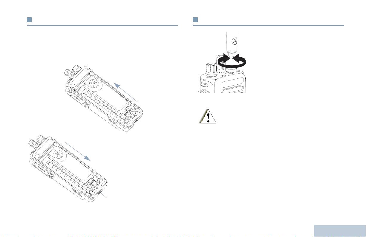
Установка аккумулятора
Установка антенны
Выровняйте аккумулятор относительно направляющих,
Подготовка радиостанции к работе
Выключив радиостанцию, установите
расположенных на задней стороне корпуса радиостанции.
антенну в соответствующее гнездо и
Твердым нажатием передвиньте аккумулятор вверх до
поверните по часовой стрелке
защелкивания фиксатора. Переведите фиксатор аккумулятора
в запертое положение.
Чтобы снять антенну, поверните ее
против часовой стрелки.
Чтобы извлечь
аккумулятор:
выключите
радиостанцию;
отоприте и
удерживайте
фиксатор
аккумулятора;
передвиньте
аккумулятор вниз и
снимите его с
направляющих.
3
Русский
Фиксатор
аккумулятора
Если антенну потребуется заменить, во избежание
повреждения радиостанции, используйте только
антенны MOTOTRBO.
Осторожно!
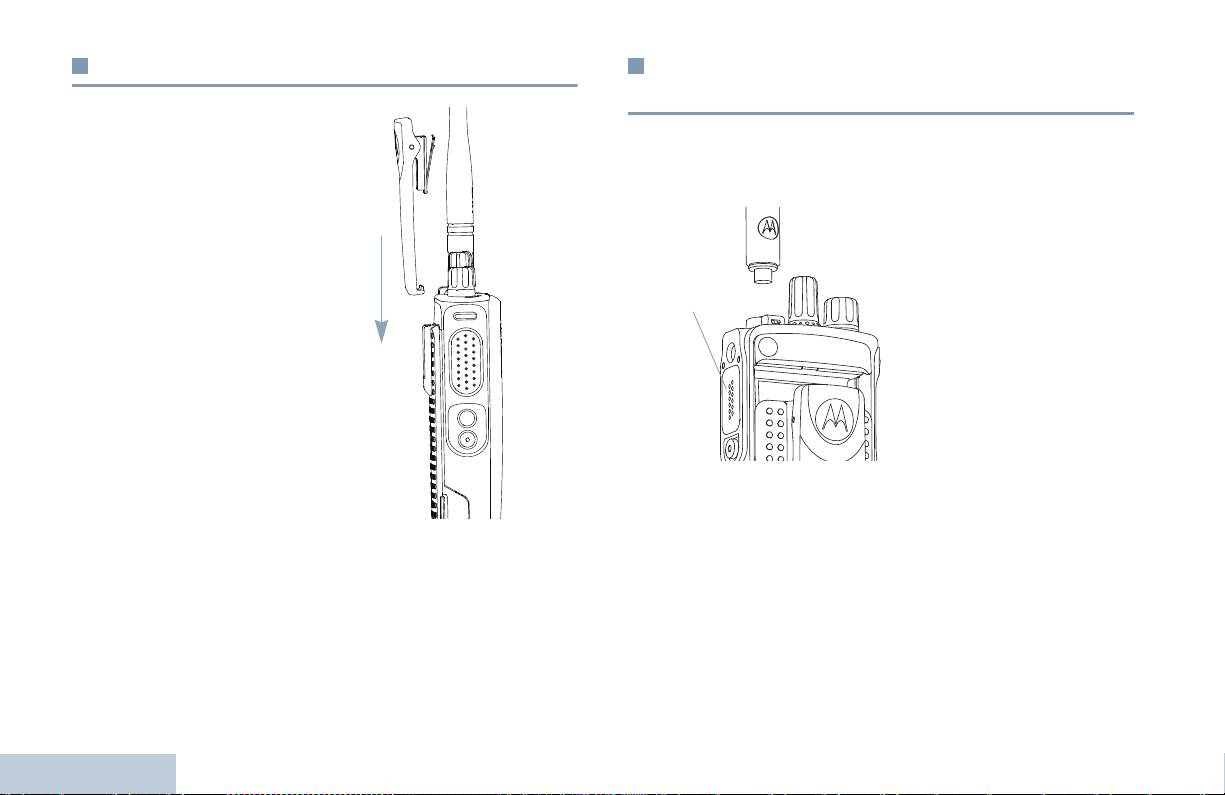
Установка поясного зажима
Установка крышки универсального
разъема (пылезащитной крышки)
Совместите направляющие
Универсальный разъем находится на корпусе радиостанции со
на поясном зажиме с
стороны антенны. Он предназначен для подключения к
направляющими
радиостанции аксессуаров MOTOTRBO.
аккумулятора и нажмите на
Вставьте загнутый конец
поясной зажим сверху вниз до
крышки в пазы над
щелчка.
универсальным разъемом.
Нажмите на крышку сверху
Чтобы снять зажим,
вниз, чтобы нижняя лапка
отожмите язычок зажима
правильно вошла в
для крепления на ремне от
РЧ-разъем.
аккумулятора. Это удобно
Закрепите крышку разъема на
делать ключом. Чтобы
корпусе радиостанции,
снять поясной зажим,
повернув винт по часовой
отожмите его лапку от
стрелке.
аккумулятора с помощью
ключа, затем передвиньте
Чтобы снять
крышку
зажим вверх до
универсального разъема, нажмите на крышку сверху вниз и
отсоединения
от
поверните винт против часовой стрелки.
радиостанции.
Когда универсальный разъем не используется, он должен быть
закрыт пылезащитной крышкой.
Подготовка радиостанции к работе
4
Русский
Универсальный
разъем

Включение питания радиостанции
Регулировка громкости
Подготовка радиостанции к работе
Поверните ручку Вкл./
Чтобы увеличить громкость, поверните ручку Вкл./Выкл./
Выкл./Громкость по
Громкость по часовой стрелке.
часовой стрелке до щелчка.
Непрерывным светом
загорится зеленый светодиод.
Звучит короткий тональный
сигнал, означающий, что
тестирование, выполняемое
при включении питания,
прошло успешно.
ПРИМЕЧАНИЕ:Если тоны/
оповещения
радиостанции
деактивированы, то
при включении
питания тон не
Чтобы уменьшить громкость, поверните эту ручку против
звучит (см. Активация и деактивация тонов/
часовой стрелки.
оповещений на стр. 37).
Если питание радиостанции не включается, проверьте
ПРИМЕЧАНИЕ: Радиостанцию можно запрограммировать на
аккумулятор. Убедитесь, что он заряжен и правильно
минимальный уровень громкости, чтобы звук
установлен. Если питание радиостанции по-прежнему не
нельзя было выключить полностью.
включается, обратитесь к вашему дилеру.
Дополнительную информацию узнайте у
дилера или администратора системы.
Чтобы выключить радиостанцию, поверните ручку против
часовой стрелки до щелчка.
5
Русский

Органы управления радиостанции
Ознакомьтесь со следующей информацией:
Органы управления радиостанции . . . . . . . . . . . . . . . . . . стр. 6
Программируемые кнопки . . . . . . . . . . . . . . . . . . . . . . . . . стр. 7
Тангента РТТ . . . . . . . . . . . . . . . . . . . . . . . . . . . . . . . . . . . . стр. 8
Переключение между конвенциональными
Аналоговым и Цифровым режимами . . . . . . . . . . . . . . стр. 9
Соединение IP-сайта . . . . . . . . . . . . . . . . . . . . . . . . . . . . стр. 10
Capacity Plus . . . . . . . . . . . . . . . . . . . . . . . . . . . . . . . . . . . стр. 10
Linked Capacity Plus . . . . . . . . . . . . . . . . . . . . . . . . . . . . . стр. 11
Органы управления радиостанции
Ручка выбора каналов
Ручка Вкл./Выкл./Громкость
Светодиодный индикатор
Боковая кнопка 1*
Тангента РТТ
Боковая кнопка 2*
Боковая кнопка 3*
Органы управления радиостанции
Микрофон
6
Русский
1
2
3
4
5
6
7
8
Динамик
Универсальный аксессуарный разъем
Экстренная кнопка*
Антенна
* Эти кнопки являются программируемыми.
1
12
2
11
10
3
4
9
5
8
6
7
9
10
11
12

Голосовое объявление канала – проигрывание голосовых
Программируемые кнопки
сообщений зоны и канала для текущего канала. Эта функция не
действует, если деактивирована функция Голосовое объявление.
Программируемые кнопки могут быть запрограммированы
Органы управления радиостанции
дилером для быстрого доступа к определенным функциям
Экстренный режим – инициирование или отмена Экстренного
радиостанции и установленным каналам/группам каналов в
тревожного сигнала или вызова в зависимости от программных
зависимости от длительности нажатия кнопки:
настроек.
• Короткое нажатие – нажатие и быстрое отпускание кнопки.
Умное аудио вкл/выкл – включение и выключение функции
Умное аудио.
• Длительное нажатие – продолжительное нажатие
программируемой кнопки.
‡
Ручной сайт-роуминг*
– включение ручного поиска сайта.
• Удерживание – удерживание кнопки нажатой.
АРУ микрофона вкл/выкл – включение и выключение
ПРИМЕЧАНИЕ: Запрограммированная длительность нажатия
автоматической регулировки усиления (АРУ) встроенного
кнопки применима ко всем назначаемым
микрофона. Не действует во время работы в режиме Bluetooth.
функциям и настройкам, общим и
Мониторинг – проверка выбранного канала на наличие
специфическим для радиостанции. Hа стр. 27
активности.
в разделе Экстренный режим в разделе
‡
Удаление мешающего канала*
– временное удаление
смотрите информацию о
ненужного канала (кроме Выбранного канала) из списка
запрограммированной длительности нажатия
сканирования. Под Выбранным каналом понимается выбранная
Экстренной кнопки.
пользователем комбинация зона/канал, откуда инициируется
сканирование.
Назначаемые функции
TM
Вызов одним нажимом
– непосредственное выполнение
Переключатель Bluetooth
-аудио – перенаправление звука
на встроенный динамик радиостанции или на Bluetooth-
заданного частного группового вызова, отправление оповещения
аксессуар.
о вызове или быстрого текстового сообщения.
Соединение Bluetooth – инициация операции поиска и
Функция функциональной платы – активация и деактивация
соединения Bluetooth.
функции (функций) функциональной платы для соответствующих
каналов.
Отсоединение Bluetooth – прекращение всех существующих
Bluetooth-соединений радиостанции и Bluetooth-устройств.
Переадресация вызовов – включение и выключение
переадресации вызовов.
7
Русский
* Неприменимо в режиме Capacity Plus
‡
Не относится к режиму Linked Capacity Plus
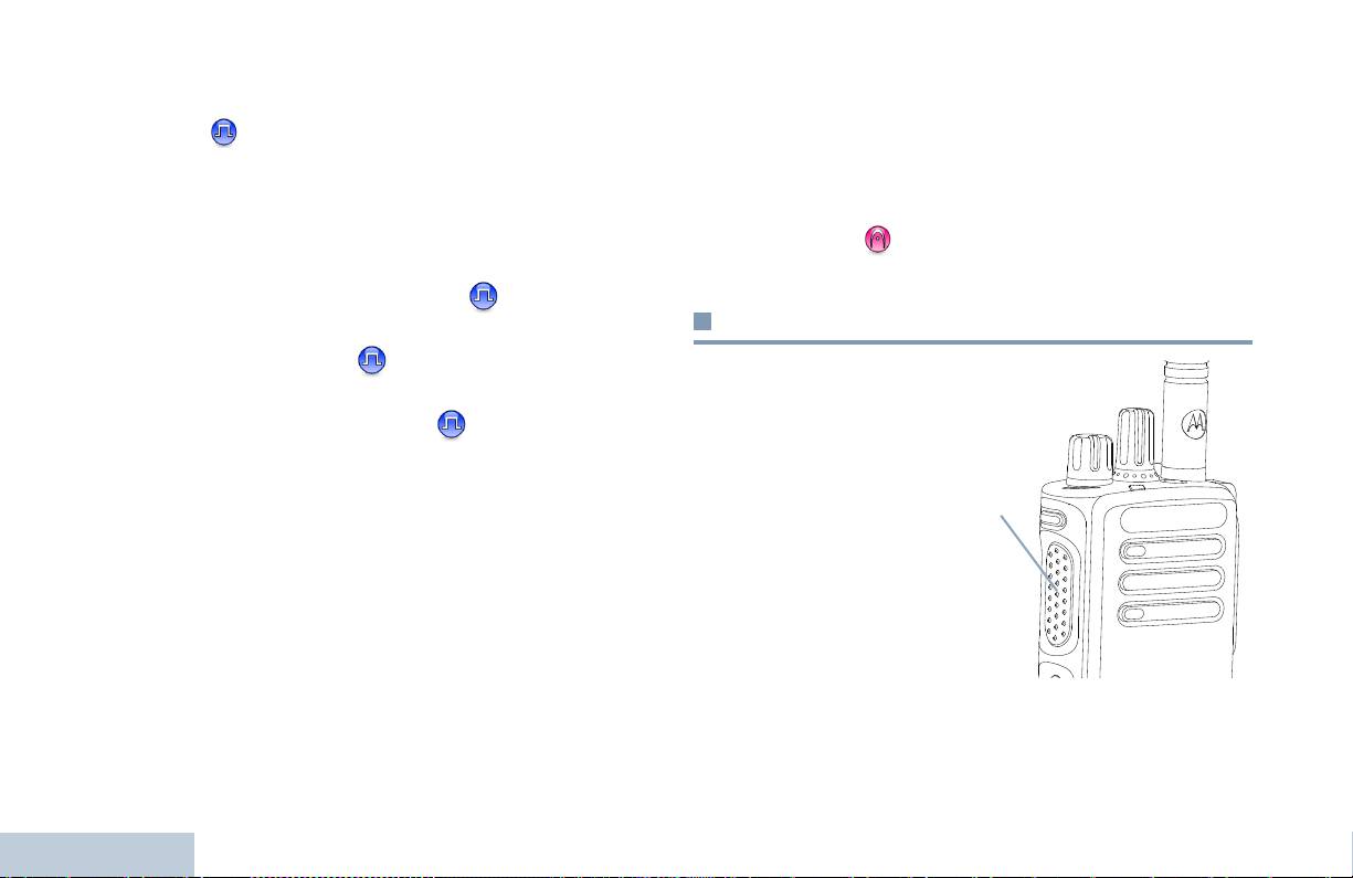
‡
Непрерывный мониторинг*
– мониторинг всего радиообмена
Назначаемые настройки/Дополнительные
на выбранном канале до выключения этой функции.
функции
Шифрование – активация и деактивация функции
Все тоны/оповещения – активация и деактивация всех тоновых
шифрования.
сигналов и оповещений.
‡
Ретранслятор/Прямая связь*
– переключение между режимом
Уровень мощности – переключение между высоким и низким
уровнями мощности передачи.
Ретрансляция и режимом Прямой связи с другой радиостанцией.
Шумоподавление
– переключение между высоким и
‡
Сканирование*
– Функция сканирования активирована.
нормальным уровнями шумоподавления.
Включение/выключение фиксации сайта* – включение и
выключение автоматического сайт-роуминга.
Тангента РТТ
Телеметрическое управление
– управление Выходным
Тангента РТТ (Push-To-
контактом местной или удаленной радиостанции.
Tal k) расположена на
Дистанционное прерывание передачи
– прекращение
боковой стороне
радиостанции и
прерываемого вызова для того, чтобы освободить канал.
выполняет две основные
Голосовое сообщение вкл/выкл – включение и выключение
функции:
функции Голосовое сообщение.
• Во время вызова
Голосовое управление передачей (VOX) – включение и
тангента РТТ переводит
выключение функции VOX.
радиостанцию в режим
передачи вашей речи
Зона – выбор зоны из списка зон.
на другие участвующие
в вызове радиостанции.
Заряд батареи – отображение заряда батареи с помощью
СИД-индикатора.
Для передачи нажмите
Органы управления радиостанции
тангенту РТТ и удерживайте ее. Для прослушивания отпустите
тангенту РТТ.
При нажатии тангенты РТТ включается микрофон.
8
Русский
* Неприменимо в режиме Capacity Plus
‡
Не относится к режиму Linked Capacity Plus
Тангента
PTT
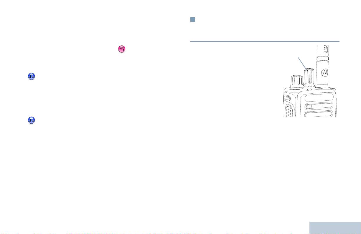
• Тангента РТТ также служит для выполнения новых вызовов (см
Переключение между
Выполнение радиовызова на стр. 18).
конвенциональными Аналоговым и
Органы управления радиостанции
В зависимости от программных настроек, если тон
Цифровым режимами
Разрешение разговора активирован или активирован
Каждый канал радиостанции
вспомогательный тон тангенты PTT , не начинайте
может быть настроен на
говорить, пока не закончится этот короткий оповещающий
работу в конвенциональном
тон.
Аналоговом или
конвенциональном
Если на вашей радиостанции активирована функция
Цифровом режиме.
Индикация свободного канала (программируется дилером),
Переключение между
то
в момент отпускания тангенты РТТ на вызываемой
аналоговыми и цифровыми
(принимающей ваш вызов) радиостанции вы услышите
каналами осуществляется
короткий тон, оповещающий о том, что канал свободен
Ручкой выбора каналов.
для вашей ответной передачи.
При переключении с
Цифрового на Аналоговый
Если вызов прерван (например, в случае получения
режим некоторые функции становятся недоступными.
экстренного вызова), то также прозвучит непрерывный
Некоторые функции радиостанции доступны как в Аналоговом,
тон запрета передачи, который означает, что нужно
отпустить кнопку тангенты.
так и в Цифровом режимах. Небольшие различия в
работе
каждой функции НЕ отражаются на качестве работы
радиостанции.
ПРИМЕЧАНИЕ: Радиостанция также переключается между
Цифровым и Аналоговым режимами во время
двухрежимного сканирования (см.
Сканирование на стр. 24).
9
Русский
Ручка выбора
каналов

В списке роуминга может быть не более 16 каналов (включая
Соединение IP-сайта
Выбранный канал).
Эта функция позволяет расширить конвенциональную связь
Пункты списка роуминга нельзя удалять или добавлять вручную.
радиостанции за пределы одного сайта и соединяться с разными
За соответствующей информацией обратитесь к вашему
дилеру
доступными сайтами посредством сети
или системному администратору.
Интернет-протокола (IP).
Когда радиостанция выходит из зоны доступности одного сайта и
Capacity Plus
попадает в зону доступности другого сайта, она соединяется с
ретранслятором нового сайта и может отправлять и принимать
Capacity Plus - это односайтовая транкинговая конфигурация
вызовы/данные. В
зависимости от настроек радиостанции эта
радиосистемы MOTOTRBO с использованием пула каналов,
процедура выполняется автоматически или вручную.
обеспечивающего связь между сотнями пользователей и
Если радиостанция настроена на автоматический поиск сайта, то
поддержку до 254 групп. Эта функция позволяет радиостанции
при слишком низкой силе сигнала текущего сайта или
эффективно использовать доступное количество
невозможности его обнаружить радиостанция сканирует все
запрограммированных каналов в режиме связи через
доступные сайты и фиксируется на базовой станции с самым
ретранслятор.
высоким значением RSSI (уровня принимаемого сигнала). Затем
При попытке доступа к функции, которая не относится к режиму
она фиксируется на ретрансляторе
с самым высоким значением
Capacity Plus с помощью нажатия программируемой кнопки,
силы принимаемого сигнала (RSSI).
прозвучит отрицательный
индикаторный тон.
При ручном поиске сайта радиостанция ищет следующий
В радиостанции также имеются функции, доступные в
доступный сайт из списка роуминга (не обязательно с самым
конвенциональном цифровом режиме, режимах Соединение
сильным сигналом) и фиксируется на нем.
IP-сайта, Capacity Plus и Linked Capacity Plus. Небольшие
ПРИМЕЧАНИЕ: Для каждого канала может быть активирована
различия в работе каждой функции НЕ отражаются на качестве
либо функция сканирования, либо функция
работы радиостанции.
роуминга, но не обе одновременно.
Дополнительную информацию о данной конфигурации узнавайте
Каналы, для которых активирована
эта функция, могут быть
у своего дилера или администратора системы.
включены в список роуминга. Во время автоматического роуминга
Органы управления радиостанции
радиостанция осуществляет поиск канала(ов) в списке роуминга,
чтобы определить самый лучший сайт.
10
Русский

Любой канал, на котором активирован режим Linked Capacity
Linked Capacity Plus
Plus, можно добавлять в конкретный список роуминга. Во время
автоматического роуминга радиостанция осуществляет поиск
Органы управления радиостанции
Linked Capacity Plus - это многосайтовая и многоканальная
этих каналов, чтобы определить самый лучший сайт.
транкинговая конфигурация системы радиостанций MOTOTRBO,
сочетающая в себе самой лучшее из конфигураций Capacity Plus
ПРИМЕЧАНИЕ: Пункты списка роуминга нельзя удалять или
и Соединение IP-сайта.
добавлять вручную. За соответствующей
информацией
обратитесь к вашему дилеру или
Linked Capacity Plus позволяет расширить транкинговую связь за
системному администратору.
пределы одного сайта и соединяться с разными доступными
сайтами посредством сети Интернет-протокола (IP). Также
Как и в случае режима Capacity Plus, в меню отсутствуют значки и
увеличивается емкость сети, благодаря эффективному
функции, не относящиеся к режиму Linked Capacity Plus. При
использованию всех доступных запрограммированных каналов,
попытке доступа к функции, которая не относится к режиму,
которые поддерживает каждый
из доступных сайтов.
Linked Capacity Plus с помощью нажатия программируемой
кнопки, прозвучит отрицательный индикаторный тон.
Когда радиостанция выходит из зоны доступности одного сайта и
попадает в зону доступности другого сайта, она соединяется с
Дополнительную информацию о данной конфигурации узнавайте
ретранслятором нового сайта и может отправлять и принимать
у своего дилера
или администратора системы.
вызовы/данные. В зависимости от настроек радиостанции эта
процедура выполняется автоматически или вручную.
Если радиостанция настроена на автоматический поиск сайта, то
при слишком низкой силе сигнала текущего сайта или
невозможности его обнаружить радиостанция сканирует все
доступные сайты и фиксируется на базовой станции с самым
высоким значением RSSI (уровня принимаемого сигнала). Затем
она фиксируется на ретрансляторе с самым высоким значением
силы принимаемого сигнала (RSSI).
При ручном поиске сайта радиостанция ищет следующий
доступный сайт из
списка роуминга (не обязательно с самым
сильным сигналом) и фиксируется на нем.
11
Русский
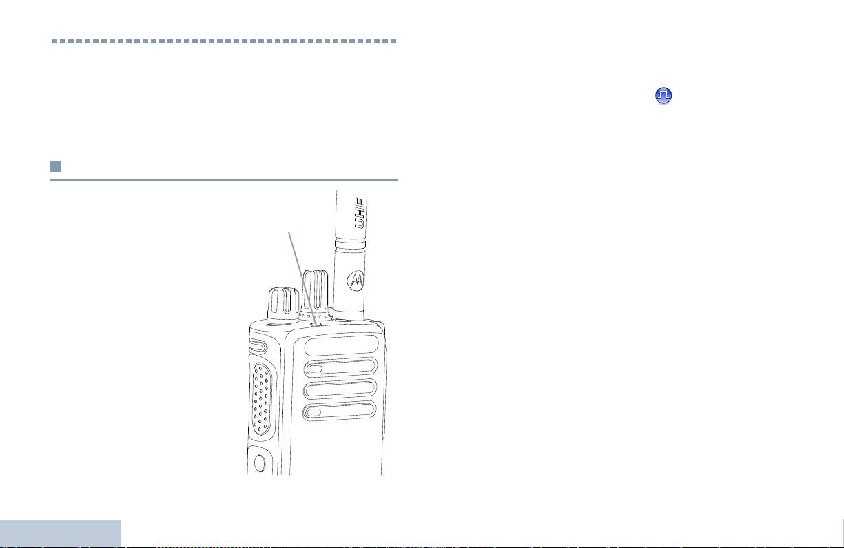
или данные без активации конфиденциальности или ведет
обнаружение активности в эфире.
Средства индикации радиостанции
Двойное мигание зеленым светом – Pадиостанция принимает
У радиостанции имеются следующие средства индикации:
вызов или данные со скремблированием
.
Светодиодный индикатор . . . . . . . . . . . . . . . . . . . . . . . . стр. 12
Непрерывный желтый – Радиостанция ведет мониторинг на
Звуковые тоны . . . . . . . . . . . . . . . . . . . . . . . . . . . . . . . . . стр. 13
цифровом конвенциональном канале. При нажатии клавиши
Индикаторные тоны . . . . . . . . . . . . . . . . . . . . . . . . . . . . . стр. 13
Заряд батареи этот сигнал означает хороший заряд
аккумулятора.
Светодиодный индикатор
Мигающий желтый – Радиостанция ведет сканирование или
принимает оповещение о вызове, или все локальные каналы
Визуальным средством
Linked Capacity Plus заняты.
оповещения о состоянии
Двойное мигание желтым светом – Соединение радиостанции
радиостанции является
с ретранслятором в Capacity Plus или Linked Capacity Plus
светодиодный индикатор.
прекращено, все
каналы Capacity Plus и Linked Capacity Plus в
Мигающий красный –
данный момент заняты, активирована функция Автоматический
Pадиостанция ведет передачу
роуминг, радиостанция активно ищет новый сайт. Этот сигнал
при низком заряде
также может означать, что радиостанция еще не отреагировала
аккумулятора, принимает
на оповещение о групповом вызове или заблокирована.
Экстренную передачу или не
прошла самотестирование при
ПРИМЕЧАНИЕ:В конвенциональном режиме светодиод мигает
включении питания.
зеленым, когда радиостанция обнаруживает
активность в эфире. В силу особенностей
Непрерывный зеленый –
цифрового протокола эта активность может
радиостанция включается или
влиять или не влиять на использование
ведет передачу. При нажатии
запрограммированного канала радиостанции.
кнопки Заряд батареи этот
сигнал также означает полный
В режимах Capacity Plus и Linked Capacity Plus
Средства индикации радиостанции
заряд аккумулятора.
обнаружение активности в эфире не
Мигающий
зеленый –
сопровождается светодиодной индикацией.
радиостанция принимает вызов
12
Русский
Светодиодный
индикатор
Индикаторные тоны
Звуковые тоны
Средства индикации радиостанции
Тоны служат для звукового оповещения о состоянии
Высокий тон Низкий тон
радиостанции или об ответе радиостанции на полученные
данные.
Положительный
индикаторный тон
Непрерывный тон
Непрерывный сигнал, который звучит,
пока не будет выключен пользователем.
Отрицательный
индикаторный тон
Периодический
Включается с периодичностью,
тон
определяемой настройками
радиостанции. Сигнал прекращается,
затем повторяется.
Повторяющийся
Одиночный сигнал, который повторяется
тон
до выключения пользователем.
Однократный тон
Включается только один раз на короткое
время, определяемое настройками
радиостанции.
13
Русский
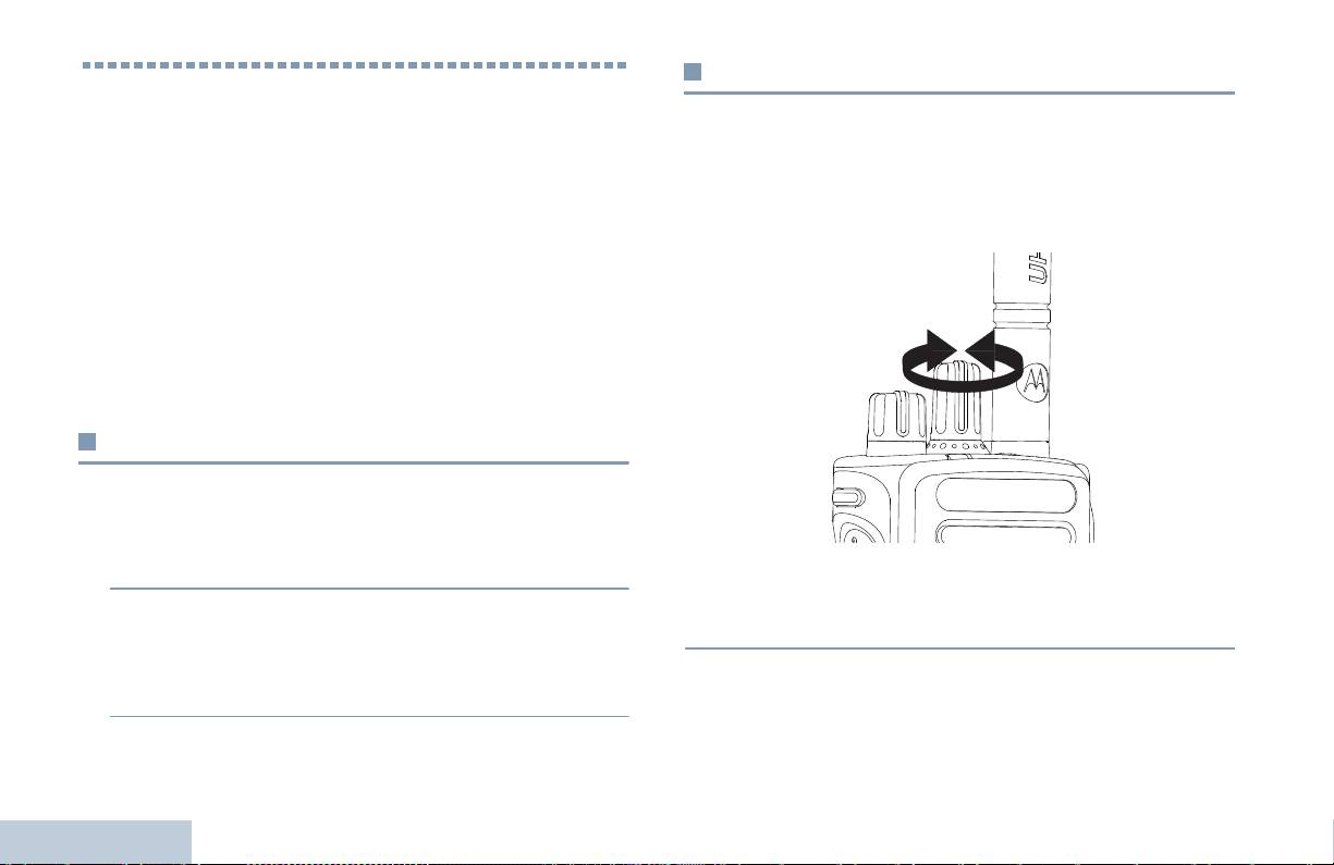
Выбор канала
Прием и выполнение вызовов
Прием и передача осуществляются на канале. В зависимости от
Освоив устройство радиостанции, можно приступать к
конфигурации радиостанции каждый канал можно
пользованию ей.
программировать по-разному, чтобы на нем были доступны
Ознакомьтесь со следующей информацией об основных
разные группы пользователей или разные функции. Выбрав
функциях управления вызовами:
нужную зону, выберите канал, который нужен для выполнения
Выбор зоны . . . . . . . . . . . . . . . . . . . . . . . . . . . . . . . . . . . . . .стр. 14
передачи или приема.
Выбор канала. . . . . . . . . . . . . . . . . . . . . . . . . . . . . . . . . . . . .стр. 14
Прием радиовызова. . . . . . . . . . . . . . . . . . . . . . . . . . . . . . . .стр. 15
Выполнение радиовызова. . . . . . . . . . . . . . . . . . . . . . . . . . .стр. 18
Прекращение радиовызова. . . . . . . . . . . . . . . . . . . . . . . . . .стр. 21
Прямая связь . . . . . . . . . . . . . . . . . . . . . . . . . . . . . . . . . . . . .стр. 21
Функции мониторинга . . . . . . . . . . . . . . . . . . . . . . . . . . . . . .стр. 22
Выбор зоны
Ваша радиостанция поддерживает до 32 каналов и до 2 зон, где в
зоне не более 16 каналов.
Процедура:
1 Нажмите запрограммированную кнопку Зона.
Процедура:
2 Звучит положительный тон, означающий, что радиостанция
Поворотом ручки выбора каналов выберите канал с активным
переключилась с Зоны 1 на Зону 2.
псевдонимом или идентификатором группы.
ИЛИ
Звучит отрицательный тон, означающий, что радиостанция
Прием и выполнение вызовов
переключилась с Зоны 2 на Зону 1.
14
Русский
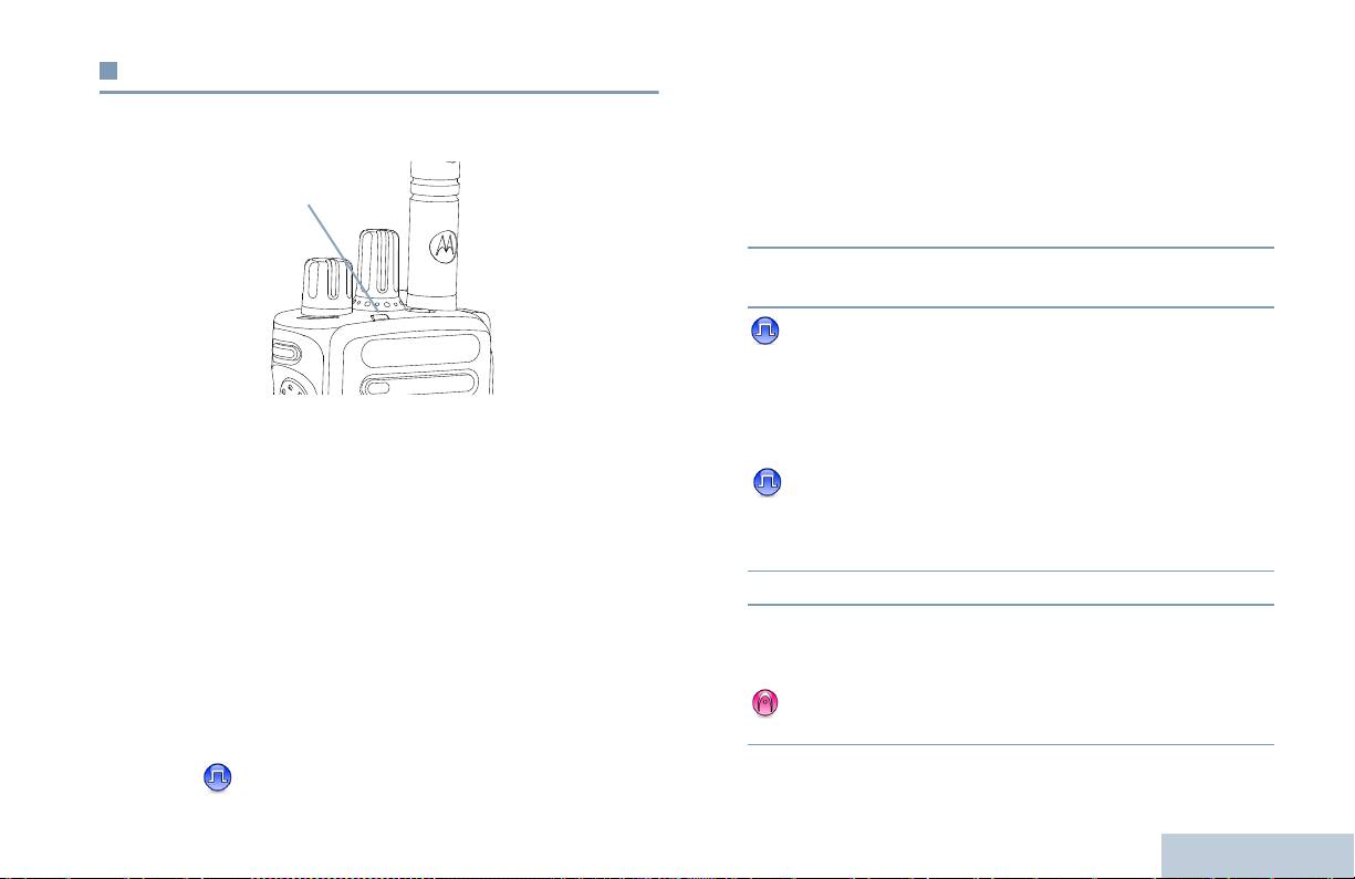
Прием радиовызова
Прием Группового вызова
После задания канала, ID абонента или ID группы радиостанция
Для приема вызова от группы пользователей необходимо, чтобы
Прием и выполнение вызовов
ваша радиостанция была сконфигурирована как член этой
готова к приему вызовов.
группы.
1 Светодиод начинает мигать зеленым. Шумоподавление
отключается, и звук входящего вызова звучит в динамике
радиостанции.
2 Чтобы принять вызов, держите радиостанцию вертикально в
2,5 - 5,0 см ото рта.
3 Если активирована функция Индикация свободного
канала, то в момент отпускания тангенты РТТ на передающей
радиостанции вы услышите короткий тон, оповещающий о
Светодиод непрерывно горит зеленым, когда радиостанция
том, что канал свободен для вашей ответной передачи.
ведет передачу, и мигает зеленым, когда радиостанция ведет
Нажмите кнопку тангенты PTT для ответа на вызов.
прием.
ИЛИ
ПРИМЕЧАНИЕ: Светодиодный индикатор горит непрерывным
Если активирована функция прерывания голосом,
зеленым светом, когда радиостанция ведет передачу, и
нажмите кнопку тангенты РТТ, чтобы прервать текущий вызов
мигает двойными вспышками зеленого цвета, когда
с передающей радиостанции и освободить канал для того,
радиостанция принимает вызов с активированной функцией
чтобы вы могли говорить/ответить.
конфиденциальности.
4 Светодиод начинает непрерывно гореть зеленым.
Для успешного дескремблирования скремблированных
5 Дождитесь окончания тона Разрешение разговора (если эта
вызовов Ключ конфиденциальности вашей радиостанции
ИЛИ ее Значение ключа и ID ключа (которые
функция активирована) и четко говорите в микрофон.
программируются дилером) должны совпадать с
ИЛИ
соответствующими параметрами передающей радиостанции.
Дождитесь окончания вспомогательного тона тангенты
PTT (если активирован) и четко говорите в микрофон.
Дополнительно об этом см. в разделе Шифрование на
стр. 31.
15
Русский
Светодиодный
индикатор

6 Для прослушивания отпустите тангенту РТТ.
4 Нажмите тангенту РТТ для ответа на вызов. Светодиод
начинает непрерывно гореть зеленым.
7 Если в течение заданного периода времени голос не звучит,
то вызов прекращается.
5 Дождитесь окончания тона Разрешение разговора (если эта
функция активирована) и четко говорите в микрофон.
О выполнении Группового вызова см. Выполнение Группового
6 Для прослушивания отпустите тангенту РТТ.
вызова на стр. 18.
7 Если в течение заданного периода времени голос не звучит,
то вызов прекращается.
Прием Частного вызова
8 Звучит короткий тон.
Частный вызов - это вызов одной радиостанции другой
радиостанцией.
О выполнении Частного вызова см. Выполнение Частного
Процедура:
вызова на стр. 19.
При поступлении Частного вызова:
1 Светодиод начинает мигать зеленым. Шумоподавление
отключается, и звук входящего вызова звучит в динамике
радиостанции.
2 Чтобы принять вызов, держите радиостанцию вертикально в
2,5 - 5,0 см ото рта.
3 Если активирована функция Индикация свободного канала, то
в момент отпускания тангенты РТТ на передающей
радиостанции вы услышите короткий тон, оповещающий о
том, что канал свободен для вашей ответной передачи.
ИЛИ
Если активирована функция прерывания голосом, нажмите
кнопку тангенты РТТ, чтобы прервать текущий вызов с
Прием и выполнение вызовов
передающей радиостанции и освободить канал для того,
чтобы вы могли говорить/ответить.
16
Русский
Прием Общего вызова
Прием выборочного вызова и ответ на него
Общий вызов - это вызов одной радиостанцией всех
Выборочный вызов - это вызов отдельной радиостанции,
Прием и выполнение вызовов
выполняемый с другой отдельной радиостанции. Это частный
радиостанций, работающих на данном канале. Его назначение -
вызов в аналоговой системе.
важные объявления, требующие особого внимания
пользователей.
Процедура:
Если поступил выборочный вызов:
Процедура:
1 Светодиодный индикатор мигает зеленым цветом.
При поступлении Общего вызова:
2 Держите радиостанцию вертикально на расстоянии
1 Светодиод начинает мигать зеленым. Шумоподавление
2,5 - 5,0 см ото рта.
Шумоподавление отключается, и звук
отключается, и звук входящего вызова звучит в динамике
входящего вызова звучит в динамике радиостанции.
радиостанции.
3 Если активирована функция индикации свободного канала, то
2 Если в течение заданного периода времени не звучит голоса,
как только в передающей радиостанции будет отпущена
общий вызов прекращается. Общий вызов заканчивается без
клавиша тангенты PTT , раздастся краткий тон оповещения,
установленного периода ожидания.
показывающий, что канал свободен для ответа.
Если активирована функция Индикация свободного
4 Нажмите кнопку тангенты PTT для ответа на вызов.
Непрерывным светом загорится зеленый светодиод.
канала, то в момент отпускания тангенты РТТ на передающей
радиостанции вы услышите короткий тон, оповещающий о
5 Подождите окончания тона разрешения разговора (если
том, что канал свободен.
активирован) и ясным голосом говорите в микрофон.
6 Отпустите кнопку тангенты PTT, чтобы слушать.
Ответ на Общий вызов не предусмотрен.
7 Если в течение заданного периода времени не звучит голоса,
ПРИМЕЧАНИЕ: Радиостанция прекратит прием Общего вызова,
связь прекращается.
если при поступлении вызова переключиться
на другой канал.
8 Зазвучит короткий тон.
Во время Общего вызова вы не сможете
пользоваться функциями
Информацию о том, как выполнять Частный вызов, см. в
запрограммированных кнопок до окончания
разделе
Выполнение выборочного вызова на стр. 19.
вызова.
17
Русский
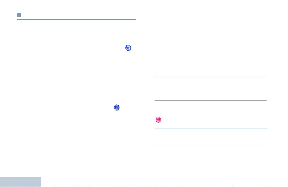
Выполнение радиовызова
Выполнение вызова с помощью Ручки выбора
каналов
Выбрав канал, можно выбрать псевдоним или идентификатор
Выполнение Группового вызова
абонента, псевдоним или идентификатор группы с помощью
следующей функции:
Для выполнения вызова группы пользователей необходимо,
чтобы ваша радиостанция была сконфигурирована как член этой
• Ручку выбора каналов
группы.
• Запрограммированная кнопка Вызова одним нажимом
Процедура:
ПРИМЕЧАНИЕ: Для того, чтобы делать конфиденциальную
1 Выберите канал с активным псевдонимом или
передачу, в вашей радиостанции должна быть
идентификатором группы. См. Выбор канала на стр. 14.
ИЛИ
активирована функция Конфиденциальность.
Нажмите запрограммированную кнопку Вызов одним
Расшифровать передачу могут только
нажимом.
радиостанции-получатели, имеющие тот же
ключ конфиденциальность ИЛИ то же
2 Держите радиостанцию вертикально на расстоянии
значение ключа и идентификатор ключа, что и
2,5 - 5,0 см ото рта.
в вашей радиостанции.
3 Нажмите тангенту РТТ для выполнения вызова. Светодиод
начинает непрерывно гореть зеленым.
Дополнительную информацию смотрите в
4 Дождитесь окончания тона Разрешение разговора (если эта
разделе Шифрование на стр. 31.
функция активирована) и четко говорите в микрофон.
ИЛИ
Функция Вызов одним нажимом позволяет
Дождитесь окончания вспомогательного тона тангенты
быстро выполнять Групповой или Частный
PTT (если активирован) и четко говорите в микрофон.
вызов по заданному ID. Для этой функции
можно отвести короткое или длительное
5 Для прослушивания отпустите тангенту РТТ. При ответе
нажатие программируемой кнопки.
вызываемой радиостанции светодиод начинает мигать
зеленым.
ТОЛЬКО один идентификатор можно
запрограммировать для кнопки Вызов одним
6 Если активирована функция Индикация свободного канала, то
Прием и выполнение вызовов
нажимом. Радиостанция имеет несколько
в момент отпускания тангенты РТТ на вызываемой
программируемых кнопок Вызов одним
радиостанции вы услышите короткий тон, оповещающий о
нажимом.
том, что канал свободен для вашей ответной передачи.
18
Русский

Для ответной передачи нажмите тангенту РТТ.
2 Держите радиостанцию вертикально на расстоянии
ИЛИ
2,5 - 5,0 см ото рта.
Если в течение заданного периода времени голос не звучит,
Прием и выполнение вызовов
3 Нажмите тангенту РТТ для выполнения вызова. Светодиод
то вызов прекращается.
начинает непрерывно гореть зеленым.
4 Дождитесь окончания тона Разрешение разговора (если эта
Выполнение Частного вызова
функция активирована) и четко говорите в микрофон.
Радиостанция может принимать и/или отвечать на
5 Для прослушивания отпустите тангенту РТТ. При ответе
Частные вызовы, инициируемые соответствующим
вызываемой радиостанции светодиод начинает мигать
образом запрограммированными радиостанциями, но
зеленым.
чтобы выполнять Частные вызовы, она тоже нуждается в
6 Если активирована функция Индикация свободного канала, то
соответствующем программировании.
в момент отпускания тангенты РТТ на вызываемой
Есть два типа частного вызова. В первом типе перед
радиостанции вы услышите короткий тон, оповещающий о
выполнением вызова производится проверка присутствия
том, что канал свободен для вашей ответной передачи. Для
радиостанции, а во втором типе вызов выполняется сразу же.
ответной передачи нажмите тангенту РТТ.
Только один из
этих типов вызова может быть
ИЛИ
запрограммирован дилером для радиостанции.
Если в течение заданного периода времени голос не звучит,
Если эта функция не активирована, то при попытке выполнить
то вызов прекращается.
Частный вызов с помощью кнопки Вызов одним нажимом или
7 Звучит короткий тон.
Переключателя каналов звучит отрицательный индикаторный
тон.
Выполнение выборочного вызова
Для связи с отдельными радиостанциями используйте Быстрые
текстовые сообщения или Оповещения о вызове. Дополнительно
Как и в случае с частным вызовом, можно принимать выборочный
об этом см.
в разделах Работа с Текстовыми сообщениями
вызов, выполняемый авторизованной радиостанцией, и(или)
на стр. 30 и Функция Оповещение о вызове на стр. 26.
отвечать на него, однако для выполнения выборочного вызова ваша
Процедура:
радиостанция должна быть соответственным образом
запрограммирована.
1 выберите канал с активным псевдонимом или
идентификатором абонента. См. Выбор канала на стр. 14.
Процедура:
ИЛИ
1 Выберите канал с активным псевдонимом или
Нажмите запрограммированную кнопку Вызов одним
идентификатором группы. См. Выбор канала на стр. 14.
нажимом.
19
Русский

2 Держите радиостанцию вертикально на расстоянии
2 Держите радиостанцию вертикально на расстоянии
2,5 - 5,0 см ото рта.
2,5 - 5,0 см ото рта.
3 Нажмите тангенту РТТ для выполнения вызова.
3 Нажмите тангенту РТТ для выполнения вызова. Светодиод
Непрерывным светом загорится зеленый светодиод.
начинает непрерывно гореть зеленым.
4 Подождите окончания тона разрешения разговора (если
4 Дождитесь окончания тона Разрешение разговора (если эта
активирован) и ясным голосом говорите в микрофон.
функция активирована) и четко говорите в микрофон.
5 Для прослушивания отпустите тангенту РТТ. При ответе
ИЛИ
вызываемой радиостанции светодиод начинает мигать
Дождитесь окончания вспомогательного тона тангенты
зеленым.
PTT (если активирован) и четко говорите в микрофон.
6 Если активирована функция Индикация свободного канала, то
в момент отпускания тангенты РТТ на вызываемой
Ответ пользователей канала на Общий вызов не
радиостанции вы услышите короткий тон, оповещающий о
предусмотрен.
том, что канал свободен для вашей ответной передачи. Для
ответной передачи нажмите тангенту РТТ.
ИЛИ
Если в течение заданного периода времени голос не звучит,
то вызов прекращается.
7 Звучит короткий тон.
Выполнение Общего вызова
Эта функция позволяет вызывать всех пользователей,
работающих на данном канале.
Для использования этой функции радиостанция должна быть
соответствующим образом запрограммирована.
Процедура:
Прием и выполнение вызовов
1 выберите канал с псевдонимом или идентификатором
активной группы общего вызова. См. Выбор канала на
стр. 14.
20
Русский

Прямая связь
Прекращение радиовызова
Прием и выполнение вызовов
Функция "прямой связи" позволяет поддерживать связь, когда
Эта функция позволяет прекратить идущий Групповой или
ваш ретранслятор не работает или ваша радиостанция
Частный вызов, чтобы освободить канал для передачи.
находится за пределами радиуса действия ретранслятора, но в
Например, когда в радиостанции при случайном нажатии
зоне приема других радиостанций.
кнопки тангенты PTT получается "застрявший микрофон".
Ваша радиостанция должны быть запрограммирована так,
ПРИМЕЧАНИЕ: Эта функция доступна только в режимах
чтобы этой функцией можно было пользоваться.
Capacity Plus и Linked Capacity Plus.
Процедура:
Процедура:
Находясь на нужном канале:
1 Нажмите программируемую кнопку Ретранслятор/прямая
1 Нажмите запрограммированную кнопку Дистанционное
связь.
прерывание передачи.
2 Прозвучит положительный индикаторный тон, означающий,
2 Дождитесь подтверждения.
что в радиостанции включен режим прямой связи.
3 Радиостанция подаст положительный индикаторный тон,
ИЛИ
говорящий о том, что канал свободен.
Прозвучит отрицательный индикаторный тон, означающий,
ИЛИ
что в радиостанции включен режим ретранслятора.
Радиостанция подаст отрицательный индикаторный тон,
При выключении питания заданная настройка Прямой связи
говорящий о том, что радиостанция не может освободить
сохраняется.
канал.
Если радиостанция передает прерываемый вызов, который
прекращается с помощью этой функции, то пока вы не
отпустите кнопку тангенты PTT, будет звучать
отрицательный индикаторный тон. В прерываемой
радиостанции с дисплеем на дисплее появляется надпись
Вызов прерван.
21
Русский

Функции мониторинга
Непрерывный мониторинг
Функция Непрерывный мониторинг служит для непрерывной
проверки выбранного канала на наличие активности.
Мониторинг канала
ПРИМЕЧАНИЕ: Эта функция доступна только в режимах
Функция Мониторинг позволяет убедиться перед передачей,
Capacity Plus и Linked Capacity Plus.
что канал свободен.
Процедура:
ПРИМЕЧАНИЕ: Эта функция доступна только в режимах
Capacity Plus и Linked Capacity Plus.
1 Нажмите запрограммированную кнопку Непрерывный
мониторинг.
Процедура:
2 Звучит оповещающий тон, и светодиод начинает
1 Нажав и удерживая запрограммированную кнопку
непрерывно гореть желтым.
Мониторинг, прослушайте канал.
3 Нажмите запрограммированную кнопку Непрерывный
2 В зависимости от программных настроек радиостанции вы
мониторинг, чтобы выйти из режима Непрерывный
услышите либо активность, либо полную тишину.
мониторинг.
3 Когда вы услышите "белый шум" (т.е. канал будет
4 Звучит оповещающий тон, и светодиод выключается.
свободен), нажмите тангенту РТТ для передачи и отпустите
ее для прослушивания. Светодиод начинает непрерывно
гореть желтым.
Прием и выполнение вызовов
22
Русский

Списки сканирования
Продвинутые функции
Продвинутые функции
Для отдельных каналов и групп каналов можно назначать
Ознакомьтесь со следующей информацией о продвинутых
списки сканирования. Радиостанция следит за наличием
функциях вашей радиостанции:
переговоров на каналах путем циклического сканирования
Списки сканирования . . . . . . . . . . . . . . . . . . . . . . . . . . . . стр. 23
каналов/групп каналов в последовательности, определяемой
списком сканирования, соответствующим текущему каналу.
Сканирование . . . . . . . . . . . . . . . . . . . . . . . . . . . . . . . . . . стр. 24
Настройки сигналов оповещения о вызовах . . . . . . . . . стр. 26
Ваша радиостанция позволяет создавать до 250 списков
Функция Оповещение о вызове. . . . . . . . . . . . . . . . . . . . стр. 26
сканирования, каждый из которых может содержать до 16
пунктов. Каждый список сканирования может одновременно
Экстренный режим . . . . . . . . . . . . . . . . . . . . . . . . . . . . . . стр. 27
включать
и аналоговые, и цифровые каналы.
Работа с Текстовыми сообщениями . . . . . . . . . . . . . . . . стр. 30
Шифрование . . . . . . . . . . . . . . . . . . . . . . . . . . . . . . . . . . . стр. 31
ПРИМЕЧАНИЕ: Эта функция доступна только в режимах
Многосайтовые функции управления . . . . . . . . . . . . . . . стр. 32
Capacity Plus и Linked Capacity Plus.
Функция Одинокий работник . . . . . . . . . . . . . . . . . . . . . . стр. 33
Функции блокировки с паролем. . . . . . . . . . . . . . . . . . . . стр. 33
Bluetooth . . . . . . . . . . . . . . . . . . . . . . . . . . . . . . . . . . . . . . стр. 34
Дополнительные
функции . . . . . . . . . . . . . . . . . . . . . . . . стр. 36
23
Русский

Сканирование
Включение и выключение сканирования
Процедура:
При включении сканирования радиостанция начинает
1 Нажмите запрограммированную кнопку Сканирование.
циклически сканировать запрограммированный для текущего
ИЛИ
канала список сканирования на наличие переговоров.
С помощью Ручки выбора каналов выберите канал, для
Светодиод начинает мигать желтым.
которого активировано Автосканирование.
Если, находясь на цифровом канале во время двухрежимного
2 При включении сканирования светодиод начинает мигать
сканирования, ваша радиостанция "фиксируется" на
желтым, и звучит положительный тон.
аналоговом канале, то она автоматически переключается с
ИЛИ
Цифрового на Аналоговый режим до окончания вызова. Если
При выключении сканирования светодиод выключается, и
происходит обратное, то
выполняется аналогичная процедура.
звучит отрицательный тон.
Сканирование бывает двух типов:
• Полное сканирование каналов (Ручное): Радиостанция
Ответ на вызов во время сканирования
сканирует все каналы/группы каналов вашего списка
При выполнении сканирования радиостанция останавливается
сканирования. В зависимости от настроек радиостанция
на канале/группе каналов, где обнаруживает активность.
может автоматически начать сканирование с последнего
Радиостанция остается на этом канале в течение
сканированного "активного" канала/группы каналов или с
запрограммированного периода времени, называемого
канала, с которого инициировано сканирование.
"паузой" сканирования.
• Автосканирование (Автоматическое): Радиостанция
Процедура:
начинает сканирование автоматически при выборе вами
канала/группы каналов, для которых активировано
1 Держите радиостанцию вертикально на расстоянии
Автосканирование.
2,5 - 5,0 см ото рта.
ПРИМЕЧАНИЕ: Эта функция доступна только в режимах
Если активирована функция Индикация свободного
Capacity Plus и Linked Capacity Plus.
канала, то в момент отпускания тангенты РТТ на
передающей радиостанции вы услышите короткий тон,
оповещающий о том, что канал свободен для вашей
Продвинутые функции
ответной передачи.
24
Русский

2 Во время паузы нажмите тангенту РТТ. Светодиод начинает
Восстановление мешавшего канала
непрерывно гореть зеленым.
Процедура:
Продвинутые функции
3 Дождитесь окончания тона Разрешение разговора (если эта
Чтобы восстановить мешавший и удаленный канал, выполните
функция активирована) и четко говорите в микрофон.
одно из следующих действий:
ИЛИ
• Выключите и снова включите питание радиостанции, ИЛИ
Дождитесь окончания вспомогательного тона тангенты
PTT (если активирован) и четко говорите в микрофон.
• Выключите и снова включите сканирование с помощью
запрограммированной кнопки Сканирование, ИЛИ
4 Для прослушивания отпустите тангенту РТТ.
• Смените канал с помощью Ручки выбора каналов.
5 Если не ответить на вызов до окончания паузы, то
радиостанция начнет сканировать другие каналы/группы
каналов.
Многочастотное сканирование
Многочастотное сканирование обеспечивает широкую зону
Удаление мешающего канала
покрытия там, где несколько базовых станций передают
Если по какому-либо каналу ("мешающему" каналу) постоянно
идентичную информацию на разных аналоговых каналах.
поступают ненужные вызовы/шумы, то можно временно
Радиостанция сканирует аналоговые каналы разных базовых
удалить этот канал из списка сканирования.
станций и выбирает наиболее сильный принимаемый сигнал.
Эта функция не применима к каналу, являющемуся Выбранным
Определив самый сильный сигнал, радиостанция открывает
каналом.
динамик для передач с соответственной базовой станции.
Процедура:
СИД-индикатор мигает желтым цветом, и в
панели статуса
1 Если ваша радиостанция "зафиксировалась" на ненужном
появляется значок многочастотного сканирования.
или мешающем канале, то нажмите запрограммированную
Для того, чтобы ответить на передаваемый сигнал во время
кнопку Удаление мешающего канала и удерживайте ее,
многочастотного сканирования, следуйте тем же процедурам,
пока не услышите тон.
которые используются при
Ответ на вызов во время
2 Отпустите кнопку Удаление мешающего канала.
сканирования
на стр. 24.
Мешающий канал удаляется.
25
Русский

Настройки сигналов оповещения о
2 Нажмите тангенту РТТ в течение четырех (4) секунд после
поступления Оповещения о вызове, чтобы ответить на
вызовах
Частный вызов.
Тоны, оповещающие о поступающих Частных вызовах, можно
активировать и деактивировать (см. Активация и
Посылка Оповещения о вызове с помощью
деактивация тонов/оповещений на стр. 37).
кнопки Вызов одним нажимом
Функция Оповещение с нарастающей
Процедура:
громкостью
1 Нажмите запрограммированную кнопку Вызов одним
нажимом, чтобы отправить Оповещение о вызове абоненту
Радиостанция может быть запрограммирована дилером на
с предопределенным ID.
непрерывное оповещение пользователя, когда тот не отвечает
на вызов. Громкость тревожного сигнала постепенно
2 При посылке Оповещения о вызове светодиод начинает
автоматически повышается.
непрерывно гореть зеленым.
Эта функция называется Оповещением с нарастающей
3 При поступлении подтверждения получения Оповещения о
громкостью.
вызове звучат два коротких сигнала.
ИЛИ
Функция Оповещение о вызове
Если подтверждение получения Оповещения о вызове не
поступило, то звучит низкий тон.
Функция Оповещение о вызове позволяет оповестить
пользователя другой радиостанции о необходимости вызвать
вас, когда у него будет такая возможность. Эту функцию можно
вызвать с помощью программируемой кнопки Вызов одним
нажимом.
Прием Оповещения о вызове
Процедура:
Продвинутые функции
При поступлении Оповещения о вызове:
1 Звучит повторяющийся тон. Светодиод начинает мигать
желтым.
26
Русский

Тревожный сигнал каждого из трех типов может быть послан
Экстренный режим
как:
• Обычный – Передача тревожного сигнала сопровождается
Продвинутые функции
Экстренный тревожный сигнал служит для оповещения о
чрезвычайных обстоятельствах. Инициировать Экстренный
звуковой и/или визуальной индикацией.
тревожный сигнал можно в любой момент, в любом режиме и
• Скрытый – Радиостанция передает сигнал тревоги без
даже при наличии активности на текущем канале.
звуковой и визуальной индикации. Радиостанция принимает
Длительность нажатия запрограммированной Экстренной
вызовы без звука в динамике радиостанции до тех пор, пока
кнопки может установить дилер, кроме длительного нажатия,
не будет нажата тангента PTT для того, чтобы выполнить
которое аналогично для всех кнопок:
вызов.
• Короткое нажатие – от 0,05 секунды до 0,75 секунды
• Скрытый с голосовой передачей – Радиостанция передает
сигнал тревоги без звуковой и визуальной индикации, но
• Длительное нажатие – от 1,00 секунды до 3,75 секунды
входящие вызовы идут со звуком в динамике радиостанции.
Экстренная кнопка отведена для функции включения/
Программируемую Экстренную кнопку или Экстренный
выключения экстренного режима. Заданное действие
ножной выключатель можно настроить на посылку Экстренного
Экстренной кнопки узнавайте у дилера.
тревожного сигнала только одного из указанных выше типов.
Если короткое нажатие Экстренной кнопки отведено для
включения экстренного режима, то длительное нажатие
Посылка Экстренного тревожного сигнала
Экстренной кнопки отводится для выхода из экстренного
Отправление неголосового экстренного сигнала, приводящего к
режима.
экстренной индикации в группе радиостанций.
Если длительное нажатие Экстренной кнопки отведено для
Процедура:
включения экстренного режима, то короткое нажатие
1 Нажмите программируемую кнопку Включения
Экстренной кнопки отводится для выхода из экстренного
экстренного режима.
режима.
Ваша радиостанция позволяет посылать Экстренные
2 Светодиод начинает непрерывно гореть зеленым.
тревожные сигналы трех типов:
3 При поступлении подтверждения получения Экстренного
• Экстренный тревожный сигнал
тревожного сигнала звучит Экстренный тон. Светодиод
начинает мигать зеленым.
• Экстренный тревожный сигнал с вызовом
ИЛИ
Если, несмотря на все повторные попытки, подтверждение
• Экстренный тревожный сигнал с последующей голосовой
получения Экстренного тревожного сигнала не поступило,
передачей
то звучит низкий тон.
27
Русский
4 Радиостанция выходит из режима Экстренный тревожный
7 Для прослушивания отпустите тангенту РТТ.
сигнал.
8 Когда канал освободится для ответа, прозвучит короткий
Если радиостанция настроена на скрытую посылку
тон
( , если активирована функция индикации
тревожного сигнала, то звуковая и визуальная индикация в
Экстренном режиме отсутствует.
свободного канала). Нажмите кнопку тангенты PTT, чтобы
ответить.
Посылка Экстренного тревожного сигнала с
ИЛИ
вызовом
По окончании своего вызова нажмите кнопку Выключения
экстренного режима, чтобы выйти из экстренного режима.
Отправление экстренного сигнала на группу радиостанций.
Когда радиостанция в группе подтвердит этот сигнал, группа
Если в радиостанции установлен скрытый режим, то
радиостанций сможет поддерживать связь на
звуковые и визуальные индикаторы не будут появляться во
запрограммированном экстренном канале.
время экстренного режима, и принимаемые вызовы не будут
идти на динамик радиостанции до тех пор, пока вы не
Процедура:
нажмете кнопку тангенты PTT, чтобы инициировать вызов.
1 Нажмите программируемую кнопку Включения
экстренного режима.
Если в радиостанции установлен
скрытый режим с
голосовой связью, то звуковые и визуальные индикаторы не
2 Светодиод начинает непрерывно гореть зеленым.
будут появляться во время экстренного режима, а
3 При поступлении подтверждения получения Экстренного
принимаемые вызовы будут идти на динамик радиостанции.
тревожного сигнала звучит Экстренный тон. Светодиод
Индикация появляется только после нажатия вами
начинает мигать зеленым.
тангенты РТТ для инициирования вызова или ответа на
4 Держите радиостанцию вертикально на расстоянии
вызов.
2,5 - 5,0 см ото рта.
Посылка Экстренного тревожного сигнала с
5 Нажмите тангенту РТТ для выполнения вызова. Светодиод
начинает непрерывно гореть зеленым.
последующей голосовой передачей
6 Дождитесь окончания тона Разрешение разговора (если эта
Отправление экстренного сигнала на группу радиостанций.
функция активирована) и четко говорите в микрофон.
Микрофон радиостанции активируется автоматически,
Продвинутые функции
ИЛИ
позволяя осуществлять связь с группой радиостанций без
Дождитесь окончания вспомогательного тона тангенты
нажатия кнопки тангенты PTT.
PTT (если активирован) и четко говорите в микрофон.
Этот режим работы микрофона называется "горячий
микрофон".
28
Русский

Если в радиостанции активирован режим экстренного цикла, то
4 Радиостанция автоматически прекращает передачу: когда
повторы "горячего микрофона" и приема делаются в течение
истекает заданный период цикла "горячего микрофона" и
заданного периода.
приема вызовов, если активирован режим экстренного цикла.
Продвинутые функции
ИЛИ
ПРИМЕЧАНИЕ: В режиме экстренного цикла принимаемые
когда истекает длительность действия "горячего микрофона",
вызовы звучат в динамике радиостанции.
если режим экстренного цикла выключен.
Если кнопка тангенты PTT нажата во время
5 Чтобы продолжить передачу, нажмите тангенту РТТ.
запрограммированного периода приема, прозвучит тон запрета,
ИЛИ
который означает, что нужно отпустить кнопку тангенты PTT.
Нажмите запрограммированную клавишу Отключение
Радиостанция игнорирует нажатие кнопки тангенты PTT и
экстренного режима, чтобы выйти из экстренного режима.
остается в экстренном режиме.
Если в радиостанции установлен скрытый режим, то
ПРИМЕЧАНИЕ: Если нажать тангенту PTT в режиме "горячего
звуковые и визуальные индикаторы не будут появляться во
микрофона" и удерживать ее нажатой после
время экстренного режима, а принимаемые вызовы не будут
того, как период "горячего микрофона" истек,
идти на динамик радиостанции до тех пор, пока не истечет
то радиостанция продолжит передачу, пока вы
запрограммированный период передачи в режиме "горячего
не отпустите тангенту PTT.
микрофона", и вы не нажмете
кнопку тангенты PTT.
Процедура:
Если в радиостанции установлен скрытый режим с
1 Нажмите программируемую кнопку Включения экстренного
голосовой связью, то звуковых и визуальных индикаторов при
режима.
осуществлении вызова через "горячий микрофон" во время
2 Светодиод начинает непрерывно гореть зеленым.
экстренного режима появляться не будет, но звук будет
идти на динамик радиостанции, когда
3 После тона начинайте четко говорить в микрофон. В режиме
радиостанция-получатель ответит после истечения
"горячего микрофона" передача осуществляется
запрограммированного периода передачи в режиме "горячего
автоматически, без нажатия тангенты РТТ, пока не истечет
период "горячего микрофона".
микрофона".
Индикация появляется только после нажатия
При передаче светодиод начинает непрерывно гореть
вами тангенты РТТ.
зеленым.
ПРИМЕЧАНИЕ: Если подтверждения экстренного сигнала не
получено, то радиостанция не будет его
повторять и напрямую войдет в режим
"горячего микрофона".
29
Русский
ПРИМЕЧАНИЕ: Выход из Экстренного режима также
Возврат в Экстренный режим
происходит при выключении питания
ПРИМЕЧАНИЕ: Эта функция доступна только для
радиостанции. При последующем включении
радиостанции, посылающей экстренный
питания радиостанция не возвращается в
сигнал.
Экстренный режим.
Это может иметь место в двух случаях:
• Находясь в Экстренном режиме, вы переключились на другой
Работа с Текстовыми сообщениями
канал. Это приводит к выходу из Экстренного режима. Если на
новом канале активирован Экстренный тревожный сигнал, то
радиостанция возвращается в Экстренный режим.
Посылка Быстрого текстового сообщения
• Вы нажали программируемую кнопку Включения экстренного
режима во время инициации/передачи экстренного сигнала.
С помощью программируемой кнопки можно посылать
Радиостанция выходит из этого режима, затем возвращается в
Быстрые текстовые сообщения, заранее
Экстренный режим.
запрограммированные дилером.
Процедура:
Выход из Экстренного режима
1 Нажмите запрограммированную кнопку Вызов одним
ПРИМЕЧАНИЕ: Эта функция доступна только для
нажимом, чтобы отправить предопределенное быстрое
радиостанции, посылающей экстренный
текстовое сообщение абоненту с определенным ID.
сигнал.
2 Светодиод начинает непрерывно гореть зеленым.
Радиостанция выходит из Экстренного режима в каждом из
3 Звучат два коротких сигнала, означающие, что сообщение
следующих случаев:
успешно послано.
ИЛИ
• Если поступает подтверждение получения Экстренного
Звучит низкий тон, означающий, что сообщение послать не
тревожного сигнала (только при посылке Экстренного
удалось.
тревожного сигнала), ИЛИ
• Получена телеграмма выхода из экстренного режима ИЛИ
Продвинутые функции
• Если тревожный сигнал не прошел несмотря на все повторные
попытки, ИЛИ
• Нажата кнопка Выключения экстренного режима.
30
Русский

Если Ключ конфиденциальности ИЛИ Значение ключа и ID
Шифрование
ключа не совпадают, то при приеме скремблированных передач
пользователь радиостанции слышит искаженный сигнал
Продвинутые функции
Эта функция позволяет предотвратить несанкционированное
(в случае базовой конфиденциальности) или не слышит ничего
прослушивание радиообмена на канале с помощью
(в случае улучшенной конфиденциальности).
программно реализуемого шифрования (скремблирования).
Передача со скремблированием сопровождается непрерывным
В части сигналинга и идентификации пользователя передачи
зеленым сигналом светодиодного индикатора, а при приеме
не скремблируются.
скремблированных передач светодиод быстро мигает зеленым
.
Активация функции шифрования является обязательным
ПРИМЕЧАНИЕ: В некоторых моделях радиостанций функция
условием ведения передач со скремблированием на канале, но
шифрования может отсутствовать. За
для приема передач это не является обязательным. После
соответствующей информацией обратитесь к
активации функции шифрования на канале по
-прежнему можно
вашему дилеру или системному
принимать нескремблированные передачи.
администратору.
Ваша радиостанция поддерживает два типа
Процедура:
конфиденциальности:
Для активации или деактивации функции шифрования
• Базовая конфиденциальность
нажмите запрограммированную кнопку
• Улучшенная конфиденциальность
Для радиостанции можно назначить лишь ОДИН из этих двух
типов конфиденциальности.
Для успешного дескремблирования скремблированных
вызовов или данных ваша радиостанция должна быть
запрограммирована таким образом, чтобы ее Ключ
конфиденциальности (в случае базовой конфиденциальности)
ИЛИ ее Значение ключа и ID ключа (в случае улучшенной
конфиденциальности) совпадали с соответствующими
параметрами передающей радиостанции.
31
Русский

Многосайтовые функции
Выключение автоматического поиска сайта
Во время выполнения радиостанцией активного поиска нового
управления
сайта:
Процедура:
Эти функции применимы, когда текущий канал радиостанции
1 Нажмите запрограммированную кнопку
является частью конфигурации Соединения IP-сайта или
Включение/выключение фиксации сайта.
Linked Capacity Plus.
ПРИМЕЧАНИЕ: Информацию об этих конфигурациях см. в
2 Звучит тон, и светодиод выключается.
разделе Соединение IP-сайта на стр. 10 и
Linked Capacity Plus на стр. 11.
Включение ручного поиска сайта
Включение автоматического поиска сайта
Процедура:
ПРИМЕЧАНИЕ: Радиостанция выполняет поиск нового сайта,
1 Нажмите запрограммированную кнопку Ручной
только если сигнал текущего сайта слишком
сайт-роуминг.
слаб или радиостанции не удается его
2 Звучит тон, и светодиод начинает мигать зеленым.
обнаружить. При высоком значении RSSI
радиостанция остается на текущем сайте.
3 Звучит положительный тон, и светодиод выключается. Это
Процедура:
означает, что радиостанция зафиксировалась на сайте.
1 Нажмите запрограммированную кнопку
ИЛИ
Включение/выключение фиксации сайта.
Звучит отрицательный тон, и светодиод выключается. Это
означает, что радиостанции не удалось зафиксироваться на
2 Звучит тон.
сайте.
3 Когда радиостанция выполняет активный поиск нового
сайта, светодиод быстро мигает желтым. Когда
радиостанция фиксируется на сайте, светодиод
выключается.
Радиостанция также выполняет автоматический поиск
Продвинутые функции
сайта (сайт не зафиксирован) при нажатии кнопки
тангенты или во время передачи, если рабочий канал,
многосайтовый канал с прилагаемым списком роуминга
находится вне зоны досягаемости.
32
Русский

Функция Одинокий работник
Функции блокировки с паролем
Продвинутые функции
Эта функция обеспечивает подачу тревожного сигнала в
Активация этой функции позволяет пользоваться
случае отсутствия активности со стороны пользователя
радиостанцией после включения, если введен пароль.
радиостанции (нажатия любой кнопки или переключения
Наберите пароль ручкой выбора каналов и тремя боковыми
переключателя каналов) в течение заданного времени.
кнопками (см. Органы управления радиостанции на стр. 6):
По истечении таймера неактивности радиостанция
• Позиции с 1 по 9 ручки выбора каналов соответствуют
предупреждает пользователя звуковым сигналом.
знакам с 1 по 9, а позиция 10 соответствует знаку 0.
Если активность со стороны пользователя по-прежнему
• Боковые кнопки от 1 до 3 соответствуют знакам от 1 до 3.
отсутствует, то по истечении заданного "таймера напоминания"
радиостанция инициирует Экстренный
тревожный сигнал.
Доступ к радиостанции через пароль
Эта функция может быть настроена на посылку Экстренного
Процедура:
тревожного сигнала только одного из следующих типов:
Включите радиостанцию.
• Экстренный тревожный сигнал
1 Зазвучит непрерывный тон.
• Экстренный тревожный сигнал с вызовом
2 Ручкой выбора каналов выберите первый знак пароля.
• Экстренный тревожный сигнал с последующей голосовой
3 Наберите остальные три знака пароля нажатием боковой
передачей
кнопки 1, 2 или 3. При каждом нажатии боковой кнопки
будет звучать положительный тон.
Радиостанция остается в Экстренном режиме с возможностью
После того, как набран второй знак пароля, радиостанция
голосовой связи, пока она не будет выведена из этого режима.
не реагирует на смену положения ручки выбора каналов.
О способах выхода из Экстренного режима см. в разделе
4 После набора последнего знака четырехзначного пароля
Экстренный режим на стр. 27.
радиостанция автоматически проверяет действительность
ПРИМЕЧАНИЕ: Эта функция доступна только в
пароля.
радиостанциях, в которых она активирована.
Если пароль набран верно:
За соответствующей информацией обратитесь
Радиостанция продолжит включение. См.
Включение
к вашему дилеру или системному
питания радиостанции
на стр. 5.
администратору.
ИЛИ
Если пароль набран неверно:
Зазвучит непрерывный тон. Повторите этапы 1 и 3.
33
Русский

ИЛИ
Bluetooth
После третьего неверного пароля радиостанция входит в
заблокированное состояние. Прозвучит тон, и желтый
Эта функция позволяет использовать Bluetooth-устройство
светодиод замигает двойной вспышкой.
(аксессуар), соединив его посредством Bluetooth-связи с
радиостанцией. Радиостанция совместима, как с
Радиостанция становится заблокированной на 15 минут,
Bluetooth-устройствами Motorola, так и с устройствами,
реагируя только на команды ручки Вкл./Выкл./Регулировки
имеющимися в массовой продаже.
громкости.
Дальность связи Bluetooth составляет 10 метров при прямой
ПРИМЕЧАНИЕ: В заблокированном состоянии радиостанция
видимости. Линия связи между радиостанцией и
не принимает вызовы, в том числе и
Bluetooth-устройством не должна быть ничем заслонена.
экстренные вызовы.
Рекомендуется не оставлять радиостанцию и не
рассчитывать на
то, что Bluetooth-устройство будет надежно работать на
Разблокирование заблокированной
удалении.
радиостанции
На пределе зоны приема звук и тон голоса могут звучать
Процедура:
прерывисто или с искажениями. Чтобы улучшить качество звука,
Подождите 15 минут. Повторите Этапы с 1 по 4, указанные в
нужно просто восстановить радиосвязь, приблизив
разделе
Доступ к радиостанции через пароль на
Bluetooth-устройство к радиостанции (в пределах установленной
стр. 33.
10-метровой зоны приема). В радиусе 10 метров максимальная
ИЛИ
мощность функции Bluetooth в радиостанции
составляет 2,5 мВт
(4 дБм).
Включите радиостанцию, если вы ее выключили, когда она
была заблокирована:
Радиостанция может поддерживать до 3 одновременных
1 Прозвучит тон, и желтый светодиод замигает двойной
Bluetooth-соединений с Bluetooth-устройствами разных типов.
вспышкой.
Например, это могут быть гарнитура, сканер и пульт-тангента.
Несколько соединений с однотипными Bluetooth-устройствами
2 Подождите 15 минут. Повторите Этапы с 1 по 4, указанные в
установить нельзя.
разделе
Доступ к радиостанции через пароль на
Дополнительную информацию о функциональности
стр. 33.
Продвинутые функции
Bluetooth-устройства, смотрите в руководстве для пользователя
соответственного Bluetooth-устройства.
При включении радиостанция снова начинает отсчет 15
минут заблокированного состояния.
34
Русский

Обнаружение Bluetooth-устройства и
Отсоединение Bluetooth-устройства
соединение с ним
Процедура:
Продвинутые функции
Процедура:
1 Нажмите программируемую кнопку отсоединения
Включите Bluetooth-устройство и поставьте его в режим
Bluetooth.
сопряжения. Смотрите руководство для пользователя
соответственного Bluetooth-устройства.
2 После отсоединения прозвучит положительный
индикаторный тон.
1 Нажмите запрограммированную кнопку соединения
Bluetooth на радиостанции.
Перенаправление звука
2 Прозвучит тон, и светодиодный индикатор замигает желтым
цветом.
Звук можно направлять на встроенный динамик радиостанции
или на внешний Bluetooth-аксессуар.
3 Для выполнения сопряжения с Bluetooth-устройством могут
потребоваться дополнительные действия. Смотрите
Процедура:
руководство для пользователя соответственного Bluetooth-
1 Нажмите запрограммированную клавишу Переключатель
устройства.
Bluetooth-аудио.
4 После успешной операции прозвучит положительный
2 При смене канала аудио звучит тон.
индикаторный тон.
ИЛИ
Если операция не состоялась, прозвучит отрицательный
индикаторный тон.
Не выключайте Вluetooth-устройство во время обнаружения и
соединения, чтобы не отменить операцию.
Радиостанция соединяется с тем находящимся в зоне
доступности Bluetooth-устройством, сигнал которого наиболее
сильный, или с которым она была соединена до этого.
ПРИМЕЧАНИЕ: Для сопряжения с некоторыми устройствами в
радиостанции может понадобиться
запрограммировать пин-код. За дополнительной
информацией обращайтесь к дилеру.
35
Русский

Процедура:
Дополнительные функции
1 Нажмите запрограммированную кнопку Уровень
мощности.
Регулировка уровня шумоподавления
2 Звучит положительный тон, означающий, что радиостанция
Функция шумоподавления позволяет отфильтровывать
работает с низким уровнем мощности.
ненужные вызовы с низким уровнем сигнала и каналы с
ИЛИ
повышенным уровнем фонового шума. Уровень
Звучит отрицательный тон, означающий, что радиостанция
шумоподавления можно регулировать.
работает с высоким уровнем мощности.
Уровни шумоподавления: Нормальный используется по
умолчанию. Высокий позволяет отфильтровывать ненужные
Активация и деактивация функций
вызовы и/или фоновый шум. Однако при этом возможно
функциональной платы
отфильтровывание дальних вызовов.
На канале возможна поддержка до 6 функций функциональной
Процедура:
платы. За соответствующей информацией обратитесь к
1 Нажмите запрограммированную кнопку Шумоподавление.
вашему дилеру или системному администратору.
2 Звучит положительный тон, означающий, что радиостанция
Процедура:
работает с высоким уровнем шумоподавления.
Для активации функции (функций) функциональной платы
ИЛИ
нажмите запрограммированную кнопку Функция
Звучит отрицательный тон, означающий, что радиостанция
функциональной платы.
работает с нормальным уровнем шумоподавления.
Включение и выключение функции голосового
Регулировка уровня мощности
управления передачей (VOX)
Для каждого канала можно установить высокий или низкий
Эта функция позволяет инициировать вызовы на
уровень мощности передачи.
запрограммированном канале без помощи рук, голосом. При
Уровни мощности: Высокий позволяет поддерживать связь с
поступлении голосового сигнала на микрофон
радиостанциями, находящимися на значительном расстоянии
VOX-аксессуара радиостанция автоматически ведет передачу
от вас. Низкий обеспечивает связь с радиостанциями,
в течение запрограммированного периода времени.
Продвинутые функции
находящимися на небольшом расстоянии.
При нажатии тангенты РТТ во время работы радиостанции
функция VOX выключается. Чтобы снова включить функцию
VOX, выполните одно из следующих действий:
36
Русский

• Выключите и снова включите питание радиостанции, ИЛИ
Проверка уровня заряда аккумулятора
• Смените канал с помощью Ручки выбора каналов, ИЛИ
Эта функция позволяет проверить текущий уровень заряда
Продвинутые функции
• Выполните следующее
аккумулятора.
ПРИМЕЧАНИЕ: Включение и выключение этой функции
Настройки: Непрерывный желтый сигнал светодиодного
возможно только в радиостанциях, в которых
индикатора означает удовлетворительный уровень заряда.
она активирована. За соответствующей
Непрерывный зеленый сигнал означает полный заряд.
информацией обратитесь к вашему дилеру
См. также Светодиодный индикатор на стр. 12.
или системному администратору.
Процедура:
Процедура:
Нажмите запрограммированную кнопку Заряд аккумулятора.
Для включения или выключения функции VOX нажмите
Светодиодный индикатор покажет текущий уровень заряда
запрограммированную кнопку VOX.
аккумулятора.
Если активирован тон Разрешение разговора, то для
инициирования вызова используйте инициирующее слово.
Голосовое объявление
Дождитесь окончания тона
Разрешение разговора и четко
говорите в микрофон.
Эта функция позволяет радиостанции объявлять текущую зону
или канал, выбираемый пользователем, а также нажатие
программируемой клавиши. Пользователь может настраивать
Активация и деактивация тонов/оповещений
параметры объявлений. Такие объявления как правило полезны
Все тоны и оповещения радиостанции (за исключением
в случаях, когда условия затрудняют просмотр того, что
Экстренного тона) можно при необходимости активировать и
отображается на дисплее.
деактивировать.
Включайте и выключайте функцию голосового объявления
Процедура:
следующим образом.
1 Нажмите запрограммированную кнопку Все тоны/
Процедура:
оповещения.
Нажмите программируемую клавишу Голосовое объявление
.
2 Звучит положительный тон, означающий, что все тоны и
оповещения активированы.
ИЛИ
Звучит отрицательный тон, означающий, что все тоны и
оповещения деактивированы.
37
Русский

Умное аудио
Радиостанция автоматически регулирует громкость звука с
учетом наружного шума как от стационарных, так и от подвижных
источников. Эта функция действует только в режиме приема и не
влияет на передаваемый звук.
ПРИМЕЧАНИЕ: Данная функция не действует во время
работы в режиме Bluetooth.
Включайте и выключайте умное аудио следующим образом.
Процедура:
Включайте и выключайте Умное аудио нажатием
запрограммированной клавиши.
GPS
Глобальная система позиционирования (GPS) представляет
собой спутниковую систему навигации, определяющую точное
местоположение радиостанции.
Процедура:
Включайте и выключайте GPS нажатием запрограммированной
клавиши.
Продвинутые функции
38
Русский

Гарантия емкости
Гарантия на аккумуляторы и
Гарантия емкости гарантирует 80% номинальной емкости в
Гарантия на аккумуляторы и зарядные
зарядные устройства
течение гарантийного срока.
Никель-металл-гибридные (NiMH) и
12 месяцев
Гарантия качества изготовления
литий-ионные (Li-Ion) батареи
Гарантия качества изготовления охватывает дефекты
Аккумуляторы IMPRES, используемые
изготовления при условии нормального пользования и
исключительно с зарядными устройствами
18 месяцев
обслуживания.
IMPRES
Все батареи MOTOTRBO два (2) года
Зарядные устройства IMPRES
(одноместные и многоместные, без
два (2) года
дисплея)
Зарядные устройства IMPRES
один (1) год
(многоместные с дисплеем)
39
Русский

компанией MOTOROLA. MOTOROLA не берет на себя никаких
обязательств или ответственности в отношении дополнений к данной
Ограниченная гарантия
гарантии или модификаций данной гарантии, кроме как в случаях, когда
они выражены в письменной форме и подписаны должностным лицом
СРЕДСТВА СВЯЗИ MOTOROLA
компании MOTOROLA.
I. НА ЧТО РАСПРОСТРАНЯЕТСЯ И В ТЕЧЕНИЕ
MOTOROLA не гарантирует монтаж, техническое или сервисное
обслуживание Изделия, если такая гарантия не предусмотрена
КАКОГО СРОКА ДЕЙСТВУЕТ ДАННАЯ
отдельным соглашением, заключенным компанией MOTOROLA и
ГАРАНТИЯ:
конечным пользователем-покупателем.
MOTOROLA SOLUTIONS, INC. (далее - “MOTOROLA”) гарантирует
MOTOROLA не несет никакой ответственности за какое-либо
перечисленные ниже средства связи, произведенные компанией
дополнительное оборудование, которое предоставлено не компанией
MOTOROLA, (далее - "Изделия") в отношении дефектов материалов и
MOTOROLA, и которое подсоединено к Изделию или используется
изготовления при условии нормального использовании и эксплуатации
совместно с ним, а также за эксплуатацию Изделия вместе с каким-
в течение периода времени, начинающегося с даты покупки,
либо дополнительным оборудованием, и все такое оборудование ясно
следующим образом:
исключается из сферы действия данной гарантии. Каждая система, в
которой используются Изделия, своеобразна, и поэтому компания
Цифровые портативные
два (2) года
MOTOROLA в рамках данной гарантии отказывается от
радиостанции серии DP
ответственности за дальность действия, зону покрытия и действие
Аксессуары для изделий (кроме
системы в целом.
один (1) год
батарей и зарядных устройств)
II. ОБЩИЕ ПОЛОЖЕНИЯ:
MOTOROLA по своему усмотрению или отремонтирует Изделие
В данной в полной мере изложены обязанности компании MOTOROLA в
(с использованием новых или восстановленных деталей), или заменит
отношении Изделия. Ремонт, замена или возврат денежных средств на
его на новое или восстановленное Изделие, или выплатит стоимость
усмотрение компании MOTOROLA является эксклюзивной мерой.
покупки изделия в течение гарантийного срока, если Изделие
ДАННАЯ ГАРАНТИЯ ДАЕТСЯ ВЗАМЕН ВСЕХ ОСТАЛЬНЫХ ЯСНЫХ
возвращено в соответствии с условиями данной гарантии. На
ГАРАНТИЙ. ПОДРАЗУМЕВАЕМЫЕ ГАРАНТИИ, В ТОМ ЧИСЛЕ, СРЕДИ
заменяемые детали и платы распространяется оставшийся срок
ПРОЧЕГО, ГАРАНТИИ ПРИГОДНОСТИ К ПРОДАЖЕ И ГАРАНТИИ
действия соответственной первоначальной гарантии. Все замененные
СООТВЕТСТВИЯ КОНКРЕТНОМУ НАЗНАЧЕНИЮ, ОГРАНИЧЕНЫ
детали Изделия становятся собственностью компании MOTOROLA.
СРОКОМ ДАННОЙ ОГРАНИЧЕННОЙ ГАРАНТИИ. КОМПАНИЯ
Срок данной ясно выраженной ограниченной гарантии может быть
MOTOROLA НИ В КОЕМ СЛУЧАЕ НЕ НЕСЕТ ОТВЕТСТВЕННОСТИ ЗА
Ограниченная гарантия
продлен компанией MOTOROLA только в отношении первоначального
УЩЕРБ, ПРЕВЫШАЮЩИЙ ЦЕНУ ПОКУПКИ ИЗДЕЛИЯ, ЗА
конечного пользователя-покупателя, и гарантия не может быть
КАКОЕ-ЛИБО УПУЩЕННОЕ ПОЛЬЗОВАНИЕ, УПУЩЕННОЕ ВРЕМЯ,
переуступлена или передана какой-либо другой стороне. Данная
НЕУДОБСТВО, КОММЕРЧЕСКИЕ УБЫТКИ, УПУЩЕННУЮ ПРИБЫЛЬ
гарантия является полной гарантией на Изделие, изготовленное
ИЛИ ЭКОНОМИЮ, ЛЮБОЙ ИНОЙ СОПУТСТВУЮЩИЙ, ОСОБЫЙ ИЛИ
40
Русский

КОСВЕННЫЙ УЩЕРБ, ВЫТЕКАЮЩИЙ ИЗ ПРИМЕНЕНИЯ ИЛИ
B) Дефекты и повреждения в результате неверного использования,
НЕВОЗМОЖНОСТИ ПРИМЕНЕНИЯ ЭТОГО ИЗДЕЛИЯ, В ТОЙ МЕРЕ, В
инцидента, попадания воды или недосмотра.
КАКОЙ ТАКОЙ ОТКАЗ ОТ ОТВЕТСТВЕННОСТИ ВОЗМОЖЕН В
C)Дефекты или повреждения в результате неправильного
Ограниченная гарантия
СООТВЕТСТВИИ С ЗАКОНОДАТЕЛЬСТВОМ.
тестирования, эксплуатации, установки, изменений, модификаций
или корректировки.
III. ПРАВА, ПРЕДУСМОТРЕННЫЕ
D) Поломка или повреждение антенн, если не является прямым
ЗАКОНОДАТЕЛЬСТВОМ ШТАТОВ:
следствием дефектов материалов или изготовления.
E) Изделие, подвергающееся неутвержденному демонтажу,
В НЕКОТОРЫХ ШТАТАХ НЕ ДОПУСКАЕТСЯ ИСКЛЮЧЕНИЕ ИЛИ
модификации или ремонту (включая, среди прочего, добавление
ОГРАНИЧЕНИЕ ОТВЕТСТВЕННОСТИ ЗА КОСВЕННЫЙ ИЛИ
оборудования, поставляемого не компанией MOTOROLA , к
СОПУТСТВУЮЩИЙ УЩЕРБ В СООТВЕТСТВИИ СО СРОКОМ
Изделию), который отрицательно влияет на рабочие характеристики
ПОДРАЗУМЕВАЕМОЙ ГАРАНТИИ, И ВЫШЕУКАЗАННЫЕ
Изделия или искажает процесс нормального гарантийного осмотра и
ОГРАНИЧЕНИЯ И ИСКЛЮЧЕНИЯ МОГУТ НЕ ДЕЙСТВОВАТЬ.
тестирования Изделия в целях проверки действительности
Данная гарантия дает конкретные юридические права, и в зависимости
гарантийной претензии.
от штата могут также существовать и другие права.
F) Изделие, серийный номер которого удален или сделан
неразборчивым.
IV. КАК ПОЛУЧИТЬ ГАРАНТИЙНОЕ
G) Аккумуляторные батареи в тех случаях, когда
ОБСЛУЖИВАНИЕ:
(1) какое-либо из уплотнений корпуса аккумуляторной батареи
Для того, чтобы получить гарантийное обслуживание, вы должны
сломано или имеет признаки повреждения.
предоставить доказательство покупки (с указанием даты покупки и
(2) повреждение или дефект является результатом зарядки или
серийного номера Изделия), а также доставить или отправить Изделие,
использования аккумулятора в оборудовании или в системе,
оплатив транспортировку и страховку, в уполномоченный центр
отличной от того Изделия, для которого он предназначен.
гарантийного обслуживания. Компания MOTOROLA предоставит
H) Затраты на транспортировку до ремонтного центра.
гарантийное обслуживание в одном из своих уполномоченных центров
I) Изделие, которое в связи с нелегальным или неутвержденным
гарантийного обслуживания. Если вы сначала обратитесь в
изменением программного обеспечения/программы ПЗУ Изделия не
организацию, которая продала вам Изделие (т.е. к дилеру или
функционирует в соответствии с опубликованной спецификацией
провайдеру услуг связи), он сможет помочь организовать гарантийное
MOTOROLA или маркировкой сертификации FCC, действующей в
обслуживание.
отношении Изделия в то время, когда Изделие было изначально
отправлено для продажи компанией MOTOROLA.
V. НА ЧТО НЕ РАСПРОСТРАНЯЕТСЯ ДАННАЯ
J) Царапины или иные повреждения поверхностей Изделия, не
ГАРАНТИЯ:
влияющие на работу Изделия.
A) Дефекты или повреждения, являющиеся результатом
K) Обычный и нормальный износ.
ненормального и необычного применения Изделия.
41
Русский

VI. ПОЛОЖЕНИЯ О ПАТЕНТАХ И ПРОГРАММНОМ
Компания MOTOROLA не несет никакой ответственности в отношении
каких-либо исков о нарушении патентов, основанных на сочетании
ОБЕСПЕЧЕНИИ:
предоставляемого Изделия или деталей с программным обеспечением,
MOTOROLA за свой собственный счет будет вести защиту от любого
аппаратурой или устройствами, которые не предоставлены компанией
иска к конечному пользователю-покупателю в той мере, в какой он
MOTOROLA, а также компания MOTOROLA не несет никакой
основан на заявлении о том, что Изделие или его части нарушают
ответственности за использование дополнительного оборудования или
патент США, и компания MOTOROLA оплатит относящиеся к такому
программного обеспечения, которое не предоставлено компанией
заявлению издержки и компенсацию ущерба, которые будут
MOTOROLA, и которое присоединено к Изделию или применяется в
окончательно взысканы с конечного пользователя-покупателя в таком
связи с ним. Выше изложена вся ответственность компании
иске, однако защита и оплата обусловлены следующим:
MOTOROLA в отношении нарушений Изделием или его частями каких-
A) Этот покупатель уведомляет о таком иске компанию MOTOROLA
либо патентов.
незамедлительно и в письменной форме;
Законодательство США и других стран сохраняет за компанией
B) Компания MOTOROLA одна контролирует защиту по такому иску, а
MOTOROLA определенные эксклюзивные права в отношении
также все переговоры об урегулировании или компромиссе; а также
программного обеспечения MOTOROLA, защищенного авторским
C) если Изделие или его части станут, или по мнению компании
правом, например, эксклюзивные права на воспроизведение и
MOTOROLA имеют вероятность стать предметом иска о нарушении
распространение копий этого программного обеспечения MOTOROLA.
патента США, покупатель разрешит компании MOTOROLA, за ее
Программное обеспечение MOTOROLA разрешается использовать
счет обеспечить этому покупателю право продолжения применения
только в Изделии, в которое было изначально включено это
Изделия или его частей, заменит или модифицирует их так, чтобы
программное обеспечение, и это программное обеспечение в Изделии
они не нарушали патент, или предоставит этому покупателю кредит
нельзя никаким образом заменять, копировать, распространять,
за это Изделие или его части с учетом амортизации и согласится на
модифицировать или использовать для создания каких-либо его
их возврат. Амортизация за каждый год будет одинаковой в течение
производных. Любое иное использование, включая, среди прочего,
срока службы Изделия или его частей и определяется компанией
изменение, модификацию, воспроизведение, распространение или
MOTOROLA.
декомпиляция этого программного обеспечения MOTOROLA, равно как
использование прав в отношении этого программного обеспечения
MOTOROLA, запрещено. Не дается никакой лицензии,
подразумеваемой, презюмируемой или иной, в отношении патентных
прав или авторских прав компании MOTOROLA.
VII. РЕГУЛИРУЮЩЕЕ ПРАВО:
Ограниченная гарантия
Данная Гарантия регулируется законодательством штата
Иллинойс, США.
42
Русский

Примечания
43
.
Русский

7 . . . . . . . . . . . . . . . . . . . . . . . . . . . . .
7 . . . . . . . . . . . . . . . . .
8 . . . . . . . . . . . . .
8 . . . . . . . . . . . . . . . . . . . . . . . . . . . . . (PTT
MOTOTRBO
9 . . . . . . . . . . . . . . . . . . .
iv
10 . . . . . . . . . . . . . . . . . . . . . . . . . . . . . . . IP Site Connect
iv . . . . RF
iv
10 . . . . . . . . . . . . . . . . . . . . . . . . . . . . . . . . Capacity Plus
11 . . . . . . . . . . . . . . . . . . . . . . . Linked Capacity Plus
v
12
vi
12 . . . . . . . . . . . . . . . . . . . . . . . . . . . . . . . . . .LED
1
14
1 . . . . . . . . . . . . . . . . . . . . . . . . .
14 . . . . . . . . . . . . . . . . . . . . . . . . . . . . . . . . . .
1 . . . . . . . .
14 . . . . . . . . . . . . . . . . . . . . . . . . . . . . . . . . . . .
2
15 . . . . . . . . . . . . . . . . . . . . .
2 . . . . . . . . . . . . . . . . . . . . . . . . . . . . . . . . . .
15 . . . . . . . . . . . . . . . . . . . .
3 . . . . . . . . . . . . . . . . . . . . . . . . . . . . . . . . . .
16 . . . . . . . . . . . . . . . . . . .
3 . . . . . . . . . . . . . . . . . . . . . . . . . . . . . . . . . .
17 . . . . . . . . . . . . . . . . . . . . . . .
4 . . . . . . . . . . . . . . . . . . . . . . . . . . . . . . .
17 . . . . . . . . . . . . . . . . . . . . . All Call
4 . . . . . . . . . . . . . . . . .
18 . . . . . . . . . . . . . . . . . . . . . . . . . . . . . .
5 . . . . . . . . . . . . . . . . . . . . . . . . . . . . . .
18 . . . . . . . . . . . . . . . . .
5 . . . . . . . . . . . . . . . . . . . . . . . . . . . . . . . . . .
18 . . . . . . . . . . . . . . . . . . . . . . . . . . .
19 . . . . . . . . . . . . . . . . . . . . . . . . . .
6
19 . . . . . . . . . . . . . . . . . . . . . . . . . . .
6 . . . . . . . . . . . . . . . . . . . . . . . . . .
i
يبرـع

30 . . . . . . . . . . . . . . . . . . . . . . . . . .
20 . . . . . . . . . . . . . . . . . . . . . . . . . . .
30 . . . . . . . . . . . . . . . . . . . . . . . .
21 . . . . . . . . . . . . . . . . . . . . . . . . . . . .
31 . . . . . . . . . . . . . . . . . . . . . . . . . . . . . . . . .
21 . . . . . . . . . . . . . . . . . . . . . . .Talkaround
32 . . . . . . . . . . . . . . . . . . . . . .
22 . . . . . . . . . . . . . . . . . . . . . . . . . . . . . . . .
32 . . . . . . . . . . . . . . . . . . . . . . . .
22 . . . . . . . . . . . . . . . . . . . . . . . . . . . . . . . . .
32 . . . . . . . . . . . . . . . . . . . . . . .
22 . . . . . . . . . . . . . . . . . . . . . . . . . . . . . . . .
32 . . . . . . . . . . . . . . . . . . . . . . . . .
23
33 . . . . . . . . . . . . . . . . . . . . . . . . . . . . . . . .
23 . . . . . . . . . . . . . . . . . . . . . . . . . . . . . . . . . .
33 . . . . . . . . . . . . . . . . . . . . . . . . . .
24 . . . . . . . . . . . . . . . . . . . . . . . . . . . . . . . . . . . . . .
33 . . . . . . . . . . . . . . . . . .
24 . . . . . . . . . . . . . . . . . . . . . . . . . . . . .
34 . . . . . . . . . . . . . . . . . . . . . . . .
24 . . . . . . . . . . . . . . . . . . . . . .
34 . . . . . . . . . . . . . . . . . . . . . . . . . . . . . . . .
25 . . . . . . . . . . . . . . . . . . . . . . . . . . . . . .
35 . . . . . . . . . . . . . . . . . . . . . .
25 . . . . . . . . . . . . . . . . . . . . . . . . . . . . . .
35 . . . . . . . . . . . . . . . . . . . . . .
25 . . . . . . . . . . . . . . . . . . . . . . . . . . . . . . . . . . . . .
35 . . . . . . . . . . . . . . . . . . . . . . . . . . . .
26 . . . . . . . . . . . . . . . . . . . . . . . . . . . .
36 . . . . . . . . . . . . . . . . . . . . . . . . . . . . . . . . .
26 . . . . . . . . . . . . . . . . . . . . . . .
36 . . . . . . . . . . . . . . . . . . . . . . . . . .
26 . . . . . . . . . . . . . . . . . . . . . . . . . . . . .
36 . . . . . . . . . . . . . . . . . . . . . . . . . . . .
26 . . . . . . . . . . . . . . . . . . . . .
36 . . . . . . . .
26 . . . . . . . . . .
27 . . . . . . . . . . . . . . . . . . . . . . . . . . . . . . .
36 . . . . . . . . . . . . . . . . . . . . . . . (VOX
27 . . . . . . . . . . . . . . . . . . . . . . . . . . . .
37 . . . . . . . . . . . . .
28 . . . . . . . . . . . . . . . . . . . . . .
37 . . . . . . . . . . . . . . . . . . . . . . .
28 . . . . . . . . . . . . . . . . . . . . . . . . . .
37 . . . . . . . . . . . . . . . . . . . . . . . . . . . . . . . .
30 . . . . . . . . . . . . . . . . . . . . . . . . . .
38 . . . . . . . . . . . . . . . . . . . . . . . . . . . . . . .
30 . . . . . . . . . . . . . . . . . . . . . . . .
ii
يبرـع

38 . . . . . . . . . . . . . . . . . . . GPS
39
40
iii
يبرـع
Table of contents
-
-
-
-
-
- Q
- Q Q
- Q Q
- Q Q
-
- Q
-
- Q
- Q
- Q
-
-
- Q
-
- Q
-
- Q Q
- Q
- Q
- Q
- Q
- Q
- Q
-
- Q
- Q
- Q
- Q Q
- Q
-
- Q
-
-
-
-
