Bondioli&Pavesi 399CEE011_F: instruction
Class: Car Accessories
Type:
Manual for Bondioli&Pavesi 399CEE011_F

BONDIOLI & PAVESI S.p.A. - P.O.BOX 30/C
46029 SUZZARA (MN) - ITALIA
MADE IN ITALY
399CEE011/F
1
1
ROTATING DRIVE SHAFT
CONTACT CAN CAUSE DEATH
KEEP AWAY!
DO NOT OPERATE WITHOUT-
ALL DRIVELINE GUARDS, TRACTOR
AND EQUIPMENT SHIELDS IN PLACE
DRIVE SHAFT SECURELY
ATTACHED AT BOTH ENDS
DRIVE SHAFT GUARDS THAT TURN
FREELY ON DRIVE SHAFT
READING OPERATOR’S MANUAL
DO NOT USE PTO ADAPTORS
399141000
Cod 399JAP001
Cod 399141000
2
3
Cod 399CEE051
4
Cod 399143000
3
95
6 10
7 11
8 12
4
1713
14 18
15 19
16 20
5
2521
22 26
23
27
24 28
6
29 33
30 34
31 35
32 36
7
T CC
37
S
S
S
C
C
C
C
T
S S
1 oz. = 28,3 g
S1 S2 S4 S5 S6 H7 S8 H8 S9 SH S0
4 gr. 7 gr. 10 gr. 13 gr. 18 gr. 22 gr. 26 gr. 28 gr. 30 gr.
C
6 gr.
S
12 gr. 20 gr. 32 gr.
T
20 gr. 30 gr. 60 gr. 80 gr.
100 gr. 160 gr.
80°
5 gr. 6 gr. 7 gr. 8 gr.
50°
37
36g 16g
36g
SK
6g 6g
16g
1 oz. = 28,3 g
8
38
42
39
43
40 44
41 45
9
46
50
47
51
5248
49
53
10

54
58
55
59
56 60
57 61
11
62
66
63
67
64
68
65
69
12

70
74
71
75
72
76
73
77
13
78
82
79
83
80
84
81
85
14
86 87
88
89
15

ENG
TRANSLATION OF THE
ORIGINAL INSTRUCTIONS
ENGLISH
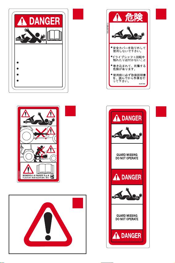
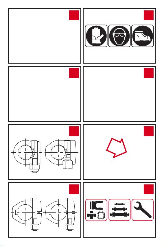
SAFETY LABELS
SHIELD TUBE LABEL COD. 399141000
1
SHIELD TUBE LABEL COD. 399JAP001
The operator must obey all labels and must maintain the proper shielding.
A high percentage of driveline injuries occur when safety shielding is missing or
not functioning properly.
For export reasons it may be displayed together with label 399CEE051 but this is
not necessary for the purpose of obtaining .
SHIELD TUBE LABEL COD. 399CEE051
2
Rotating driveline – contact can cause death. Keep away! Do not wear loo-
se clothing, jewelry, or hair that could become entangled with the driveline.
Do not operate without all driveline, tractor and implement shields in place. Dama-
ged or missing parts must be repaired or replaced before using the driveline.
Driveline must be securely attached at both ends. Driveline shields must turn freely
on driveline.
Disconnect PTO clutch, shut off tractor engine, and remove key before approaching
the implement. Keep all bystanders away from the implement while in operation.
Read this manual, and the operator’s manual for the implement, before using the
machine.
YOUR SAFETY DEPENDS UPON THIS INFORMATION.
DRIVE TUBE LABEL COD. 399143000
3
DANGER! Do not wear loose clothing, jewelry, or hair that could become
entangled with the driveline.
Contact with rotating parts could cause serious injury or death.
GUARD MISSING DO NOT OPERATE.
Do not operate without all driveline, tractor and implement shields in place.
Damaged or missing parts must be repaired or replaced before using the driveline.
SAFETY AND WORKING CONDITIONS
When using the implement and the driveline, do not exceed the speed or
4
power limits given by the operator’s manual.
Do not overload the implement or suddenly engage the PTO clutch.
Any torque limiter or clutch must be installed on the implement end of the driveline.
Use the implement only with the original driveline, which is compatible in length,
power capacity, torque limiters or overrunning clutches and shielding.
The driveline and its torque limiter or overrunning clutch are designed specically
for the implement, and should be used exclusively for this purpose.
Verify in the implement instruction handbook if the driveline requires a torque li-
miting or overrunning clutch. Standard drivelines, torque limiters and overrunning
–1
clutches are designed for speeds up to 1000 min
.
Check that the driveline can operete freely without interfering with the tractor or
implement. Contact with parts of the tractor (drawbar, tires, three point linkage)
damage the shield on the driveline.
Do not use tractors or implement hitching systems that interfere with the driveline
when the joint angles change. Do not use adapters or other components not ap-
proved by the implement manufacturer.
16

ENG
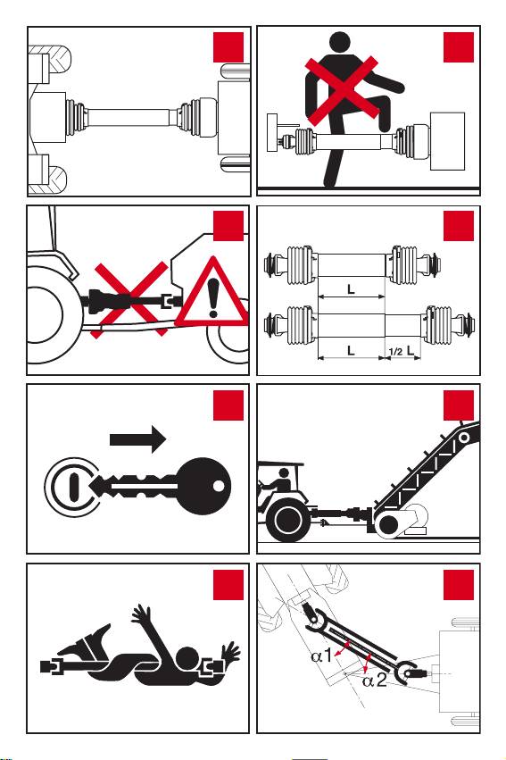
All rotating parts must be guarded. Contact with a rotating driveline can
5
cause death or serious injury. The tractor master shield, the driveline guards,
and the implement input connection shield form an interactive guarding system.
Ensure that all driveline, tractor, and implement shields are functional and
6
in place before operation. Damaged or missing parts must be replaced with
original equipment spare parts, correctly installed, before using the driveline.
Disengage the PTO, turn off the tractor engine, remove the key, and check
7
that all rotating parts have come to a standstill before approaching the im-
plement or performing maintenance work.
Do not approach, nor allow bystanders to come near the work zone or rota-
8
ting parts. Do not wear loose clothing, jewelry, hair, or anything which could
get caught in the machine.
Contact with rotating parts could cause serious injury or death.
Do not stand, lean, or otherwise come in contact with the driveline. Do not
9
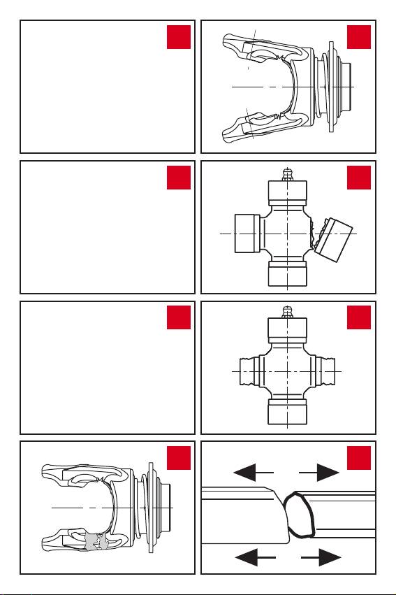
step over or go under the driveline.
Telescoping tubes should overlap by 1/2 of their length in normal operation
10
and they must overlap by at least 1/3 of their length in any operating condi-
tion. If greater telescoping capability is required, contact the implement dealer or
manufacturer. During maneuvers, when the driveline is not rotating, the telescoping
tubes must have a suitable overlap to maintain the tubes aligned and allow then to
slide propely.
Always hitch the tractor to STATIONARY MACHINERY (pumps, hoists, ge-
11
nerators, dryers, etc.) so that the prole tubes are not over-extended, and
chock the tractor wheels to prevent rolling.
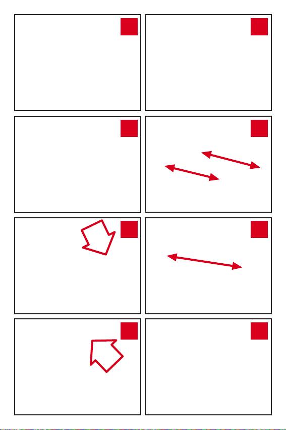
SINGLE CARDAN JOINTS
12
When operating, ensure that the joint angles are small and as equal as pos-
sible. The joint angles may vary widely during turns, but must never exceed 35°
under power or 45° during rotation. Disengage the PTO when the angle of the
joints becomes excessive or too unequal.
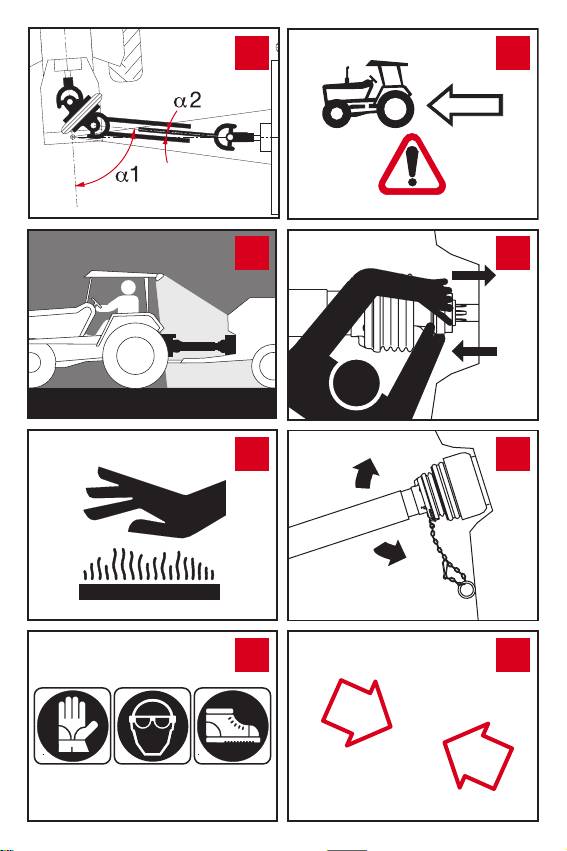
CONSTANT VELOCITY JOINTS
13
Constant velocity joints can allow large joint angles - up to 50°, 75° (SH
dimension) or 80° depending upon the type. These joint angles should only be
allowed for brief periods, for example during turning.
For drivelines with a constant velocity joint on the tractor side and a single cardan
joint on the implement side, the maximum recommended angles of the single joint
–1
–1
are 16° at 540 min
and 9° at 1000 min
to prevent irregular motion.
When used at night or in poor visibility, illuminate the driveline operating
14
area.
Friction clutches may become hot during use. Do not touch!
15
Keep the area around the friction clutch clear of any material which could
catch re and avoid prolonged slipping.
17

ENG
RATED POWER Pn and RATED TORQUE Mn
-1
-1
540 min
1000 min
Pn Mn Pn Mn
kW CV-HP-PS N∙m kW CV-HP-PS N∙m
S1 13 18 234 20 27 190
S2 21 28 364 31 42 295
S4 28 38 494 42 57 400
S5 37 50 651 55 75 527
S6 40 55 716 61 83 583
H7 51 70 911 78 106 745
S8 66 90 1171 100 136 956
H8 66 90 1171 100 136 956
S9 81 110 1431 122 166 1166
SH 97 132 1717 147 200 1405
S0 124 169 2199 187 254 1785
SK 180 254 3183 284 386 2712
INSTALLATION
Always wear adequate safety equipment when performing any maintenance
16
or repair work.
The tractor symbol on the shield indicates the tractor end of the driveline.
17
Torque limiters or overrunning clutches must be mounted at the implement
end.
Ensure that the driveline is securely attached to the tractor and the imple-
18
ment before operating.
Check that all bolts or nuts are properly torqued.
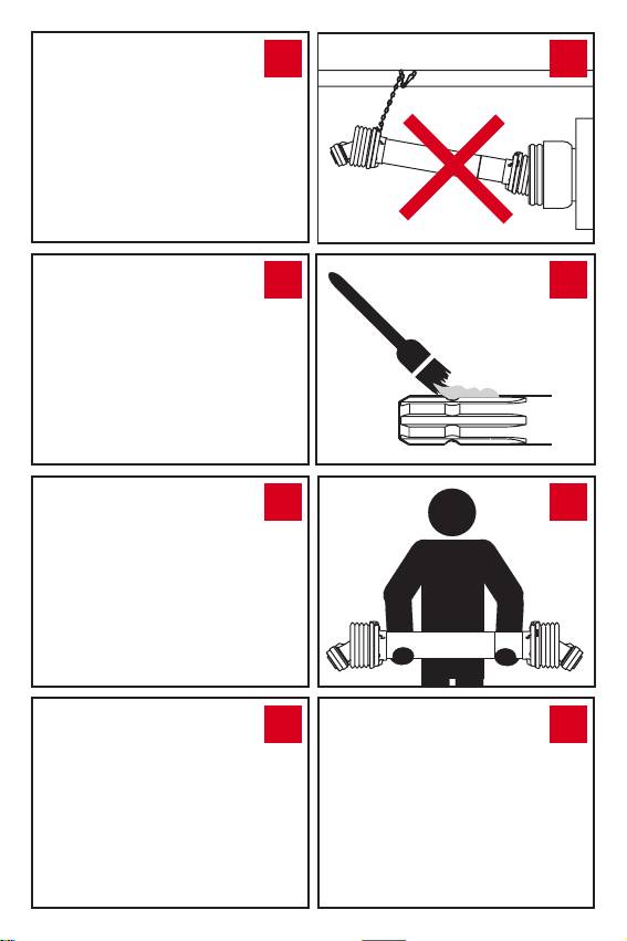
Attach the shield restraint chains, allowing sufcient slack for the driveline to
19
move during turns and operation.
Best results are achieved when the chains are attached nearly perpindicular to the
driveline guard. Adjust the length to allow articulation of the driveline in working or
transport postions, but avoid excessive slack that may wrap around the driveline.
If the length of the chain is not adjusted correctly and tension is excessive,
20
for example during machine maneuvers, the “S” connection hook will open
and the chain will disconnect from the shield.
In this case, replace the chain.
The “S” hook of the new chain must be inserted in the eyelet of the base cone and
must be closed to prevent it slipping and maintain its form.
If the length of chain is not adjusted correctly and tension is excessive, for
21
example during machine maneuvers, the “Spring Link” connection will open
and the chain will disconnect from the shield.
The chain may be easily reconnected as described in the following procedure.
Open the locking ring by loosening the screw and removing the plate.
22
Insert the chain in the locking ring and reposition the plate.
23
Close the plate by means of the screw.
24
Never use the shield restraint chains to support the driveline for storage.
25
Always use the support on the implement.
18

ENG
Clean and grease the tractor PTO and implement input connection shaft to
26
facilitate installation of the driveline.
Keep the driveline horizontal during handling to prevent the halves from sli-
27
ding apart, which could cause injury or damage the shielding. Use suitable
means to transport heavy drivelines.
PUSH - PIN
28
Push the pin and slide the yoke onto the PTO shaft so that the pin engages
the groove on the PTO. Make sure that the pin returns to its initial position after
attachment to the shaft.
BALL COLLAR
29
Align the yoke on the PTO. Push or pull the collar to the open position. Slide
the yoke onto the splined shaft. Release the collar and pull or push the yoke along
the shaft until the balls engage the groove and the collar returns to its original
(closed) position. Make sure the collar returns to its initial (closed) position and the
yoke is properly attached to the shaft.
AUTOMATIC BALL COLLAR
30
Pull the collar back until it locks in the open position. Use both hands to slide
the yoke onto the shaft - the collar will automatically unlock. Push or pull the yoke
along the shaft until the balls engage the groove and the collar returns to its original
(closed) position. Make sure the collar returns to its initial (closed) position and the
yoke is properly attached to the shaft.
TAPER PIN
31
Ensure correct tightening of the nut before use.
Slide the yoke onto the PTO and insert the pin so that the tapered prole ts into
the groove on the shaft. Recommended tightening torque:
150 Nm (110 ft lbs) for 1 3/8” Z6 or Z21 proles.
220 Nm (160 ft lbs) for 1 3/4” Z6 or Z20 proles.
Use only Bondioli & Pavesi taper pins for replacement.
CLAMP BOLT
32
Ensure correct tightening of the bolt before use.
Recommended tightening torque:
91 Nm (67 ft lbs) for M12 bolts. 144 Nm (106 ft lbs) for M14 bolts.
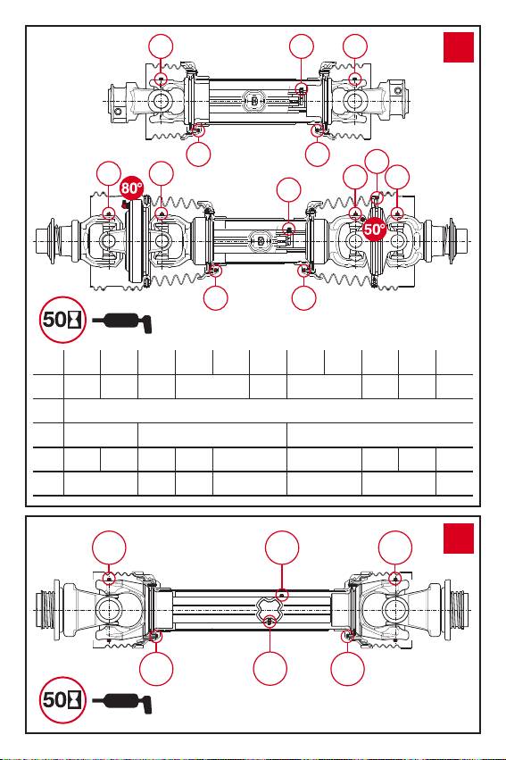
LUBRICATION
Always wear adequate safety equipment when performing any maintenance
33
or repair work.
LUBRICATION OF TELESCOPING TUBES
34
If grease ttings are not provided, separate the two halves of the driveline,
and manually lubricate the telescoping tubes.
GREASING SYSTEM
35
If the driveline is equipped with the Greasing System the telescoping tubes
may be lubricated via the grease tting located next to the tube yoke.
The Greasing System enables rapid lubrication of telescoping tubes at any driveli-
ne position, without removal from either the tractor or implement.
19

ENG
Replace worn or damaged components with genuine Bondioli & Pavesi spa-
36
re parts. Do not modify or tamper with any part of the driveline. For any
operations not explained in this instruction manual, consult your local Bondioli &
Pavesi representative.
Check that all components are in good condition and properly lubricated
37
before using the driveline. Clean and re-lubricate the driveline before sea-
sonal storage.
Lubricate each part after the number of hours shown in chart.
Heavy duty applications in aggressive environments may require more
frequent lubrication intervals.
The quantitiv of grease specied in the manual is recommended for intervals of
50 hours.
Quantities specied in grams (g). 1 ounce (oz.) = 28.3 g (grams).
Inject grease into the cross kit until it purges from each bearing cap.
Pump progressively and avoid high pressures from the grease gun
Recommended grease NLGI 2.
Following seasonal use, it is recommended to clean out any grease inside the CV
shield.
TORQUE LIMITER AND OVERRUNNING CLUTCH
RA - RL OVERRUNNING CLUTCHES
38
This device prevents transmission of inertial loads from implement to the
tractor during deceleration or stopping of the PTO.
Lubricate every 50 hours of use and after storage.
The RL overrunning clutches do not require lubrication and are not equipped
with grease ttings.
Keep clear of the machine until all parts have stopped moving.
SA - LC RATCHET TORQUE LIMITERS
39
This device interrupts the transmission of power when the torque exceeds
the setting.
Immediately disengage the PTO when ratcheting sounds are heard.
Lubricate every 50 hours of use and after storage.
The LC limiters are tted with seal rings and require lubricaion only once each
season.
LN - LT SYMMETRICAL RATCHET TORQUE LIMITERS
40
This device interrupts the transmission of power when the torque exceeds
the setting.
Immediately disengage the PTO when ratcheting sounds are heard.
Lubricate every 50 hours of use and after storage.
The LT limiters are tted with seal rings and require lubricaion only once each
season.
LB – SHEAR BOLT TORQUE LIMITER
41
This device interrupts the transmission of power by shearing a bolt when the
torque exceeds the setting.
Replace the sheared bolt with the same diameter, length and grade as the original.
Lubricate the LB limiters with grease ttings at least once every season and after
long periods of storage.
20

ENG
LR – AUTOMATIC TORQUE LIMITER
42
This device interrupts the transmission of power when the torque exceeds
the setting. To automatically re-engage the device, slow down or stop the PTO.
This device is sealed - no additional lubrication is required.
GE – SHOCK ABSORBING CLUTCH
43
Absorbs shock loads and vibrations, and smoothes transmission of an alter-
nating or pulsating load.
No maintenance is required.
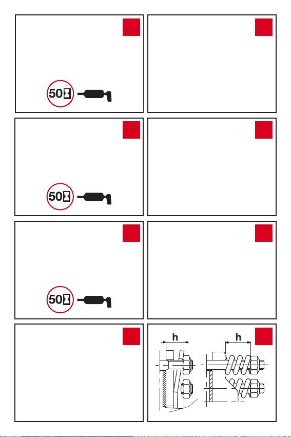
FRICTION TORQUE LIMITERS
Check the condition of the friction linings when installing the clutch or after periods
of storage.
• If the edges of the clutch plates are exposed (see g. 44) the clutch is either type
FV with Belleville spring or FFV with helicoil springs. Measure and record the spring
height as shown in gure 45. If the clutch plates are covered by a metal band (see
gure 46) the clutch is type FT.
If the clutch discs are exposed and the bolts have cap nuts, the clutch is of
the FK type.
Following seasonal use, relieve the spring pressure and keep the clutch in a dry
place. Check the condition of friction disks and restore spring pressure before
using the clutch. If the clutch overheats due to frequent or prolonged slipping,
consult your equipment dealer or manufacturer, or your local Bondioli & Pavesi
representative.
FV - FFV FRICTION TORQUE LIMITER
44
The torque transmitted to the machine is limited by allowing the clutch plates
to slip relative to each other.
Torque peaks or short duration overloads are limited when the clutch is used and
adjusted properly.
It can be used as an overload clutch, or to help start implements with high inertial loads.
The setting can be adjusted by modifying the working height of the springs.
The torque setting of friction torque limiters FV and FFV is adjusted by incre-
45
asing or decreasing the height “h” of the spring.
To increase / reduce the torque setting, screw / unscrew each of the eight nuts
by 1/4 of turn and check for proper operation. Repeat the procedure if necessary.
Avoid excessive tightening of the bolts - implement, tractor, or driveline damage
may occur.
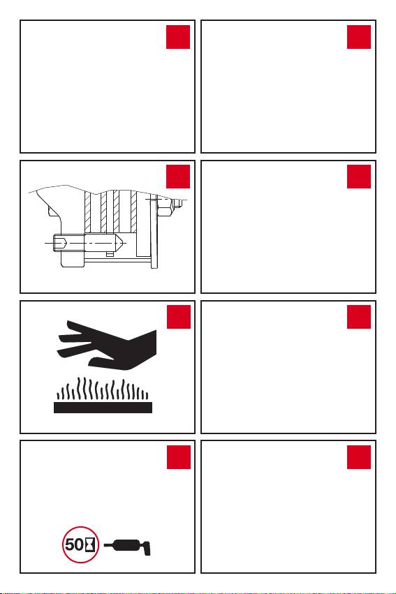
FT - FK FRICTION TORQUE LIMITERS
46
The torque transmitted to the machine is limited by allowing the clutch plates
to slip relative to each other. Torque peaks or short duration overloads are limited
when the clutch is used and adjusted properly. It can be used as an overload
clutch, or to help start implements with high inertial loads. The FT has a metal
band around its circumference. The bolts should be tightened until the metal band
around the circumference of the clutch touches the spring, then loosen each nut
by 1/4 turn. Avoid excessive tightening of the bolts - implement, tractor, or driveline
damage may occur.
The FK clutch has bolts with cap nuts. The spring compression is correct
when the nuts are fully screwed on. Use only special B&P bolts and nuts.
21

ENG
If the clutch has four socket head set screws in addition to the eight hex
47
head bolts on the ange yoke, it is equipped with the Spring Release system.
Spring pressure is relieved when these four set screws are screwed into the ange
yoke. See the instruction leaet enclosed with clutches with the Spring Release
system installed.
The Spring Release System enables checking of the condition of the friction clutch
and reduces spring pressure on the disks during storage.
Friction clutches equipped with the Spring Release System are supplied with
an additional instruction sheet. Read this information for proper use of the
Spring Release System.
Friction clutches may become hot during use. Do not touch!
48
Keep the area around the friction clutch clear of any material which could
cause a re and avoid prolonged slipping of the clutch.
FNV - FFNV - FNT - FNK COMBINATION FRICTION AND OVERRUNNING CLUTCH
49
A clutch which combines the functional characteristics of friction clutch and
an overrunning clutch.
Used on machines with high inertial loads.
Lubricate every 50 hours of use and after storage.
Keep clear of the machine until all parts have stopped moving.
SHIELD DISASSEMBLY
Remove the Philips head screws.
50
Remove the base cone and the shield tube.
51
Remove the outer cone and the bearing ring.
52
SHIELD ASSEMBLY
Grease the bearing groove on inner yokes.
53
Fit the bearing ring into the yoke groove with the grease tting facing the
54
drive tube.
Install the outer cone, inserting the grease tting through the proper hole.
55
Install the base cone and shield tube.
56
Tighten the Philips head screws.
57
Use of electric powered screwdrivers is not recommended.
CV JOINT SHIELD DISASSEMBLY
Remove the screws arranged radially around the circumference of the CV
58
cone.
Remove the screws from the base cone.
59
Remove the base cone and the shield tube.
60
22

ENG
Remove the CV cone.
61
Disengage the retaining spring, leaving it inserted in one of the two holes of
62
the bearing ring to avoid losing it.
Spread the bearing rings and remove from their groove.
63
CV JOINT SHIELD ASSEMBLY
Grease the bearing grooves.
64
Fit the bearing ring into the yoke groove with the grease tting facing the
drive tube.
Install the bearing ring on the CV body with the reference pins facing the
65
inner yoke. The bearing ring is equipped with a grease tting, used only for
50° CV joints. This grease tting is not used with 80° CV joints.
Connect the retaining spring to the two edges of the bearing ring.
66
Slide the CV cone onto the CV body and align the radial holes with the be-
67
aring ring reference pins. Align the hole at the base of the CV cone with the
grease tting on the smaller bearing ring.
In the case of 50° CV joints only: insert the shield strip, aligning with the
68
elements specied in point 66, and also the additional hole of the shield strip
with the grease tting of the large ring.
Ensure that the radial holes of the CV cone are aligned with the holes on the
69
reference pins of the bearing ring.
In the case of 50° CV joints only: Ensure that the radial holes of the shield
70
strip are aligned with the holes on the reference pins of the bearing ring
and that the access hole on the CV cone is aligned with the grease tting of the
bearing ring.
Tighten the 6 flange head screws of the protection strip. The use of an elec-
71
tric screwdriver is not recommended.
Fit the base cone and tube, inserting the grease tting in the hole on the
72
base cone.
Tighten the 3 screws. Use of electric powered screwdrivers is not recommended.
73
SHORTENING THE DRIVELINE
Bondioli & Pavesi does not recommend modications to its products.
74
If the driveline needs to be shortened, proceed as described below.
If you are unsure of the procedure, or need additional assistance, please contact
your local implement dealer or qualied service center.
Remove shielding.
75
23

ENG
Shorten drive tubes by the required length. In normal conditions, telesco-
76
ping tubes must always overlap by at least a 1/2 of their length. During ma-
noeuvres, when the driveline is not rotating, the telescoping tubes must have a
suitable overlap to maintain the tubes aligned and allow then to slide properly. If
the driveline is tted with a single chain restraint system (splined inner tube), the
tubes can be shortened by a limited amount (normally no more than 70 mm) to
avoid eliminating the splined ring connecting the two shield tubes. If the driveline
is tted with a greasing system incorporated in the inner drive tube, the tubes
can be shortened by a limited amount to avoid damage to the lubrication system.
Carefully measure and shorten each drive tube equally.
Carefully deburr the ends of the tubes with a le and remove any chippings
77
from the tubes.
Shorten shield tubes one at time by cutting the same length that was cut
78
from the drive tubes. If the driveline is equipped with Single Chain Restraint
System, shortening the driveline will involve removal of the plastic ring which con-
nects the shield tubes. If it is necessary to remove this collar, ADD A RETAINING
CHAIN TO THE TRACTOR SIDE OF THE DRIVELINE SHIELD.
Grease the internal drive tube.
79
Reassemble the shielding on the driveshaft.
Check the length of the drive shaft at the minimum and maximum positions
80
of the machine.
Telescoping tubes must always overlap by at least a 1/2 of their length.
During manoeuvres, when the driveline is not rotating, the telescoping tubes must
have a suitable overlap to maintain the tubes aligned and allow then to slide properly.
TROUBLESHOOTING
WEAR OF YOKE EARS
81
EXCESSIVE WORKING ANGLE
• Reduce the working angle.
• Disengage PTO when joint angle exceeds 45°.
DEFORMATION OF YOKES
82
EXCESSIVE TORQUE PEAK OR SHOCK LOAD
• Avoid overloading or engaging PTO when under load.
• Check function of torque limiter.
CROSS ARM BROKEN
83
EXCESSIVE TORQUE PEAK OR SHOCK LOAD
• Avoid overloading or engaging PTO when under load.
• Check function of torque limiter.
ACCELERATED WEAR OF CROSS ARMS
84
EXCESSIVE LOAD
• Do not exceed the speed or power limits indicated in the instruction manual.
INSUFFICIENT LUBRICATION
• Follow instructions in point 37.
24

ENG
SEPARATION OF TELESCOPING TUBES
85
EXCESSIVE EXTENSION OF DRIVELINE
• Do not extend driveline to the point that the tubes separate.
• For stationary machinery, position the tractor so the telescoping tubes overlap as
illustrated in point 10.
TWISTING OR BENDING OF TELESCOPING TUBES
86
EXCESSIVE TORQUE PEAK OR SHOCK LOAD
• Avoid overloading or engaging PTO when under load
• Check function of torque limiter.
• Check that driveline does not come into contact with tractor or implement com-
ponents during movement.
ACCELERATED WEAR OF TELESCOPING TUBES
87
INSUFFICIENT LUBRICATION
• Follow instructions from point 33 to point 37.
INSUFFICIENT TUBE OVERLAP
• Follow instructions in point 10.
ACCELERATED WEAR OF SHIELD BEARING
88
INSUFFICIENT LUBRICATION
• Follow instructions in point 37.
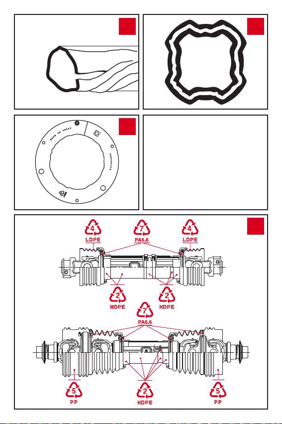
Plastic parts of the Bondioli & Pavesi drivelines are completely recyclable.
89
For a cleaner environment, collect and dispose properly at the time of re-
placement.
25
