Phottix Strato TTL for Canon: инструкция
Раздел: Аксессуары для фото- и видеотехники
Тип:
Инструкция к Phottix Strato TTL for Canon
INSTRUCTION MANUAL
EN
Phottix Strato TTL
for Canon
En
INSTRUCTION MANUAL 2
De
BENUTZERHANDBUCH 22
Fr
MANUEL D’UTILISATION 42
Es
MANUAL DE INSTRUCCIONES 62
It
ISTRUZIONI D’USO 81
Pl
INSTRUKCJA OBSŁUGI 100
Ru
РУКОВОДСТВО ПОЛЬЗОВАТЕЛЯ 119
Simp
Cn
说明书 138
Trad
Cn
說明書 153
1
Parts
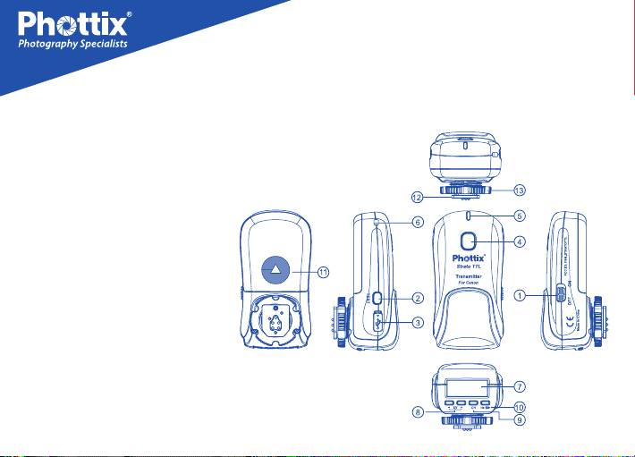
Transmitter
1. Power Switch
2. Test Button
3. USB Port
4. Shutter Button
5. Status LED
6. Lanyard Slot
7. LCD
8. EV -/+ Adjustment Buttons
9. Channel Selection Button
10. HSS / SCS Mode Button /
Key Lock button
11. Battery Compartment
12. Hot Shoe Connector
13. Locking Ring
2
INSTRUCTION MANUAL
EN
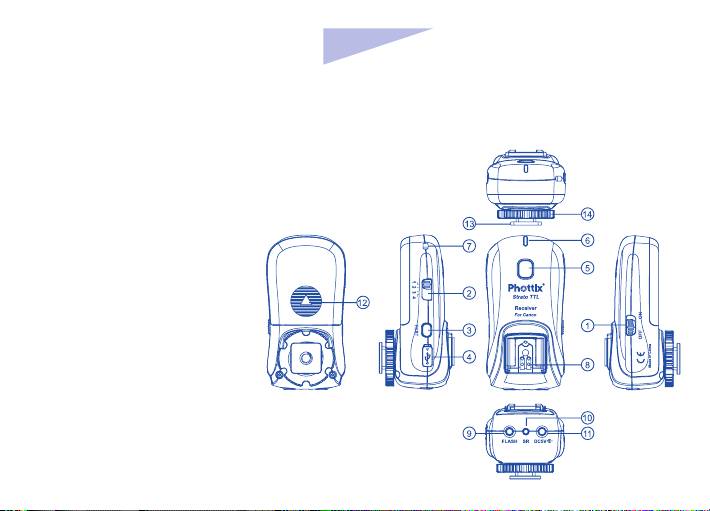
Receiver
1. Power Switch
2. Channel Selection Switch
3. Test Button
4. USB Port
5. Shutter Button
6. Status LED
7. Lanyard Slot
8. Hot Shoe Port
9. Sync Cable Port
10. Shutter Cable Port
11. DC 5V Power Port
12. Battery Compartment
13. Cold Shoe / 1/4 x20 mount
14. Locking Ring
3

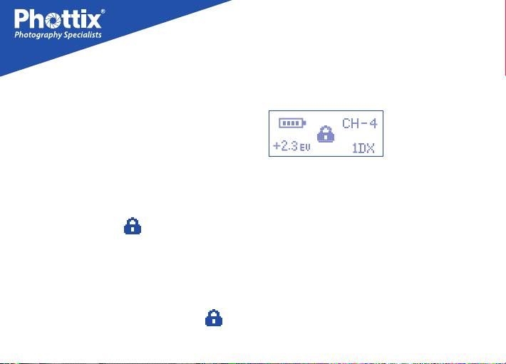
The Transmitter LCD
Compatibility
The Strato TTL Transmitter is compatible with
other Phottix triggers in the following manner:
1. The Strato TTL Transmitter will trigger
Strato and Strato II Receivers and Atlas II
Battery Level Indicator
Transceivers (in RX mode) set to the same
EV Adjustment Level
channel.
Channel
2. The Strato TTL Transmitter will trigger
Strato II receivers set to any group. All Strato
HSS, SCS, Standard Mode
II Receiver groups will fire if set to the same
Key Lock Mode
channel as the Strato TTL transmitter.
3. The Strato TTL Transmitter will not trigger
Phottix Odin or Ares.
Tip: Turn off all devices – flashes/strobes,
cameras, and Phottix Strato TTL transmitters
4. Phottix Odin TCU or Atlas II (in Tx mode) or
and receivers - when connecting and
Ares Transmitter will not trigger Strato TTL
disconnecting devices.
Receivers.
4

INSTRUCTION MANUAL
EN
5. Using the Strato TTL Transmitter in HSS
Battery Level Indicator
mode may cause issues with ash sync when
When the battery voltage is higher than 2.4V,
using Strato and Strato II Multi receivers or
the battery level indicator icon will display
Atlas II Transceivers (in RX mode).
four bars . As power in the batteries is
depleted the bars displayed in the battery
level indicator icon will disappear. When the
Inserting batteries
batteries are exhausted the battery level
1. Press the battery cover in while pushing
indicator will display an empty with battery
it away from the Strato TTL transmitter or
icon .
receiver. The battery cover will snap open and
slide away from the device.
LCD Backlight on the transmitter
2. Remove the battery cover from the Strato
TTL.
Pressing any button on the transmitter
will illuminate the LCD Backlight for
3. Insert AA batteries.
approximately 10 seconds. If no buttons on
4. Replace the battery cover and push back
the transmitter are pressed, the backlight will
into the locked position.
go o.
5
Auto-idle function
1Dx mode
The transmitter will enter Auto Idle Mode with
“IDLE” displaying on the LCD after 10 minutes
of inactivity.
The Strato TTL Trigger comes with a 1Dx
Key Lock Mode
mode for better compatibility with this model
1. Pressing and holding the HSS / SCS Mode
of camera.
Button / Key Lock button for 2 seconds will
To Enable/Disable1Dx mode:
display a lock icon . Transmitter Buttons
1. Press and hold the “EV+” and "HI/SCS"
will be locked, pressing buttons will not make
buttons to enable 1Dx mode.
changes.
2. Press and hold the “EV+” and "HI/SCS"
2. While in Key Lock Mode, pressing and
buttons again to disable 1Dx mode.
holding the HSS / SCS Mode Button / Key
Lock button for 2 seconds will unlock
Please note:
the transmitter and the lock icon will
-When the 1Dx mode is enabled, the flash
disappear.
6

INSTRUCTION MANUAL
EN
sync mode will not support Second Curtain
2. To Test: Press the transmitter Test Button.
Sync (SCS) functions.
Flashes connected to Phottix Strato TTL
receivers on the same channel will re when
-If not using a 1Dx camera ensure this mode
the transmitter test button is pressed.
is disabled for best results.
3. Pressing the receiver Test Button will test
fire flashes or strobes connected to that
Turning transmitter and receiver on/
receiver.
o
For Wireless Shutter Release: See Using the
Strato TTL as a wireless shutter release below
1. To turn on the Phottix Strato TTL
transmitter or receiver– move the power
switch to the “ON” position.
Status LED
2. To turn off the Phottix Strato TTL
1. The Status LED on the Strato TTL transmitter
transmitter or receiver - move the power
will flash green once every 2 seconds while
switch to the “OFF” position.
the power is on and turn solid green upon a
Test Button
half-press of the shutter button (on camera
or the Strato TTL transmitter being used as
1. The Test Button will test re ashes/strobes.
7

a wireless shutter release). The LED will turn
2. Channels can be set on both the
red when sending a signal or taking a photo.
transmitter and receiver.
When idle, the Status LED will go out.
2. The Status LED on the Strato TTL receiver
Setting Channels on the Transmitter
will flash green once every 2 seconds while
the power is on and in standby. The LED
1. Press the Channel Selection Button on the
will turn red when a signal is received from
transmitter.
the transmitter and the connected flash or
2. Each press of the button will cycle through
camera is red.
channels 1, 2, 3, 4.
3. When the battery level is low,the Status
3. Make sure the transmitter channel is the
LED on the receiver will ash red once every 2
same as the receivers.
seconds.
4. Channels are visible on the transmitter LCD.
Setting Channels on the Receiver
Channels
1. Move the Channel Selection Switch to
1. The Strato TTL System has 4 transmission
settings 1, 2, 3, or 4.
channels: 1, 2, 3, 4.
8

INSTRUCTION MANUAL
EN
2. Make sure the receiver is set to the same
Connecting a ash to the Strato TTL
channel as the transmitter.
receiver hot shoe
1. Turn off the flash and the Strato TTL
Connecting Strato TTL transmitter to
Receiver.
the camera hot shoe
2. Slide the ash into the receiver’s hot shoe
mount.
1. Turn off the camera and Strato TTL
transmitter.
3. Lock the flash with the flash’s locking
mechanism.
2. Slide the Strato TTL transmitter into the
camera’s hot shoe mount.
4. Turn on the flash and the Strato TTL
receiver.
3. Turn the Strato TTL locking ring until tight.
5. Set the ash to ETTL mode.
4. Turn on the Strato TTL transmitter.
Please Note:
5. Turn on the camera and set the shooting
mode.
It is not unusual for the flash to discharge
once after turning on the Strato TTL.
9

transmitter – flashes connected to receivers
Using the Strato TTL to trigger
on the same channel will not re.
ashes
-Pressing the Test Button on the Strato TTL
1. Half-press the camera shutter button while
transmitter – flashes connected to receivers
the Strato TTL transmitter is connected to
on the same channel will re.
the camera hot shoe and powered on. The
AF assist light of ashes connected to Strato
TTL receivers on the same channel as the
Adjusting EV Levels
transmitter will illuminate. The Status LEDs on
the transmitter and receiver will turn green.
The Strato TTL Flash Trigger System will fire
remote flashes by wireless radio signal. EV
2. A full-press of the camera shutter button
Adjustments can be made to remote ashes
will fire flashes connected to Strato TTL
using the EV -/+ Adjustment Buttons on the
receivers on the same channel as the
transmitter.
transmitter. Status LEDs on the Transmitter
and Receiver will turn red.
To adjust EV levels
Please Note:
1. Press the EV -/+ Adjustment Buttons on
-Pressing the Shutter Button on the Strato TTL
the Strato TTL Transmitter. Changes will be
10

INSTRUCTION MANUAL
EN
displayed on the transmitter.
between HSS, SCS and standard mode.
2. Shoot and make additional changes as
2. Set the camera mode and shutter speed.
needed.
Please Note:
At high shutter speeds the power of ashes is
Using High Speed Sync (HSS) and
greatly reduced.
Second Curtain Sync (SCS)
Pressing the HSS/SCS button will cycle
Supported Camera and Flash
between HSS, SCS and standard operations.
Settings
HSS will allow faster shutter speeds to be
used when firing the flash. Shutter speeds
The Phottix Strato TTL Trigger supports
up to 1/8000 sec. can be achieved with
functions that can be set in camera menus.
compatible cameras and ashes. SCS will re
See your camera and flash manuals for full
the ash at the end of an exposure not at the
details. Functions not available on a camera
beginning. This can be combined with longer
body or ash cannot be used with the Strato
exposures for creative eects.
TTL system.
1. Press the HSS / SCS Mode Button to cycle
1. Depth-of Field Preview Button (Modeling
11

Flash): Pressing the Depth of Field Preview
can be manually tested and locked by
Button on the camera will causes flashes
pressing the AE-L/AF-L button on the camera.
connected to receivers on the same channel
5. Exposure Compensation: The Strato TTL
(with the function enabled) to flash. This is
system supports exposure compensation
useful for previewing lighting set-ups.
setting for the ash from the camera menu /
2. Autofocus Assist Light: The AF Assist Light
controls.
of the ash connected a Strato TTL Receiver
6. Zoom: Flash head zoom can be controlled
on the same channel as a transmitter will
in two ways (when a flash is set to "Auto"
illuminate when needed to assist with focus (if
zoom mode, not manual zoom. See your ash
the function is enabled).
manual for further details) If the focal length
3. Sync Mode: The Strato TTL supports Sync
of a camera zoom lens is changed, the zoom
Mode settings for the flash through camera
of a ash connected to a Strato TTL Receiver
menu “Shutter Sync.” First Curtain Sync,
on the same channel as a transmitter will
Second Curtain Sync and High Speed Sync
change dynamically. When flash zoom is
can be enabled on the camera through this
changed from a camera menu the zoom of a
menu.
flash connected to a Strato TTL Receiver on
the same channel as a transmitter will also
4. Exposure Lock (FEL): The flash exposure
change correspondingly.
12

INSTRUCTION MANUAL
EN
7. Metering Mode: Setting Average or
Connecting the Strato TTL receiver
Evaluative metering mode for the flash
to flashes or studio lights by sync
through camera menu is supported.
cable
8. Changing Channels: After enabling
1. Turn off the flash/studio light and the
wireless ash functions on the camera, ash
Strato TTL receiver.
transmission channels can be changed in the
camera menu. Changes made to channels in
2. Connect a cable to the receiver’s 3.5 mm
the camera menu will change the working
Sync Port.
channel of the Strato TTL Transmitter on the
3. Connect the opposite end of the cable to
camera.
a ash or studio strobe (A 6.3 mm adapter is
Please note:
included for studio strobes with larger ports).
- If the “wireless ash functions” in the camera
4. Turn on the flash/strobe and the Phottix
set-up menus has been enabled Second
Strato TTL receiver. Set the flash/strobe to
Curtain Sync Functions will not work. The
Manual mode (if applicable).
“Wireless flash functions” selection needs
5. Press the Shutter Button of the camera
to be disabled to use Second Curtain Sync
connected to the transmitter -- flashes
functions.
13

connected to the receivers on the same
mm Accessory Port on the Strato TTL receiver
channel will re.
3. Attach the other end of the cable to the
Please note:
camera’s remote port.
- It is not unusual for the flash to discharge
4. Turn on the camera and Phottix Strato TTL
once after turning on the Phottix Strato TTL.
receiver. Consult your camera manual for
specic settings for remote use.
- Flashes connect to Strato TTL receivers by
cable will have no TTL, HSS or SCS functions,
5. Using the Phottix Strato TTL transmitter
only simple triggering
will allow for remote wireless shutter release
functions. The Strato TTL shutter button
functions the same as a camera shutter
Using the Strato TTL as a wireless
button: A half-press of the shutter button will
autofocus, a full press will take a photo.
shutter release*
Please Note:
1. Turn o the camera and the Phottix Strato
TTL receiver.
When using the transmitter as a wireless
shutter release, pressing the shutter button
2. Attach the correct Phottix Accessory Cable
on the transmitter will only trigger cameras
for your camera make and model to the 2.5
14

INSTRUCTION MANUAL
EN
connected to receivers on the same channel.
receiver**.
It will not fire the flashes connected to the
5. Consult your camera manual for specific
receivers on the same channel.
settings for remote use.
*On compatible cameras
6. The Strato TTL receiver will function as a
wired shutter release. The shutter button
functions the same as a camera shutter
Using the Strato TTL as a wired
button: A half-press of the shutter button will
shutter release*
autofocus, a full press will take a photo.
1. Turn off the camera and the Strato TTL
*On compatible cameras
receiver.
**Wired Shutter Release function can be used
2. Attach the correct Phottix Accessory Cable
without turning on the Strato TTL receiver,
for your camera make and model to the 2.5
and will function without batteries in the
mm Accessory Port on the Strato TTL receiver
receiver.
3. Attach the other end of the cable to the
camera’s remote port.
4. Turn on the camera and Strato TTL
15

Warnings
- This product is a precise electronic
instrument. Do not expose to damp
environments or dust.
- Do not drop or crush.
- Do not use harsh chemical(s) or solvents to
clean the body. Use a soft cloth or lens paper.
- Interference: The Phottix Strato TTL
transmits and receives radio signals at 2.4
GHz. Its performance can be affected by
electrical current, magnetic fields, radio
signals, wireless routers, cellular phones,
and other electronic devices. Environmental
objects, such as large buildings or walls, trees,
fences, or cars can also aect performance. If
your Strato TTL receiver will not trigger move
its location slightly.
16

INSTRUCTION MANUAL
EN
Technical Specications
:
Transmitting power :
≤10dBm
Attachment: 1/4” tripod lug, cold shoe
(Receiver)
Distance
:
100m+
Weight: Transmitter 74g; Receiver 72g----
Frequency: 2.4GHz
without batteries
Channel: 4 channels
Body dimension:
Transmitter L 92.5 * W 47.8 *
Input voltage
:
2.2V-3.2V
H 45.5 mm; Receiver L 93.3 * W 46.7 * H 45.4 mm
Flash port voltage handling: Transmitter 6V;
Antenna
:
Built-in PCB antenna
Receiver ≤300V
Operating temperature: 0
℃~
+50
℃
Batteries: 2xAA alkaline batteries or
rechargeable batteries (Transmitter and
Operating humidity: 35%
~
95%RH
Receiver); 5V DC on Receiver (external power
port)
Max sync speed: 1/8000s
Output: hot shoe, 3.5mm (Receiver)
Input: USB port (transmitter and Receiver)
17

Product: Phottix Strato TTL Flash Trigger
EC Declaration of Conformity
Transmitter; Phottix Strato TTL Flash
We Phottix (HK) Ltd.
Trigger Receiver
Of 10/F Block A, Yip Fat Factory Building,
Model Number: Strato TTL Transmitter;
Phase 1, 77 Hoi Yuen Rd, Kwun Tong, Kln,
Strato TTL Receiver
Hongkong
complies with the relevant fundamental
The European Authorized Representative
requirements as per R&TTE Directive 1999/5/
EC,insofar as the product is used correctly,
Phottix Europe Sp. z o.o.
and the following standards or other
Piotrkowska 66
normative documents
90-105 Lodz, Poland
EN 62479:2010-09
KRS 0000327336
ETSI EN 300 440-1 V1.6.1(2010-08)
ETSI EN 300 440-2 V1.4.1(2010-08)
declare herewith that the product designated
ETSI EN 301 489-1 V1.9.2/2011-09
below:
ETSI EN 301 489-3 V1.4.1/2002-08
18
INSTRUCTION MANUAL
EN
Signed by:
Paul Czernik
CEO/Prezes Zarządu
Phottix Europe Sp. z o.o.
Lodz, October 2013
19

approved by the party responsible for
FCC Compliance Information
compliance could void the user’s authority to
For Transmitter
operate the equipment.
Company: Phottix (HK) Ltd.
NOTE: This equipment has been tested and
Name: Phottix Strato TTL Flash Trigger
found to comply with the limits for a Class B
Transmitter
digital device, pursuant to Part 15 of the FCC
Model Number: Strato TTL Transmitter
Rules. These limits are designed to provide
FCC ID: P9M-STRATOTTL
reasonable protection against harmful
interference in a residential installation.
This device complies with Part 15 of the FCC
This equipment generates, uses and can
Rules. Operation is subject to the following
radiate radio frequency energy and, if not
two conditions: (1) this device may not cause
installed and used in accordance with the
harmful interference, and (2) this device must
instructions, may cause harmful interference
accept any interference received, including
to radio communications.
interference that may cause undesired
However, there is no guarantee that
operation.
interference will not occur in a particular
Changes or modifications not expressly
installation. If this equipment does cause
20

INSTRUCTION MANUAL
EN
harmful interference to radio or television
For Receiver
reception, which can be determined by
This device complies with Part 15 of the FCC
turning the equipment o and on, the user is
Rules. Operation is subject to the following
encouraged to try to correct the interference
two conditions: (1) this device may not cause
by one or more of the following measures:
harmful interference, and (2) this device must
--Reorient or relocate the receiving antenna.
accept any interference received, including
interference that may cause undesired
--Increase the separation between the
operation.
equipment and receiver.
--Connect the equipment into an outlet on
a circuit different from that to which the
receiver is connected.
--Consult the dealer or an experienced radio/
TV technician for help.
21
