Planet POE-152S: 5. Hardware Installation
5. Hardware Installation: Planet POE-152S
5. Hardware Installation
English
This section describes the hardware features of PoE Splitter. Before
connecting any network device to the PoE Splitter, refer to this
chapter carefully.
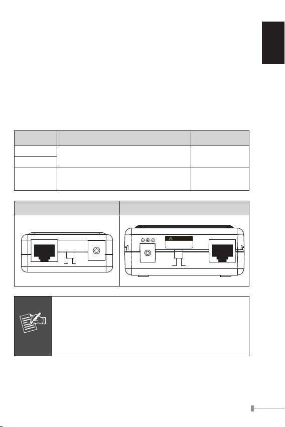
5.1 Before Installation
The PLANET PoE Splitter separates the power out and provides two
kind of DC power output through its DIP switch and its voltage and
current shown as below:
Model DIP switch for DC Voltage Output Default Mode
POE-151S
5V DC / 2A
5V DC
POE-152S
12V DC / 1A
12V DC / 2A
POE-162S
12V DC
24V DC / 1A
POE-151S / POE-152S POE-162S
1-3
Ethernet+DC
Power in-use
Ready
PoE
PoE-IEEE 802.3af
IEEE 802.3af
Power over Ethernet Splitter
Ethernet
5V 12V
DC OUT
PoE In
before change 12/24V
Disconnect "PoE In" cable
Note
IEEE 802.3at High Power PoE Splitter
PoE In
CAUTION
Incorrect voltage might
cause device damage
DC Out Ethernet
24V 12V
Note
The PLANET PoE Splitter and PLANET PoE Injector (ex.
POE-151, POE-152 and POE-161) can be installed in
pair. Use of third-party PoE Injector device is allowed if
the device complied with IEEE 802.3at or IEEE 802.3af
standard.
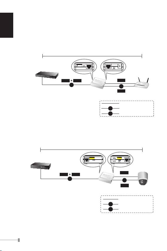
5.2 802.3af/at Device Installation
The PLANET PoE Splitter also provide the alternative to make the non
IEEE 802.3af / 802.3at devices the possibility to connect with an IEEE
English
802.3af / 802.3at PSE power device like Power over Ethernet Injector
or Power over Ethernet Switch, the gure is as below.
1-4
100 meters
PoE-IEEE 802.3af
PoE
Ready
Power in-use
802.3af in-line power Switch
Ethernet+DC
Ethernet
5V 12V
DC OUT
Data
Power
Data
PoE
DC
Power
Wireless AP
POE-151S
POE-152S
100Base-TX UTP
DC
Power Line (DC)
PoE
100Base-TX UTP with PoE
Figure 3: Connection to IEEE 802.3af Device
100 meters
802.3at in-line power Switch
PoE In
DC Out Ethernet
24V 12V
Data
Data
Power
PoE
DC
Power
POE-162S
PTZ Speed
Dome
1000Base-T UTP
PoE
1000Base-T UTP with PoE
DC
Power Line (DC)
Figure 4: Connection to IEEE 802.3at Device

English
1-5
Note
With IEEE 802.3af / 802.3at standard; the PLANET PoE
Splitter also can co-work with IEEE 802.3af / 802.3at
End-Span Switch that feeding power over pin 1, 2, and
3, 6.
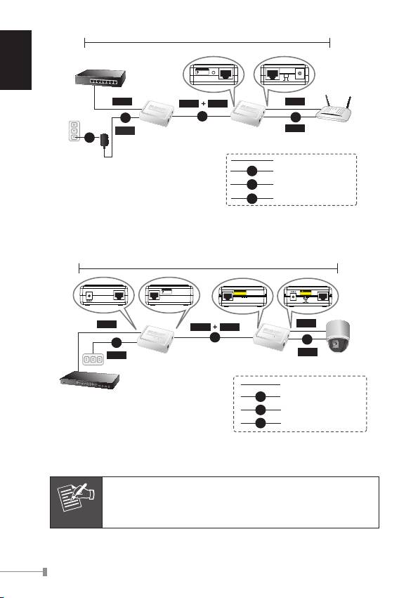
5.3 PoE Injector and PoE Splitter Installation
For non PoE remote device or Ethernet equipment, the PoE Splitter
and PoE Injector can runs in pair to provide DC Power for those
devices, the table below shows the model of PLANET PoE Injectors:
Model PoE Standard Max. PoE Out Power In Pass-thru. Speed
POE-151 IEEE 802.3af 15.4 Watts 48V DC 10/100Mbps
POE-152 IEEE 802.3af 15.4 Watts 48V DC 10/100/1000Mbps
POE-161 IEEE 802.3at / af 30 Watts 56V DC 10/100/1000Mbps
Steps:
1. [Switch & PoE Injector] Connect a standard network UTP cable
from Switch / workstation to “Ethernet” port of PoE Injector and
the PoE Injector get DC power from attached power adapter.
2. [PoE Injector & PoE Splitter]
Connect the long UTP cable between the port “Ethernet+DC” of
PoE Injector to the port “Ethernet+DC” (or “PoE IN”) of PoE
Splitter.
The PoE LEDs of both Injector and Splitter will light on continu-
ance.
3. [PoE Splitter]
Connect the UTP cable in the package from “Ethernet” of the
PoE splitter to the RJ-45 port of remote device.
Adjust proper DC power output and connect proper DC plug from
“DC OUT” of PoE Splitter to the remote device.
English
1-6
100 meters
Ethernet Switch
PoE-IEEE 802.3af
PoE
Ready
Power in-use
Ethernet+DC
Ethernet
5V 12V
DC OUT
Data
Data
Data
Power
DC
PoE
DC
Power
Wireless AP
Power
POE-151/152
POE-151S
AC
PoE Injector
PoE Splitter
100Base-TX UTP
DC
Power Line (DC)
AC
Power Line (AC)
PoE
100Base-TX UTP with PoE
Figure 5: Connection Architecture via 802.3af PoE Injector and PoE Splitter
100 meters
56V DC
Ethernet
Ethernet+DC
PoE In
DC Out Ethernet
24V 12V
Data
Data
Data
Power
PoE
DC
AC
Power
Power
POE-162S
POE-161
PTZ Camera
1000Base-T UTP
Switch
PoE
1000Base-T UTP with PoE
AC
Power Line (AC)
DC
Power Line (DC)
Figure 6: Connection Architecture via 802.3at PoE Injector and PoE Splitter
Note
Please ensure the PoE Splitter output voltage is correct
before applying power to remote device otherwise, it
may damage the remote device.
Оглавление
- Table of Contents
- 1. Overview
- 3. Product Outlook
- 5. Hardware Installation
- 6. Product Specication
- 1. Vue d’ensemble
- 3. Détail du produit
- 5. Installation du matériel
- 6. Caractéristiques du produit
- 1. Überblick
- 3. Produkt Ansicht
- 5. Hardware Installation
- 6. Produkt Spezikation
- 1. Informazioni generali
- 3. Vista del Prodotto
- 5. Hardware Installation
- 6. Speciche del Prodotto
- 1. Apresentação
- 3. Apresentação do Produto
- 5. Instalação do Equipamento
- 6. Especicação do Produto
- 1. Обзор
- 3. Внешний вид продукта
- 4. Светодиодная индикация
- 6. Характеристики продукта
- 1. Información general
- 3. Vista general del Producto
- 5. Instalación del hardware
- 6. Especicación de Producto
