De Dietrich MS 24 MI – страница 4
Инструкция к Настенному Котлу De Dietrich MS 24 MI
24 FF
CG_2267 / 1006_2102
Mandata
Mandata
Gas Entrata
Ritorno
riscaldamento
bollitore
sanitario
riscaldamento
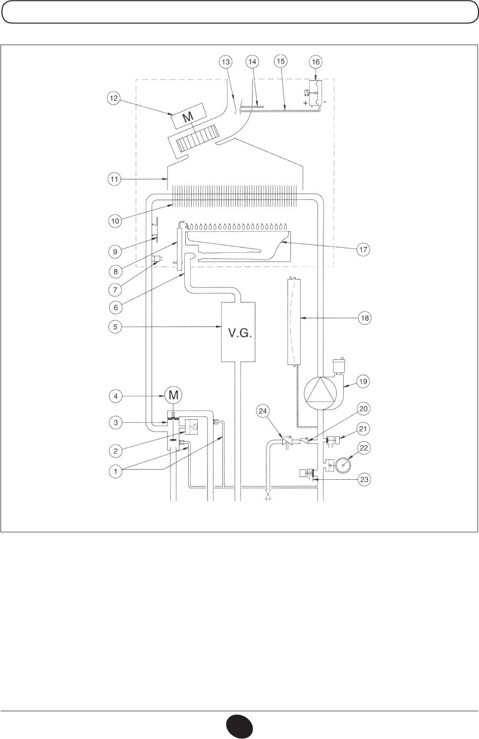
Figura 19
Legenda:
1 By-pass automatico con valvola di ritegno
13 Venturi
2 Pressostato idraulico
14 Presa di pressione positiva
3 Valvola tre vie
15 Presa di pressione negativa
4 Motore valvola tre vie
16 Pressostato aria
5 Valvola gas con diaframma gas
17 Bruciatore
6 Rampa gas con ugelli
18 Vaso espansione
7 Sonda NTC riscaldamento
19 Pompa con separatore d’aria
8 Elettrodo di accensione / rivelazione amma
20 Valvola di non ritorno
9 Termostato di sicurezza
21 Rubinetto di scarico caldaia
10 Scambiatore acqua fumi
22 Manometro
11 Convogliatore fumi
23 Valvola di sicurezza
12 Ventilatore
24 Disconnettore
ISTRUZIONI DESTINATE ALL’INSTALLATORE
71.03982.03 - IT
61
24
CG_2268 / 1006_2103
Mandata
Mandata
Gas Entrata
Ritorno
riscaldamento
bollitore
sanitario
riscaldamento
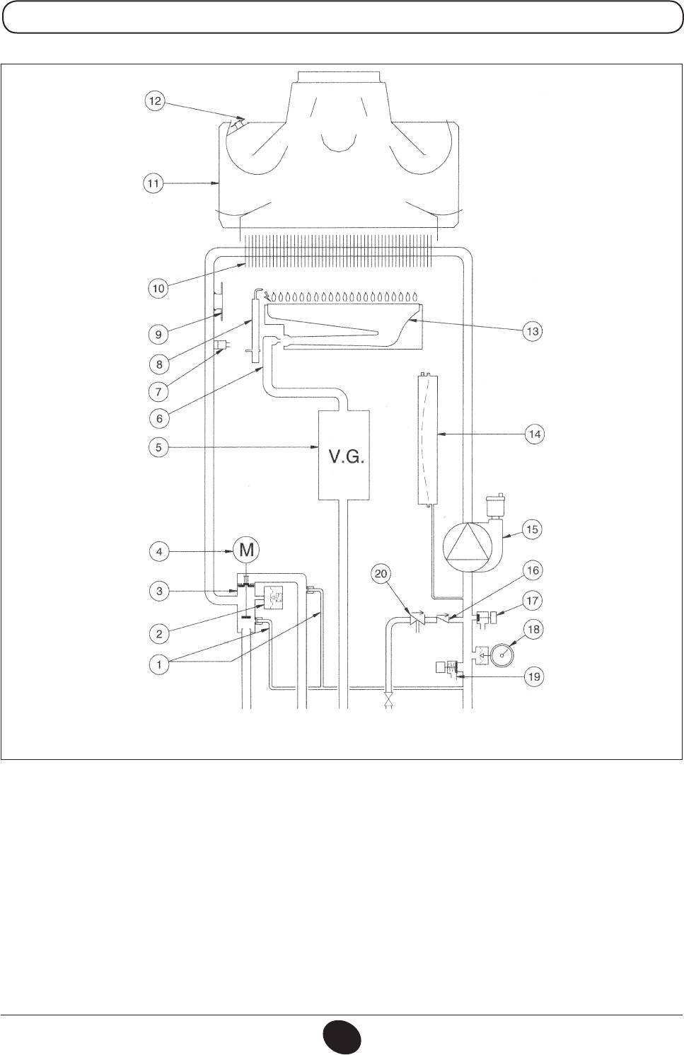
Figura 20
Legenda:
1 By-pass automatico con valvola di ritegno
11 Convogliatore fumi
2 Pressostato idraulico
12 Termostato fumi
3 Valvola tre vie
13 Bruciatore
4 Motore valvola tre vie
14 Vaso espansione
5 Valvola gas con diaframma gas
15 Pompa con separatore d’aria
6 Rampa gas con ugelli
16 Valvola di non ritorno
7 Sonda NTC riscaldamento
17 Rubinetto di scarico caldaia
8 Elettrodo di accensione / rivelazione amma
18 Manometro
9 Termostato di sicurezza
19 Valvola di sicurezza
10 Scambiatore acqua fumi
20 Disconnettore
ISTRUZIONI DESTINATE ALL’INSTALLATORE
71.03982.03 - IT
62
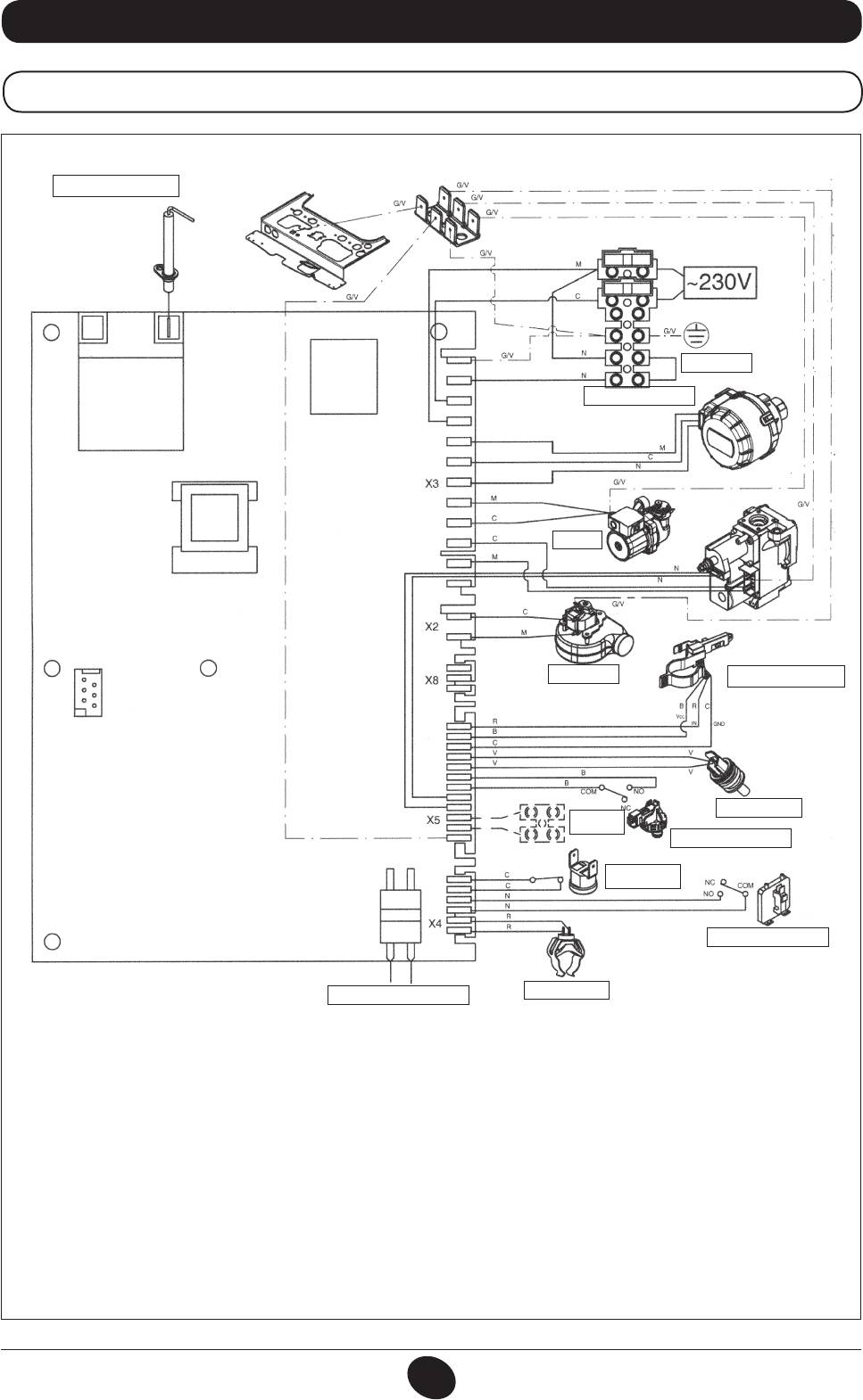
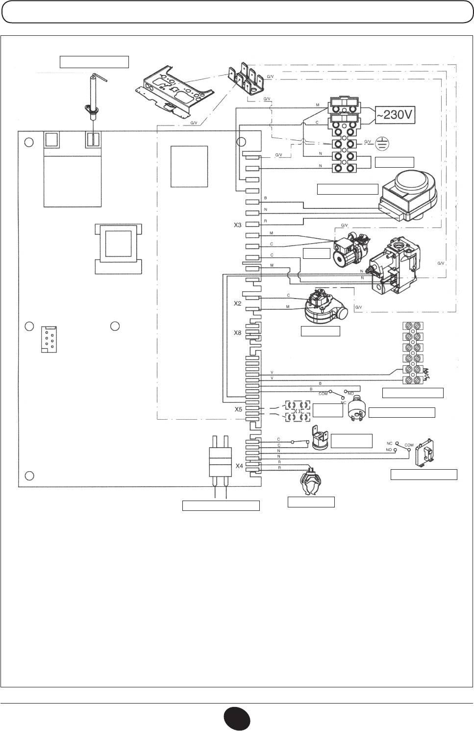
34. SCHEMA COLLEGAMENTO CONNETTORI
24 MI FF
ELETTRODO DI
RIVELAZIONE/ACCENSIONE
CG_2075 / 1001_1806
TERMOSTATO
VALVOLA TRE VIE
POMPA
VENTILATORE
SENSORE PRECEDENZA
SANITARIO
SONDA NTC SAN.
SONDA
ESTERNA
PRESSOSTATO IDRAULICO
TERMOSTATO DI
SICUREZZA
PRESSOSTATO ARIA
SONDA NTC RISC.
PROGRAMMAZIONE
Colore cavetti
C = Celeste
M = Marrone
N = Nero
R = Rosso
G/V = Giallo/Verde
B = Bianco
V = Verde
ISTRUZIONI DESTINATE ALL’INSTALLATORE
71.03982.03 - IT
63
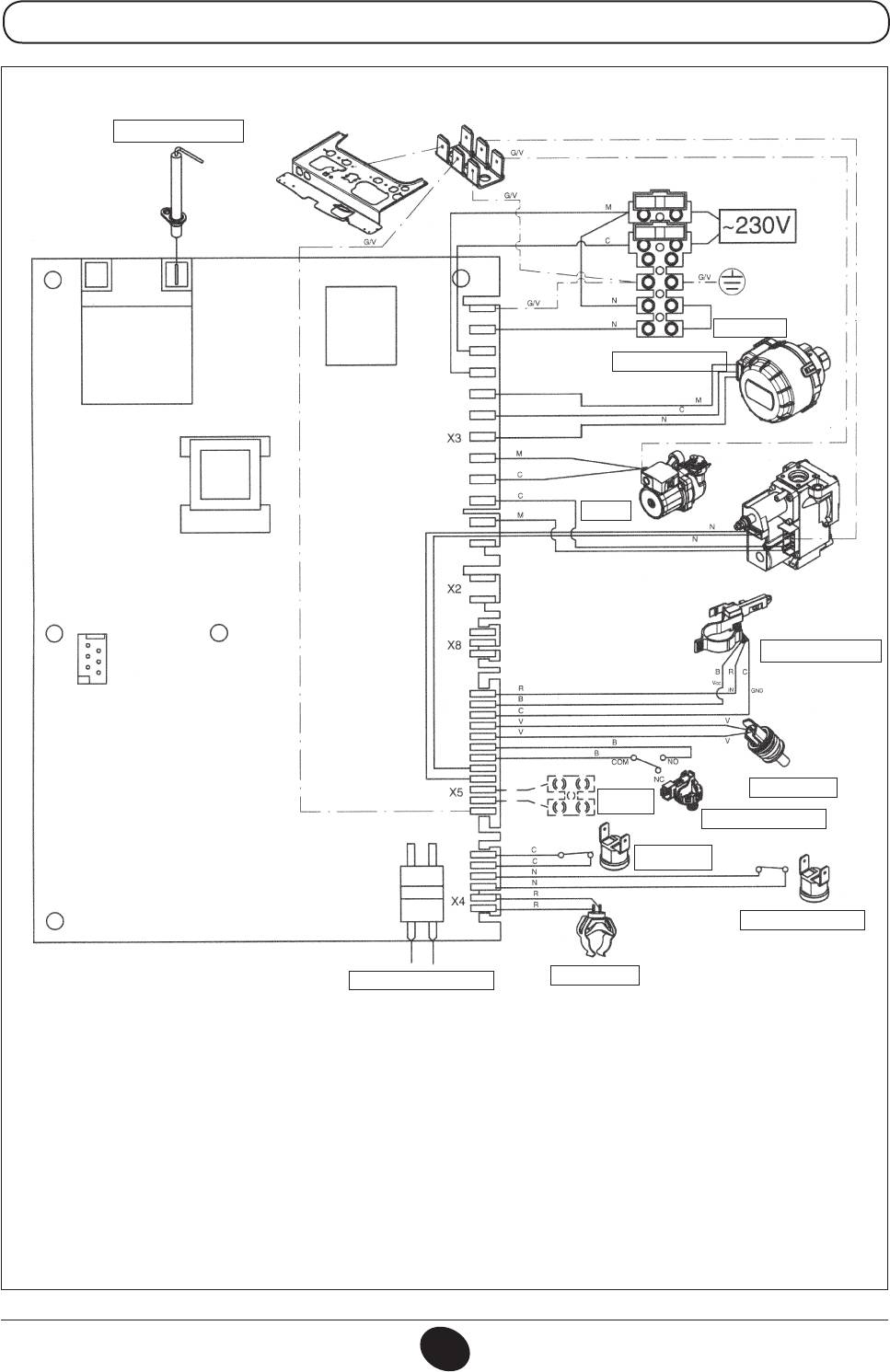
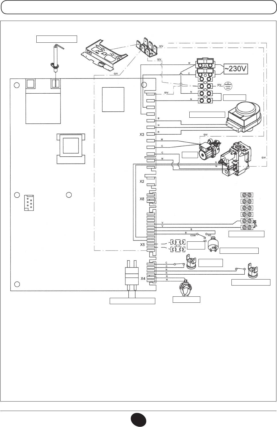
24 MI
ELETTRODO DI
RIVELAZIONE/ACCENSIONE
CG_2076 / 1001_1807
TERMOSTATO
VALVOLA TRE VIE
POMPA
SENSORE PRECEDENZA
SANITARIO
SONDA NTC SAN.
SONDA
ESTERNA
PRESSOSTATO IDRAULICO
TERMOSTATO DI
SICUREZZA
TERMOSTATO FUMI
SONDA NTC RISC.
PROGRAMMAZIONE
Colore cavetti
C = Celeste
M = Marrone
N = Nero
R = Rosso
G/V = Giallo/Verde
B = Bianco
V = Verde
ISTRUZIONI DESTINATE ALL’INSTALLATORE
71.03982.03 - IT
64
24 FF
ELETTRODO DI
RIVELAZIONE/ACCENSIONE
CG_2271 / 1006_1603
TERMOSTATO
VALVOLA TRE VIE
POMPA
VENTILATORE
MORSETTIERA M2
SONDA
ESTERNA
PRESSOSTATO IDRAULICO
TERMOSTATO DI
SICUREZZA
PRESSOSTATO ARIA
SONDA NTC RISC.
PROGRAMMAZIONE
Colore cavetti
C = Celeste
M = Marrone
N = Nero
R = Rosso
G/V = Giallo/Verde
B = Bianco
V = Verde
ISTRUZIONI DESTINATE ALL’INSTALLATORE
71.03982.03 - IT
65
24
ELETTRODO DI
RIVELAZIONE/ACCENSIONE
CG_2272 / 1010_2101
TERMOSTATO
VALVOLA TRE VIE
POMPA
MORSETTIERA M2
SONDA
ESTERNA
PRESSOSTATO IDRAULICO
TERMOSTATO DI
SICUREZZA
TERMOSTATO FUMI
SONDA NTC RISC.
PROGRAMMAZIONE
Colore cavetti
C = Celeste
M = Marrone
N = Nero
R = Rosso
G/V = Giallo/Verde
B = Bianco
V = Verde
ISTRUZIONI DESTINATE ALL’INSTALLATORE
71.03982.03 - IT
66
35. CARATTERISTICHE TECNICHE
Modello MS 24 MI FF 24 FF 24 MI 24
Categoria II2H3P
II2H3P
II2H3P II2H3P
Portata termica nominale kW 25,8 25,8 26,3 26,3
Portata termica ridotta kW 10,6 10,6 10,6 10,6
Potenza termica nominale kW 24 24 24 24
kcal/h 20.600 20.600 20.600 20.600
Potenza termica ridotta kW 9,3 9,3 9,3 9,3
kcal/h 8.000 8.000 8.000 8.000
Rendimento secondo la direttiva 92/42/CEE — ★★★ ★★★ ★★ ★★
Pressione massima acqua circuito termico bar 3 3 3 3
Capacità vaso espansione l 6 6 6 6
Pressione del vaso d’espansione bar 1 1 1 1
Pressione massima acqua circuito sanitario bar 8 — 8 —
Pressione minima dinamica acqua circuito sanitario bar 0,15 — 0,15 —
Portata minima acqua sanitaria l/min 2,0 — 2,0 —
Produzione acqua sanitaria con ∆T=25 °C l/min 13,7 — 13,7 —
Produzione acqua sanitaria con ∆T=35 °C l/min 9,8 — 9,8 —
Portata specica (*) l/min 12 — 12 —
Range temperatura circuito di riscaldamento °C 30/85 30/85 30/85 30/85
Range temperatura acqua sanitaria °C 35/60 35/60*** 35/60 35/60***
Tipo — C12-C32-C42-C52-C82-B22
B
B
11BS
11BS
Diametro condotto di scarico concentrico mm 60 60 - -
Diametro condotto di aspirazione concentrico mm 100 100 - -
Diametro condotto di scarico sdoppiato mm 80 80 - -
Diametro condotto di aspirazione sdoppiato mm 80 80 - -
Diametro condotto di scarico mm - - 125 125
Portata massica fumi max kg/s 0,014 0,014 0,020 0,020
Portata massica fumi min. kg/s 0,014 0,014 0,018 0,018
Temperatura fumi max °C 146 146 110 110
Temperatura fumi min. °C 116 116 85 85
Classe NOx — 3 3 3 3
Tipo di gas — G20 G20 G20 G20
— G31 G31 G31 G31
Pressione di alimentazione gas metano mbar 20 20 20 20
Pressione di alimentazione gas propano mbar 37 37 37 37
Tensione di alimentazione elettrica V 230 230 230 230
Frequenza di alimentazione elettrica Hz 50 50 50 50
Potenza elettrica nominale W 130 130 80 80
Peso netto kg 33 32 29 28
Dimensioni altezza mm 730 730 730 730
larghezza mm 400 400 400 400
profondità mm 299 299 299 299
Grado di protezione contro l’umidità e la penetrazione dell’acqua (**) IP X5D IP X5D IP X5D IP X5D
(*) secondo EN 625
(**) secondo EN 60529
(***) con bollitore esterno
DE DIETRICH, nella costante azione di miglioramento dei prodotti, si riserva la possibilità di modicare i dati espressi in questa documentazione
in qualsiasi momento e senza preavviso. La presente documentazione è un supporto informativo e non considerabile come contratto nei
confronti di terzi.
ISTRUZIONI DESTINATE ALL’INSTALLATORE
71.03982.03 - IT
67
Dear Customer,
We are condent your new boiler will meet all your requirements.
All De Dietrich products have been designed to give you what you are looking for: good performance
combined with simple and rational use.
Please do not put away this booklet without reading it rst as it contains some useful information
which will help you to operate your boiler correctly and efciently.
Do not leave any packaging (plastic bags, polystyrene, etc.) within the reach of children as they are a potential
source of danger.
De Dietrich declares that these models of boiler bear the CE mark in compliance
with the basic requirements of the following Directives:
- Gas directive 2009/142/EC
- Efciency Directive 92/42/EEC
- Electromagnetic Compatibility Directive 2004/108/EC
- Low Voltage Directive 2006/95/EC
CONTENTS
INSTRUCTIONS FOR USERS
1. Instructions prior to installation 69
2. Instructions prior to commissioning 69
3. Commissioning the boiler 70
4. Adjusting room and DHW temperatures 71
5. Description of button ( ) (Summer - Winter - Heating only - Off) 71
6. Filling the system 72
7. Turning off the boiler 72
8. Gas conversion 72
9. Prolonged shutdown. Frost protection (heating circuit) 73
10. Troubleshooting 73
11. Routine maintenance instructions 73
INSTRUCTIONS FOR FITTERS
12. General information 74
13. Instructions prior to installation 74
14. Installing the boiler 75
15. Dimensions of boiler 76
16. Installation of ue and air ducts 77
17. Connecting the mains supply 81
18. Connecting the room thermostat 81
19. Gas conversion methods 82
20. Visualisation of electronic board parameters on boiler display (“info” function) 84
21. Parameter settings 85
22. Adjustment and safety devices 85
23. Positioning the ignition and ame-sensor electrode 86
24. Checking combustion parameters 87
25. Output/pump head performance 87
26. Connecting the external probe 88
27. Connecting an external storage boiler 88
28. Annual servicing 89
29. Draining the heating circuit 89
30. Cleaning the lters 90
31. Removing scale from the DHW circuit 90
32. Dismounting the water-water heat exchanger 91
33. Circuit diagram 92
34. Illustrated wiring diagram 96
35. Technical data 100
OPERATING INSTRUCTIONS
71.03982.03 - EN
68
1. INSTRUCTIONS PRIOR TO INSTALLATION
This boiler has been designed to heat water to a temperature lower than boiling point at atmospheric pressure. It must
be connected to a central heating system and to a domestic hot water supply system according to its performance and
power output.
Before having the boiler installed by a qualied tter, make sure the following operations are performed:
a) Make sure that the boiler is adjusted to use the type of gas delivered by the gas supply. To do this, check the markings
on the packaging and the rating plate on the appliance.
b) Make sure that the ue terminal draft is appropriate, that the terminal is not obstructed and that no exhaust gases
from other appliances are expelled through the same ue duct, unless the latter has been specially designed to collect
exhaust gas from more than one appliance, in compliance with current laws and regulations.
c) Make sure that, if the boiler is connected to existing ue ducts, these have been thoroughly cleaned as residual products
of combustion may detach from the walls during operation and obstruct the ow of fumes.
d) To ensure correct operation and maintain the warranty, observe the following precautions:
1. DHW circuit:
1.1. If the water is harder than 20 °F (1 °F = 10 mg calcium carbonate per litre of water), install a polyphosphate
dispenser or an equivalent treatment system, compliant with current regulations.
1.2. Thoroughly ush the system after installation of the appliance and before use.
1.3. The materials used for the product’s DHW circuit comply with Directive 98/83/CE.
2. Heating circuit
2.1. new system
Before proceeding with installation of the boiler, the system must be cleaned and ushed to eliminate residual
thread-cutting swarf, solder and any solvents, using suitable proprietary products. To avoid damaging metal, plastic
and rubber parts, only use neutral cleaners, i.e. non-acid and non alkaline. Recommended cleaning products are:
SENTINEL X300 or X400 and FERNOX Regenerator for heating circuits. Use these products in strict compliance
with the manufacturers’ instructions.
2.2. existing system:
Before installing the boiler, drain the system and clean it to remove sludge and contaminants, using suitable
proprietary products as described in section 2.1.
To avoid damaging metal, plastic and rubber parts, use only neutral cleaners, i.e. non-acid and non-alkaline such as
SENTINEL X100 and FERNOX Protector for heating circuits. Use these products in strict compliance with the
manufacturers’ instructions.
Remember that the presence of foreign bodies in the heating system can adversely affect boiler operation (e.g.
overheating and excessive noise of the heat exchanger).
Failure to observe the above will render the warranty null and void.
2. INSTRUCTIONS PRIOR TO COMMISSIONING
Initial lighting of the boiler must be carried out by an authorised Service Engineer who must rst ensure that:
a) the rated data correspond to the supply (electricity, water and gas) data;
b) the installation complies with current laws and regulations;
c) the appliance is correctly connected to the power supply and earthed. Failure to observe the above will render the
guarantee null and void.
Prior to commissioning, remove the protective plastic coating from the boiler. Do not use any tools or abrasive detergents
to do this as you may damage the painted surfaces.
The appliance is not intended to be used by persons (including children) with reduced physical, sensory or mental
capacities, or who lack experience or knowledge, unless, through the mediation of a person responsible for their
safety, they have had the benefit of supervision or of instructions on the use of the appliance.
OPERATING INSTRUCTIONS
71.03982.03 - EN
69
3. COMMISSIONING THE BOILER
To light the boiler correctly, proceed as follows:
1) power the boiler
2) open the gas tap;
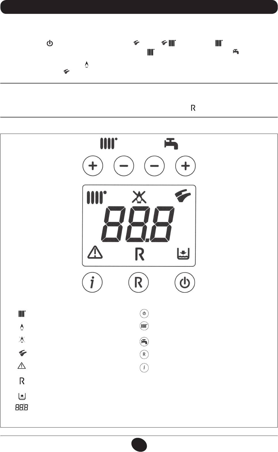
3) press the button ( ) and switch the boiler to Summer ( ), Winter ( ) or heating only ( );
4) press the heating circuit (+/-) and domestic hot water circuit ( ) temperature adjustment buttons ( ) in order to ignite
the main burner.
When the boiler is lit, the symbol ( ) will appear on the display.
In the Summer position ( ) the main burner will only ignite if a DHW tap is opened.
WARNING
During initial ignition, the burner may not ignite (causing the boiler to shut down) until any air in the gas pipes is vented. In
this case, repeat the ignition procedure until gas reaches the burner. Press button ( ), for at least 2 seconds.
0805_2302 / CG_2072
SYMBOL KEY
BUTTON KEY
Operation in the heating mode
On / Off / Summer / Winter / heating only
Flame present (burner on)
(+/-) : CH temperature adjustment
No ame (ignition failure)
(+/-) : DHW temperature adjustment
Operation in the DHW mode
Reset
Generic fault
Information
RESET
No water (Low system pressure)
Numerical signal (Temperature, fault code, etc.)
Figure 1
OPERATING INSTRUCTIONS
71.03982.03 - EN
70
4. ADJUSTING ROOM TEMPERATURE AND DHW TEMPERATURE
The system must be tted with a room thermostat for controlling indoor temperature.
Adjust the room temperature ( ) and the DHW temperature ( ) by pressing the respective +/- (gure 1). The ignition
of the burner is shown on the display with the symbol ( ) as described in section 3.
HEATING
While the boiler is operating in the heating mode, the display (gure 1) shows the ashing symbol ( ) and the heating
delivery temperature (°C).
DOMESTIC HOT WATER
While the boiler is operating in the DHW mode, the display (gure 1) shows the ashing symbol ( ) and the DHW output
temperature (°C).
5. DESCRIPTION OF BUTTON (Summer - Winter - Heating only - Off)
Press this button to set the following operating modes:
• SUMMER
• WINTER
• HEATING ONLY
• OFF
In the SUMMER mode, the display shows ( ). The boiler satises requests for DHW only while central heating is NOT
enabled (ambient frost protection function active).
In the WINTER mode, the display shows ( ). The boiler satises requests for both DHW and central heating (am-
bient frost protection function active).
In the HEATING ONLY mode, the display shows ( ). The boiler satises requests for central heating only (ambient frost
protection function active).
In the OFF mode, the display shows neither of the above two symbols ( ) ( ). In this mode, only the ambient frost
protection function is active while requests for DHW and central heating are not satised.
OPERATING INSTRUCTIONS
71.03982.03 - EN
71
6. FILLING THE SYSTEM
WARNING
Disconnect the boiler from the mains power supply using the two-pole switch.
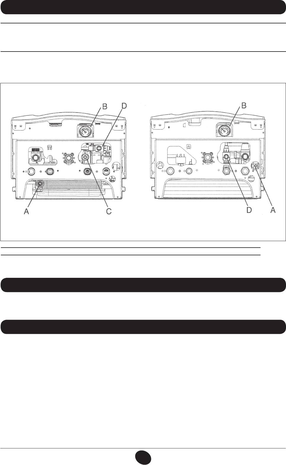
IMPORTANT: Regularly check that the pressure displayed on the pressure gauge is 0.7 - 1.5 bar, with the boiler cold.
In case of overpressure, open the boiler drain tap. In case of insufcient temperature, open the boiler lling tap (gure 3).
Open the tap very slowly in order to vent the air.
24 MI FF - 24 MI 24 FF - 24
CG_2262 / 1007_2901
A - System drain tap
B – Pressure gauge
C - System lling tap
(supplied as an accessory for models 24 FF - 24)
Figure 2
D – Disconnector
The boiler is tted with a hydraulic pressure gauge which prevents the boiler from working if there is no water.
N.B.: In case pressure drops occur frequently, have the boiler checked by an authorised Service Engineer.
7. TURNING OFF THE BOILER
To turn off the boiler, disconnect the electric power supply. In “OFF” mode (section 5) the boiler remains off (the display
indicates OFF) though the electrical circuits remain live and the frost protection device is enabled (section 9).
8. GAS CONVERSION
The boilers can operate both on natural gas and LPG.
All gas conversions must be made by an authorised Service Engineer.
OPERATING INSTRUCTIONS
71.03982.03 - EN
72
9. PROLONGED SHUTDOWN. FROST PROTECTION
Do not drain the whole system as lling up with water again causes unnecessary and harmful scale to build up inside the
boiler and the heating elements. If the boiler is not used during winter and is therefore exposed to the danger of frost, add
some specic anti-freeze to the water in the system (e.g.: propylene glycol coupled with corrosion and scale inhibitors).
The electronic boiler management system includes a “frost protection” function for the heating system which, when delivery
temperature falls below 5°C, operates the burner until a delivery temperature of 30°C is reached.
The frost protection function is enabled if:
* the boiler is electrically powered;
* the gas tap is open;
* the system is at the correct pressure;
* the boiler is not blocked.
10. TROUBLESHOOTING
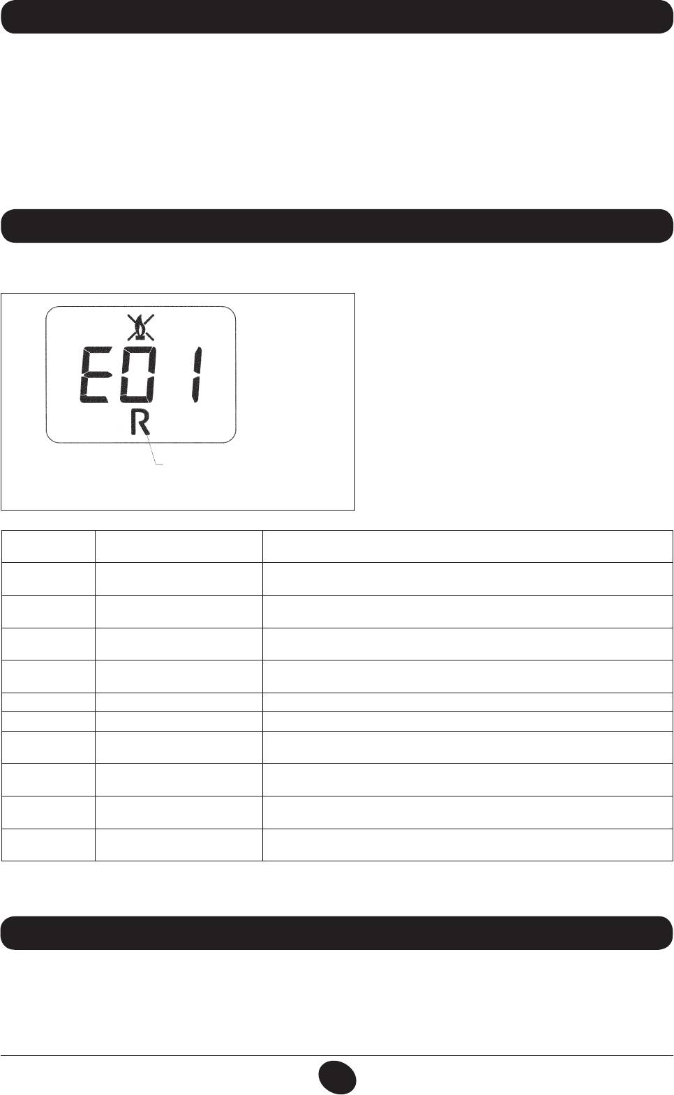
Faults are shown on the display with an error code (e.g.: E 01):
To RESET the boiler, press and hold down “R” for at
least 2 seconds. If this fault persists, call the Authorised
Service Centre.
0607_1205
N.B.: 5 reset attempts can be performed after which
the boiler shuts down. To reset again, switch off the
boiler for a few seconds.
RESETTABLE
faults
Figure 3
CODE
FAULT CORRECTIVE ACTION
DISPLAYED
Press and hold down “R” for at least 2 seconds. If this fault persists, call the
E01 Failed ignition shutdown
Authorised Service Centre.
Press and hold down “R” for at least 2 seconds. If this fault persists, call the
E02 Safety thermostat tripped
Authorised Service Centre.
Flue thermostat/ ue pressure
E03
Call the Authorised Service Centre.
switch tripped
Shutdown after 6 consecutive
Press and hold down “R” for at least 2 seconds. If this fault persists, call the
E04
ame losses
Authorised Service Centre.
E05 Flow sensor failure Call the Authorised Service Centre.
E06 DHW sensor fault Call the Authorised Service Centre.
Hydraulic pressure switch
Check that the pressure in the system is correct; See section 6. If this fault
E10
block
persists, call the Authorised Service Centre.
Probable blocked pump safety
E25/E26
Call the Authorised Service Centre.
trip
Press and hold down “R” for at least 2 seconds. If this fault persists, call the
E35 Parasite ame (ame error)
Authorised Service Centre.
Switching off due to reductions
E96
RESET is automatic. If this fault persists, call the Authorised Service Centre
in power supply
N.B.: in case of a fault, the display backlighting ashes together with the error code.
11. ROUTINE MAINTENANCE INSTRUCTIONS
To keep the boiler efcient and safe, have it checked by the authorised Service Centre at the end of every operating period.
Careful servicing ensures economical operation of the system.
Do not clean the outer casing of the appliance with abrasive, aggressive and/or easily ammable cleaners (e.g.: petrol,
alcohol, and so on). Always switch off the appliance before cleaning it (see section 7 Switching off the boiler).
OPERATING INSTRUCTIONS
71.03982.03 - EN
73
12. GENERAL INFORMATION
The following notes and instructions are addressed to tters to allow them to carry out trouble-free installation. Instructions
for igniting and using the boiler are contained in the ‘Instructions for Users’ section.
• This boiler can be connected to any type of double- or single-pipe convector plate, radiator or thermoconvector. Design
the system sections as usual, though, bearing in mind the available ow-head at the plate, as shown in section 25.
• Do not leave any packaging (plastic bags, polystyrene, etc.) within reach of children, as it is a potential source of danger.
• Initial lighting of the boiler must be carried out by an authorised Service Engineer, as indicated on the attached sheet.
Failure to observe the above will render the guarantee null and void.
ADDITIONAL PUMP WARNING
If an additional pump is used on the heating system, position it on the boiler return circuit. This will allow the correct
operation of the water pressure switch.
SOLAR WARNING
if the instantaneous (mixed) boiler is connected to a system with solar panels, the maximum temperature of the domestic
hot water entering the boiler must not exceed 60°C.
13. INSTRUCTIONS PRIOR TO INSTALLATION
This boiler has been designed to heat water to a temperature lower than boiling point at atmospheric pressure.
It must be connected to a central heating system and to a domestic hot water supply system according to its performance
and power output.
Do the following before connecting the boiler:
a) Make sure that the boiler is adjusted to use the type of gas delivered by the gas supply. To do this, check the markings
on the packaging and the rating plate on the appliance.
b) Make sure that the ue terminal draft is appropriate, that the terminal is not obstructed and that no exhaust gases
from other appliances are expelled through the same ue duct, unless the latter has been specially designed to collect
exhaust gas from more than one appliance, in compliance with current laws and regulations.
c) Make sure that, if the boiler is connected to existing ue ducts, these have been thoroughly cleaned as residual products
of combustion may detach from the walls during operation and obstruct the ow of fumes.
To ensure correct operation and maintain the warranty, observe the following precautions:
1. DHW circuit:
1.1. If the water is harder than 20 °F (1 °F = 10 mg calcium carbonate per litre of water), install a polyphosphate dispenser
or an equivalent treatment system, compliant with current regulations.
1.2. Thoroughly ush the system after installation of the appliance and before use.
1.3. The materials used for the product’s DHW circuit comply with Directive 98/83/CE.
2. Heating circuit
2.1. new system
Before proceeding with installation of the boiler, the system must be cleaned and ushed to eliminate residual
thread-cutting swarf, solder and any solvents, using suitable proprietary products. To avoid damaging metal, plastic
and rubber parts, only use neutral cleaners, i.e. non-acid and non alkaline. Recommended cleaning products are:
SENTINEL X300 or X400 and FERNOX Regenerator for heating circuits. Use these products in strict compliance
with the manufacturers’ instructions.
2.2. existing system:
Before installing the boiler, drain the system and clean it to remove sludge and contaminants, using suitable
proprietary products as described in section 2.1.
To avoid damaging metal, plastic and rubber parts, use only neutral cleaners, i.e. non-acid and non-alkaline such
as SENTINEL X100 and FERNOX Protector for heating circuits. Use these products in strict compliance with the
manufacturers’ instructions.
Remember that the presence of foreign bodies in the heating system can adversely affect boiler operation (e.g.
overheating and excessive noise of the heat exchanger).
Failure to observe the above will render the warranty null and void.
INSTALLATION INSTRUCTIONS
71.03982.03 - EN
74
13. INSTALLAZIONE DELLA CALDAIA 14. INSTALLING THE BOILER
After deciding the exact location of the boiler, make sure there is sufcient room to perform maintenance operations (at
least 450 mm of headroom is required in order to replace the expansion vessel).
Connect the system to the gas and water inlets present on the lower bar of the template. Fit two G3/4 taps (ow and
return) on the central heating circuit; these taps make it possible to carry out important operations on the system without
draining it completely. If you are either installing the boiler on an existing system or replacing one, as well as the above,
t a settling tank under the boiler on the system return line in order to collect any deposits and scale circulating in the
system after ushing. After xing the boiler to the template, connect the ue and air ducts, supplied as accessories, as
described in the following sections.
If the model 24 MI - 24 natural draught boiler is installed, connected it to the ue with a metal pipe resistant to normal
mechanical stress, heat, products of combustion and relative condensate.
IMPORTANT
After lling the boiler, vent the entire internal circuit and the system as follows:
• close the gas on-off valve;
• power the boiler.
• open the vent valve on the pump body;
• press ( ) to set the boiler in the “WINTER” operating mode;
• send a heat demand from the room thermostat;
• open a hot water tap to alternate CH demand with DHW demand;
• after a few ignition attempts the boiler will shut down (error E01 appears on the display);
• to rest, press and hold down “R” for at least 2 seconds;
• repeat the procedure at least another two times;
• close the vent valve.
After venting the boiler circuit, proceed with initial lighting.
EXPANSION VESSEL
The boiler features a standard 6-litre expansion vessel with a pre-charge pressure of 1 bar. The maximum volume of water in
the system is calculated according to hydrostatic pressure at an average water temperature of 80°C (ow: 95°C return: 75°C).
Hydrostatic pressure (m) 5 6 7 8 9 10
Maximum system volume (l) 110 105 95 85 77 70
INSTALLATION INSTRUCTIONS
71.03982.03 - EN
75
24 MI - 24 MI FF 24 - 24 FF
CG_2263 / 1007_1403
Figure 4
G”3/4 HEATING FLOW G”1/2 DOMESTIC HOT WATER OUTLET
G”3/4 HEATING RETURN G”1/2 DOMESTIC COLD WATER INLET
G”3/4 GAS INLET TO BOILER G”3/4 STORAGE BOILER COIL FLOW
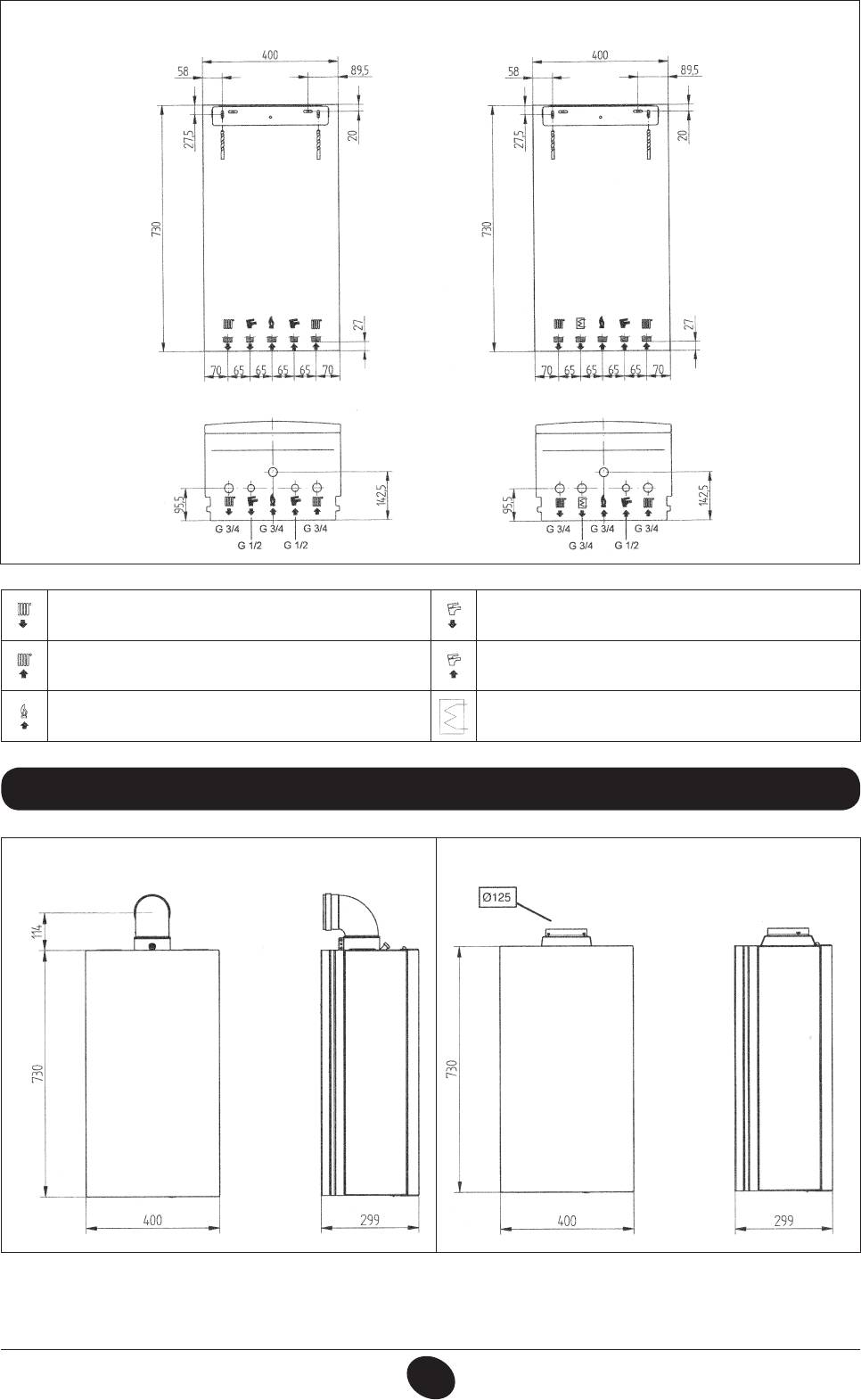
14. DIMENSIONI CALDAIA 15. DIMENSIONS OF BOILER
24 FF - 24 MI FF 24 - 24 MI
CG_2009 / 1006_1803
CG_2009 / 1006_1802
Figure 5
WARNING
Tighten the boiler nipple water connections with care (maximum tightening torque 30 Nm).
INSTALLATION INSTRUCTIONS
71.03982.03 - EN
76
16. INSTALLING THE FLUE AND AIR DUCTS
Model 24 MI FF - 24 FF
The boiler is easy and exible to install thanks to the ex-
tensive range of available accessories, as described below.
The boiler has been designed for connection to a vertical
or horizontal coaxial ue-air duct. A splitting kit is also
available if separate ducts are required.
Only accessories supplied by the manufacturer must
be used for installation!
WARNING: To optimise operating safety, make sure
0503_0905/CG1638
the flue ducts are firmly fixed to the wall with suitable
brackets.
Figure 6
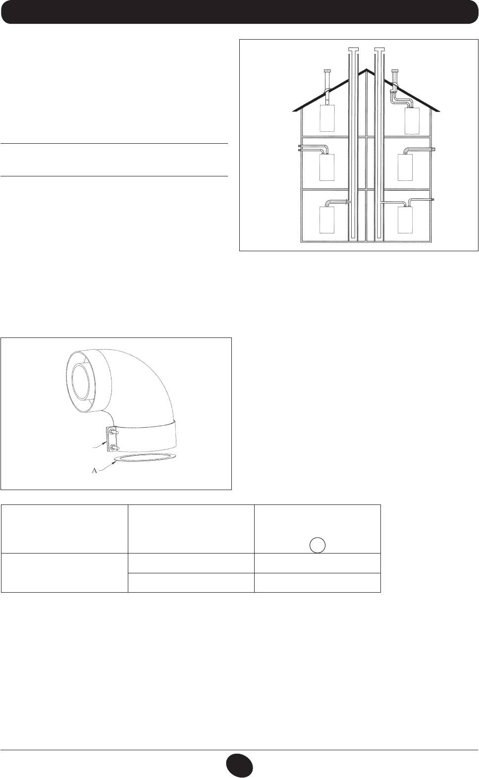
… COAXIAL FLUE-AIR DUCT (CONCENTRIC)
This type of duct is used to discharge exhaust fumes and draw combustion air both outside the building and if a LAS ue
is tted.
The 90° coaxial curve allows the boiler to be connected to a ue-air duct in any direction as it can be rotated by 360°. It
can also be used as a supplementary curve combined with a coaxial duct or a 45° curve.
If fumes are discharged outside the building, the ue-air duct
must protrude at least 18 mm from the wall to allow an alu-
minium weathering surround to be tted and sealed to avoid
water inltrations.
Make sure there is a minimum upward slope towards the
0805_2901 / CG_2073
outside of 1 cm per metre of duct.
•
A 90° curve reduces total duct length by 1 metre.
•
A 45° curve reduces total duct length by 0.5 metres.
Connector
The first 90° curve is not considered when calculating the
maximum available length.
Figure 7
Use of DIAPHRAGM
Boiler model Length (m)
on INLET LINE
A
0 ÷ 1 Yes
24 MI FF
24 FF
1 ÷ 4 No
INSTALLATION INSTRUCTIONS
71.03982.03 - EN
77
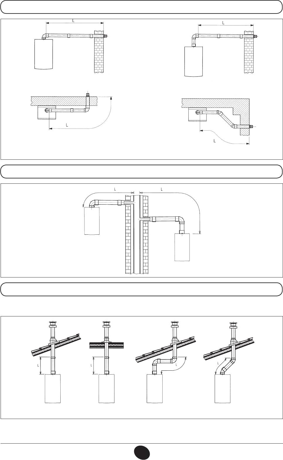
16.1 HORIZONTAL FLUE INSTALLATION EXAMPLES
L max = 4 m (Ø 60/100 mm)
10 m (Ø 80/125 mm)
L max = 4 m (Ø 60/100 mm)
10 m (Ø 80/125 mm)
0512_2001
L max = 3 m (Ø 60/100 mm)
L max = 3 m (Ø 60/100 mm)
9 m (Ø 80/125 mm)
9 m (Ø 80/125 mm)
16.2 LAS FLUE DUCT INSTALLATION EXAMPLES C42 TYPE
L max = 4 m (Ø 60/100 mm)
10 m (Ø 80/125 mm)
16.3 VERTICAL FLUE INSTALLATION EXAMPLES
This type of installation can be carried out on either a at or a pitched roof by tting a ue terminal and a special weathering
surround with sleeve (both available on request).
0503_0908/CG1641 0503_0907/CG1640
L max = 9 m (Ø 80/125 mm)
L max = 7 m (Ø 80/125 mm)
L max = 8 m (Ø 80/125 mm)
For detailed installation instructions, consult the technical data provided with the accessories.
INSTALLATION INSTRUCTIONS
71.03982.03 - EN
78
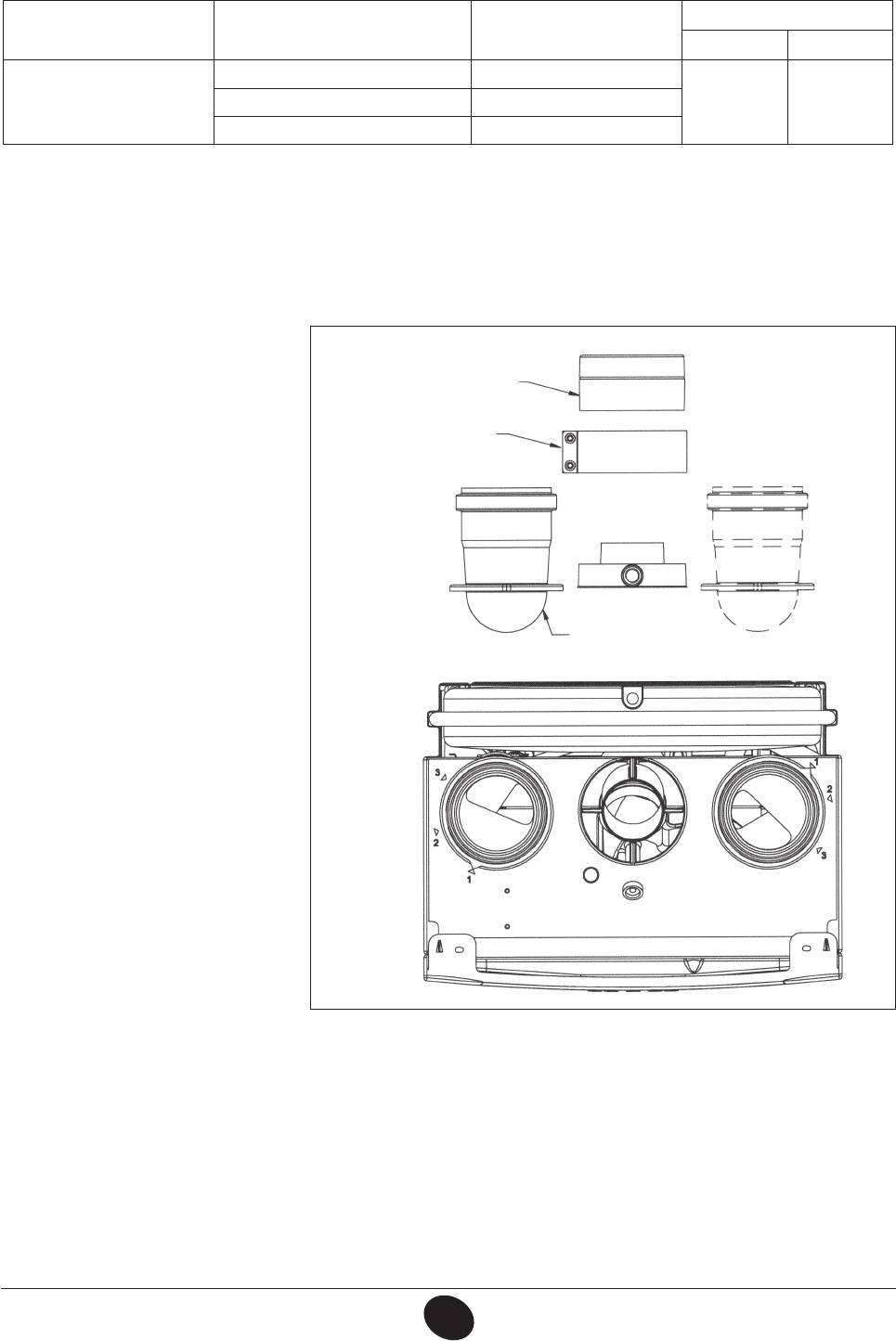
… SEPARATE FLUE AND AIR DUCTS
This type of installation makes it possible to discharge exhaust fumes both outside the building and into single ue ducts.
Comburent air can be drawn in at a different location from that of the ue terminal. The splitting kit comprises a ue duct
adaptor (100/80) and an air duct adaptor. For the air duct adaptor, t the screws and seals previously removed from the cap.
Position
CO
%
2
Boiler model (L1+L2)
of air regulator
G20 G31
0 ÷ 4 1
24 MI FF
7,2 84 ÷ 18 2
24 FF
18 ÷ 30 3
The first 90° curve is not considered when calculating the maximum available length.
The 90° curve allows the boiler to be connected to a ue-air duct in any direction as it can be rotated by 360°. It can also
be used as a supplementary curve combined with a duct or a 45° curve.
• A 90° curve reduces total duct length by 0.5 metres.
• A 45° curve reduces total duct length by 0.25 metres.
Adjusting the air regulator for sepa-
rate flues
Flue duct adaptor
This regulator must be adjusted to
optimise combustion efficiency and
parameters.
Connector
After turning the air intake connecter,
0809_0201 / CG_2045
which can be mounted both to the right
and the left of the exhaust ue duct,
suitably adjust the excess air according
to the total length of the combustion
exhaust and inlet ue ducts.
Turn this regulator anticlockwise to de-
crease the excess of comburent air and
vice-versa to increase it.
To ne tune, use a combustion product
Air intake restrictor
analyser to measure the amount of CO
2
in the fumes at maximum heat capacity,
and, if a lower value is measured, gra-
dually adjust the air regulator until the
amount of CO
indicated in the following
2
table is measured.
To mount this device correctly, consult
the relative instructions
.
Figure 8
INSTALLATION INSTRUCTIONS
71.03982.03 - EN
79

16.4 DIMENSIONS OF SEPARATE OUTLETS
CG_2124 / 0905_2305
16.5 HORIZONTAL SEPARATE FLUE INSTALLATION EXAMPLES - C82
IMPORTANT -
Make sure there is a minimum downward slope towards the outside of 1 cm per metre of duct length.
In the event of installation of the condensate collection kit, the angle of the drain duct must be directed towards the boiler.
1010_0102/CG1643
CG_1643_FR / 1010_0101
L max = 10 m
(L1 + L2) max = 30 m
N.B.: For the C52 type, do not t the ue and air duct terminals on opposite walls of the building.
The inlet ue must have a maximum length of 10 metres for C52 fumes outlets.
If the discharge duct is longer than 6 metres, install the condensate collection kit, supplied as an accessory, near the boiler
IMPORTANT:
if tting a single ue duct, make sure it is adequately insulated (e.g.: with glass wool) wherever the duct
passes through building walls. For detailed installation instructions, consult the technical data provided with the accessories.
INSTALLATION INSTRUCTIONS
71.03982.03 - EN
80


