De Dietrich MS 24 MI – страница 5
Инструкция к Настенному Котлу De Dietrich MS 24 MI
17. ELECTRICAL CONNECTIONS
This machine is only electrically safe if it is correctly connected to an efcient earth system in compliance with current
safety regulations.
Connect the boiler to a 230V single-phase earthed power supply using the supplied three-pin cable, observing correct
LIVE-NEUTRAL polarity.
Use a double-pole switch with a contact separation of at least 3 mm. When replacing the power supply cable, t a
2
harmonised HAR H05 VV-F’ 3x0.75mm
cable with a maximum diameter of 8 mm.
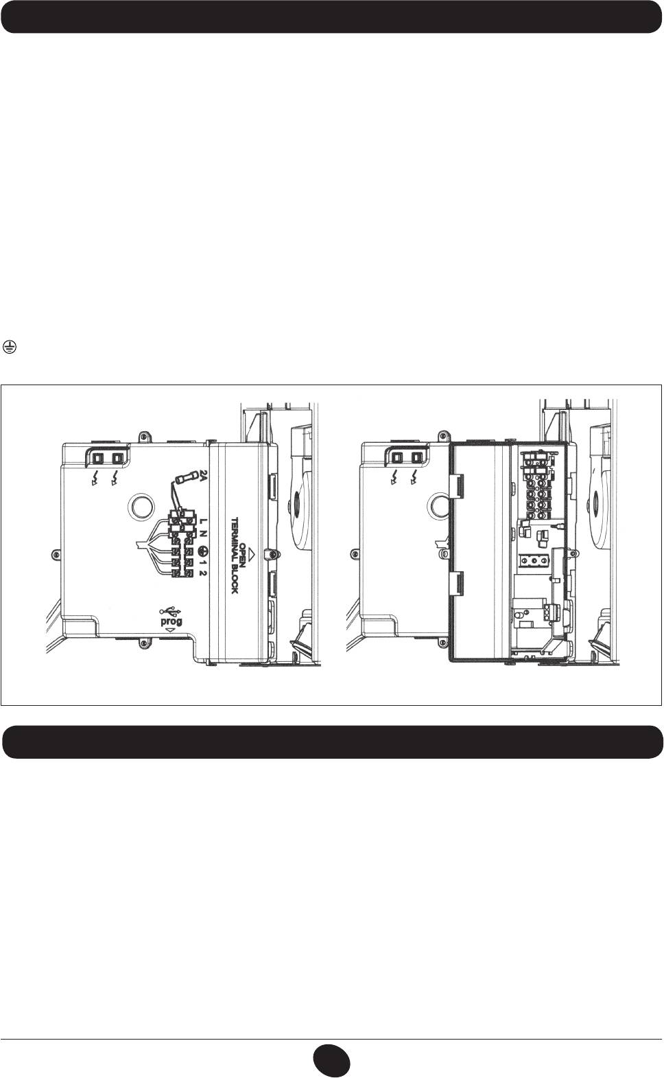
…Access to the power supply terminal block
• disconnect the boiler from the mains power supply using the two-pole switch;
• remove the two screws xing the control panel to the boiler;
• rotate the control panel;
• remove the cover and access the wiring area (gure 9).
The 2A fast-blowing fuse is incorporated in the power supply terminal block (to check and/or replace the fuse, pull out
the black fuse carrier).
IMPORTANT: respect polarity L (LIVE) -N (NEUTRAL).
(L) = Live (brown)
(N) = Neutral (blue)
= Earth (yellow-green)
(1) (2) = Contact for room thermostat
CG_2008 / 1009_0301
Figure 9
18. CONNECTING THE ROOM THERMOSTAT
• Access the power supply terminal block (gure 9) as described in the previous section;
• remove the jumper on terminals (1) and (2);
• thread the two-wire cable through the grommet and connect it to these two terminals.
INSTALLATION INSTRUCTIONS
71.03982.03 - EN
81
19. GAS CONVERSION
The authorised Technical Assistance Service can convert this boiler to natural gas (G. 20) or liquid gas (G.31).
Carry out the following operations:
A) replace the nozzles of the main burner and the gas diaphragm (if tted);
B) new max. and min. calibration of the pressure regulator.
A) Replace the burner nozzles
• carefully pull the main burner off its seat;
• replace the main burner nozzles making sure to fully tighten them to prevent gas leaks. Nozzle diameters are specied
in table 2.
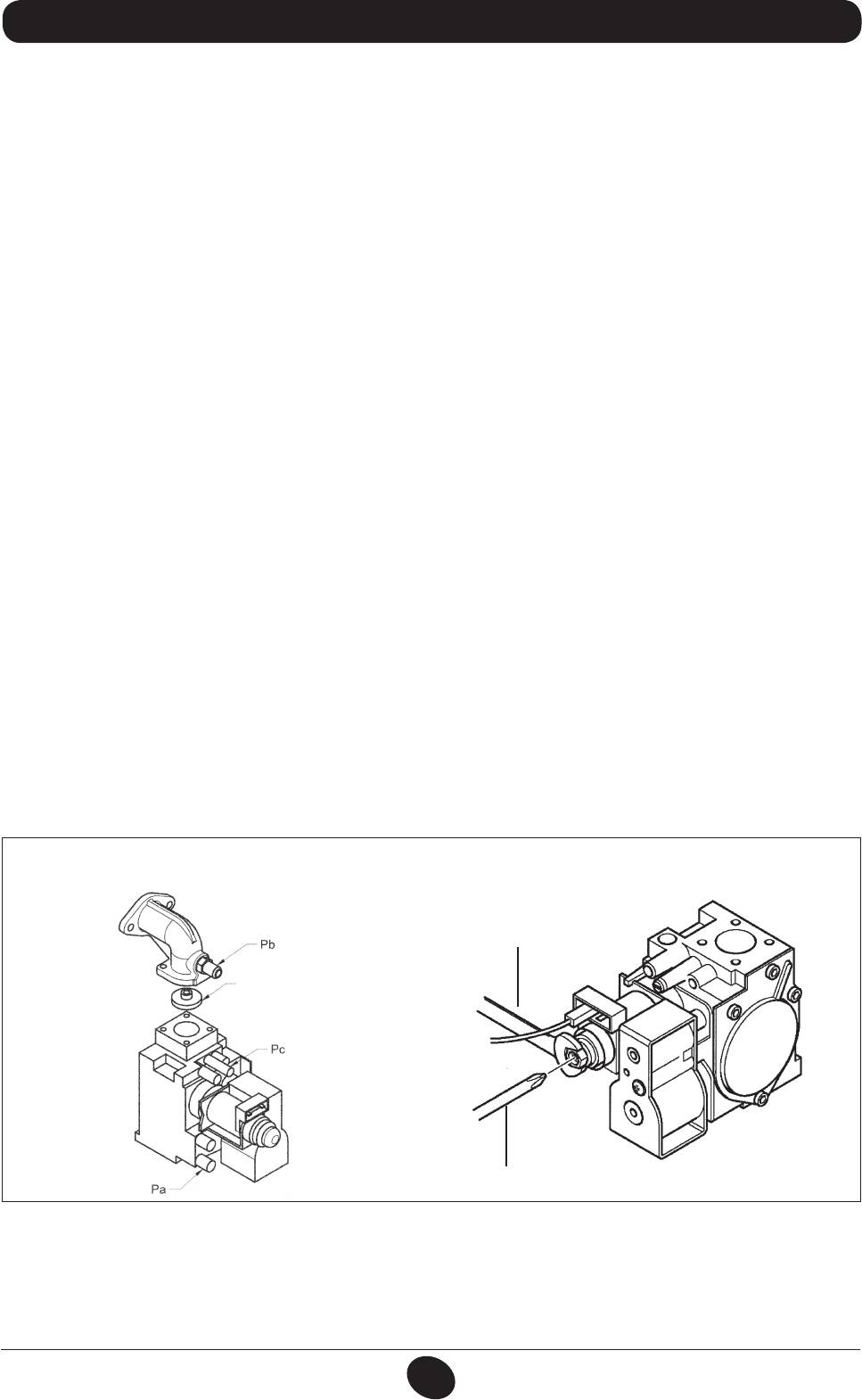
B) Calibrate the pressure regulator
• connect the positive pressure test point of a differential pressure gauge (possibly water-operated) to the gas valve
pressure test point (Pb) (Figure 10). Only for models with sealed chambers, connect the negative pressure test point of
the manometer to a “T” tting in order to join the boiler adjustment outlet, the gas valve adjusting outlet (Pc) and the
pressure gauge. (The same measurement can be made by connecting the pressure gauge to the pressure test point
(Pb) after removing the front panel of the sealed chamber);
Measuring burner pressure using methods other than those described could lead to incorrect results as the low pressure
created by the fan in the sealed chamber would not be taken into account.
B1) Adjustment to nominal heat output:
• open the gas tap and switch the boiler to the Winter mode;
• open a hot water tap that can provide a ow rate of at least 10 litres a minute or make sure there is maximum heat
demand;
• remove the modulator cover;
• adjust the tube brass screw (a) until the pressure values shown in table 1 are obtained;
make sure that the dynamic inlet pressure of the boiler, measured at the gas valve pressure test point (Pa) (Figure 10) is
correct (37 mbar for propane or 20 mbar for natural gas).
B2) Adjustment to reduced heat output:
• disconnect the modulator power cable and unscrew the screw (b) until a pressure value corresponding to reduced heat
output is achieved (see tab. 1);
• reconnect the cable;
• mount the modulator cover and seal.
B3) Final checks
• attach the additional plate supplied with the transformer, specifying the type of gas and the calibration performed.
gas valve
mod. SIGMA 845
a
0605_1502
CG_2273 / 1008_2602
gas diaphragm
Figure 10
b
Figure 11
ATTENTION
If the natural gas inlet pressure is too low (less than 17 mbar) remove the gas diaphragm installed over the gas valve (g.
10) and set parameter F02=00 on the electronic board (§21).
INSTALLATION INSTRUCTIONS
71.03982.03 - EN
82
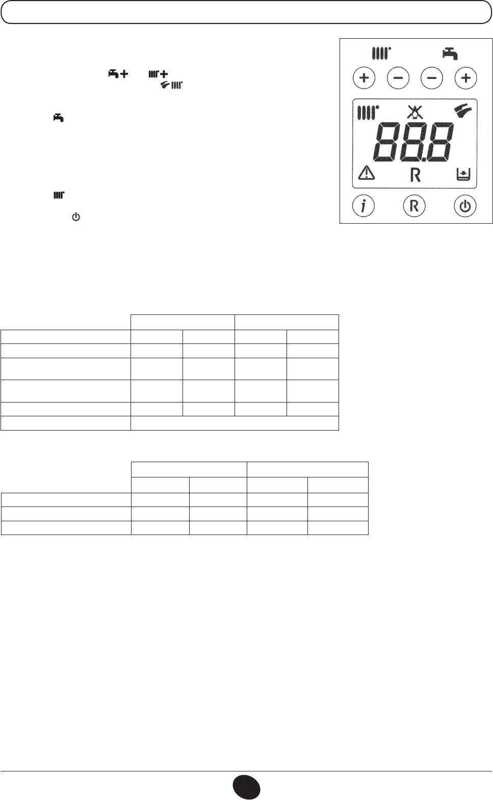
19.1 GAS VALVE CALIBRATION FUNCTION
To simplify calibration of the gas valve, the calibration function may be set directly
on the boiler control panel as follows:
a) hold down the buttons and together for at least 6 seconds;
b) after about 6 seconds, the symbols ash;
c) the display shows, at intervals of one second, “100” and the flow temperature.
0805_2302 / 1002_1201
In this phase, the boiler works at the maximum heating output (100%).
d) press +/- to immediately set the power of the boiler (100% or 0%);
e) adjust the “Pmax/Pmin” screw (gure 10) to set the burner pressure value as
described in table 1.
To adjust pressure at maximum power, turn the “Pmax” screw (g. 10) clockwise
to increase or anti-clockwise to decrease pressure at the burner.
To adjust pressure at minimum power, turn the “Pmin” screw (g. 10) clockwise
to increase or anti-clockwise to decrease pressure at the burner.
f) press +/- to gradually set the desired power level (interval = 1%).
Press the button to leave the function.
Note:
The function is automatically deactivated after a period of 15 minutes, at the end of which the electronic board returns to
its operating status prior to the activation of the function or prior to reaching the set maximum temperature.
Table of burner nozzles
24 MI FF - 24 FF 24 - 24 MI
gas type G20 G31 G20 G31
diameter of nozzles (mm) 1,28 0,77 1,18 0,77
Burner pressure (mbar*)
2,0 5,7 2,4 5,6
REDUCED HEAT OUTPUT
Burner pressure (mbar*)
11,6 32,6 13,8 31,0
RATED HEAT OUTPUT
Diameter of gas diaphragm (mm) 4,8 — 5,5 —
N° nozzles 13
Table 1
Consumption 15°C-1013 mbar
24 MI FF - 24 FF 24 - 24 MI
G20 G31 G20 G31
3
3
Rated power
2,80 m
/h 2,00 kg/h
2,80 m
/h 2,04 kg/h
3
3
Reduced power
1,12 m
/h 0,82 kg/h
1,12 m
/h 0,82 kg/h
3
3
p.c.i.
34,02 MJ/m
46,34 MJ/kg
34,02 MJ/m
46,34 MJ/kg
Table 2
* 1 mbar = 10,197 mmH
O
2
INSTALLATION INSTRUCTIONS
71.03982.03 - EN
83
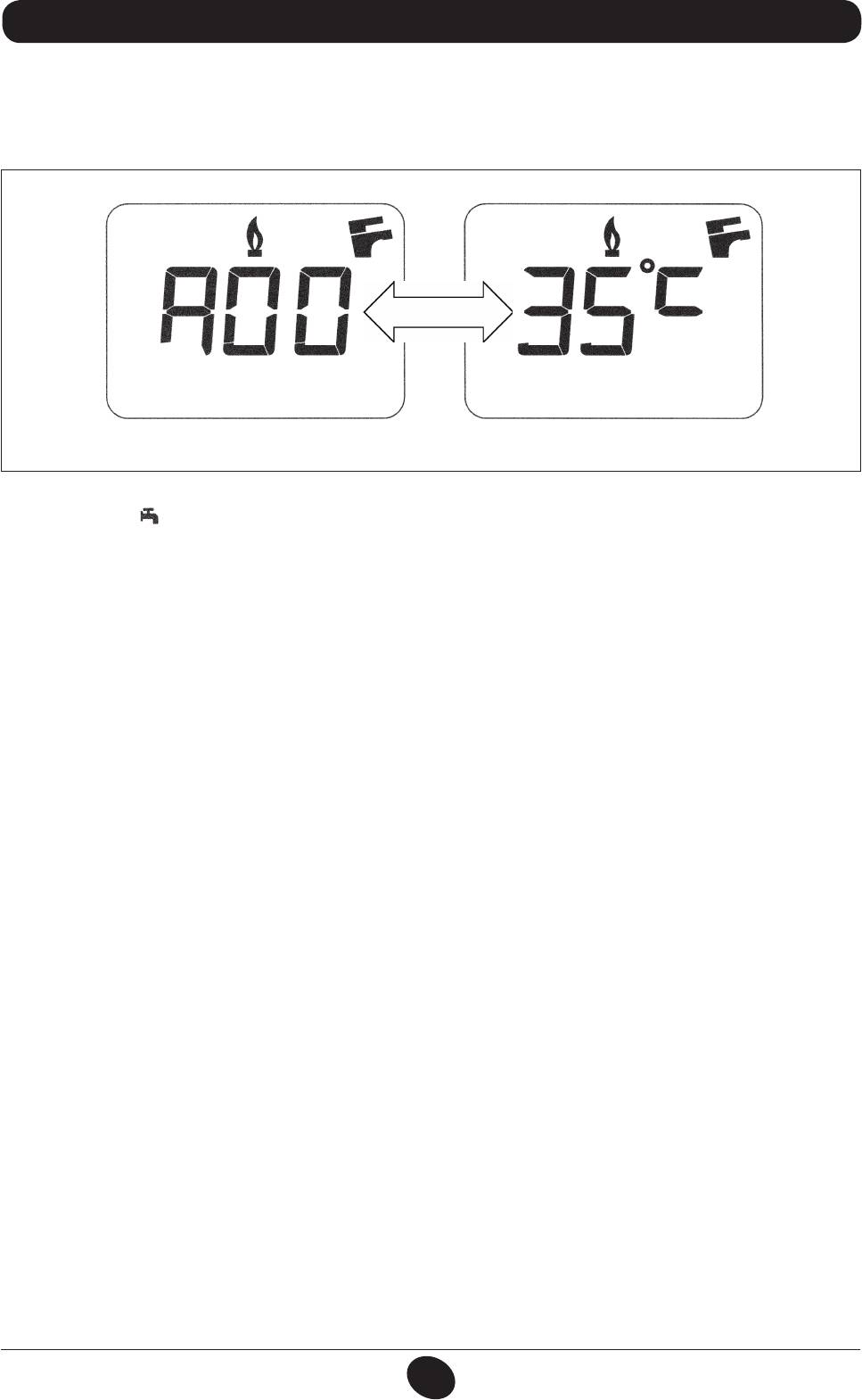
20. VISUALISATION OF PARAMETERS ON THE DISPLAY (“INFO” FUNCTION)
Press “i” for at least 5 seconds to visualise certain boiler information on the display on the front panel of the boiler.
N.B: when the “INFO” function is enabled, the message “A00”, alternating with the boiler delivery temperature,
is shown on the display (figure 12):
0605_2204 / CG_1808
Figure 12
Press buttons (+/-) to display the following information:
•
A00: current DHW temperature (°C);
A01: current external temperature (°C) (with external sensor connected);
A02: modulation current value (100% = 310 mA METHANE - 100% = 310 mA LPG);
A03: power range (%) (MAX R);
A04: heating setpoint temperature (°C) - - If the external sensor is connected, the value of the “kt” curve is displayed
(section 26);
A05: current heating delivery temperature (°C);
A06: DHW temperature setpoint (°C);
A07: — — ;
A08: value (l/minx10) of the DHW ow rate;
A09: last error that occurred in the boiler.
This function remains active for 3 minutes. It is possible to interrupt the “INFO” function in advance by pressing button
•
(i) for at least 5 seconds, or turning off the power to the boiler.
INSTALLATION INSTRUCTIONS
71.03982.03 - EN
84
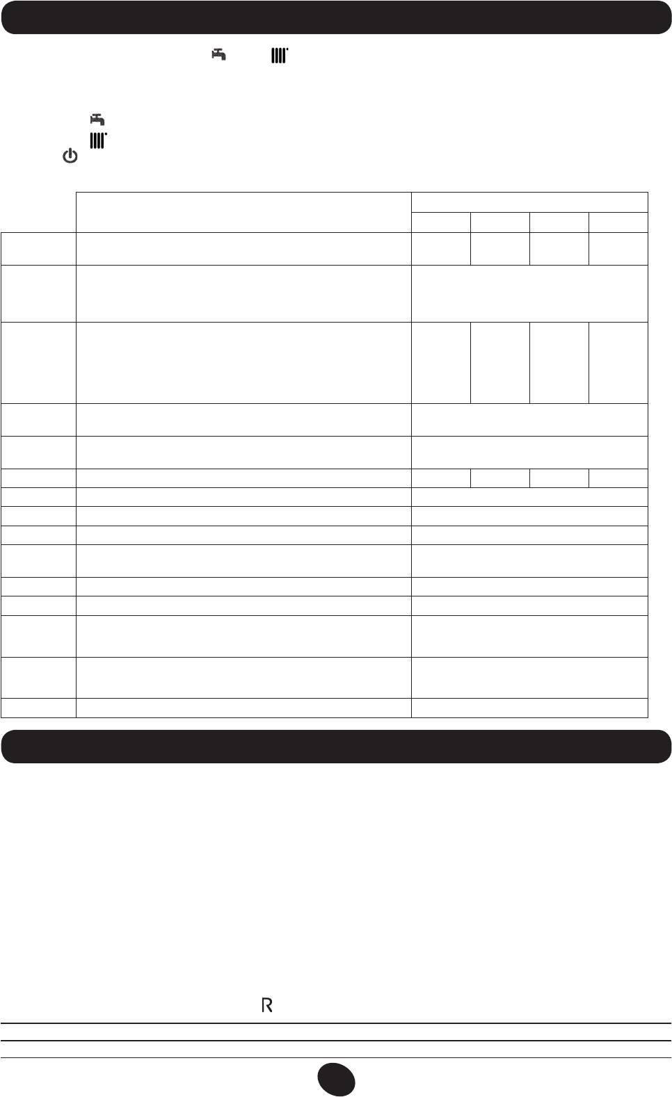
21. PARAMETER SETTINGS
To set the boiler parameters, press (– ) and (– ) together and hold down for at least 6 seconds. When the function is
activate, the “F01” appears on the display alternating with the value of the parameter shown.
Edit parameters
• Press (+/– ) to scroll through the parameters;
• Press (+/– ) to edit each parameter;
• Press ( ), to save the changes. “MEM” appears on the display;
• Press (i), to exit without saving. “ESC” appears on the display.
Factory settings
Description of parameters
24 MI FF 24 FF 24 MI 24
Type of boiler
F01
10 10 20 20
10 = sealed chamber 20 = atmospheric chamber
Gas used
00 = METHANE
F02
02
01 = LPG
02 = METHANE (WITH DIAPHRAGM)
Hydraulic system
00 = instantaneous appliance
03 = appliance with external storage boiler
F03
13 04 13 04
04 = appliance for heating only
13 = preheating (24h)
14 = preheating (1h)
Setting programmable relays 1 and 2 (See SERVICE instructions)
F04/ F05
00
00 = no associated function
Maximum CH setpoint (°C)
F06
00
00 = 85°C - 01 = 45°C (function unavailable)
F07
DHW inlet priority conguration
00 01 00 01
F08
CH max. output (0-100%)
100
F09
DHW max. output (0-100%)
100
F10
Min. heating output (0-100%)
00
Delay prior to new ignition in CH mode
F11
03
(00-10 minutes) - 00=10 seconds
F12
Diagnostics (See SERVICE Instructions)
--
F13-F14-F15
Factory settings
00
Anti-legionella function (with F03=03)
F16
00 = disabled
00
55...67 = enabled (setpoint °C)
CH pressure sensor selection
F17
00 = hydraulic pressure sensor
00
01 = hydraulic differential pressure sensor
F18
Manufacture information
00
22. ADJUSTMENT AND SAFETY DEVICES
The boiler has been designed in full compliance with European reference standards and in particular is tted with the
following:
• Air pressure switch (model 24 MI FF - 24 FF)
This device only allows the burner to ignite if the exhaust ue duct is in perfect working order.
In the event of one or more of the following faults:
• ue terminal obstructed
• venturi tubes obstructed
• fan blocked
• venturi tube connection - pressure switch tripped
the boiler remains on standby and error code E03 is displayed (see table in section 10).
• Fumes thermostat (model 24 MI - 24)
This device has a sensor positioned on the left section of the fumes hood and shuts off the gas ow to the main burner
if the ue is obstructed and/or if there is no draught.
In these conditions the boiler shuts down and displays error code E03 (section 10).
After eliminating the problem, press button ( ), for at least 2 seconds to re-ignite immediately.
It is forbidden to disable this safety device
INSTALLATION INSTRUCTIONS
71.03982.03 - EN
85
• Safety thermostat
Thanks to a sensor placed on the CH ow line, this thermostat interrupts the ow of gas to the burner if the water in
the primary circuit overheats. In these conditions, the boiler is blocked and only after the fault has been eliminated can
it be ignited again by pressing ( ), for at least 2 seconds.
It is forbidden to disenable this safety device
• Flame ionization detector
The ame sensing electrode, located on the right-hand side of the burner, guarantees safety of operation in case of gas
failure or incomplete ignition of the burner.
In these conditions, the boiler is blocked after 3 ignition attempts.
Press ( ), for at least 2 seconds to re-establish normal operating conditions.
• Hydraulic pressure switch
This device allows the main burner to be ignited only if system pressure is higher than 0.5 bars.
• Pump overrun for heating circuit
The electronically-controlled pump post-circulation function lasts 180 seconds and is enabled, in the heating mode, if
the ambient thermostat causes the burner to go out.
• Pump overrun for DHW circuit
The electronically-controlled pump post-circulation function lasts 30 seconds and is enabled, in the DHW mode, if the
probe causes the burner to go out.
• Frost protection device (CH and DHW systems)
The electronic boiler management system includes a “frost protection” function for the heating system which, when
delivery temperature falls below 5°C, operates the burner until a delivery temperature of 30°C is reached.
This function is enabled when the boiler is switched on, the gas supply is open and the system is correctly pressurised.
• Water not circulating in primary circuit (pump probably blocked)
If there is insufcient or no water circulating in the primary circuit, the boiler blocks and the error code E25 is shown on
the display (section 10).
• Anti-block pump function
If no heat demand is received for 24 consecutive hours, in the heating mode, the pump will automatically start and
operate for 10 seconds. This function is operative when the boiler is powered.
• Three-way valve anti-blockage function
If no heat demand is received for a period of 24 hours, the three-way valve performs a complete switching cycle. This
function is operative when the boiler is powered.
• Hydraulic safety valve (heating circuit)
This device is set to 3 bar and is used for the heating circuit
.
Connect the safety valve to a drain trap. Do not use it to drain the heating circuit.
N.B.: domestic hot water is guaranteed even if the NTC sensor develops a fault. In this case, temperature is controlled
by the delivery sensor.
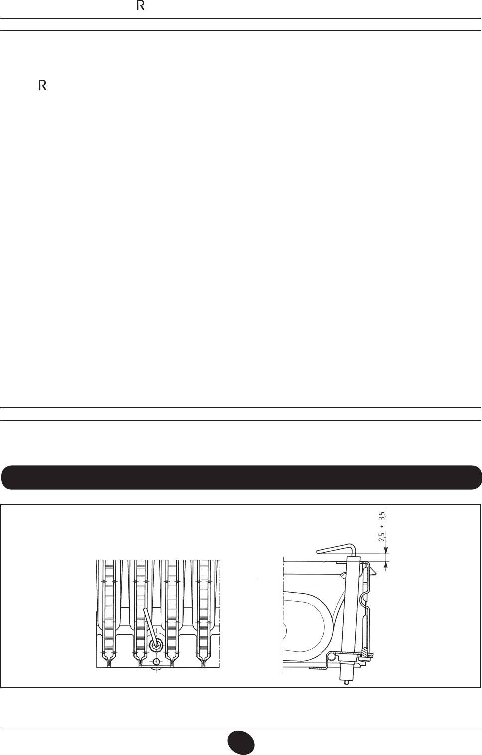
23. POSITIONING THE IGNITION AND FLAME-SENSING ELECTRODE
9912070100
Figure 13
INSTALLATION INSTRUCTIONS
71.03982.03 - EN
86
24. CHECKING COMBUSTION PARAMETERS
To measure combustion efciency and the toxicity of the products of combustion, the boiler is tted with two dedicated
test points.
One connection point is connected to the exhaust duct and is used to measure combustion efciency and the toxicity of
the products of combustion.
The other is connected to the air intake circuit and is used to check for the presence of any products of combustion
circu¬lating in installations with co-axial ues.
The following parameters can be measured using the test point connected to the exhaust duct:
• temperature of the products of combustion;
• concentration of oxygen (O
) or, alternatively, carbon dioxide (CO
);
2
2
• concentration of carbon monoxide (CO).
The temperature of the comburent air must be measured on the test point located on the air intake ue by inserting the
measurement sensor by about 3 cm.
N.B.: to regulate the rated power, see chapter 19 (B1)
For natural draught boiler models, a hole must be made in the exhaust ue at a distance from the boiler equal to twice
the internal diameter of the ue.
The following parameters can be measured through this hole:
• temperature of the products of combustion;
• concentration of oxygen (O
) or, alternatively, carbon dioxide (CO
);
2
2
• concentration of carbon monoxide (CO).
The temperature of the combustion air must be measured close to the point where the air enters the boiler. The hole,
which must be made by the person in charge of the system during commissioning, must be sealed so as to ensure that
the exhaust duct is airtight during normal operation
.
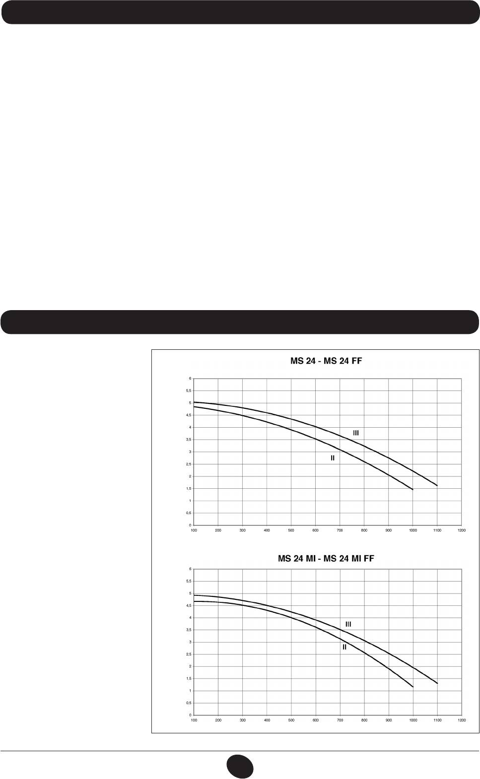
25. PUMP CAPACITY/ HEAD
A high static head pump (GRUN-
DFOS UPSO 15-50), suitable for
installation on any type of single- or
1009_24011009_2402
double-pipe heating system, is used.
The automatic air valve incorporated
in the pump allows quick venting of
the heating system.
O
2
HEAD mH
FLOW l/h
O
2
HEAD mH
Graph 1
FLOW l/h
INSTALLATION INSTRUCTIONS
71.03982.03 - EN
87

26. CONNECTING THE EXTERNAL SENSOR
The wiring harness leaving the control board includes two RED wires tted with faston covers. Connect the external sensor
to these two wires.
With the external sensor connected, the “kt” curve (Graph 2) can be changed by pressing +/- .
N.B.: In case of installation in an average living unit (good perimeter insulation and radiator systems), set the “kt” climate
curve to “25”.
“kt” curves
TM
1012_0501
TM = Flow temperature range
Te
Te = External temperature
Graph 2
27. CONNECTING AN EXTERNAL STORAGE BOILER
Model 24 - 24FF
The DHW priority sensor NTC is supplied as an accessory.
CONNECTING THE STORAGE BOILER SENSOR
The boiler can be connected to an external storage boiler. Hydraulically connect the storage boiler as shown in g. 14.
Connect the DHW priority sensor NTC to terminals 5-6 on terminal block M2. The sensitive element of the NTC sensor must
be inserted in the special well located on the storage boiler. Adjust DHW temperature (35 °C...60 °C) by pressing +/– .
KEY:
UB STORAGE BOILER
UR HEATER
V3V EXTERNAL THREE-WAY VALVE
M2 CONNECTING TERMINAL
BLOCK
SB DHW PRIORITY STORAGE
CG_2085 / 1101_1701
BOILER SENSOR
MR HEATING FLOW
MB STORAGE BOILER FLOW
RR HEATING / STORAGE BOILER
RETURN
Figure 14
IMPORTANT : Make sure that parameter F03 = 03 (section 21).
INSTALLATION INSTRUCTIONS
71.03982.03 - EN
88
28. ANNUAL SERVICING
To optimise boiler efciency, carry out the following annual controls:
• check the appearance and air-tightness of the gaskets of the gas and combustion circuits;
• check the state and correct position of the ignition and ame-sensing electrodes;
• check the state of the burner and make sure it is rmly xed;
• check for any impurities inside the combustion chamber.
Use a vacuum cleaner to do this;
• check the gas valve is correctly calibrated;
• check the pressure of the heating system;
• check the pressure of the expansion vessel;
• check the fan works correctly;
• make sure the ue and air ducts are unobstructed.
WARNINGS
Before commencing any maintenance operations, make sure the boiler is disconnected from the power supply.
Afterwards, move the knobs and/or operating parameters of the boiler to their original positions.
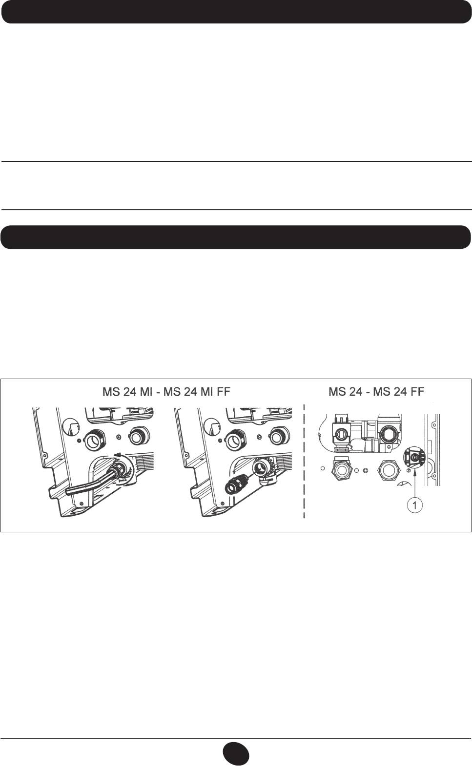
29. DRAINING THE BOILER CIRCUIT
Drain the boiler by opening the drain tap.
In boilers MS 24 MI and MS 24 MI FF the drain tap is located at the bottom while for boilers MS 24 and MS 24 FF it is
next to the pump (1 – g. 15).
To drain the boiler using the drain tap located at the bottom, proceed as follows (g. 15):
- close the boiler on/off valves;
- open the drain tap using an 8 mm hex wrench;
- drain the boiler;
- close the drain tap using the 8 mm hex wrench.
CG_2284 / 1009_2405
Figure 15
INSTALLATION INSTRUCTIONS
71.03982.03 - EN
89

30. CLEANING THE FILTERS
The DHW and CH lters are housed in special extractable cartridges. The CH cartridge is located on the CH return line
(gure 16F) while the DHW cartridge is on the cold water input (gure 16E). To clean the lters, proceed as described below:
• switch off the boiler;
• shut the DHW inlet tap
• drain the water in the CH circuit by opening tap A in gure 16.
• remove the clip (1-E/F) from the lter as illustrated in the gure and take out the cartridge (2-E/F) containing the lter,
taking care not to apply excessive force;
• to extract the heating lter cartridge, rst remove the 3-way valve motor (1-2G - gure 16);
• eliminate any impurities and deposits from the lter;
• reposition the lter in the cartridge and put it back into its housing, securing it with the clip.
• to change the DHW NTC sensor, see gure 16D.
WARNING
when replacing and/or cleaning the O-rings on the hydraulic assembly, only use Molykote 111 as a lubricant, not oil or grease.
31. REMOVING SCALE FROM THE DHW CIRCUIT
The DHW circuit can be cleaned without removing the water-water heat exchanger if the assembly is tted with the special
tap (available on request) located on the DHW outlet. To clean, proceed as follows:
• Close the DHW inlet tap;
• Drain the DHW system by opening a hot water tap;
• Close the DHW outlet tap;
• Remove the clip 1E in gure 16;
• Remove the lter (2E gure 16);
• to change the DHW NTC sensor, see gure 16D.
If the special tap is not supplied, dismount the water-water heat exchanger, as described in the next section, and clean it
separately. Remove the scale from the seat and relative NTC sensor tted on the DHW circuit (gure 16D).
To clean the exchanger and/or DHW circuit, use Cillit FFW-AL or Benckiser HF-AL.
INSTALLATION INSTRUCTIONS
71.03982.03 - EN
90
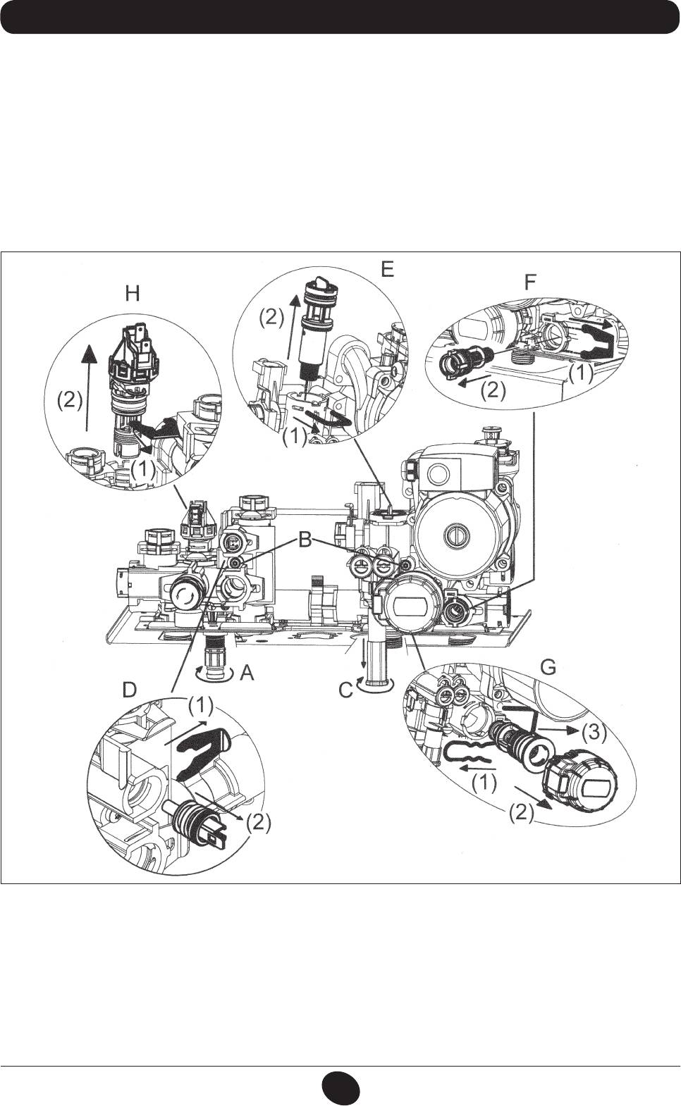
32. DISMOUNTING THE WATER-WATER HEAT EXCHANGER
The stainless steel plate-type water-water heat exchanger can be disassembled with a hex wrench by operating as de-
scribed below:
• drain the system, just the boiler if possible, through the drain tap;
• drain the DHW system;
• unscrew the pipe connecting the expansion vessel to the hydraulic assembly;
• remove the heating pressure switch (16H) without disconnecting the cable harness;
• remove the two screws (g. 16B) at the front securing the water-water heat exchanger and pull it out using the space
created after removing the heating pressure switch;
• clean the heat exchanger and put it back in place;
• screw on the pipe connecting the expansion vessel to the hydraulic assembly;
• put the hydraulic pressure switch back in place.
CG_2078 / 1009_2201
Figure 16
WARNING
Pay great attention when dismantling the individual parts of the hydraulic assembly.
Do not use sharp tools, do not apply excessive force when removing the xing clip.
INSTALLATION INSTRUCTIONS
71.03982.03 - EN
91
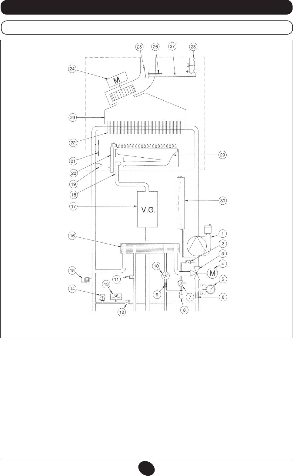
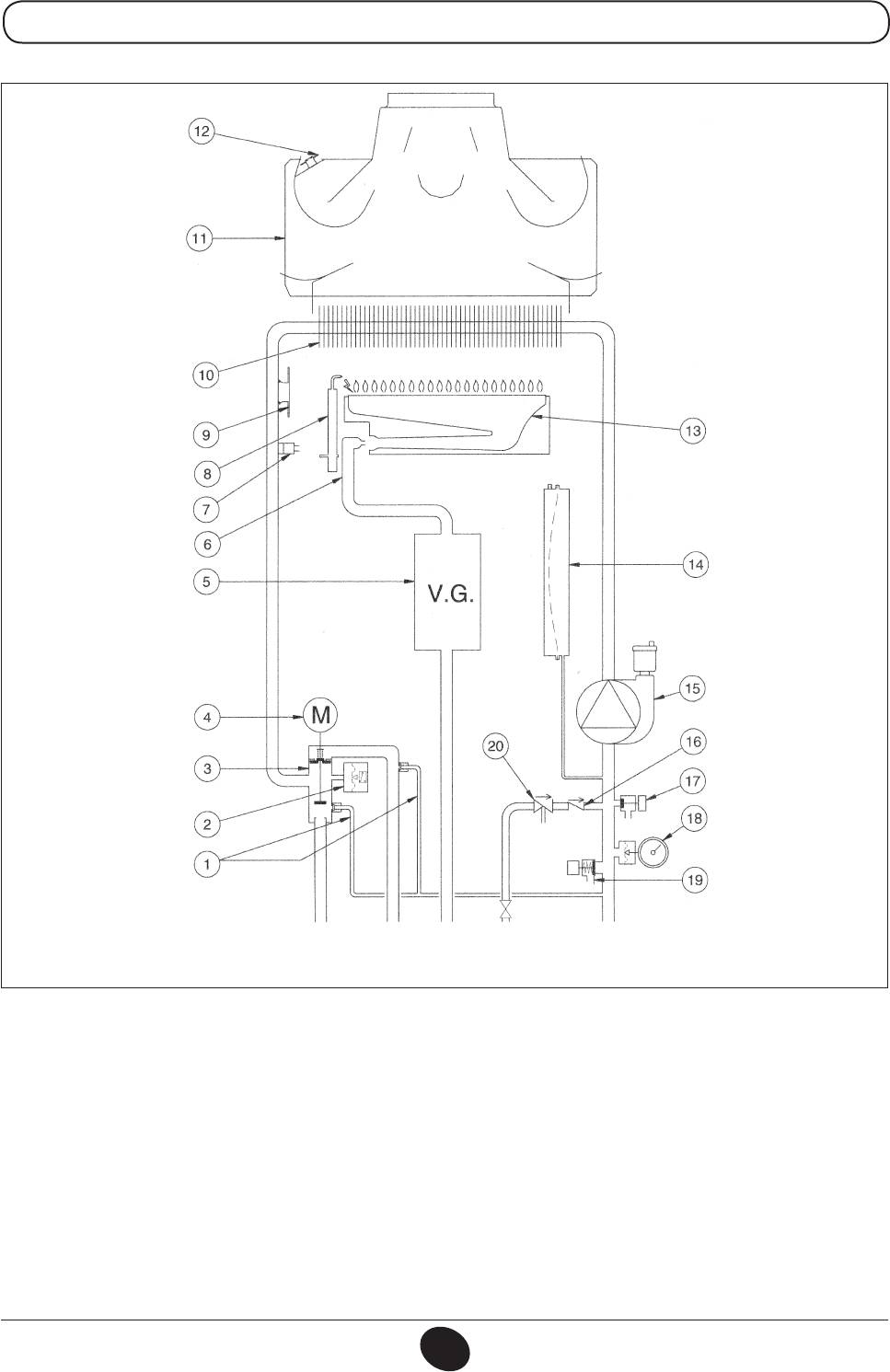
33. FUNCTIONAL CIRCUIT DIAGRAM
24 MI FF
CG_2269 / 1006_1805
Heating ow DHW
Gas DHW
Heating return
outlet
inlet
Figure 17
Key:
1 Pump and air separator
16 Water-water plate heat exchanger
2 No-return valve
17 Gas valve with gas diaphragm
3 Three-way valve
18 Gas train with nozzles
4 Three-way valve motor
19 Central heating NTC sensor
5 Pressure gauge
20 Ignition/ame detection electrode
6 Heating circuit extractable lter
21 Safety thermostat
7 Disconnector
22 Water-fumes exchanger
8 Boiler lling tap
23 Fumes conveyor
9 Cold water extractable lter
24 Fan
10 DHW priority sensor
25 Venturi tube
11 NTC domestic hot water sensor
26 Positive pressure point
12 Check valve on automatic by-pass
27 Negative pressure point
13 Water pressure switch
28 Air pressure switch
14 Boiler drain tap
29 Burner
15 Safety valve
30 Expansion vessel
INSTALLATION INSTRUCTIONS
71.03982.03 - EN
92
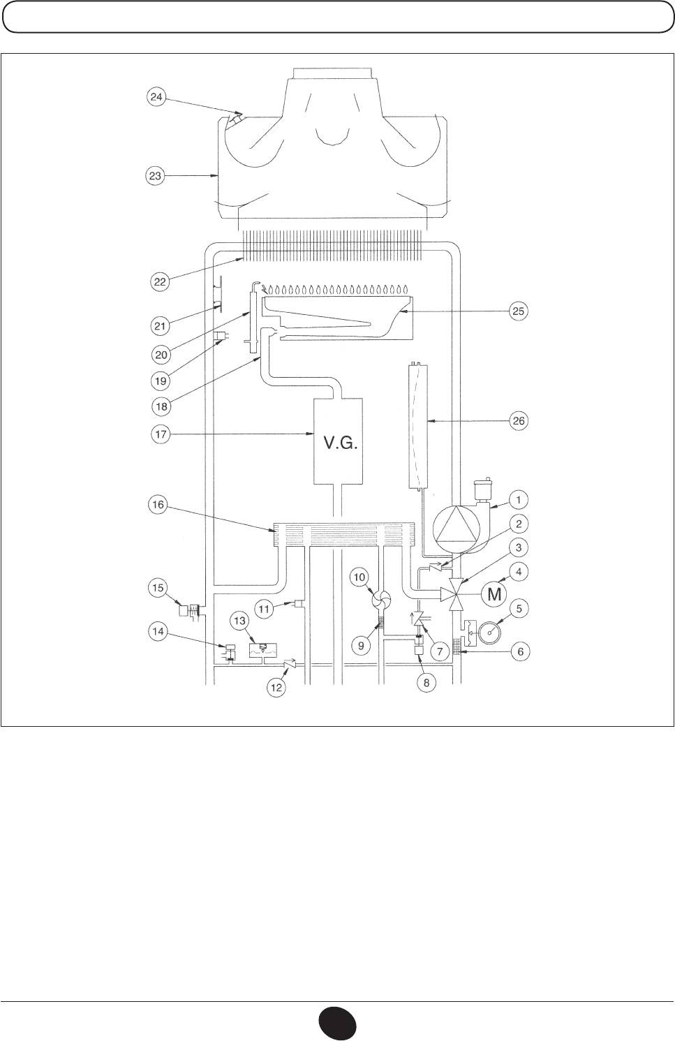
24 MI
CG_2270 / 1006_1806
Heating ow DHW
Gas DHW
Heating return
outlet
inlet
Figure 18
Key:
1 Pump and air separator
14 Boiler drain tap
2 Check valve
15 Safety valve
3 Three-way valve
16 Water-water plate heat exchanger
4 Three-way valve motor
17 Gas valve with gas diaphragm
5 Pressure gauge
18 Gas train with nozzles
6 Heating circuit extractable lter
19 Central heating NTC sensor
7 Disconnector
20 Ignition/ame detection electrode
8 Boiler lling tap
21 Safety thermostat
9 Cold water extractable lter
22 Water-fumes exchanger
10 DHW priority sensor
23 Fumes conveyor
11 NTC domestic hot water sensor
24 Fumes thermostat
12 Check valve on automatic by-pass
25 Burner
13 Water pressure switch
26 Expansion vessel
INSTALLATION INSTRUCTIONS
71.03982.03 - EN
93
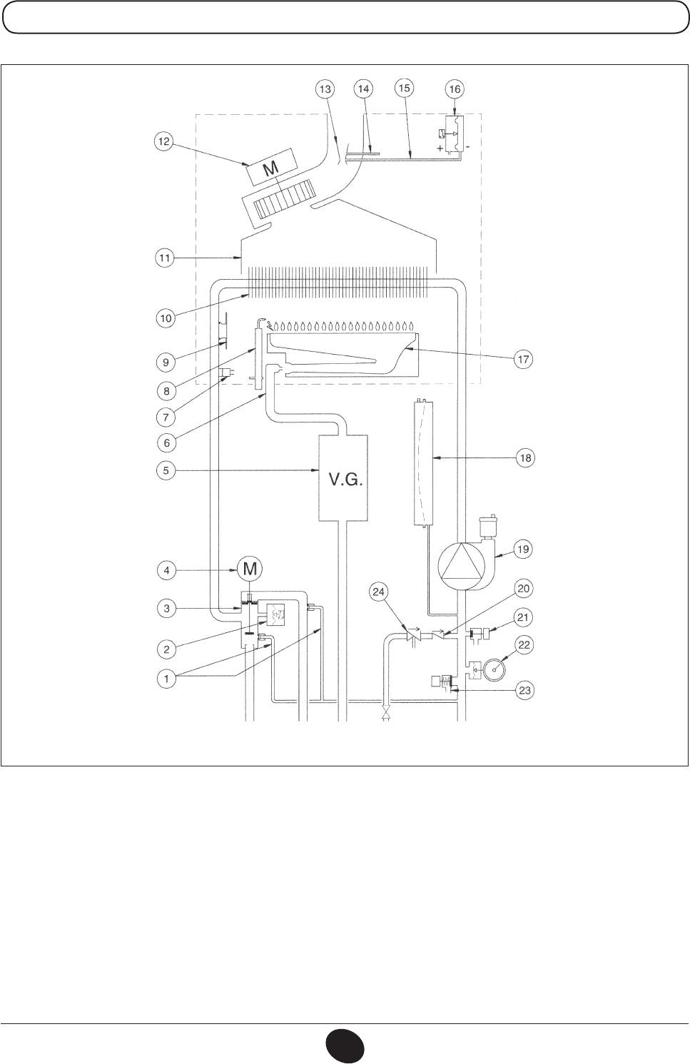
24 FF
CG_2267 / 1006_2102
Heating ow Gas DHW
Storage
Heating return
boiler
inlet
Figure 19
ow
Key:
1 Automatic by-pass with check valve
13 Venturi tube
2 Hydraulic pressure switch
14 Positive pressure tap
3 Three-way valve
15 Negative pressure tap
4 Three-way valve motor
16 Air pressure switch
5 Gas valve with gas diaphragm
17 Burner
6 Gas train with nozzles
18 Expansion vessel
7 NTC heating sensor
19 Pump and air separator
8 Ignition/ame detection electrode
20 Non-return valve
9 Safety thermostat
21 Boiler drain tap
10 Water-fumes exchanger
22 Pressure gauge
11 Fumes conveyor
23 Safety valve
12 Fan
24 Disconnector
INSTALLATION INSTRUCTIONS
71.03982.03 - EN
94
24
CG_2268 / 1006_2103
Heating ow Gas DHW
Storage
Heating return
boiler
inlet
ow
Figure 20
Key:
1 Automatic by-pass with check valve
11 Fumes conveyor
2 Hydraulic pressure switch
12 Fumes thermostat
3 Three-way valve
13 Burner
4 Three-way valve motor
14 Expansion vessel
5 Gas valve with gas diaphragm
15 Pump and air separator
6 Gas train with nozzles
16 Non-return valve
7 NTC heating sensor
17 Boiler drain tap
8 Ignition/ame detection electrode
18 Pressure gauge
9 Safety thermostat
19 Safety valve
10 Water-fumes exchanger
20 Disconnector
INSTALLATION INSTRUCTIONS
71.03982.03 - EN
95
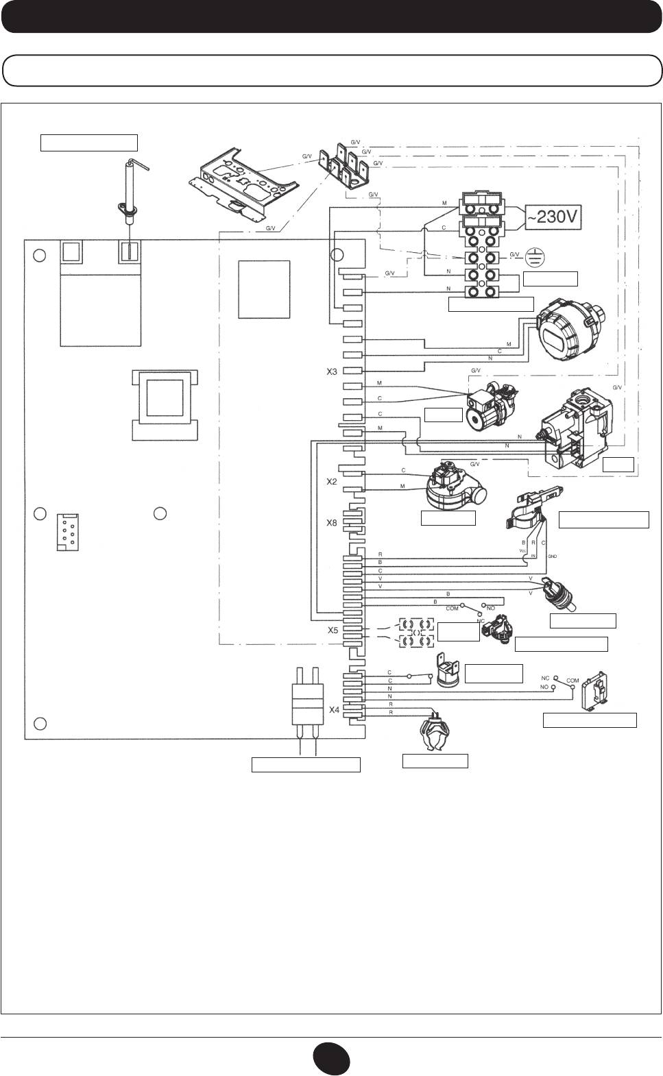
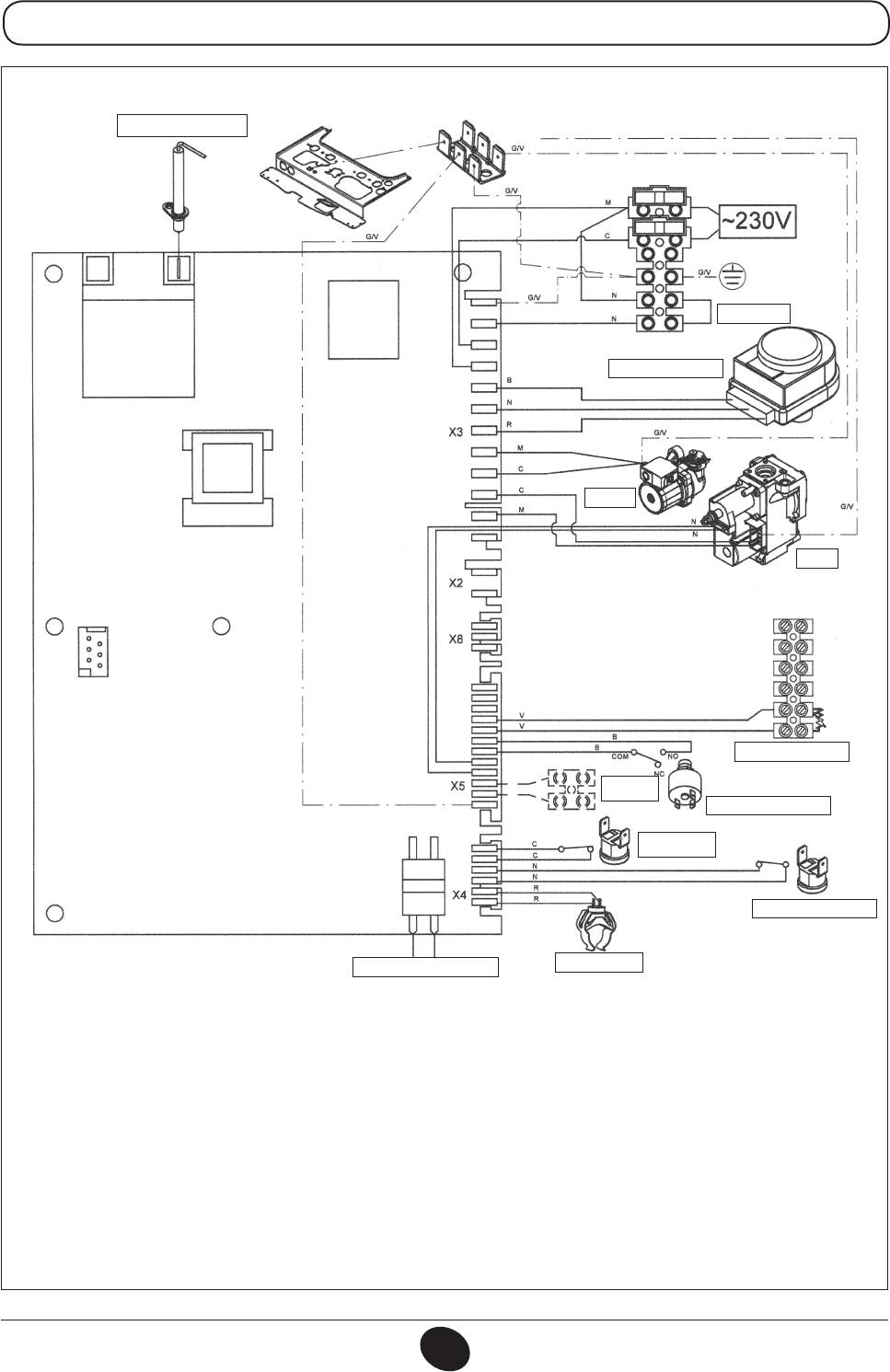
34. WIRING DIAGRAM
24 MI FF
DETECTION/IGNITION
ELECTRODE
CG_2075 / 1001_1806
THERMOSTAT
THREE-WAY VALVE
PUMP
GAS
VALVE
FAN
DOMESTIC WATER
PRIORITY SENSOR
DHW NTC SENSOR.
EXTERNAL
SENSOR
HYDRAULIC PRESSURE
SWITCH
SAFETY
THERMOSTAT
AIR PRESSURE SWITCH
CH NTC SENSOR
PROGRAMMING
Cable colours
C = Light blue
M = Brown
N = Black
R = Red
G/V = Yellow/Green
B = White
V = Green
INSTALLATION INSTRUCTIONS
71.03982.03 - EN
96
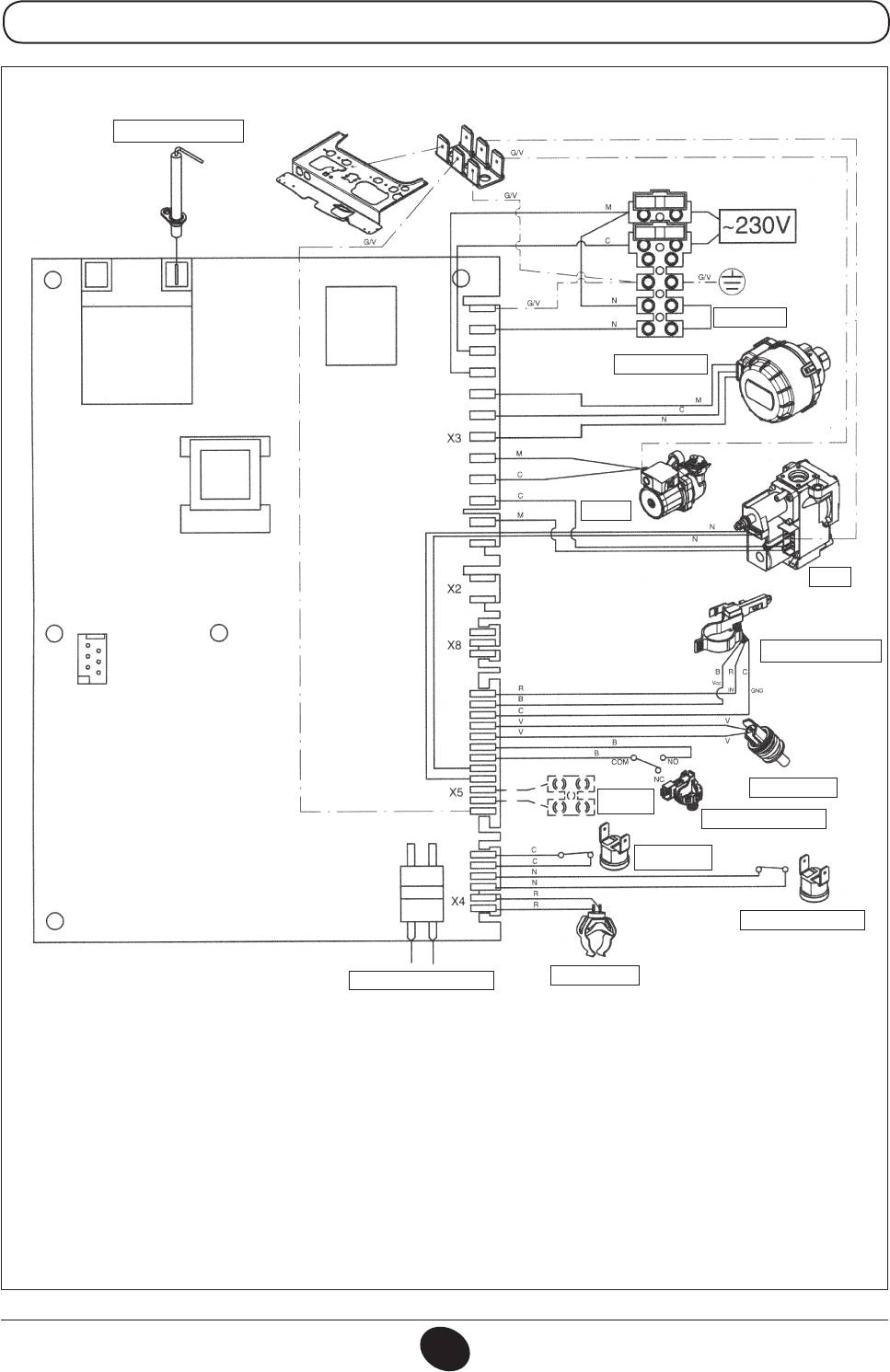
24 MI
DETECTION/IGNITION
ELECTRODE
CG_2076 / 1001_1807
THERMOSTAT
THREE-WAY VALVE
PUMP
GAS
VALVE
DOMESTIC WATER
PRIORITY SENSOR
DHW NTC SENSOR.
EXTERNAL
SENSOR
HYDRAULIC PRESSURE
SWITCH
SAFETY
THERMOSTAT
FUMES THERMOSTAT
CH NTC SENSOR.
PROGRAMMING
Cable colours
C = Light blue
M = Brown
N = Black
R = Red
G/V = Yellow/Green
B = White
V = Green
INSTALLATION INSTRUCTIONS
71.03982.03 - EN
97
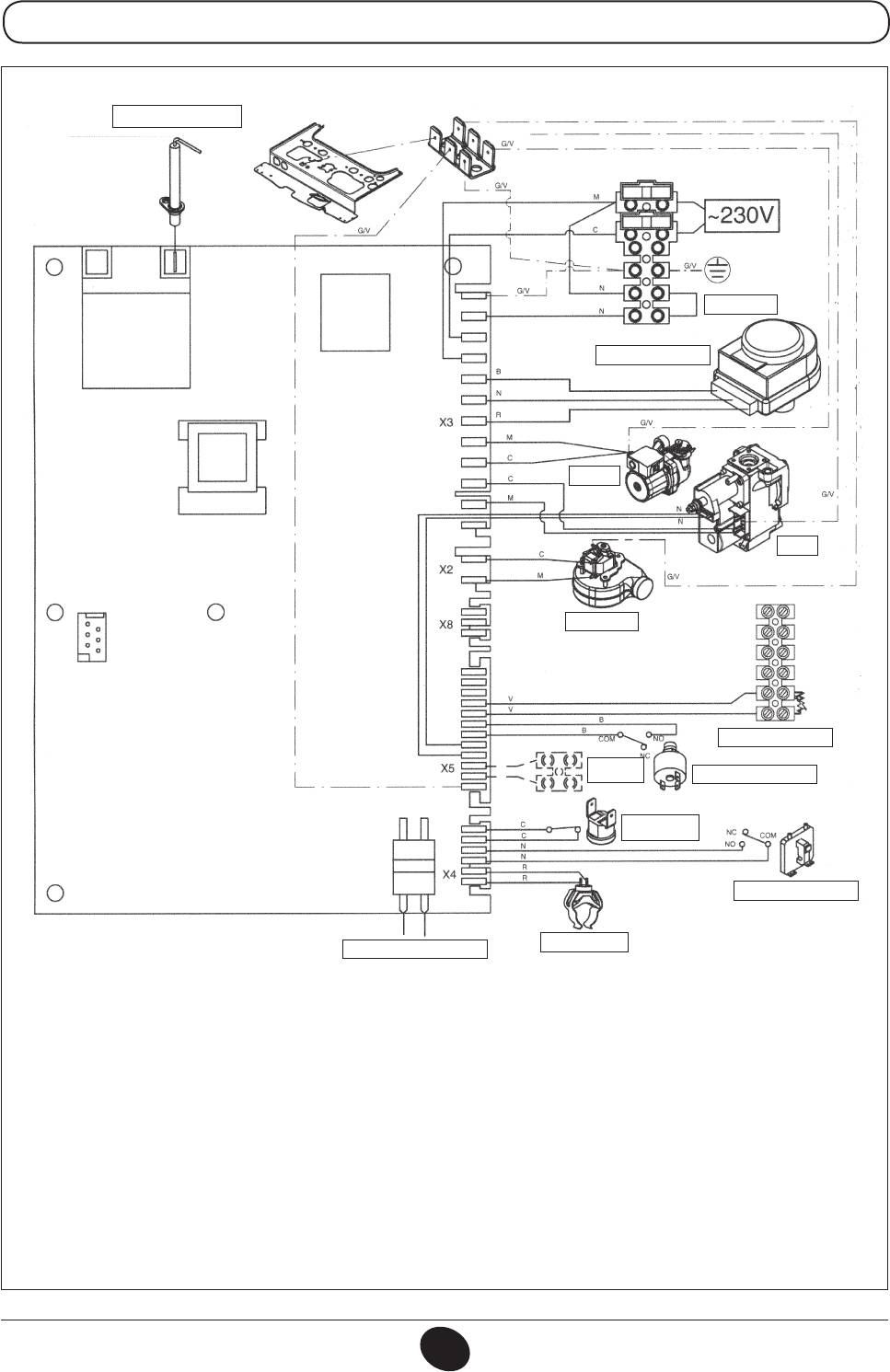
24 FF
DETECTION/IGNITION
ELECTRODE
CG_2271 / 1006_1603
THERMOSTAT
THREE-WAY VALVE
PUMP
GAS
VALVE
FAN
TERMINAL BLOCK M2
EXTERNAL
HYDRAULIC PRESSURE
SENSOR
SWITCH
SAFETY
THERMOSTAT
AIR PRESSURE SWITCH
CH NTC SENSOR.
PROGRAMMING
Cable colours
C = Light blue
M = Brown
N = Black
R = Red
G/V = Yellow/Green
B = White
V = Green
INSTALLATION INSTRUCTIONS
71.03982.03 - EN
98
24
DETECTION/IGNITION
ELECTRODE
CG_2272 / 1010_2101
THERMOSTAT
THREE-WAY VALVE
PUMP
GAS
VALVE
TERMINAL BLOCK M2
EXTERNAL
SENSOR
HYDRAULIC PRESSURE
SWITCH
SAFETY
THERMOSTAT
FUMES THERMOSTAT
CH NTC SENSOR.
PROGRAMMING
Cable colours
C = Light blue
M = Brown
N = Black
R = Red
G/V = Yellow/Green
B = White
V = Green
INSTALLATION INSTRUCTIONS
71.03982.03 - EN
99

35. TECHNICAL SPECIFICATIONS
Model MS 24 MI FF 24 FF 24 MI 24
Category II2H3P
II2H3P
II2H3P II2H3P
Rated heat input
kW 25,8 25,8 26,3 26,3
Reduced heat input
kW 10,6 10,6 10,6 10,6
Rated heat output
kW 24 24 24 24
kcal/h 20.600 20.600 20.600 20.600
Reduced heat output
kW 9,3 9,3 9,3 9,3
kcal/h 8.000 8.000 8.000 8.000
Useful efciency according to directive 92/42/EEC
— ★★★ ★★★ ★★ ★★
Max. water pressure in CH system
bar 3 3 3 3
Expansion vessel capacity
l 6 6 6 6
Expansion vessel pressure
bar 1 1 1 1
DHW max. water pressure
bar 8 — 8 —
DHW min. dynamic water pressure
bar 0,15 — 0,15 —
Minimum DHW ow
l/min 2,0 — 2,0 —
DHW output at ∆T=25 °C
l/min 13,7 — 13,7 —
DHW output at ∆T=35 °C
l/min 9,8 — 9,8 —
Specic output (*)
l/min 12 — 12 —
Temperature range in heating system
°C 30/85 30/85 30/85 30/85
Temperature range in DHW system
°C 35/60 35/60*** 35/60 35/60***
Type
— C12-C32-C42-C52-C82-B22
B
B
11BS
11BS
Coaxial ue duct diameter
mm 60 60 - -
Coaxial air duct diameter
mm 100 100 - -
2-pipe ue duct diameter
mm 80 80 - -
2-pipe air duct diameter
mm 80 80 - -
Flue duct diameter
mm - - 125 125
Max. ue mass ow rate
kg/s 0,014 0,014 0,020 0,020
Min. ue mass ow rate
kg/s 0,014 0,014 0,018 0,018
Max. exhaust temperature
°C 146 146 110 110
Min. exhaust temperature
°C 116 116 85 85
NOx Class
— 3 3 3 3
Type of gas
— G20 G20 G20 G20
— G31 G31 G31 G31
Natural gas supply pressure
mbar 20 20 20 20
Propane gas supply pressure
mbar 37 37 37 37
Power supply voltage
V 230 230 230 230
Power supply frequency
Hz 50 50 50 50
Rated power supply
W 130 130 80 80
Net weight
kg 33 32 29 28
Dimensions Height mm 730 730 730 730
Width mm 400 400 400 400
Depth mm 299 299 299 299
Protection against humidity and water (**) IP X5D IP X5D IP X5D IP X5D
(*) according to EN 625
(**) according to EN 60529
(***) with external storage boiler
As DE DIETRICH constantly strives to improve its products, it reserves the right to modify the information contained in this document at
any time and without prior notice. This document is issued purely for the sake of information and should not be considered as a contract
with third parties.
INSTALLATION INSTRUCTIONS
71.03982.03 - EN
100


